Preparation and Tribological Behaviors of Lubrication-Enhanced PEEK Composites


1
School of Mechanical Engineering and Automation, Northeastern University, Shenyang 110819, China
2
Department of Chemistry, College of Science, Northeastern University, Shenyang 110819, China
*
Authors to whom correspondence should be addressed.
Appl. Sci. 2020, 10(21), 7536; https://doi.org/10.3390/app10217536
Submission received: 17 September 2020
/
Revised: 21 October 2020
/
Accepted: 21 October 2020
/
Published: 26 October 2020
(This article belongs to the Section Mechanical Engineering)
Abstract
:Poly-ether-ether ketone (PEEK) is a great potential thermoplastic in industry and medical treatment and health. In this work, PEEK/graphene oxide (GO) and PEEK/MoS2 composites were prepared by a novel hot isostatic pressing method. The addition of GO alters the tribological behaviors mechanism; fatigue wear mechanism is predominant to PEEK/GO composites. However, the combination of abrasive and adhesive wear mechanisms is observed for PEEK/MoS2 composites and PEEK. The reason for this is that the hardness and tensile strength of composites are increased with the appropriate addition of GO. The response time to stable friction state of PEEK/GO and PEEK/MoS2 composites is reduced in comparison with PEEK, which is conducive to shorten running-in time, reduce the energy consumption, and improve the tribological performances of composites. The addition of GO and MoS2 can effectively decrease the friction coefficient and wear rate, and the optimal content of GO and MoS2 was 0.7 wt.% and 15 wt.%, respectively. The results indicate that PEEK/GO and PEEK/MoS2 are impressive composites that possess super tribological properties.
1. Introduction
Poly-ether-ether ketone (PEEK), first synthesized by Bonner in 1962, is an excellent aromatic semicrystalline thermoplastic engineering plastic. PEEK possesses great mechanical properties [1,2], excellent chemical corrosion resistance, thermal stability and suitable tribological characteristics [3], high radiation resistance [4], good machinability, and electrical properties [5]. PEEK is widely used in the fields of aerospace, nuclear industries, machinery, transportation, electronics, energy, marine, medical treatment, and health, etc. [6,7]. In most cases, PEEK composites are selected in non-lubricated applications, which are required to withstand high loads and long working hours. However, PEEK exhibits a relatively high friction coefficient and low wear resistance, due to its stronger adhesion to counterpart materials, which makes it difficult to meet the operating requirements under harsh dry sliding contact conditions [1,6,8]. The properties of PEEK composites are affected by the preparation methods. Conventional methods include injection molding [9,10], compression molding [11,12], and extrusion [13,14].
Graphene was first obtained from graphite by Geim et al. at Manchester University in 2004 [15]. It possesses outstanding conductive capacity [16], extraordinary thermal conductivity [17], outstanding mechanical properties [16], and excellent tribological properties [17]. Puértolas et al. [3] prepared graphene nanoplatelet/PEEK composites by solvent-free melt-blending and injection molding, and studied its thermal characterizations, mechanical properties, and tribological behaviors. Their results indicated that microstructural parameters and thermal conductivity of the composites were not modified. However, there was an increase in the modulus and hardness, as well as a decrease in toughness, friction coefficient, and wear factor, owing to the addition of graphene. Yetgin [18] carried out research on the friction and wear properties of polypropylene (PP) and graphene oxide (GO) composites prepared by twin-screw extruder and injection molding. It was found that the friction coefficient and wear rate of PP nanocomposites increased with increase of applied loads and sliding speeds, but were lower than that of unfilled PP. Interestingly, the addition of GO increases the tensile strength, but has little effect on hardness. It was reported by Roy [19] that the addition of graphene clearly enhances the friction reduction and wear resistance properties of polyimide. A number of research results show that addition of graphene can obviously enhance the friction reduction and wear resistance of polymers, such as PEEK [3,6,9], polytetrafluoroethylene (PTFE) [20], polyphenylene sulfide (PPS) [21], acrylonitrile butadiene rubbers (NBRs) [22], phenolic [23], bismaleimide (BMI) [7], polyamide (PA) [16], ultra-high molecular weight polyethylene (UHMWPE) [24], and so on.
It is well known that MoS2 is one of the super solid lubricants and friction modifiers, owing to its unique layered structure, with the weak van der Waals interaction between layers [7,25]. Many research results indicate that addition of MoS2 in lubricating oils or greases has greater effects on friction reduction, enhancement wear resistance, and prolongation of life expectancy [26,27,28]. Tang et al. [29] synthesized the MoS2 flower-like microspheres via the Pluronic F-127-assisted hydrothermal method, and studied its tribological properties as an additive in liquid paraffin. On the other hand, MoS2 has also been studied as a solid lubricant filler, to improve the self-lubricating properties of polymer matrix in dry sliding conditions. Chen et al. [12] investigated the characteristics of polyimide composite, which is composed of carbon fiber and MoS2 obtained by a one-step hydrothermal method. The friction and wear properties, as well as the hardness and thermal stability of polyimide composite, were improved. Zalaznik et al. [25] studied the thermal, mechanical, and tribological properties of PEEK/MoS2 composites. The results show that the content of MoS2 has certain effects on the thermal, mechanical, and tribological properties. It was reported that the tribological properties of high-density polyethylene/MoS2 composite is related to crystallinity and thermomechanical properties [30]. The composites with lower damping factors and better crystallinity show better tribological properties. The composites with different content of MoS2 exhibit the different wear mechanisms, due to the addition of MoS2 enhancing the heat dissipation performance of composite. At the low content condition, it is mainly the combination of adhesive wear and abrasive wear mechanism, while at the high content, it shows certain fatigue wear characteristics.
Based on the above investigations, the PEEK composites with different content of GO and MoS2 are obtained via a novel hot isostatic pressing method in this paper. Their mechanical properties and tribological behaviors are studied. In particular, the response time of composites to the stable friction state is investigated. The mechanism of friction and wear is investigated by SEM and three-dimensional optical morphologies.
2. Materials and Methods
2.1. Materials
The PEEK was provided in a powder form by Jilin Joinature Polymer Co., Ltd., China (770PF, an average size d = 75 μm, glass transition temperature Tg = 147 °C, melting temperature Tm = 343 °C, density ρ = 1.3 g/cm3). MoS2 nanopowder was commercially purchased from Shanghai Yao Tian Nano Material Co., Ltd., China (≥99%, an average size d = 200 nm, density ρ = 5.06 g/cm3). GOs were prepared following a modified Hummer’s method by our research group in the chemistry laboratory. The detailed information of GO is exhibited in reference [31]. All materials were used as received, without any further treatments.
2.2. Composites Preparation
PEEK composites were prepared by using our lab’s novel hot isostatic pressing method, in which the heating and cooling stages of a production cycle take place in the same mold at a selected temperature and pressure [32]. The certain mass percentage of GO or MoS2 were dispersed into PEEK by planetary ball mill with a speed of 800 r/min for 8 h at room temperature, respectively. The mixture was dried in a vacuum oven at 100 °C for 24 h. Subsequently, the constant weight mixture was loaded into the mold coated with the high temperature mold release agent MS-605. It was pressed under pressure of 5 MPa for 30 min at room temperature, to achieve demanded density. Next, the mixture was heated to 390 °C under the N2, and remained for 10 h at pressure of 3.5 MPa. After that, the temperature was cooled down to room temperature then the pressure was released, so the composites were obtained. The PEEK/GO composites with GO content of 0.3 wt.%, 0.5 wt.%, 0.7 wt.%, 0.9 wt.%, and 1.0 wt.% were recorded as PG03, PG05, PG07, PG09, and PG1, respectively. The PEEK/MoS2 composites, with different MoS2 content of 5.0 wt.%, 10 wt.%, 15 wt.%, 20 wt.%, and 25 wt.% were labeled as PM5, PM10, PM15, PM20, and PM25, respectively. The PEEK/GO/MoS2 composite with 0.7 wt.% GO and 15 wt.% MoS2 was denoted as PG07PM15. The composites were cut with the help of diamond cutter as per requirements. Dispersion of MoS2 in PEEK was observed by scanning electron microscopy (SEM, Quanta 250 FEG, FEI, Czech Republic) equipped with energy dispersive spectrometry (EDS).
2.3. Tribological Behaviors
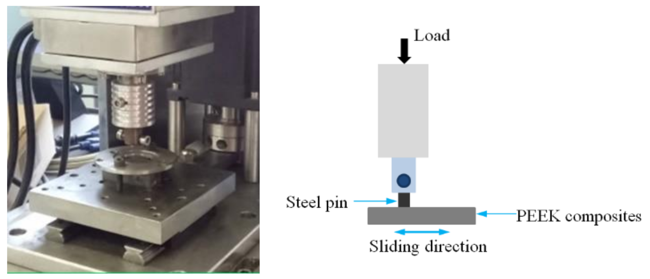
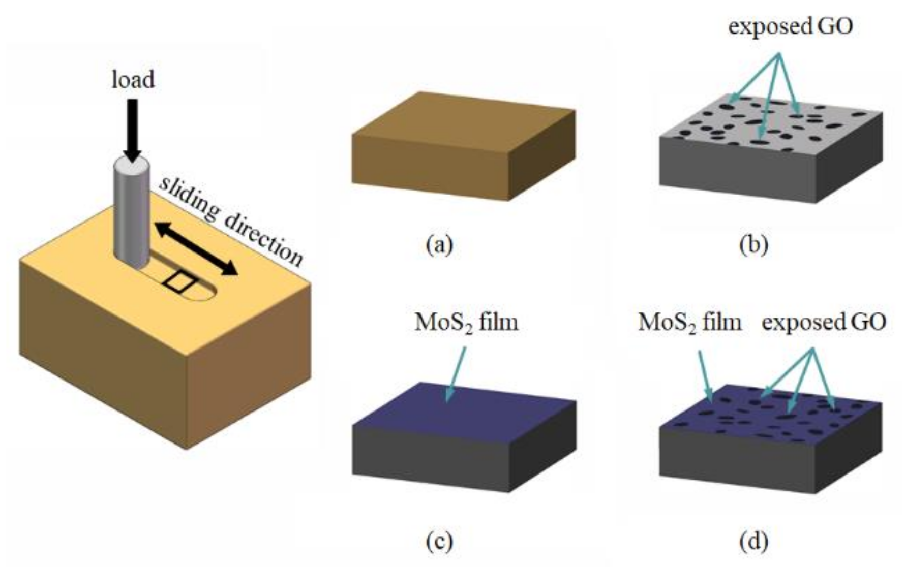
Tribological behaviors of composites were investigated on the commercial tribological tester (HSR-2M, Zhongke Kaihua Technology Development Co., Ltd., China) in a pin-on-flat configuration under reciprocation motion. The friction face of the composite was held in continuous sliding contact with the steel counterpart. The schematic diagram is shown in Figure 1. The upper specimen, i.e., the pin, was a 45 steel cylinder (a diameter of 3 mm, a length of 12 mm, and a roughness of Ra = 0.4 μm). The lower specimen, i.e., the flat, was a composites cuboid (a length of 20 mm, a width of 15 mm, a thickness of 10 mm, and a roughness of Ra = 0.6 μm). All tribological experiments had a duration of 20 min under constant normal load of 150 N, reciprocation frequency of 10 Hz, and stroke of 3 mm. They were conducted under conditions of dry sliding and room temperature. The normal load and friction force were measured by the sensors simultaneously during the tribological experiment. Then, the friction coefficients were calculated by expression μ = F/P, where μ is the friction coefficients, F is the friction force (N), and P is the normal load (N). The wear volume of composites was obtained by the measuring system of HSR-2M tribometer. Before each experiment, all steel pins and composites were ultrasonically cleaned with deionized water for 20 min at room temperature, to ensure the surface’s cleanliness. The wear rate K was calculated by expression K = ΔV/PS, where ΔV is the volume loss (mm3), P is the normal load (N), and S is the sliding distance (m). The experiments of each composite were carried out at in least three parallel experiments, to ensure a relevant statistical evaluation. The average value of friction coefficient and wear rate is presented in this work, with corresponding standard deviations. The worn surfaces of composites were inspected with SEM. Their three-dimensional morphologies were observed by a three-dimensional ultrafine optical microscope (Leica DVM6, Germany). Before examination, the samples were ultrasonically cleaned in the deionized water bath for 20 min, and then plated with a thin gold layer.
2.4. Mechanical Properties
The Vickers hardness was measured on planar composite samples by a THV-5 digital Vickers microhardness tester (Beijing Time High Technology Co., Ltd., Beijing, China) according to Chinese National Standard GB/T4340-2009. Before measuring, all sample surfaces were polished by a Masterlam polisher (Kulzer Lamplan, Gaillard, France), which was cleaned in distilled water for 20 min by ultrasonic cleaner. A standard Vickers indenter was utilized, with a load of 1.961 N for 15 s at room temperature. The indentation data were obtained by the Vickers hardness tester. Based on load and indentation data, the Vickers hardness was calculated from expression HV = 0.1891F/d2, where HV is the Vickers hardness, F is the test load (N), and d is the indentation diagonal arithmetic mean value (mm). The average value and standard deviation are presented in this work. Each composite sample was measured under at least five random positions.
Tensile testing was carried out by AG-XPLUS electronic universal testing machine (Shimatsu Manufacturing Co., Ltd., Kyoto, Japan) according to ASTM D3039M-14. Nominal dimensions of tensile composite sample were 50 mm in length, 5 mm in width, and 1mm in thickness. The sample had 12 mm smooth transition from gauge to 15 mm wide shoulders. Tests were carried out at a speed of 1 mm/min and at room temperature. Tensile strength was obtained using the calculating software of the testing machine. At least three samples of each composite were measured to obtain the average value and standard deviation. Fractography analysis was carried out on tensile fracture surfaces, which were coated with thin gold layer by sputtering device to give them electric conduction. The fracture surface morphology of composite was observed by SEM in the secondary electron mode at 10 kV. Representative fracture surfaces are shown.
2.5. Thermal Characterizations
Differential scanning calorimetry (DSC) tests were carried out using a Netzsch STA449F3, Germany. After 10 mg composite was pre-dried at 120 °C for 1 h, it was loaded into an aluminum pan, and heated from room temperature up to 400 °C at a heating rate of 20 °C/min under nitrogen atmosphere. The thermal gravimetric analysis (TGA) tests were conducted by a Pyris l, Perkin-Elmer, USA. The 5 mg dried samples were loaded into ceramic pans and heated up to 800 °C at a heating rate of 20 °C/min under nitrogen atmosphere. All composite samples were measured in triplicate.
3. Results
3.1. Tribological Behaviors
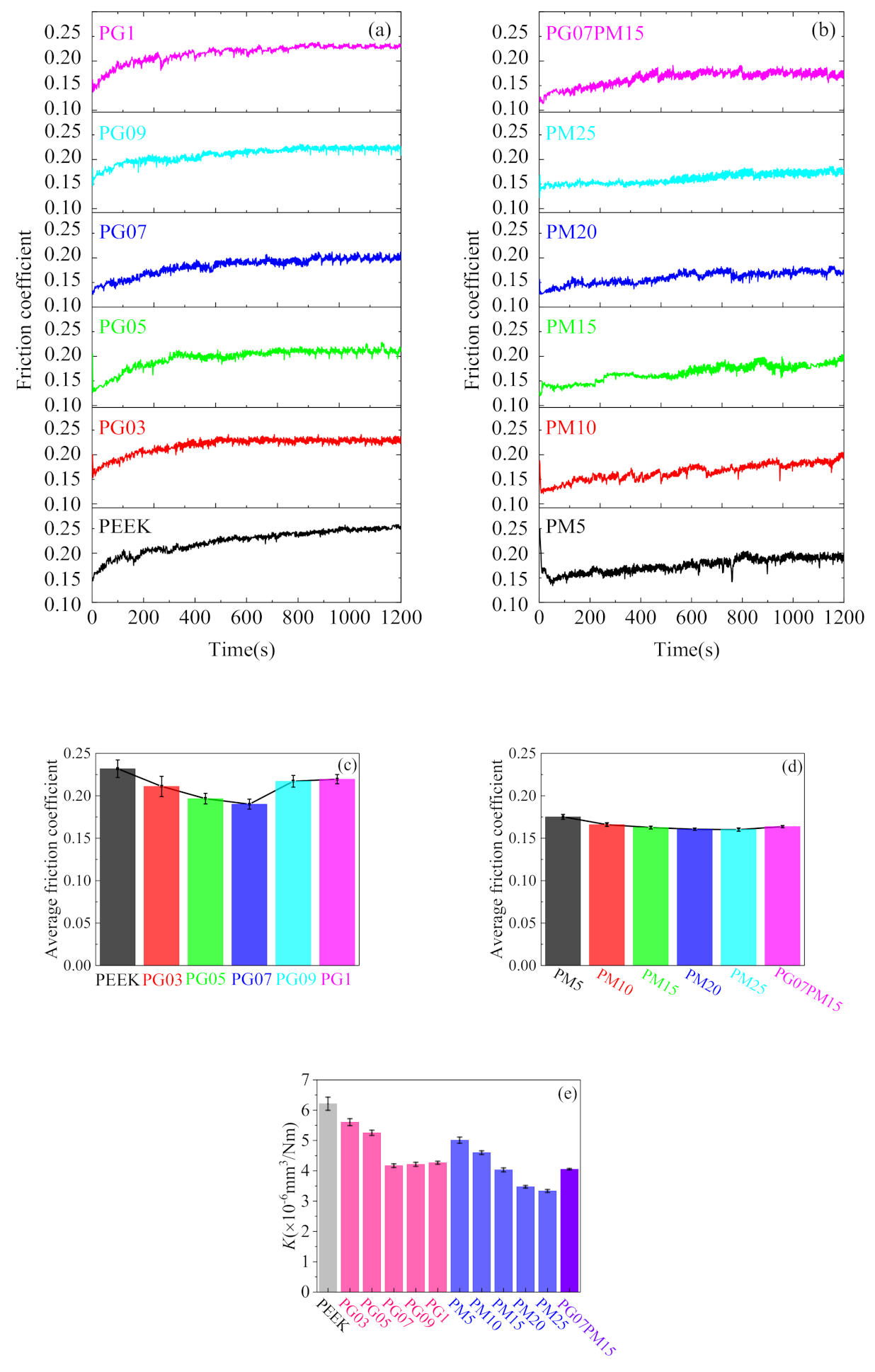
Friction coefficients of PEEK/GO and PEEK/MoS2 composites are shown in Figure 2. It can be clearly seen that the friction coefficient of PEEK and PEEK/GOs is gradually increasing and then fluctuating in a stable range (Figure 2a). The variation of average friction coefficient gradually decreases, and then increases with increasing of the GO content (Figure 2c). However, the average friction coefficient of all PEEK/GOs is lower than PEEK. The average friction coefficient of PEEK is 0.2319, suggesting PEEK has poor friction reduction capacity, which coincides with the results of Li et al. [33]. The PG05 has an average friction coefficient (μ) of 0.1966, reduced by 15% compared with PEEK. The PG07 has a minimum average friction coefficient of 0.1901, decreased by 18% compared with PEEK, indicating the best friction reduction abilities. When GO content exceeds 0.7 wt.%, the average friction coefficient begins to increase. For instance, PG09 has an average friction coefficient of 0.2171, which decreases by only 6% compared with PEEK; but the response time to a stable friction state is obviously different (Figure 2a). The response time of PEEK is about 950 s. However, the response time of PEEK/GOs reduces with increasing of the GO content. For example, the response time of PG03 is about 500 s, which reduces by 47% compared with PEEK, and the values of PG05 and PG07 are both about 400 s. The values of PG09 and PG1 decrease by 63% compared with PEEK. It is very important to reach stable friction state of friction pair quickly, which can greatly shorten the running-in time, reduce energy consumption, and improve the performance of composites. Meanwhile, it can be observed that the friction coefficient of PEEK/MoS2s and PEEK/GO/MoS2 is gradually increasing at the beginning of the experiment, and then fluctuating in a stable interval in Figure 2b. The response times of all PEEK/MoS2s are about 350 s and less than those of PEEK, indicating the MoS2 content has little effect on response time. It can be concluded that the MoS2 can effectively reduce the response time of PEEK/MoS2s. For PG07PM15, the response time is around 380 s, lower than that of PG07, but higher than that of PM15, which decreases by 60% compared with PEEK. The average friction coefficients of all PEEK/MoS2s decrease with the increasing of MoS2 content, i.e., the larger the MoS2 content, the smaller the average friction coefficient (Figure 2d). For example, the average friction coefficient of PM5 reduces 24% compared with PEEK. Moreover, the PM25 has a minimum average friction coefficient of 0.1602, which reduces by 31% compared with PEEK. However, the average friction coefficient does not result in a significant change when the MoS2 content exceeds 15 wt.%. For example, the average friction coefficient of PM15 is 0.1626, which decreases by 30% compared with PEEK. Nevertheless, the values of PM20 and PM25 only decrease by 30% and 31%, compared with PEEK, respectively. Furthermore, the average friction coefficient of PG07PM15 is 0.1637, which decreases by 14%, compared with PG07, and increases by 2% compared with PM15 (Figure 2d). Owing to low hardness, easy plastic deformation, and poor friction heat dissipation of PEEK, its high response time and average friction coefficient is mainly attributed to strong adhesion and plough effect on the rubbing surface [2,6,34]; however, the friction heat loss is improved and the adhesive effect is reduced for composites. On the other hand, GO and MoS2 play a key role in reducing friction coefficient of composites, owing to their self-lubrication. The better friction reduction of PEEK/MoS2 than PEEK/GO is attributed to the better self-lubrication of MoS2; however, the excessive GO leads to the increase of friction coefficient. This is due to the stress concentration and increased fragility, weakening the bonding strength between GO and PEEK matrix.
Figure 2e shows the variation of wear rate (K) of PEEK, PEEK/GOs, PEEK/MoS2s, and PEEK/GO/MoS2. The wear rate of PEEK is 6.213 × 10⁻⁶ mm3/Nm, which is in the same order of magnitude as the value obtained by Zhang et al. under a dry sliding condition [2]. The wear rate of PEEK/GOs significantly decreases, and then slightly fluctuates in a very small scale, with increasing of GO content. When the GO content increases from 0.5 wt.% to 0.7 wt.%, the wear rate obviously decreases. However, when the GO content exceeds 0.7 wt.%, the wear rate is basically constant. Regardless of the GO content, the wear rates of all PEEK/GOs are less than PEEK, indicating the positive effect of GO on the wear resistance. The wear rate of PG03 and PG05 reduces by 10% and 15% compared with PEEK, respectively. Nevertheless, PG07 has the lowest wear rate of 4.169 × 10⁻⁶ mm3/Nm, which decreases by 32.9 % compared with PEEK. In other words, PG07 has the best wear resistance. The variation in wear rate of PEEK/MoS2s obviously decreases with the increasing of MoS2 content. When the MoS2 content is less than 20 wt.%, the wear rate of PEEK/MoS2s approximately reduces linearly, whereas the difference in wear rate between PM20 and PM25 is minimal; however, the wear resistance of PEEK/MoS2s is significantly increased in comparison with PEEK. For instance, the PM5 has a maximum wear rate of K = 5.011 × 10⁻⁶ mm3/Nm, which decreases by 19% compared with PEEK; whereas PM25 has a minimum wear rate of 3.333 × 10⁻⁶ mm3/Nm, reduced by 46% compared with PEEK. The wear rate of PG07PM15 decreased by 35% compared with PEEK, which was almost equal to that of PM15 and less than that of PG07. It can be concluded that MoS2 plays a major role in the wear resistance of PG07PM15. It is worth noting that the abilities of friction reduction and wear resistance of the composites with both GO and MoS2 are not necessarily better than those of the composites with single GO or MoS2. The wear resistance and friction reduction of composite are attributed to the enhancement of its hardness, tensile strength, and thermal stability. On the other hand, the self-lubrication properties of GO and MoS2 also have positive effects on tribological behaviors.
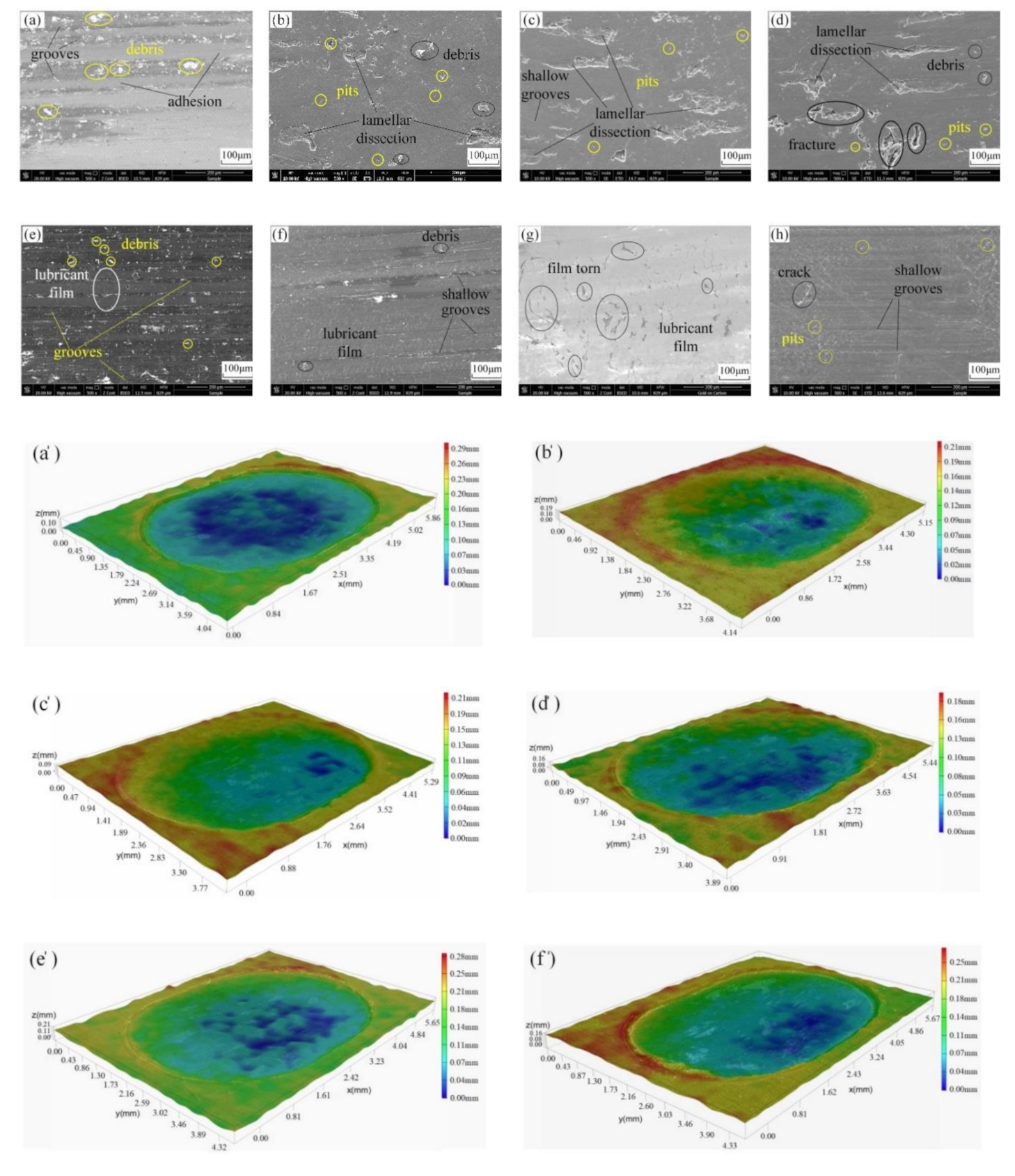
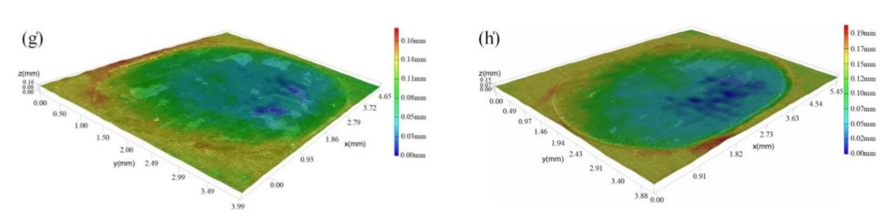
To facilitate the understanding of the friction and wear mechanism, representative SEM images and 3D optical morphologies of the worn surface of PEEK, PEEK/GOs, PEEK/MoS2s, and PG07PM15 are showed in Figure 3. The PEEK (Figure 3a,a’) exhibits uneven grooves parallel to the sliding direction and irregular removed material adhered back to the surface, which shows signs of abrasive wear and adhesive wear mechanism. Meanwhile, there are large amount of debris on the worn surface. The typical combination mechanism of abrasive wear and adhesive wear has been previously observed under a dry sliding condition [35]. A clear boundary is produced between the worn area and non-worn area, owing to PEEK stacking under the compressive load and friction force. The PEEK surface shows deep wear scratching. The worn surface is very rough, too. The worn surface of PG03 (Figure 3b,b’) is smoother than PEEK. It exhibits several very shallow grooves, lamellar dissection, fatigue fracture, short stripped pits, and wear debris, indicating wear characteristics of brittle materials to a certain extent. There are obvious partition boundaries similar with PEEK for PG03, PG07, and PG1. However, compared with PEEK, their wear depths are slighter (Figure 3c,d,c’,d’). Such characteristics may be attributed to the decrease of melting temperature of PEEK/GO, but the wear degree of the PEEK/GOs is obviously different. With increase of GO content, the fatigue wear becomes more and more dominant, and adhesive wear and abrasive wear gradually reduce. This indicates PEEK/GOs show signs of severe fatigue wear, adhesive wear, and mild abrasive wear. The PM5 (Figure 3e) represents more even grooves parallel to the sliding direction, plastic deformation, randomly adhered material, and wear debris. Nevertheless, the worn surface of PM15 (Figure 3f) exhibits a small quantity of shallow grooves, adhered material, and wear debris. Simultaneously, a water wave-like morphology is obviously observed. Similar to PEEK, the worn surfaces of PM5 and PM15 result from the same wear mechanism, i.e., mainly abrasive wear and adhesive wear, except the wear degree of individual components is different. Whereas in the case of PM25 (Figure 3g), the worn surface shows a completely different morphological feature from those of PM5 and PM15. It is very smooth and covered by an almost uniform and essentially continuous light gray layer. In addition, the gray layer can avoid direct contact between composites and counterpart, which further improves the tribological properties. It can be observed that there is very little adhesive material and plastic deformation on the worn surface, but no obvious grooves and wear debris. This indicates that PEEK/MoS2s possess better friction reduction and wear resistance compared to PEEK and PEEK/GOs. As shown in Figure 3e’,f’,g’, there are still obvious wear area boundaries. The accumulation of boundary materials is attributed to the plastic deformation of PEEK matrix. With increasing of MoS2 content, the wear depth reduces and the coverage rate of MoS2 film increases, which are due to the unique lubrication characteristics of MoS2. Furthermore, it is worth noting that MoS2 content has a positive contribution to wear resistance, i.e., the higher the MoS2 content, the better the wear resistance (Figure 2c). The PG07PM15 (Figure 3h,h’) represents very even, shallow, narrow grooves parallel to the sliding direction, a small quantity of microcracks, a water wave-like scratch, spalling pit, and plastic deformation. Its worn surface is smoother than those of PG07 and PM15. It can be observed that the worn surface shows neither the severe sheet spalling in the case of PG07, nor the deep grooves and wear debris in the case of PM15. Compared with other composites, a typical wear area boundary is observed in Figure 3h’. Such morphology features indicate that the wear mechanism of PG07PM15 is the combination of slight fatigue wear, mild abrasive wear, and adhesive wear. It can be concluded that the synergism between GO and MoS2 helps to form a good and tenacious lubricant film on the interface between composites and counterpart.
In order to better explain tribological behaviors of composites, Figure 4 presents a schematic diagram under a dry sliding condition. In the case of PEEK (Figure 4a), the grooves of worn surface are mostly due to the stiffness of counterpart of steel pin being much higher than that of PEEK. During the friction and wear process, the hard protuberances on the steel pin penetrate into the PEEK, and remove softer PEEK under applied contact load and friction shear. On account of the combination of the plastic deformation, delamination, and friction shear, PEEK is transferred to the counterpart surface to form a lubricant film. For the PEEK/GOs (Figure 4b), the wear characteristics may be due to the fact that the hardness and tensile strength of the composites is improved by addition of GO with large specific surface area and wrinkle, leading to less flow stress and considerably less plastic deformation for the sliding contact surface, as well as the decrease in the toughness of composites. Moreover, GO may agglomerate in the PEEK matrix, which is more likely to lead to the initiation of microcracks. Under the repeated stresses, the GO will be exposed gradually on the worn surface, carrying most of the applied load, promoting the formation of protective and in situ tribolayer on the interface between the composites and steel pin. These morphology features indicate that the addition of GO changes the main wear mechanism of composites from adhesive wear and abrasive wear to fatigue wear. The strong interface bonding of the composites make it difficult for GO to be detached from the PEEK matrix, and effectively improves the wear resistance of the composites. However, the lubricant films on the interface will be destroyed by desquamate caused by fatigue wear, as well as wear debris generated by fatigue wear. The abrasive wear is produced on the surface of composites by wear debris, which results in the shallow groove marks. Simultaneously, the wear debris plays a certain role in grinding composites, which makes its surface smooth. For PEEK/MoS2 (Figure 4c), the MoS2 is more easily released from the composites and exposed on the worn surface, owing to weaker bonding strength of MoS2 and PEEK matrix. More importantly, the MoS2 layered structure formed via weak van der Waals interactions between each layer gives better tribological performance, which makes it easier to form a continuous and complete lubricant layer between the interfaces. At the same time, the softer lubricant films can effectively cover the worn surface, fill the wear marks and the wear debris. This corresponds to the better friction reduction and wear resistance of PEEK/MoS2s in Figure 2b,c. However, for PG07PM15, GO and MoS2 would be concurrently exposed on the worn surface during the tribological test in Figure 4d. The GO with high mechanical strength can withstand load applied, and plays a certain role in lubrication and reduce composites from being further worn off, and then the MoS2 mostly plays the lubricant effect. In a word, the formed lubricant films provide a low-strength junction at the interface, resulting in lower friction coefficient and wear rate than PEEK. So, GO and MoS2 can effectively avoid direct touching of the friction pair surfaces, thus further inhibiting the wear of composites. However, the generated heat, which cannot be taken away as soon as possible, or dissipated during the process of friction, will lead to the further softening of the composites and the enhancement of adhesive wear. The effects of heat distribution and dissipation on performance are important [36]. In the meantime, the abrasive debris, difficultly discharged from the worn surface, will result in the inevitable abrasive wear under a dry sliding condition. On the contrary, the phenomenon of wear surface adhesion and a large amount of debris deposition are almost not observed, due to the presence of water lubrication [3].
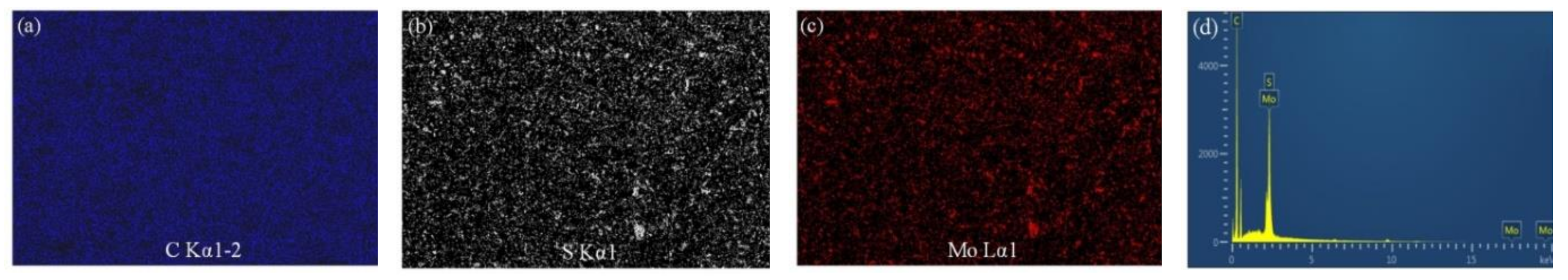
It is well known that the nanofillers have an inherent tendency to form agglomerates, due to the large surface area in the polymer matrix, and lead to decrease of the reinforcing effects [3,11,25,37]. The uniform distribution has an important effect on its hardness, tensile strength, and tribological properties. In order to evaluate the dispersion of GO and MoS2, the EDS analysis of element mapping was carried out for PG07PM15 in Figure 5. It can be clearly observed that MoS2 was evenly dispersed in the PEEK matrix, but, as PEEK and GO both are mainly composed of carbon, the distribution of GO in PEEK cannot be visually observed through EDS mapping images. It is hoped that another way or method can be explored in future research. This indicates that the hot isostatic pressing method used to prepare PEEK composites is reasonable and effective in this work, and the prepared composites could meet the experimental requirements.
3.2. Mechanical Properties
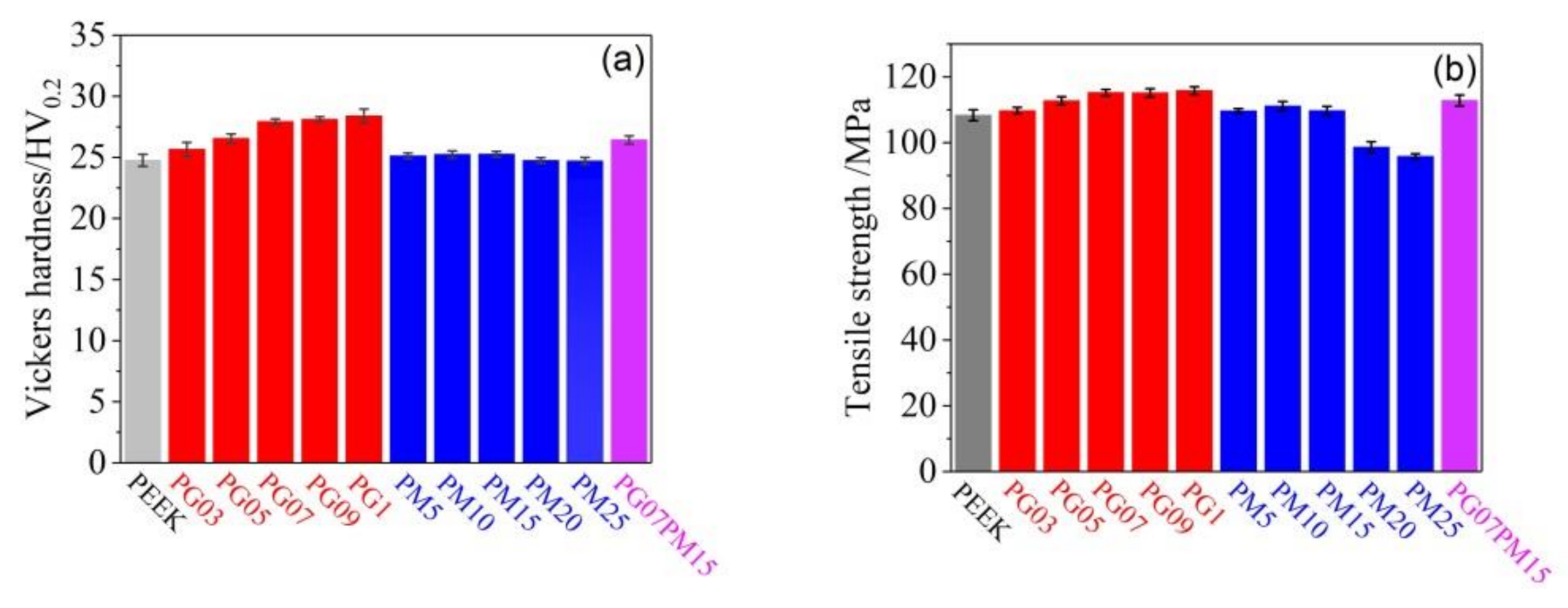
The tribological properties of a material are closely related to its hardness, which is always considered to represent the scratch resistance, abrasive resistance, and cutting resistance of the material surface [38,39]. To investigate the reason for the super wear performance of composites, the Vickers hardness and tensile strength of PEEK, PEEK/GOs, PEEK/MoS2s, and PEEK/GO/MoS2 are shown in Figure 6. As shown in Figure 6a, the Vickers hardness of PEEK/GOs increases with the increasing of GO content. The Vickers hardness of PG03 is 25.65 HV, and the value of PG1 reaches 28.39 HV, which is about 15% higher than that of PEEK. Interestingly, the Vickers hardness of PG07 is around 13% higher than that of PEEK, which is only 2% lower than that of PG1. This variation trend of the Vickers hardness of PEEK/GO is consistent with the reported results of Puértolas et al. [3] and Lin et al. [38]. It can be seen that the Vickers hardness of PEEK/MoS2s is gradually increased firstly, and then the Vickers hardness decreases after the MoS2 content beyond 15 wt.%. The PM15 is the largest, which is 25.26 HV, and it is about 2% higher than that of PEEK. PM20 and PM25 are almost the same as that of PEEK. This coincides with the results of Zalaznik et al. [25,40]. The Vickers hardness of PG07PM15 is around 1.1 times that of PEEK, and it is 26.42 HV. Interestingly, its Vickers hardness is 5% higher than that of PM15, but 6% lower than that of PG07, so this confirms that GO has a better effect on improving the Vickers hardness of composites than MoS2. The addition of GO or MoS2 could reinforce the formation of cross-networked structures and produce reorganization of amorphous polymer chains in composites, which provide a higher resistance against the normal load applied. The higher hardness of PEEK/GOs is related to the high hardness of GO [41]. The excellent hardness is beneficial to the tribological properties of composites, which coincides with the results of Figure 2.
In general, the tensile strength of a material has a close relationship with its tribological behaviors [2,3]. As shown in Figure 6b, the tensile strength of PEEK is 108.3 MPa, which is in agreement with Yang et al. [42]. The tensile strength of PEEK/GOs increases with increasing of GO content. When the content is lower than 0.7 wt.%, the tensile strength and GO content has a linear relationship. After that, the increment of tensile strength begins to decrease. The tensile strength of PG07 is 6% higher than that of PEEK, while PG1 is only 0.5% higher than that of PG07. Moreover, the introduction of GO could drastically affect the toughness of composites. The contribution of GO to the improvement of tensile strength is due to GO having good compatibility with PEEK and strong binding force, which improves the crystallinity and uniformity of PEEK matrix. However, when the GO content exceeds 0.7 wt.%, the tensile strength of the PEEK/GOs increases very little, due to the stress concentration caused by GO agglomeration. The tensile strength of PEEK/MoS2s increases firstly, and then decreases with the increasing of MoS2 content. The tensile strength of PM10 is 111.1 MPa, and it is 3% higher than that of PEEK. Interestingly, when the MoS2 content exceeds 15 wt.%, the tensile strength of PEEK/MoS2 is lower than that of PEEK. The tensile strength of PM25 decreases 12% compared with that of PEEK. It is worth noting that the MoS2 has a positive effect on the tensile strength of composites, but excessive content will have a negative effect. The lamellar structure of MoS2 causes shear slip of the composites under stress. The tensile strength of PG07PM15 is smaller than PG07 and higher than PEEK and PM15; its value reaches to 112.8 MPa, which coincides with the results of hardness. As stated above, GO is superior to MoS2 in improvement of tensile strength of PEEK matrix, which coincides with the results of Mittal et al. [43] and Puértolas et al. [3].
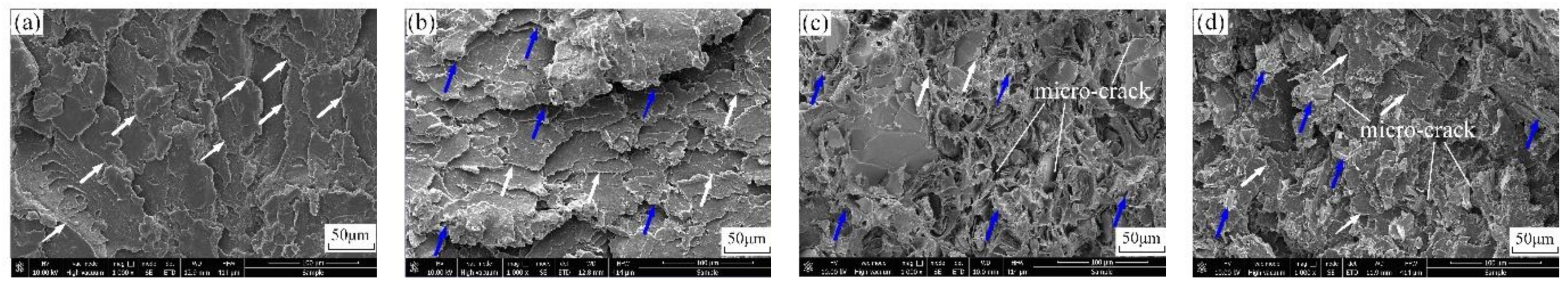
In order to investigate the fracture properties of composite, SEM images of fracture surface of the PEEK, PG07, PM15, and PG07PM15 after the tensile test are shown in Figure 7. The fracture surface of PEEK (Figure 7a) exhibits a relative smooth river and tongue pattern, in which ravines and penetrating cracks appear, but there is no obvious fracture dimple, fracture gully, and tearing shape, reflecting that PEEK has a typical brittle fracture mode due to high strain rate, and its tensile resistance is likely the fiber cracking and pill-out. For PG07 (Figure 7b), the fracture surface shows a relatively rough squamous-like morphology, on account of its brittleness, which is consistent with the decrease in toughness. The GO has good compatibility with PEEK matrix interface, which would cause crack deflection and disproportionation, could absorb tensile fracture energy, and hinder the crack propagation. Therefore, the tensile strength of PEEK/GO can be improved. In the case of PM15 (Figure 7c), the fracture surface exhibits a rougher morphology, with wrinkle and a large amount of sheet faults, in comparison with PEEK, which indicates more effective reinforcement of the toughness. The MoS2 are embedded in PEEK in its original layered structure, which is more likely to cause interlaminar slippage of the PEEK/MoS2. Meanwhile, the addition of MoS2 would destroy the continuity of PEEK matrix, and there are many microcracks around it, in which crack initiation and crack propagation are promoted. It coincides with the tensile strength of PEEK/MoS2. As shown in Figure 7d, the fracture surface of the PG07PM15 shows a relatively rougher morphology in comparison with that of PEEK, exhibiting different features in comparison with PG07 and PM15, which indicates that the presence of GO and MoS2 can dissipate much energy and hinder the crack propagation during the fracture process. It can be observed that there are wrinkles, stacked GO sheets (blue arrows in Figure 7), microvoids, and microcracks on the fracture surface. However, the obvious agglomeration phenomenon is not observed on the fracture surface, indicating a homogeneous dispersion of GO/MoS2 in the PEEK matrix. This coincides with the results of Vickers hardness and tensile strength.
3.3. Thermal Properties
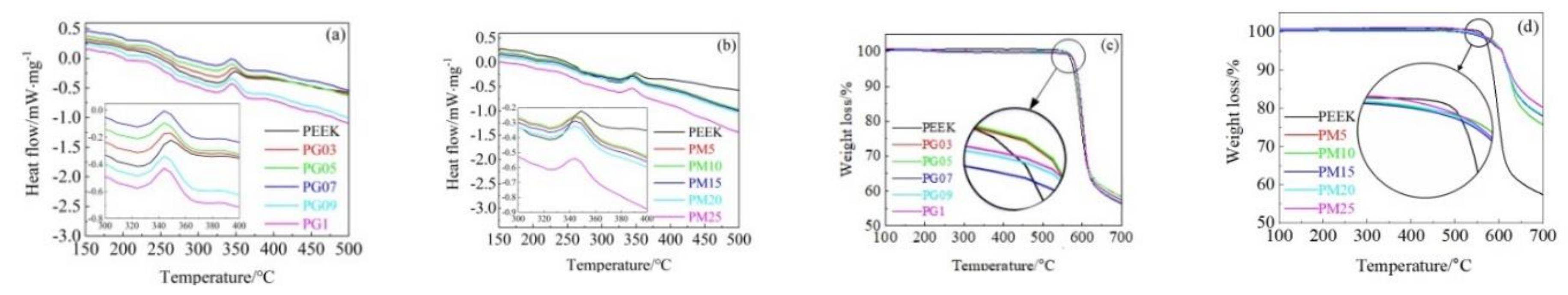
In order to further understand the super tribological performance of composites, the thermal behaviors are estimated. Figure 8 illustrates the DSC and TGA curves of PEEK, PEEK/GOs, and PEEK/MoS2s. As shown in Figure 8a, it can be observed that the melting temperature of PEEK, PG03, PG05, PG07, PG09, and PG1 is about 348.9 °C, 348.9 °C, 343.9 °C, 343.9 °C, 343.9 °C, and 343.9 °C, respectively. The decrease of melting temperature of PEEK/GO is attributed to the addition of GO. When the GO content exceeds 0.5 wt.%, the melting temperature is constant, and is 5 °C lower than that of PEEK. This coincides with the results of Puértolas et al. [3]. Interestingly, the melting temperatures of all PEEK/MoS2s are almost the same, their values are all around 343.9 °C, and lower than that of PEEK in the Figure 8b, which coincides with the results reported by Zalaznik et al. [25]. It is worth noting that the MoS2 content has no significant effect on the melting temperature. The reason is because the addition of MoS2 or GO destroys the continuity of PEEK matrix, and the motion of the polymer chain is segmented during crystallization (white arrows in Figure 7), which inhibits molecular stacking (blue arrows in Figure 7) and results in the formation of less-perfect crystallites. As shown in Figure 8c, the PEEK/GOs exhibit a similar thermal decomposition process with PEEK, which can be mainly ascribed to the decomposition of PEEK polymer molecular chains. The onset decomposition temperature of PEEK/GOs increases with the increasing of GO content. The onset decomposition temperature and weight residue of PEEK are approximately 578 °C and 56%, respectively. Compared to PEEK, for lower GO content, i.e., PG03 and PG05, the thermal decomposition temperature improves by 5 °C, while that of PG07, PG09, and PG1 improves by about 10 °C. In consequence, it can be seen that GO can effectively increase the thermal stability of composites, and PEEK/GOs have higher thermal stability with increasing GO content. It is observed that PEEK/MoS2s exhibit a different thermal decomposition process to the PEEK (Figure 8d), which can be ascribed to the barrier effect of MoS2 on the diffusion of PEEK. The decomposition temperature of PM5 and PM10 is approximately 603 °C. Nevertheless, the decomposition temperature of composites reaches 608 °C when the MoS2 content exceeds 15 wt.%. It is higher than PEEK by about 25–30 °C. It indicates that the presence of MoS2 can effectively enhance the thermal stability of PEEK matrix. The thermal properties of composites are in relation with combined morphology between GO or/and MoS2 and PEEK matrix (Figure 7). However, the weight residue of PM5, PM10, PM15, PM20, and PM25 is 74%, 74%, 76%, 77%, and 79%, respectively. Compared with PEEK, the weight residue increases 32~41%. Similar observations were reported by Chen et al. [12] and Gong et al. [44]. Therefore, it can be seen that the MoS2 can obviously promote the thermal stability of composites. Furthermore, it can be worth noting that the effect of MoS2 on the thermal stability of composites is better than GO. This is mainly attributed to MoS2‘s excellent high temperature resistance and the interaction between PEEK matrix, which results in the formation of a stable network structure within the composites, preventing the PEEK chain segments (white arrows in Figure 7) from decomposition at high temperature [7,45]. In addition, the charring effect of MoS2 at high temperature also contributes to the thermal stability of composites. It is well known that a large amount of heat will be generated during the process of friction and wear, especially under dry friction conditions [46], and it will lead to excessive degradation of the polymer and poor tribological properties. Therefore, the excellent thermal stability of composites effectively prevents the high temperature harm, and improves their tribological performances in dry sliding friction and wear conditions.
4. Conclusions
In this study, PEEK/GO and PEEK/MoS2 composites were successfully prepared via a novel hot isostatic press method. The mapping-mode EDS shows that the MoS2 are evenly distributed in PEEK matrix. The wear rate of PEEK/GOs, PEEK/MoS2s, and PEEK/GO/MoS2 are obviously reduced. The reduction of response time to stable friction state is due to the addition of GO and MoS2, and it obviously decreases with increasing of the GO content. In addition, the addition of GO and MoS2 effectively decreases the friction coefficient of PEEK matrix. PEEK exhibits a typical combination of abrasive wear and adhesive wear mechanism. The severe fatigue wear, light adhesive wear, and mild abrasive wear mechanisms are found for PEEK/GO, and the fatigue wear severity increases with increasing of GO content. However, the PEEK/MoS2 shows abrasive wear and little adhesive wear mechanism, and this is related to MoS2 content. The wear mechanism of GO/PEEK/MoS2 is mostly slight fatigue wear, mild abrasive wear, and adhesive wear.
Author Contributions
Conceptualization: Y.Y. and Y.H.; methodology: Y.Y.; investigation: Y.Y., C.J., and C.L.; writing—original draft preparation: Y.Y.; writing—review and editing: Y.Y. and Y.H.; funding acquisition: Y.Y. All authors have read and agreed to the published version of the manuscript.
Funding
This research was funded by National Natural Science Foundation of China, grant number 51875095.
Conflicts of Interest
The authors declare no conflict of interest.
References
- Kumar, D.; Rajmohan, T.; Venkatachalapathi, S. Wear behavior of PEEK matrix composites: A review. Mater. Today Proc. 2018, 5, 14583–14589. [Google Scholar] [CrossRef]
- Zhang, Z.; Breidt, C.; Chang, L.; Friedrich, K. Wear of PEEK composites related to their mechanical performances. Tribol. Int. 2004, 37, 271–277. [Google Scholar] [CrossRef]
- Puértolas, J.A.; Castro, M.; Morris, J.A.; Ríos, R.; Ansón-Casaos, A. Tribological and mechanical properties of graphene nanoplatelet/PEEK composites. Carbon 2019, 141, 107–122. [Google Scholar] [CrossRef] [Green Version]
- Jahan, M.S.; Walters, B.M.; Riahinasab, T.; Gnawali, R.; Adhikari, D.; Trieu, H. A comparative study of radiation effects in medical-grade polymers: UHMWPE, PCU and PEEK. Radiat. Phys. Chem. 2016, 118, 96–101. [Google Scholar] [CrossRef]
- Zhu, J.J.; Ma, L.; Dwyer-Joyce, R. Friction and wear behaviours of self-lubricating peek composites for articulating pin joints. Tribol. Int. 2020, 149, 105741. [Google Scholar] [CrossRef]
- Song, H.J.; Li, N.; Li, Y.J.; Min, C.Y.; Wang, Z. Preparation and tribological properties of graphene/poly(ether ether ketone) nanocomposites. J. Mater. Sci. 2012, 47, 6436–6443. [Google Scholar] [CrossRef]
- Chen, Z.Y.; Yan, H.X.; Liu, T.Y.; Niu, S. Nanosheets of MoS2 and reduced graphene oxide as hybrid fillers improved the mechanical and tribological properties of bismaleimide composites. Compos. Sci. Technol. 2016, 125, 47–54. [Google Scholar] [CrossRef]
- Sharma, M.; Bijwe, J.; Mitschang, P. Wear performance of PEEK-carbon fabric composites with strengthened fiber-matrix interface. Wear 2011, 271, 2261–2268. [Google Scholar] [CrossRef]
- Tewatia, A.; Hendrix, J.; Dong, Z.Z.; Taghon, M.; Tse, S.; Chiu, G.; Mayo, W.E.; Kear, B.; Nosker, T.; Lynch-Branzoi, J.K. Characterization of melt-blended graphene—Poly(ether ether ketone) nanocomposite. Mater. Sci. Eng. B 2017, 216, 41–49. [Google Scholar] [CrossRef] [Green Version]
- Cao, Z.S.; Qiu, L.; Yang, Y.Z.; Chen, Y.K.; Liu, X.G. The surface modifications of multi-walled carbon nanotubes for multi-walled carbon nanotube/poly(ether ether ketone) composites. Appl. Surf. Sci. 2015, 353, 873–881. [Google Scholar] [CrossRef] [Green Version]
- Kuo, M.C.; Tsai, C.M.; Huang, J.C.; Chen, M. PEEK composites reinforced by nano-sized SiO2 and Al2O3 particulates. Mater. Chem. Phys. 2005, 90, 185–195. [Google Scholar] [CrossRef]
- Chen, B.B.; Li, X.; Jia, Y.H.; Li, X.F.; Yang, J.; Yan, F.Y.; Li, C.S. MoS2 nanosheets-decorated carbon fiber hybrid for improving the friction and wear properties of polyimide composite. Compos. Part A Appl. Sci. Manuf. 2018, 109, 232–238. [Google Scholar] [CrossRef]
- Rinaldi, M.; Puglia, D.; Dominici, F.; Cherubini, V.; Torre, L.; Nanni, F. Melt processing and mechanical property characterization of high-performance poly(ether ether ketone)-carbon nanotube composite. Polym. Int. 2017, 66, 1731–1736. [Google Scholar] [CrossRef]
- Wahab, Z.; Marsh, Z.M.; Tessema, A.; Kidane, A.; Stefik, M.; Anneaux, B.L.; Ploehn, H.J. Effect of Nanodiamond (ND) Surface Functionalization on the Properties of ND/PEEK Composites. IEEE Trans. Compon. Packag. Manuf. Technol. 2017, 7, 165–177. [Google Scholar] [CrossRef]
- Novoselov, K.S.; Geim, A.K.; Morozov, S.V.; Jiang, D.; Zhang, Y.; Dubonos, S.V.; Grigorieva, I.V.; Firsov, A.A. Electric Field Effect in Atomically Thin Carbon Films. Science 2004, 306, 666–669. [Google Scholar] [CrossRef] [Green Version]
- Clavería, I.; Elduque, D.; Lostalé, A.; Fernández, Á.; Castell, P.; Javierre, C. Analysis of self-lubrication enhancement via PA66 strategies: Texturing and nano-reinforcement with ZrO2 and graphene. Tribol. Int. 2019, 131, 332–342. [Google Scholar] [CrossRef]
- Wang, F.; Wang, H.Y.; Mao, J. Aligned-graphene composites: A review. J. Mater. Sci. 2019, 54, 36–61. [Google Scholar] [CrossRef]
- Yetgin, S.H. Tribological properties of compatabilizer and graphene oxide-filled polypropylene nanocomposites. Bull. Mater. Sci. 2020, 43, 89. [Google Scholar] [CrossRef]
- Roy, A.; Mu, L.W.; Shi, Y.J. Tribological properties of polyimide-graphene composite coatings at elevated temperatures. Prog. Org. Coat. 2020, 142, 105602. [Google Scholar] [CrossRef]
- Kandanur, S.S.; Rafiee, M.A.; Yavari, F.; Schrameyer, M.; Yu, Z.-Z.; Blanchet, T.A.; Koratkar, N. Suppression of wear in graphene polymer composites. Carbon 2012, 50, 3178–3183. [Google Scholar] [CrossRef]
- Pan, B.L.; Zhao, J.; Zhang, Y.Q.; Zhang, Y.Z. Wear Performance and Mechanisms of Polyphenylene Sulfide/Polytetrafluoroethylene Wax Composite Coatings Reinforced by Graphene. J. Macromol. Sci. Part B Phys. 2012, 51, 1218–1227. [Google Scholar] [CrossRef]
- Agrawal, N.; Parihar, A.S.; Singh, J.P.; Goswami, T.H.; Tripathi, D.N. Efficient nanocomposite formation of acrylo nitrile rubber by incorporation of graphite and graphene layers: Reduction in friction and wear rate. Procedia Mater. Sci. 2015, 10, 139–148. [Google Scholar] [CrossRef] [Green Version]
- Surya, R.B.; Balaji, S.; Mohamed, A.N.A.B. Tribological performance of graphene/graphite filled phenolic composites—A comparative study. Compos. Commun. 2019, 15, 34–39. [Google Scholar]
- Chih, A.; Ansón-Casaos, A.; Puértolas, J.A. Frictional and mechanical behaviour of graphene/UHMWPE composite coatings. Tribol. Int. 2017, 116, 295–302. [Google Scholar] [CrossRef]
- Zalaznik, M.; Novak, S.; Huskic, M.; Kalin, M. Tribological behaviour of a PEEK polymer containing solid MoS2 lubricants. Lubr. Sci. 2015, 28, 27–42. [Google Scholar] [CrossRef]
- Wu, H.X.; Yin, S.C.; Du, Y.; Wang, L.P.; Wang, H.F. An investigation on the lubrication effectiveness of MoS2 and BN layered materials as oil additives using block-on-ring tests. Tribol. Int. 2020, 151, 106516. [Google Scholar] [CrossRef]
- Bhardwaj, V.; Pandeyb, R.K.; Agarwal, V.K. Experimental investigations for tribo-dynamic behaviours of conventional and textured races ball bearings using fresh and MoS2 blended greases. Tribol. Int. 2017, 113, 149–168. [Google Scholar] [CrossRef]
- Yi, M.R.; Zhang, C.H. The synthesis of MoS2 particles with different morphologies for tribological applications. Tribol. Int. 2017, 116, 285–294. [Google Scholar] [CrossRef]
- Tang, G.G.; Zhang, J.; Liu, C.C.; Zhang, D.; Wang, Y.Q.; Tang, H.; Li, C.S. Synthesis and tribological properties of flower-like MoS2 microspheres. Ceram. Int. 2014, 40, 11575–11580. [Google Scholar] [CrossRef]
- Hu, K.H.; Hu, X.G.; Wang, J.; Xu, Y.F.; Han, C.L. Tribological Properties of MoS2 with Different Morphologies in High-Density Polyethylene. Tribol. Lett. 2012, 47, 79–90. [Google Scholar] [CrossRef]
- Zhang, S.-B.; Yan, Y.T.; Huo, Y.Q.; Yang, Y.; Feng, J.L.; Chen, Y.F. Electrochemically reduced graphene oxide and its capacitance performance. Mater. Chem. Phys. 2014, 148, 903–908. [Google Scholar] [CrossRef]
- Yan, Y.T.; Li, C.F.; Wang, D.; Li, Y.; Zhang, T.L. A Novel Hot Isostatic Pressing Device. Chinese Patent ZL201810031099. X, 9 November 2019. [Google Scholar]
- Li, E.Z.; Guo, W.L.; Wang, H.D.; Xu, B.S.; Liu, X.T. Research on Tribological Behavior of PEEK and Glass Fiber Reinforced PEEK Composite. Phys. Procedia 2013, 50, 453–460. [Google Scholar] [CrossRef] [Green Version]
- Bijwe, J. Potential of fibers and solid lubricants to enhance the tribo-utility of PEEK in adverse operating conditions. Ind. Lubr. Tribol. 2007, 59, 156–165. [Google Scholar] [CrossRef]
- Kalin, M.; Zalaznik, M.; Novak, S. Wear and friction behaviour of poly-ether-ether-ketone (PEEK) filled with graphene, WS2 and CNT nanoparticles. Wear 2015, 332, 855–862. [Google Scholar] [CrossRef]
- Saxena, P.; Gorji, N.E. COMSOL Simulation of Heat Distribution in Perovskite Solar Cells: Coupled Optical–Electrical–Thermal 3-D Analysis. IEEE J. Photovolt. 2019, 9, 1693–1698. [Google Scholar] [CrossRef]
- Chatterjee, S.; Nafezarefi, F.; Tai, N.H.; Schlagenhauf, L.; Nüesch, F.A.; Chu, B.T.T. Size and synergy effects of nanofiller hybrids including graphene nanoplatelets and carbon nanotubes in mechanical properties of epoxy composites. Carbon 2012, 50, 5380–5386. [Google Scholar] [CrossRef]
- Lin, Q.; Qu, L.; Lü, Q.F.; Fang, C.Q. Preparation and properties of grapheme oxide nanosheets/cyanate ester resin composites. Polym. Test. 2013, 32, 330–337. [Google Scholar] [CrossRef]
- Lin, Q.L.; Zheng, R.G.; Tian, P.H. Preparation and characterization of BMI resin/graphite oxide nanocomposites. Polym. Test. 2010, 29, 537–543. [Google Scholar] [CrossRef]
- Zalaznik, M.; Kalin, M.; Novak, S.; Jakša, G. Effect of the type, size and concentration of solid lubricants on the tribological properties of the polymer PEEK. Wear 2016, 364–365, 31–39. [Google Scholar] [CrossRef]
- Zhang, X.R.; Pei, X.Q.; Wang, Q.H. Friction and wear studies of polyimide composites filled with short carbon fibers and graphite and micro SiO2. Mater. Des. 2009, 30, 4414–4420. [Google Scholar] [CrossRef]
- Yang, L.L.; Zhang, S.L.; Chen, Z.; Guo, Y.L.; Luan, J.S.; Geng, Z.; Wang, G.B. Design and preparation of graphene/poly(ether ether ketone) composites with excellent electrical conductivity. J. Mater. Sci. 2013, 49, 2372–2382. [Google Scholar] [CrossRef]
- Mittal, V.; Chaudhry, A.U. Polymer-graphene nanocomposites: Effect of polymer matrix and filler amount on properties. Macromol. Mater. Eng. 2015, 300, 510–521. [Google Scholar] [CrossRef]
- Gong, K.L.; Wu, X.H.; Zhao, G.Q.; Wang, X.B. Nanosized MoS2 deposited on graphene as lubricant additive in polyalkylene glycol for steel/steel contact at elevated temperature. Tribol. Int. 2017, 110, 1–7. [Google Scholar] [CrossRef]
- Lai, Y.H.; Kuo, M.C.; Huang, J.C.; Chen, M. On the PEEK composites reinforced by surface-modified nano-silica. Mater. Sci. Eng. A 2007, 458, 158–169. [Google Scholar] [CrossRef] [Green Version]
- Chen, B.B.; Li, X.; Jia, Y.H.; Xu, L.; Liang, H.Y.; Li, X.F.; Yang, J.; Li, C.S.; Yan, F.Y. Fabrication of ternary hybrid of carbon nanotubes/graphene oxide/MoS2 and its enhancement on the tribological properties of epoxy composite coatings. Compos. Part A Appl. Sci. Manuf. 2018, 115, 157–165. [Google Scholar] [CrossRef]
Figure 1.
Schematic diagram of the pin-on-flat contact configuration of reciprocation sliding friction apparatus.
Figure 1.
Schematic diagram of the pin-on-flat contact configuration of reciprocation sliding friction apparatus.

Figure 2.
Friction coefficient of poly-ether-ether ketone (PEEK) and PEEK/graphene oxides (GOs) (a,c), PEEK/MoS2s and PEEK/GO/MoS2 (b,d), and wear rate of PEEK, PEEK/GOs, PEEK/MoS2s, and PEEK/GO/MoS2 (e).
Figure 2.
Friction coefficient of poly-ether-ether ketone (PEEK) and PEEK/graphene oxides (GOs) (a,c), PEEK/MoS2s and PEEK/GO/MoS2 (b,d), and wear rate of PEEK, PEEK/GOs, PEEK/MoS2s, and PEEK/GO/MoS2 (e).

Figure 3.
SEM images and 3D optical morphologies of worn surfaces. (a,a’) PEEK, (b,b’) PG03, (c,c’) PG07, (d,d’) PG1, (e,e’) PM5, (f,f‘) PM15, (g,g’) PM25, (h,h’) PG07PM15.
Figure 3.
SEM images and 3D optical morphologies of worn surfaces. (a,a’) PEEK, (b,b’) PG03, (c,c’) PG07, (d,d’) PG1, (e,e’) PM5, (f,f‘) PM15, (g,g’) PM25, (h,h’) PG07PM15.


Figure 4.
Schematic illustration of friction and wear of PEEK (a), PEEK/GOs (b), PEEK/MoS2s (c), and PEEK/GO/MoS2 (d).
Figure 4.
Schematic illustration of friction and wear of PEEK (a), PEEK/GOs (b), PEEK/MoS2s (c), and PEEK/GO/MoS2 (d).

Figure 5.
EDS mapping images of PG07PM15. (a) C, (b) S, (c) Mo and (d) element scale diagram

Figure 6.
(a) Vickers hardness and (b) tensile strength of PEEK, PEEK/GOs, PEEK/MoS2s, and PEEK/GO/MoS2.
Figure 6.
(a) Vickers hardness and (b) tensile strength of PEEK, PEEK/GOs, PEEK/MoS2s, and PEEK/GO/MoS2.

Figure 7.
SEM images of fracture surfaces (a) PEEK, (b) PG07, (c) PM15, and (d) PG07PM15.

Figure 8.
DSC and TGA curves of (a,b) PEEK and PEEK/GOs and (c,d) PEEK and PEEK/MoS2s.

Publisher’s Note: MDPI stays neutral with regard to jurisdictional claims in published maps and institutional affiliations. |
© 2020 by the authors. Licensee MDPI, Basel, Switzerland. This article is an open access article distributed under the terms and conditions of the Creative Commons Attribution (CC BY) license (http://creativecommons.org/licenses/by/4.0/).
Share and Cite
MDPI and ACS Style
Yan, Y.; Jiang, C.; Huo, Y.; Li, C. Preparation and Tribological Behaviors of Lubrication-Enhanced PEEK Composites. Appl. Sci. 2020, 10, 7536. https://doi.org/10.3390/app10217536
AMA Style
Yan Y, Jiang C, Huo Y, Li C. Preparation and Tribological Behaviors of Lubrication-Enhanced PEEK Composites. Applied Sciences. 2020; 10(21):7536. https://doi.org/10.3390/app10217536
Chicago/Turabian StyleYan, Yutao, Cheng Jiang, Yuqiu Huo, and Chaofeng Li. 2020. "Preparation and Tribological Behaviors of Lubrication-Enhanced PEEK Composites" Applied Sciences 10, no. 21: 7536. https://doi.org/10.3390/app10217536
Note that from the first issue of 2016, this journal uses article numbers instead of page numbers. See further details here.