A Novel Sediment Pressure Sampling Device Carried by a Hadal-Rated Lander


Ocean College, Zhejiang University, Zhoushan 316021, China
*
Author to whom correspondence should be addressed.
J. Mar. Sci. Eng. 2020, 8(11), 839; https://doi.org/10.3390/jmse8110839
Submission received: 16 September 2020
/
Revised: 22 October 2020
/
Accepted: 23 October 2020
/
Published: 24 October 2020
(This article belongs to the Section Ocean Engineering)
Abstract
:Reliable sampling technology for deep-sea sediments is a prerequisite for studying the sedimentary environment in the geological history, the mechanical characteristics of sediments and sediment biology. In this study, we develop a new sampling device in order to achieve a convenient and economic pressure sampling for hadal sediments. The overall structure, as well as the key component such as the pressure-holding part, and the sealing structure are designed. The feasibility of the device was verified through field tests. Furthermore, the sampling process is analyzed by the computer simulation. It is found that the sampling length is determined by the open diameter and the installation position of the core keepers. According to the simulation, the structure is optimized, which is beneficial to the further improvement of the sampling length.
1. Introduction
In the ocean, the sea area with a depth of more than 6000 m is called the hadal sea area, and the sediments in this sea area are called hadal sediments. Humans currently have done little exploration of this area. The hadal sediments usually have some unique characteristics that scientists want to study. Reliable sampling technology for the deep-sea sediment is a prerequisite for scientific research on marine ecological environment, marine geology, biogeochemical cycles, global environment and ancient environment. The sedimentary environment in geological history, the mechanical characteristics of sediments, the microorganisms required by modern medicine and the changing marine environment can be understood by the analysis of the sediment [1,2].
Pressure samplers can provide the most pristine state of the sediment, so that the sampling and study of deep-sea sediment has a wide range of scientific significance. At present, a variety of samplers can be used to obtain deep-sea sediment at pressure [3]. The development of Chinese deep-sea sediment sampling devices in China started in the 1970s and progressed rapidly in the 21st century [4]. In 1983 the Ocean Drilling Program (ODP) developed the first Pressure Core Barrel (PCB), and in the following five years, three generations of PCB were developed, with the final version of PCB III being successfully tested on the 76th voyage and successfully deployed three times on the 84th voyage, in which the gas volume was successfully measured for the first time [5]. Dicken designed the famous Pressure Core Sampler (PCS), which is a free-falling, hydraulic-driven, cable-recovered pressure-holding sampler [6,7]. Amann et al. developed a new autoclave coring device based on their experience with PCS during the ODP for drilling and recovering sediments containing water. In the HYACINTH project funded by the European Union, two pressure coring systems have also been developed, namely the Fugro Pressure Corer (FPC) and the HYACE Rotary Corer (HRC). The FPC is mainly designed for sampling soft and hard clays, while the HRC is mainly designed for sampling cuttings sediments or rocks [8]. The Pressure Temperature Corer System (PTCS) was developed by Japanese National Petroleum, Natural Gas and Metal Corporation and deployed in the South China Sea. Geotechnical Co., Ltd. in Tokyo, Japan, has developed a Pressure Core Analysis and Transmission System (PCATS), which can be used to analyze pressure core samples under in-situ pressure. Subsequently, a new pressure coring sampling tool was developed, namely the Hybrid-pressure Coring System (Hybrid-PCS), in which the autoclave is connected to the PCATS without releasing the in-situ pressure [9,10,11]. Abegg et al. invented two coring devices for sampling sediments that contain near-surface natural gas and gas hydrates [12]. The first coring tool, the Multiple Autoclave Corer (MAC), resembles a standard multiple corer in terms of applications, size and core length of about 55 cm. The second tool, the Dynamic Autoclave Piston Corer (DAPC), is similar to a piston corer in application and size and enables one to take cores of up to 2.5 m length [13]. Chen et al. invented a gravity piston core sampler that can obtain 30 m long in-situ sediments that contain natural gas hydrate, which is an improvement of the traditional piston core sampler [14]. Luo et al. proposed a corer based on an in-situ drilling fluid ice valve, and a series of preliminary experiments were carried out on the ice valve for the pressure corer [15]. The study found that the ice valve is not sensitive to solid particles and rust, so the pressure sediment device based on ice valve is an effective way to improve the core rate of sediments that contain natural gas hydrate.
Most of the current pressure sampling devices require a power source, including a hydraulic drive, a manipulator operation. While the gravity piston sampler works without the power source, the bottom end surface is sealed with a plate valve, which increases the device size and weight a lot, so that it can only be deployed independently and cannot be installed on a lander. In this study, we develop a pressure sampling device, which is of small size and light weight. Meanwhile, it has its own power source, and can be worked independently. This sampling device is planned to be installed on a lander of Shanghai Ocean University to do sea trials in the Mariana Trench. Due to the limitations of the equipment, this device is mainly used for the sampling of soft sediments, and ensure that the pressure loss does not exceed 20%.
2. Design of Sampling Device
2.1. The Overall Structure
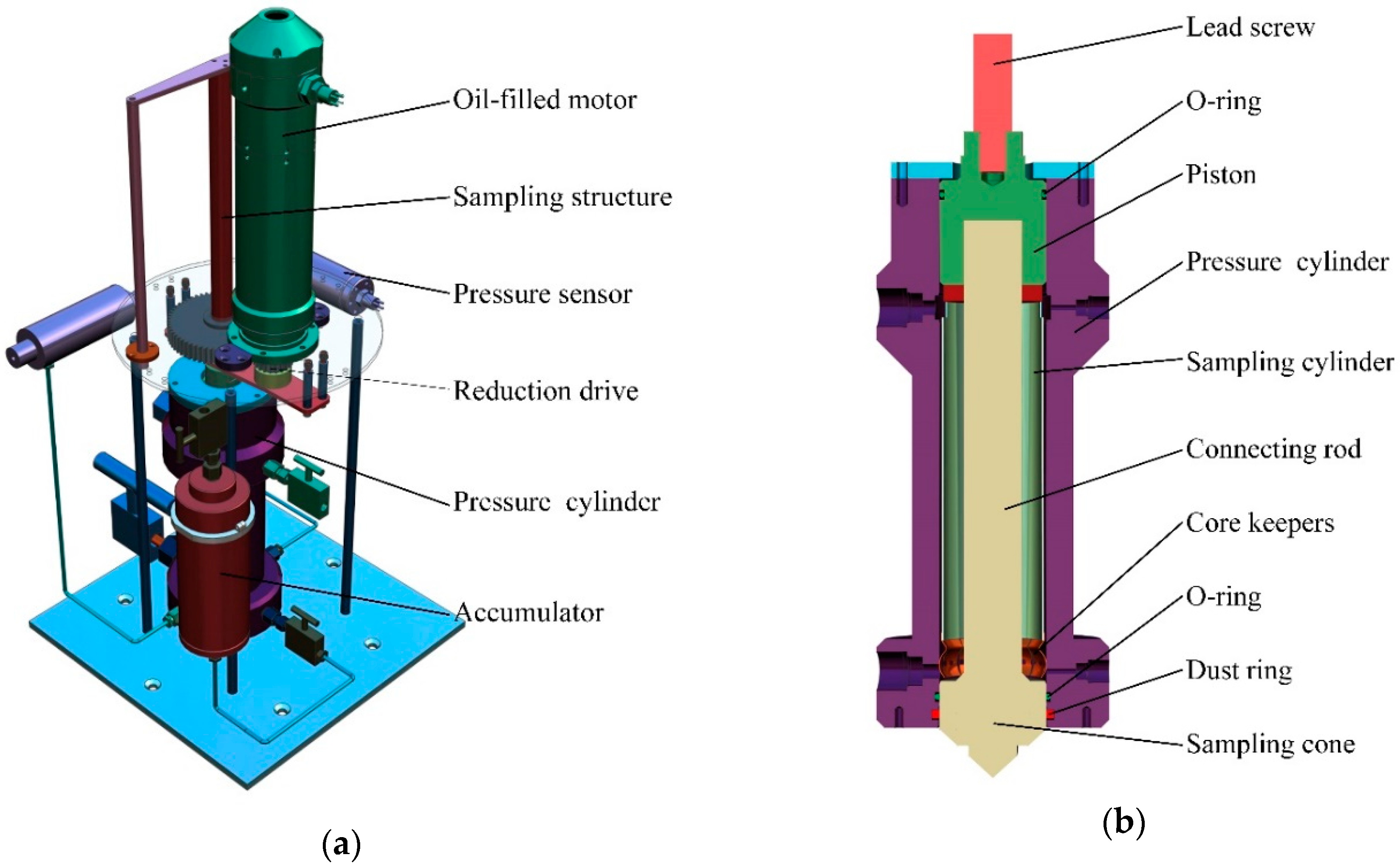
This device installed on a lander is mainly used for the sampling of hadal sediments, it is a new method of pressure sampling and is currently at a prototype stage, and the structure of the device is shown in Figure 1a. The device is mainly composed of an oil-filled motor, a reduction drive structure, a screw drive structure, a sampling structure, a pressure cylinder, an accumulator, a pressure sensor, and high pressure needle valves.
The oil-filled motor is a servo motor. Considering that the normal servo motor cannot work properly under water, a motor shell is processed and the shell is filled with oil. This way the servo motor is always in the oil environment, so it can undergo high pressures of 100 MPa in the hadal area. The oil-filled motor technology used in our laboratory is relatively mature, and related experiments have been done. The reduction drive is composed of a pair of meshing gears. The shaft of the oil-filled motor is connected with the small gear by a key. The small gear drives the big gear to rotate. A trapezoidal internal thread is machined in the middle of the big gear to mesh with the trapezoidal external thread of the screw. The sampling structure of the device is shown in Figure 1b, including a piston, a cylinder, a connecting rod and core keepers. The sampling piston and the lead screw are connected by threads, and the connecting rod and the sampling piston are also connected by threads. The connecting rod is connected with the sampling cone and the piston, so that the cone and piston will not be separated when the pressure cylinder is filled with high-pressure water. The sampling cylinder and the core keepers are welded together. A pressure sensor is connected to the pressure cylinder through a metal tube. The pressure data is collected by a control unit in the controlling cabin using a waterproof connector. The accumulator is prefilled with a certain pressure of nitrogen, which is connected to the pressure cylinder with a metal tube to compensate the loss of the internal pressure during the recovery process.
The motor switch is triggered regularly by the circuit board to drive the motor shaft to rotate in. A battery cabin is designed in the sampling device in order to drive the motor. The motor shaft is connected with the key to drive the reduction drive. The screw limit mechanism converts the rotation of the big gear into the up and down reciprocating motion of the screw. The lead screw, piston, sampling cylinder, etc. are connected into a whole by thread, and move synchronously.
2.2. Working Principle
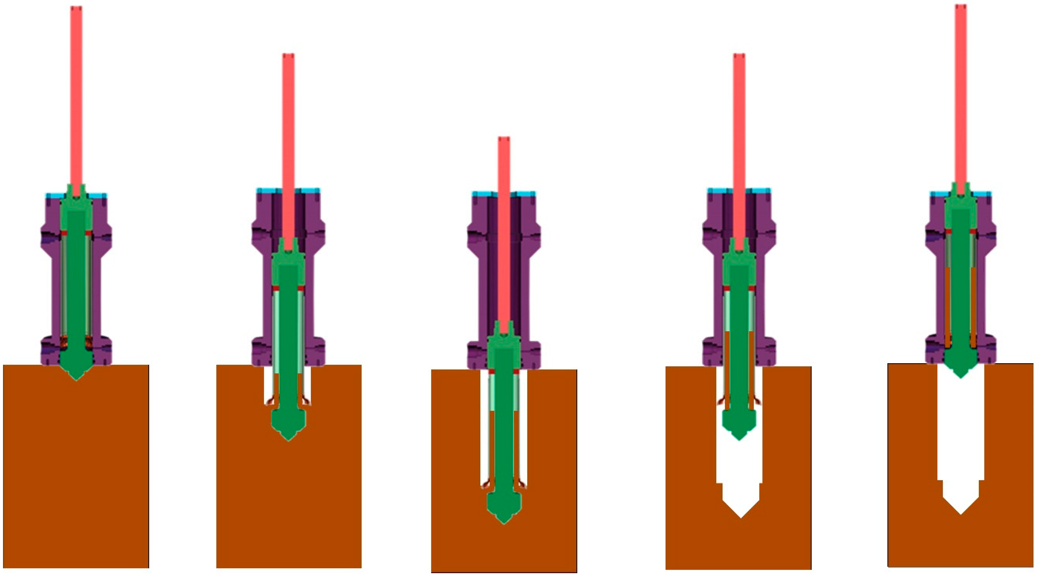
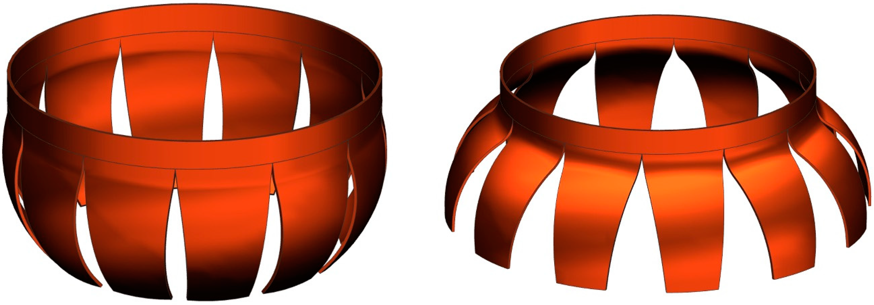
The sampling and sealing methods are different from the pressure sampler developed previously. The sampling device is installed on a hadal lander. The working principle of sediment sampling process is shown in Figure 2. When the sampling device reaches the bottom of the sea, the sampling cone that is used to reduce resistance of sampling process contacts the surface of the sediment firstly. The connecting rod is connected with the sampling cone and the piston, so that the lead screw, piston, sampling cylinder, etc. are connected into a whole by thread, and move synchronously. The oil-filled motor drives the sampling cylinder downward, and the core keeper opens after being free from the restriction of the pressure cylinder as shown in Figure 3. Because the opening diameter of the core keeper is greater than the diameter of the sampling cone, the sediment is squeezed into the sampling cylinder in the sampling process, and the sampling cylinder continues to move downwards until the bottom end surface of the piston is flush with the bottom end surface of the pressure cylinder, at the time, the maximum sediment sampling length can be obtained. After the sampling process is completed, the oil-filled motor reverses and the sampling cylinder is recovered into the pressure cylinder. During the recovery process, the core keeper is closed due to the compression by the inner wall of the pressure cylinder. The sediment left on the surface of the sampling cone is scraped off when passing through the dust ring at the lower end of the pressure cylinder, for a better sealing of bottom end surface by the cone. The upper end is sealed by the O-ring on the piston. After the sampling process, the sampler is lifted to the sea level, pressure loss may occur in the sampling cylinder due to leakage caused by the large pressure difference between inside and outside pressure, during which the accumulator compensates the internal pressure loss.
3. Simulation on Sampling Process
As shown by the model in Figure 4, during the sampling process, because of the large deformation of the sediment, it is difficult to predict the sampling length of the sediment in the sampling cylinder, the sampling length is affected by many factors. In the case of determining the whole structure, the effects of some factors, such as the installation position (the distance between the bottom end surface of the core keepers and the upper end surface of the sampling cone), L1, and the open diameter of the core keeper, D1, should be determined carefully and get more sediment. The sampling length increases with increasing L1, while the sediment may fall during recovering if L1 is too large. On the other hand, the sampling rate increases with D1, yet it becomes difficult during the recovery process if D1 is too large. In order to verify the feasibility of the sampling device and obtain the most reasonable installation position and open diameter of core keepers, the ABAQUS software was used to simulate and analyze the whole sampling process [16,17].
Considering the simulation operability, the model was simplified. The contact friction and pressure of sampling cylinder, core keepers, sampling cone and sediment are considered in the simulation. The Lagrangian method can accurately describe the movement trajectory of the particle, but when calculating the large deformation of the sediment, the excessive distortion of the mesh can easily lead to difficulty in convergence.
The Euler method overcomes the Lagrangian mesh distortion problem, but the material flow at the junction is difficult to calculate. Considering that the sampling process of the sampling cylinder penetrating the sediment will cause large deformation of the mesh in the simulation, the single Lagrangian method and the Euler method are not applicable, in order to avoid the problem of mesh distortion, the Coupled Eulerian-Lagrangian (CEL) method is adopted. The sampling cylinder is set in the Lagrangian form, and the sediment is set in Euler form. The model is shown in Figure 4. The total length of the sampling cylinder is L2, the diameter of the sampling cone is D2, the outer diameter of the sampling cylinder is 63 mm and the inner diameter is 60 mm, the diameter of the connecting rod is 36 mm, and the soil adopts an elastoplastic model with depth of L3 and diameter of D3. The parameters are shown in Table 1.
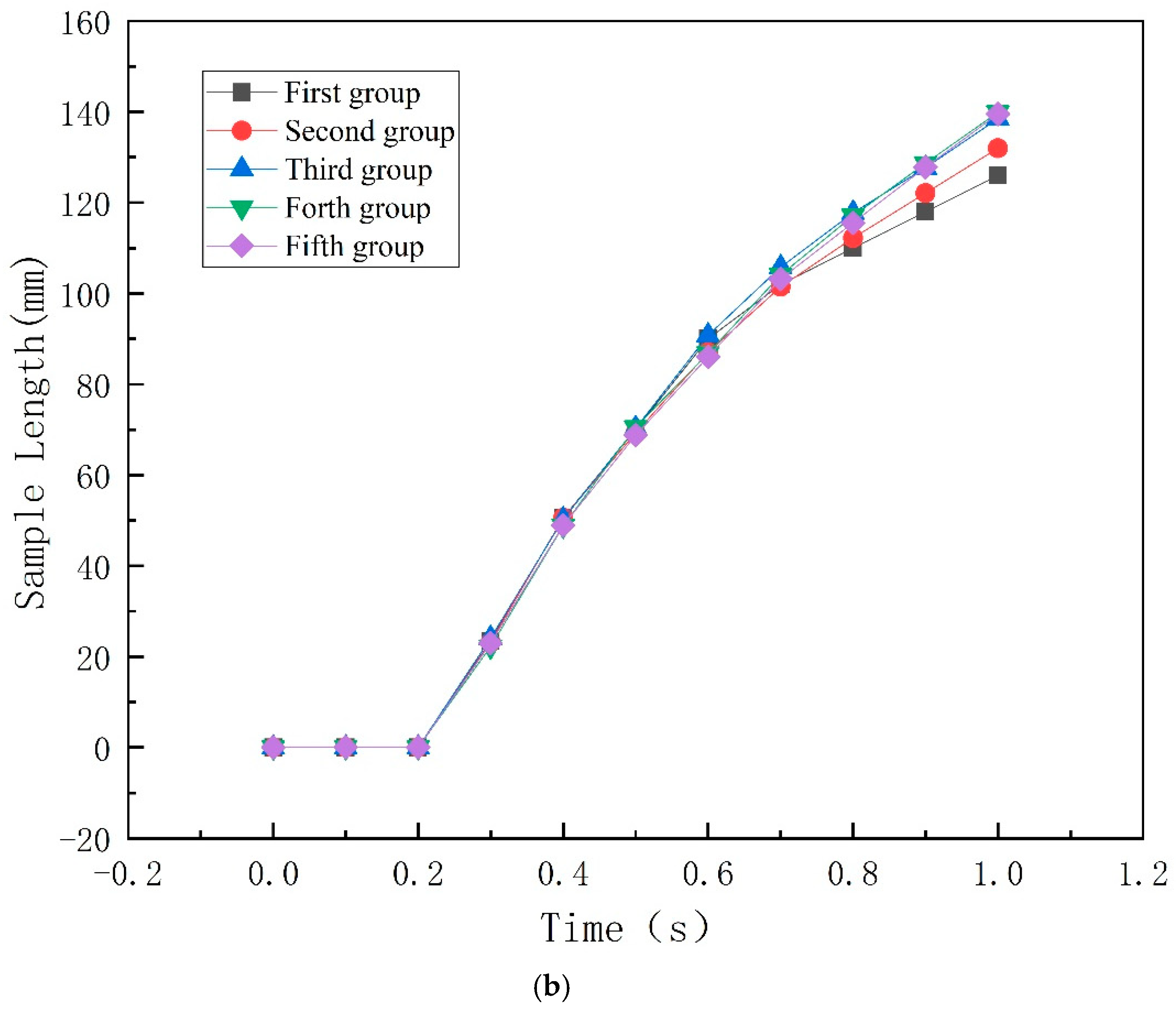
3.1. Mesh Test
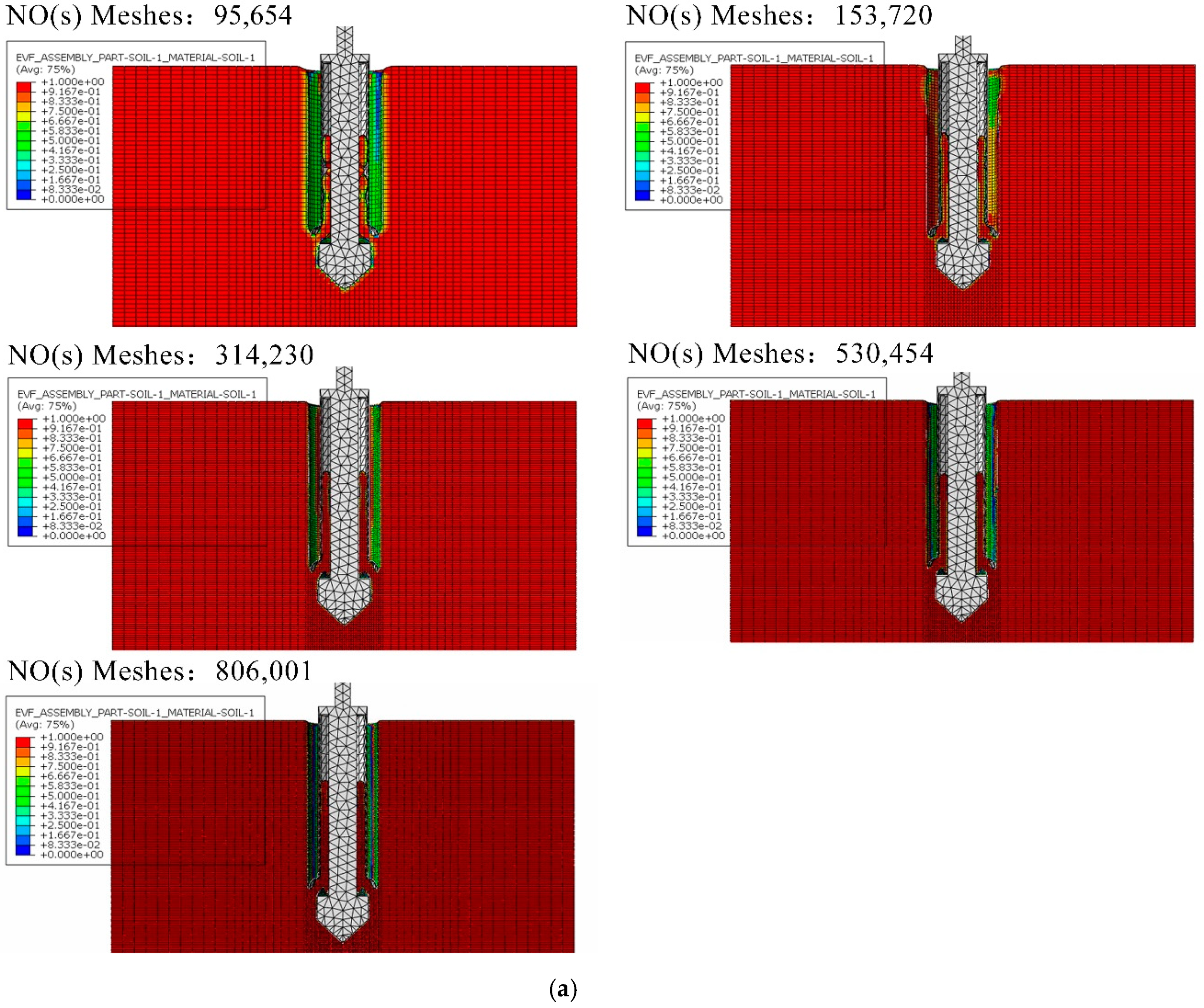
In the simulation, five mesh densities are adopt in the calculation, as shown in Table 2. The sampling length in the sampling cylinder referring is monitored. The simulation results at mesh test are shown in Figure 5a, the difference in the mesh number can be clearly seen through the shades of the color, and the sampling length is measuring by the software tool call “Query information, distance”. The legend shows the volume fraction of sediment, and it has little relationship with the sampling length that is measured by this simulation. The sampling length under different mesh numbers are shown in Figure 5b, it can be found that in the early stage of sampling process, due to the existence of the sampling cone, the sediment has not been able to enter the sampling cylinder, so the sampling length is 0. As time goes by, the sampling length gradually increases. From the mesh sensitivity investigation, it can be found that a mesh number of 314,230 is sufficient to capture the sampling process correctly. Therefore, in the following, the simulation is carried out using the mesh number close to Group 3.
3.2. Effect of the Installation Position of Core Keepers
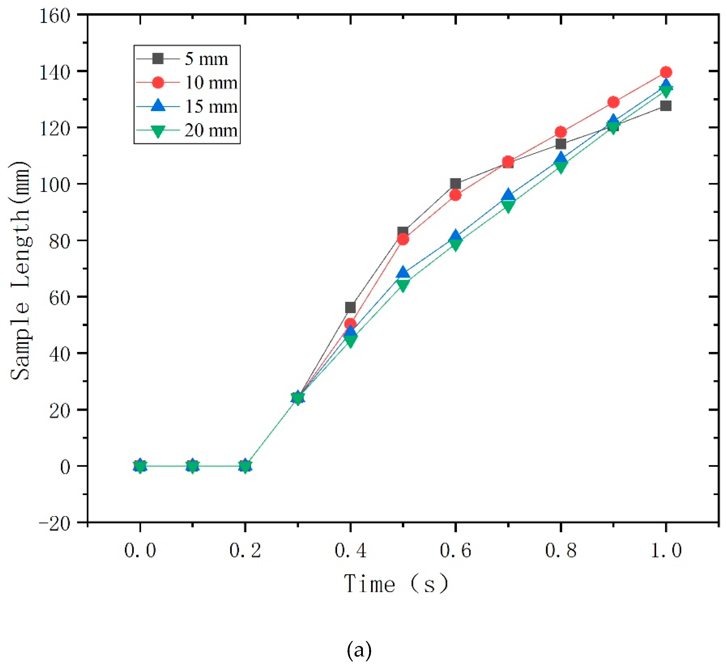
The installation position of the core keepers (the distance between the bottom end surface of the core keepers and the upper end surface of the sampling cone), L1, has a great influence on the sampling length of the sediment. By adjusting the installing position, the most suitable installation position of the sampling core keepers can be determined. The sampling result is shown in Figure 6a.
The value interval of the installation position is large, by further adjusting the value interval, a more suitable value of the installation position can be obtained, and the result obtained is shown in Figure 6b. Furthermore, as shown in Figure 6, a constant sampling rate can be found 0.6 s after the sampling process starts. Furthermore, the final sampling length is shown in Table 3. It can be found that the sampling length increases with increasing L1, at the beginning, and achieving a maximum value of 148.3 mm with L1 = 12 mm. The sampling length decreases with further increase of L1.
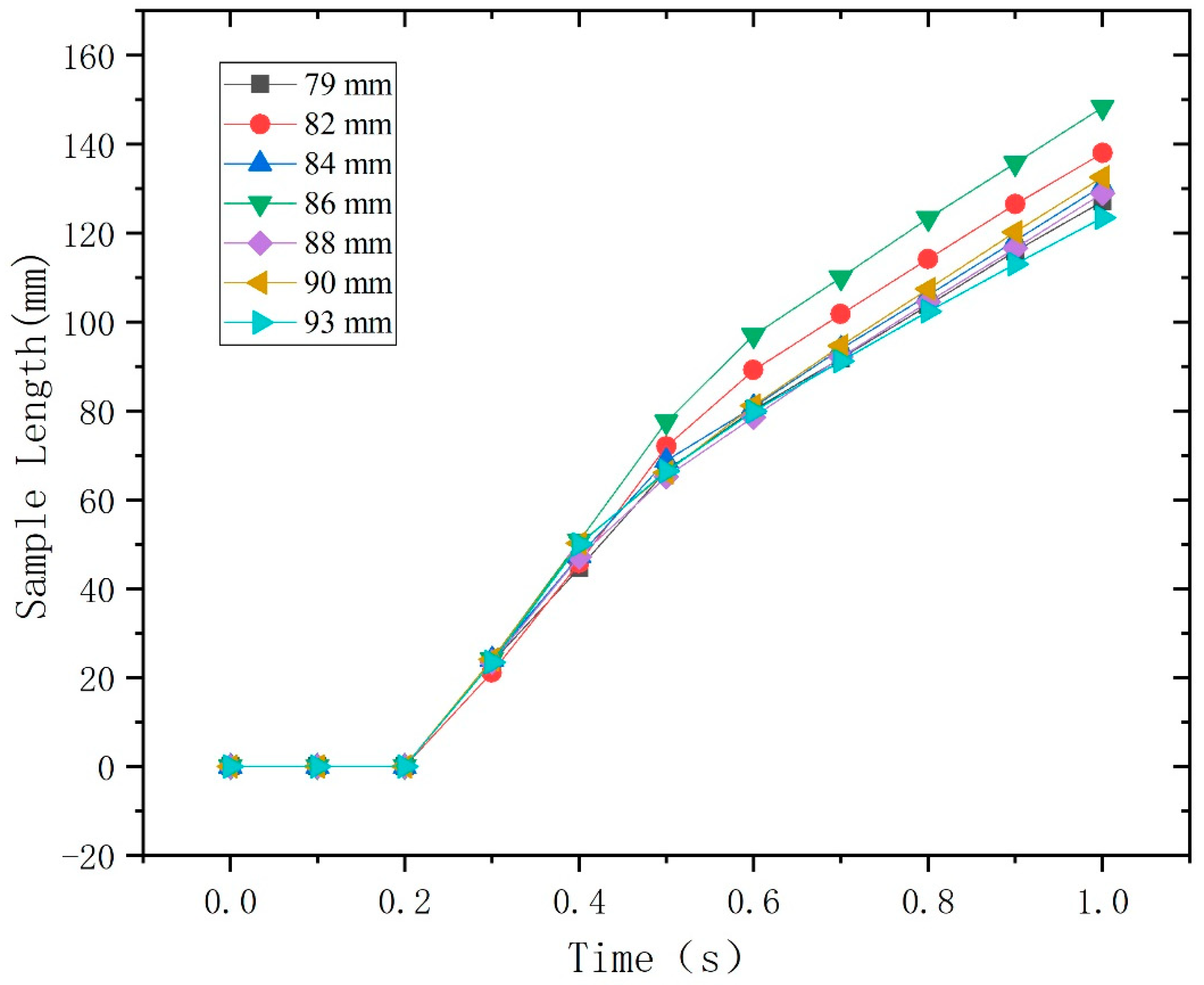
3.3. Effect of the Open Diameter of Core Keepers
The open diameter of the core keepers also influences the sampling length of the sediment. Based on the installation position of core keepers described above, by changing the open diameter of core keepers, the most suitable diameter D1 can be determined. The sampling results are shown in Figure 7, with the final sampling length shown in Table 4. The change of the sampling length with increasing D1 shows some fluctuation, yet a maximum sampling length can be observed at D1 = 86 mm, with the sampling length of 148.3 mm. The simulation result under the most suitable installation position and open diameter of core keepers is shown in Figure 8, and the red part in the sampling cylinder is the sediment length.
4. Experiment
In order to verify the feasibility of the sediment sampling device, a simple experiment is carried out. Here, the driving structure (motor, etc.) is not included in this experiment, and only the feasibility of the sampling structure is considered. As shown in Figure 9, the whole sampling structure is placed on the surface of the practical sediment and the sampling cylinder is pushed down manually to check the feasibility of the sampling process and the sampling length in the sampling cylinder. After the sampling process, the sampling cylinder is manually packed in the pressure cylinder to simulate the recovering of the sampling cylinder from the sediment, and the function of the stop plate is to increase the contact area with the surface of the sediment to ensure that it will not fall into the sediment due to the excessive weight of the device. The mud scraping effect of the dust ring is checked. The experiment is shown in Figure 10. It can be seen from the tests that the sampling device works well and the sampling process can be realized ideally.
5. Conclusions
In this paper, a new method of pressure-holding sampling for deep-sea sediments is presented, and the device has solved the sealing problem of the bottom end surface by changing the sampling form. In addition, the ABAQUS software is used to study the influence of the installation position and the open diameter of core keepers on the sediment sampling length. The conclusions are as follow:
- (1)
- A new pressure sampling device for sediments
The pressure-holding sampling device of deep-sea sediment provides a new sampling method that allow the sediment to be squeezed in from the core keepers on the side, using its own structure to achieve sealing, instead of relying on ball valves and plate valves for sealing, which greatly reduces the whole size and weight. In addition, the whole operation process is simple, with its own battery and control cabin, and independent of cable or ROV provided by the mother ship, which can be used in various environments. The feasibility of the device was verified through simulation.
- (2)
- The installation position of the core keepers
It can be seen from the results of simulation analysis that the installation position of the core keepers has a certain influence on the simulation results, under the condition that the length of the sampling cylinder is constant, the appropriate installation position can greatly increase the sampling length. When the installation position of the core keepers is 12 mm, the maximum sediment sampling length can be obtained, and the sampling length is 148.3 mm.
- (3)
- The open diameter of the core keepers
It can be seen from the results of simulation analysis that the open diameter of the core keepers has a certain influence on the simulation results, under the condition that the length of the sampling cylinder is constant, the appropriate open diameter can greatly increase the sampling length. When the open diameter of the core keepers is 86 mm, the maximum sediment sampling length can be obtained, and the sampling length is 148.3 mm.
Author Contributions
Conceptualization, Y.H., J.C. and Y.L.; methodology, J.C.; software, Y.H., J.C.; validation, Y.H., Y.F. and Y.W.; formal analysis, Y.H., J.C.; investigation, Y.L.; resources, P.Z., Y.F.; data curation, P.Z., X.L.; writing—original draft preparation, Y.H.; writing—review and editing, J.C.; visualization, Y.L., Y.W.; supervision, Y.L.; project administration, Y.H.; funding acquisition, J.C. All authors have read and agreed to the published version of the manuscript.
Funding
This research was funded by the National Key R&D Program of China, grant number SQ2018YFC030173.
Acknowledgments
The study is based on the project named “Research on frontier technology system of exploration, acquisition and exploitation of hadal biological resources”, which is derived from the National Key Research and Development Program of China (SQ2018YFC030173) supporting by the Ministry of Science and Technology of the People’s Republic of China.
Conflicts of Interest
The authors declare no conflict of interest.
References
- Yen, T.; Bu, J.; Li, S. Brief Study on the International Present Condition and Develop Tendency of the Technology of Sea Floor Sample Drilling. Geol. Sci. Technol. Inf. 2000, 19, 67–70. [Google Scholar]
- Li, F. Research on Undisturbed Pressure Sampling Technology of Deep-Sea Sediments; Zhejiang University: Hangzhou, China, 2008. [Google Scholar]
- Qin, H.; Chen, J.; Wang, J.; Kennedy, R.T.; German, I.; Thompson, J.E.; Witowjki, S.R. Design and experimental research of hydrostatic pressure-driven sampler. China Mech. Eng. 2013, 24, 942–945. [Google Scholar]
- Li, Y. Research on the Key Technology of Deep-Sea Sediment Sampler and Ball Valve; Zhejiang University: Hangzhou, China, 2016. [Google Scholar]
- Kvenvolden, K.A.; Barnard, L.A.; Cameron, D.H. Pressure Core Barrel: Application to the Study of Gas Hydrates, Deep Sea Drilling Project Site 533, Leg 76; Initial Reports DSDP: Washington, DC, USA, 1982; pp. 367–375. [Google Scholar]
- Dickens, G.R.; Paull, C.R.; Wallace, P. Direct measurement of in situ methane quantities in a large gas-hydrate reservoir. Nature 1997, 385, 426–428. [Google Scholar] [CrossRef] [Green Version]
- Storms, M.A. Ocean Drilling Program (ODP) deep sea coring techniques. Mar. Geophys. Res. 1990, 12, 109–130. [Google Scholar] [CrossRef]
- Schultheiss, P.J.; Francis, T.J.G.; Holland, M.; Roberts, J.A.; Amann, H.; Thjunjoto; Parkes, R.J.; Martin, D.; Rothfuss, M.; Tyunder, F.; et al. Pressure coring, logging and subsampling with the HYACINTH system. Geol. Soc. Lond. Spec. Publ. 2006, 267, 151–163. [Google Scholar] [CrossRef]
- Kawasaki, M.; Umezu, S.; Yasuda, M. Pressure Temperature Core Sampler (PTCS). J. Jpn. Assoc. Pet. Technol. 2006, 71, 139–147. [Google Scholar] [CrossRef] [Green Version]
- Inada, N.; Yamamoto, K. Data report: Hybrid Pressure Coring System tool review and summary of recovery result from gas-hydrate related coring in the Nankai Project. Mar. Pet. Geol. 2015, 66, 323–345. [Google Scholar] [CrossRef]
- Kubo, Y.; Mizuguchi, Y.; Inagaki, F.; Yamamoto, K.; Schultheiss, P.; Grigar, K.; Miller, J. A new hybrid pressure-coring system for the drilling vessel Chikyu. In Proceedings of the Integrated Ocean Drilling Program; EBSCO: Birmingham, AL, USA, 2014; Volume 17. [Google Scholar]
- Abegg, F.; Hohnberg, H.J.; Pape, T.; Bohrmann, G.; Freitag, J. Development and application of pressure-core-sampling systems for the investigation of gas- and gas-hydrate-bearing sediments. Deep Sea Res. Part I Oceanogr. Res. Pap. 2008, 55, 1590–1599. [Google Scholar] [CrossRef]
- Santamarina, J.C.; Dai, S.; Jang, J.; Terzariol, M. Pressure Core Characterization Tools for Hydrate-Bearing Sediments. Sci. Drill. 2012, 16, 44–48. [Google Scholar] [CrossRef]
- Chen, J.W.; Fan, W.; Bingham, B.; Chen, Y.; Gu, L.-Y.; Li, S.-L. A Long Gravity-Piston Corer Developed for Seafloor Gas Hydrate Coring Utilizing an In Situ Pressure-Retained Method. Energies 2013, 6, 3353–3372. [Google Scholar] [CrossRef] [Green Version]
- Luo, Y.; Peng, J.; Sun, M.; Sun, Q.; Ji, T.; Bo, K. An ice-valve-based pressure-coring system for sampling natural hydrate-bearing sediments: Proof-of-concept laboratory studies. J. Nat. Gas Sci. Eng. 2015, 27, 1462–1469. [Google Scholar] [CrossRef]
- Jian, X.U.; Guangyao, M. Analysis and Research on the Gravity Piston Corer Theory Based on ABAQUS. Hydromechatronics Eng. 2013, 41, 87–92. [Google Scholar]
- Sheng, Z.; Shi, Y.; Sun, J.; Qiu, R.; Lu, Y.; Liu, K.; Wang, X. Three-dimensional pile-soil settlement and deformation analysis under vertical load based on ABAQUS. Chin. J. Geotech. Eng. 2013, 35, 366–371. [Google Scholar]
Figure 1.
(a) The overall structure of the device; (b) The sampling structure part of the device.

Figure 2.
Schematic diagram of sediment sampling process.

Figure 3.
Schematic diagram of core keepers close (left) and open (right).

Figure 4.
Simulation analysis model diagram.

Figure 5.
(a) The simulation results at mesh test; (b) The sampling length under different mesh numbers.
Figure 5.
(a) The simulation results at mesh test; (b) The sampling length under different mesh numbers.


Figure 6.
(a) Sampling length under different installation positions; (b) The sampling length under further adjustment.
Figure 6.
(a) Sampling length under different installation positions; (b) The sampling length under further adjustment.


Figure 7.
Sampling length under different open diameters.

Figure 8.
The simulation result at sampling.

Figure 9.
Sampling process of sampling cylinder.

Figure 10.
Sampling process with pressure cylinder and dust ring.


Table 1.
Mesh test parameters.
| Parameter | Dimension (mm) |
|---|---|
| L2 | 235 |
| D2 | 66 |
| L3 | 1000 |
| D3 | 600 |
Table 2.
Simulation analysis results under different mesh numbers.
| Group | NO(s) Meshes | Length (mm) |
|---|---|---|
| 1 | 95,654 | 126 |
| 2 | 153,720 | 132 |
| 3 | 314,230 | 138.5 |
| 4 | 530,454 | 139.9 |
| 5 | 806,001 | 139.5 |
Table 3.
Simulation results under different installation positions.
| Distance (mm) | Length (mm) | Distance (mm) | Length (mm) |
|---|---|---|---|
| 5 | 127.6 | 12 | 148.3 |
| 6.5 | 132.4 | 13.5 | 142.5 |
| 8 | 143.2 | 15 | 134.8 |
| 10 | 139.5 | 20 | 133.1 |
Table 4.
Simulation results under different open diameters.
| Distance (mm) | Length (mm) | Distance (mm) | Length (mm) |
|---|---|---|---|
| 79 | 127.1 | 88 | 130 |
| 82 | 138 | 90 | 132.6 |
| 84 | 130.7 | 93 | 123.5 |
| 86 | 148.3 |
Publisher’s Note: MDPI stays neutral with regard to jurisdictional claims in published maps and institutional affiliations. |
© 2020 by the authors. Licensee MDPI, Basel, Switzerland. This article is an open access article distributed under the terms and conditions of the Creative Commons Attribution (CC BY) license (http://creativecommons.org/licenses/by/4.0/).
Share and Cite
MDPI and ACS Style
Chen, J.; Huang, Y.; Lin, Y.; Zhou, P.; Fang, Y.; Le, X.; Wang, Y. A Novel Sediment Pressure Sampling Device Carried by a Hadal-Rated Lander. J. Mar. Sci. Eng. 2020, 8, 839. https://doi.org/10.3390/jmse8110839
AMA Style
Chen J, Huang Y, Lin Y, Zhou P, Fang Y, Le X, Wang Y. A Novel Sediment Pressure Sampling Device Carried by a Hadal-Rated Lander. Journal of Marine Science and Engineering. 2020; 8(11):839. https://doi.org/10.3390/jmse8110839
Chicago/Turabian StyleChen, Jiawang, Yue Huang, Yuan Lin, Peng Zhou, Yuping Fang, Xiaoling Le, and Yuhong Wang. 2020. "A Novel Sediment Pressure Sampling Device Carried by a Hadal-Rated Lander" Journal of Marine Science and Engineering 8, no. 11: 839. https://doi.org/10.3390/jmse8110839
Note that from the first issue of 2016, this journal uses article numbers instead of page numbers. See further details here.