Improving Low Frequency Isolation Performance of Optical Platforms Using Electromagnetic Active-Negative-Stiffness Method

1
Center of Ultra-Precision Optoelectronic Instrument Engineering, Harbin Institute of Technology, Harbin 150080, China
2
Key Lab of Ultra-Precision Intelligent Instrumentation (Harbin Institute of Technology), Ministry of Industry and Information Technology, Harbin 150080, China
3
Shanghai Marine Equipment Research Institute, Shanghai 200031, China
*
Author to whom correspondence should be addressed.
Appl. Sci. 2020, 10(20), 7342; https://doi.org/10.3390/app10207342
Submission received: 8 September 2020
/
Revised: 7 October 2020
/
Accepted: 12 October 2020
/
Published: 20 October 2020
Abstract
:To improve the low-frequency isolation performance of optical platforms, an electromagnetic active-negative-stiffness generator (EANSG) was proposed, using nano-resolution laser interferometry sensors to monitor the micro-vibration of an optical platform, and precision electromagnetic actuators integrated with a relative displacement feedback strategy to counteract the positive stiffness of pneumatic springs within a micro-vibration stroke, thereby producing high-static-low-dynamic stiffness characteristics. The effectiveness of the method was verified by both theoretical and experimental analyses. The experimental results show that the vertical natural frequency of the optical platform was reduced from 2.00 to 1.37 Hz, the root mean square of displacement was reduced from 1.28 to 0.69 μm, and the root mean square of velocity was reduced from 14.60 to 9.33 μm/s, proving that the proposed method can effectively enhance the low frequency isolation performance of optical platforms.
1. Introduction
According to the linear vibration theory, the isolation of micro-vibration can only be achieved when the excitation frequency is greater than wn, where wn is the natural frequency of a vibration isolator. The vibration isolation bandwidth of a vibration isolator increases when its natural frequency decreases. The natural frequency of a vibration isolator can be reduced by either increasing its mass of payload or decreasing its stiffness. However, it is usually necessary to increase the stiffness of the isolator to maintain its stability when the mass of the payload increases. Negative-stiffness vibration isolators are isolators that use various kinds of restoring force, whether passive [1,2,3,4,5,6,7,8,9,10,11,12,13,14,15,16,17,18,19,20,21], semi-active [22,23,24,25,26,27,28], or active [29,30], to produce negative-stiffness characteristics, thus partially counteracting the positive stiffness within a micro-vibration stroke. And they have shown effective to produce high-static-low-dynamic stiffness characteristics.
Much work has been performed on passive negative stiffness vibration isolators and their application has been summarized by Ibrahim [1]. For example, pre-stressed bars or beams [2,3], inclined springs with axial preload [4,5,6], cam-roller-spring mechanisms [7,8], and scissor-like structures [9] combined with a vertical spring in parallel, can produce high-static-low-dynamic stiffness. In addition, cubic permanent magnets in attractive [10,11], repulsive [12,13], or a combination of attractive and repulsive configuration [14,15], permanent magnet rings magnetized axially [16,17] or radially [18,19] were well proposed to produce negative stiffness with non-contact characteristics. The negative stiffness of the above vibration isolators was not easy to adjust, so their optimal performance can only be achieved when they are with a certain payload and geometric parameters. In addition, these vibration isolators only show advantages for small- and micro-vibration, and the resonance peak was noticeably large and its inherent cubic nonlinearity may lead to bifurcation and a chaotic response for vibration with large amplitude [20,21]. Semi-active negative stiffness vibration isolators were proposed to realize the variable stiffness characteristic and to cope with the variation of excitation frequency or system parameters. Palomares [22] used linear pneumatic actuators instead of inclined springs to obtain adjustable negative stiffness, and the natural frequency was reduced by up to 58%. Christopher [23] proposed a fast and effective dynamically tunable stiffness structure using piezoelectric actuators. Zhou [24] proposed a tunable negative-stiffness spring composed of a pair of electromagnets and a permanent magnet. Han [25] used an electromagnetic asymmetric tooth structure to obtain variable negative stiffness, which can be adjusted through tuning the magnitude of input current. Pu [26] proposed an electromagnetic negative stiffness vibration isolator composed of multilayer magnets and coils. Sun [27] presented an electromagnetic negative stiffness spring containing with two coaxial annular electromagnets, whose negative stiffness was adjusted by changing the current in rectangular cross-section coils. Wang [28] realized the stiffness adjustment by introducing a regulation mechanism into a negative stiffness structure composed of a pair of coaxially magnetized coaxial magnetic rings. The semi-active negative stiffness isolator was an open-loop control system, which had low control accuracy and cannot compensate the deviation caused by external interference. Active negative stiffness vibration isolators with high control accuracy also show advantages in generating variable stiffness characteristics and better low-frequency vibration isolation performance. For example, Zhang [29] proposed a magnetic negative stiffness vibration isolator based on Maxwell normal stress and integrated acceleration feedback to deal with various conditions, which has characteristics of fast response, no mechanical friction, and compactness. Compared with passive isolation, the natural frequency was reduced by 80%. However, active negative stiffness vibration isolators have not been widely used in vibration isolation systems. The reason was that high-precision sensors [30] and linear actuators [31] are required to monitor and counteract the low-frequency micro-amplitude vibration of the payload, leading to high costs and system complexity [27]. Moreover, poor resolution and a dynamic range of commercial inertial sensors at low-frequency also limit the application of the active negative stiffness vibration isolators in vibration isolation systems [30].
In this paper, a novel electromagnetic active-negative stiffness generator (EANSG) is proposed, which uses nano-resolution laser interference sensors to monitor the micro-vibration of an optical platform, and precision electromagnetic actuators integrated with a relative displacement feedback algorithm to counteract the positive stiffness of pneumatic springs. This paper is organized as follows. In Section 2, the principle of the proposed EANSG was presented. In Section 3, the design and realization of EANSG was described including the designs of nano-resolution laser interferometry sensors, electromagnetic actuators, and relative displacement feedback strategy. In Section 4, an experimental setup was established to validate the effectiveness of the proposed method, and the experimental results were analyzed. Conclusions are drawn in Section 5.
2. Principle
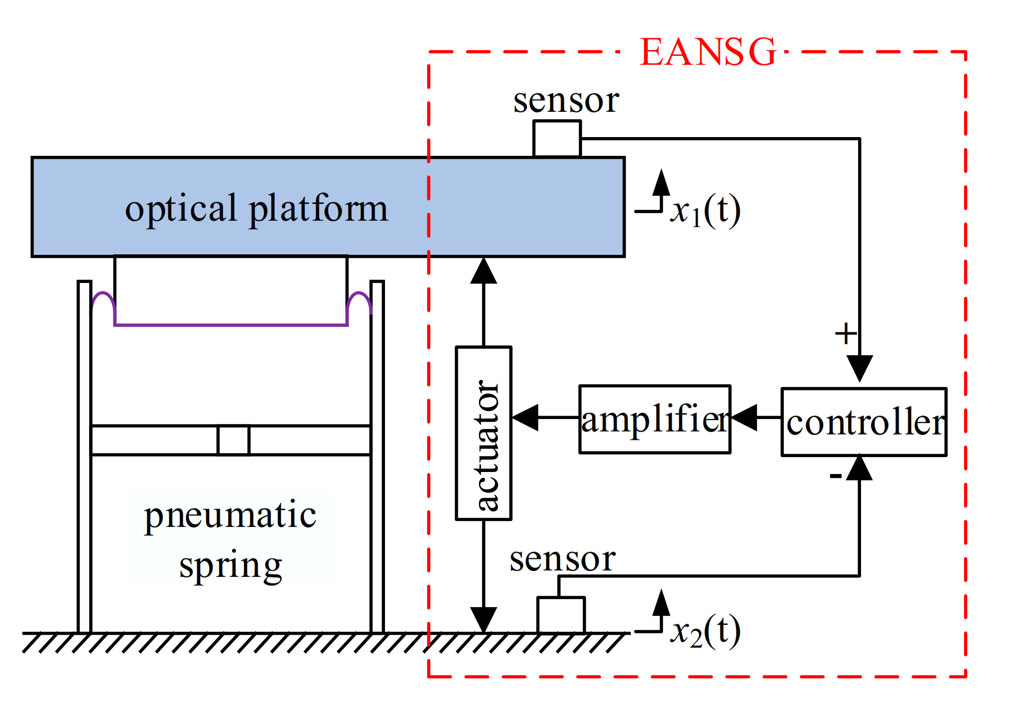
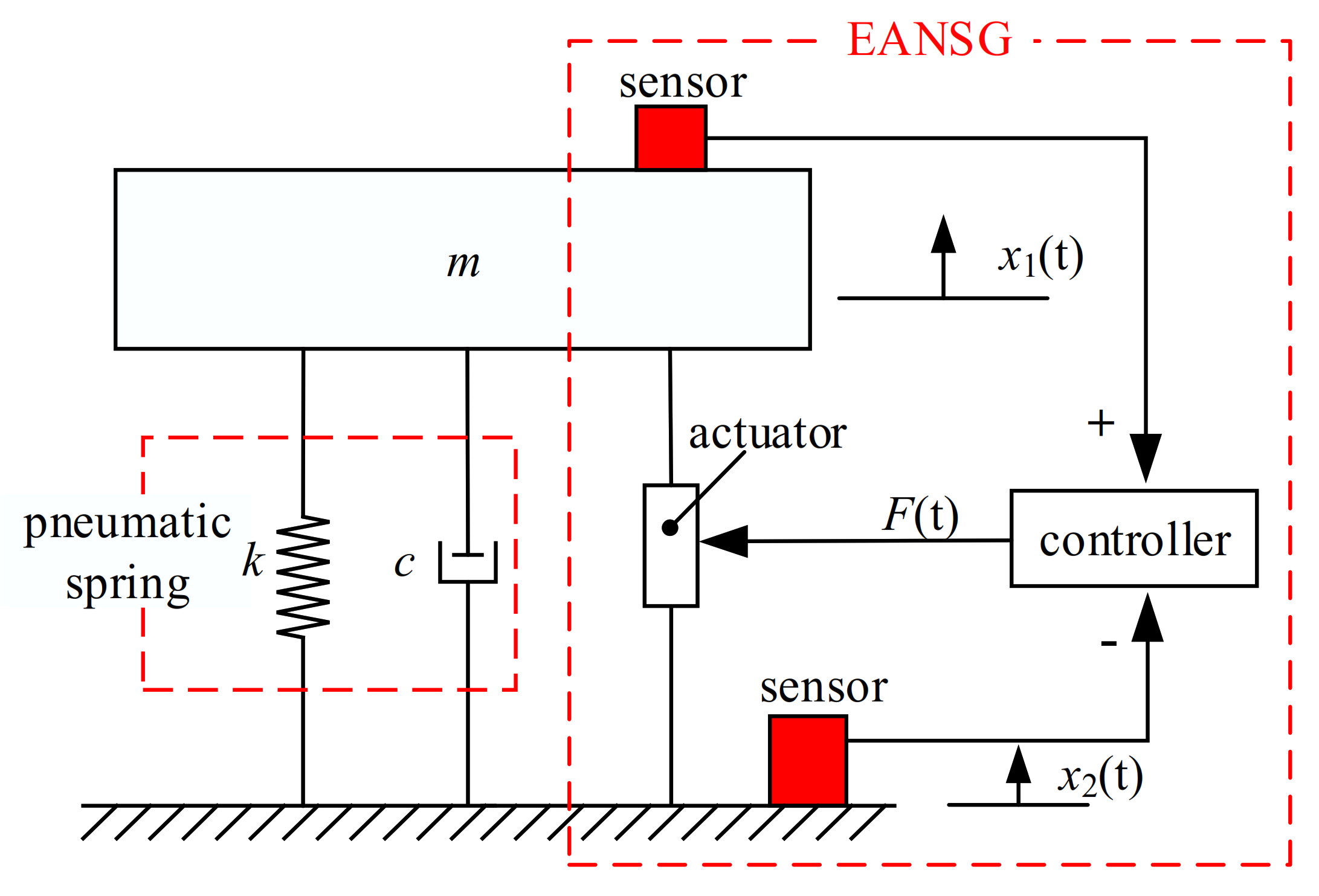
Due to the limitations of material property and fabrication technology, the vertical natural frequency of an optical platform supported by pneumatic springs, which is shown in Figure 1, is usually higher than 2 Hz. To generate low and ultra-low frequency isolation characteristics, EANSG was used to counteract the partial positive stiffness of each pneumatic spring. It mainly involves feedback sensors, a controller, an amplifier, and an actuator. A nano-resolution laser interferometry sensor was developed to monitor the micro-vibration of the optical platform relative to the ground, i.e., x1(t)–x2(t), and serve as a feedback sensor. The controller and the amplifier were used to output a driving current into the electromagnetic actuator according to the feedback signal of the laser interferometry sensor and the control strategy. The electromagnetic actuator with high linearity was used to counteract the positive stiffness of the pneumatic spring by actively producing negative stiffness within a micro-vibration stroke. The pneumatic spring together with the paralleled EANSG form a low frequency performance enhanced isolator (LFPEI).
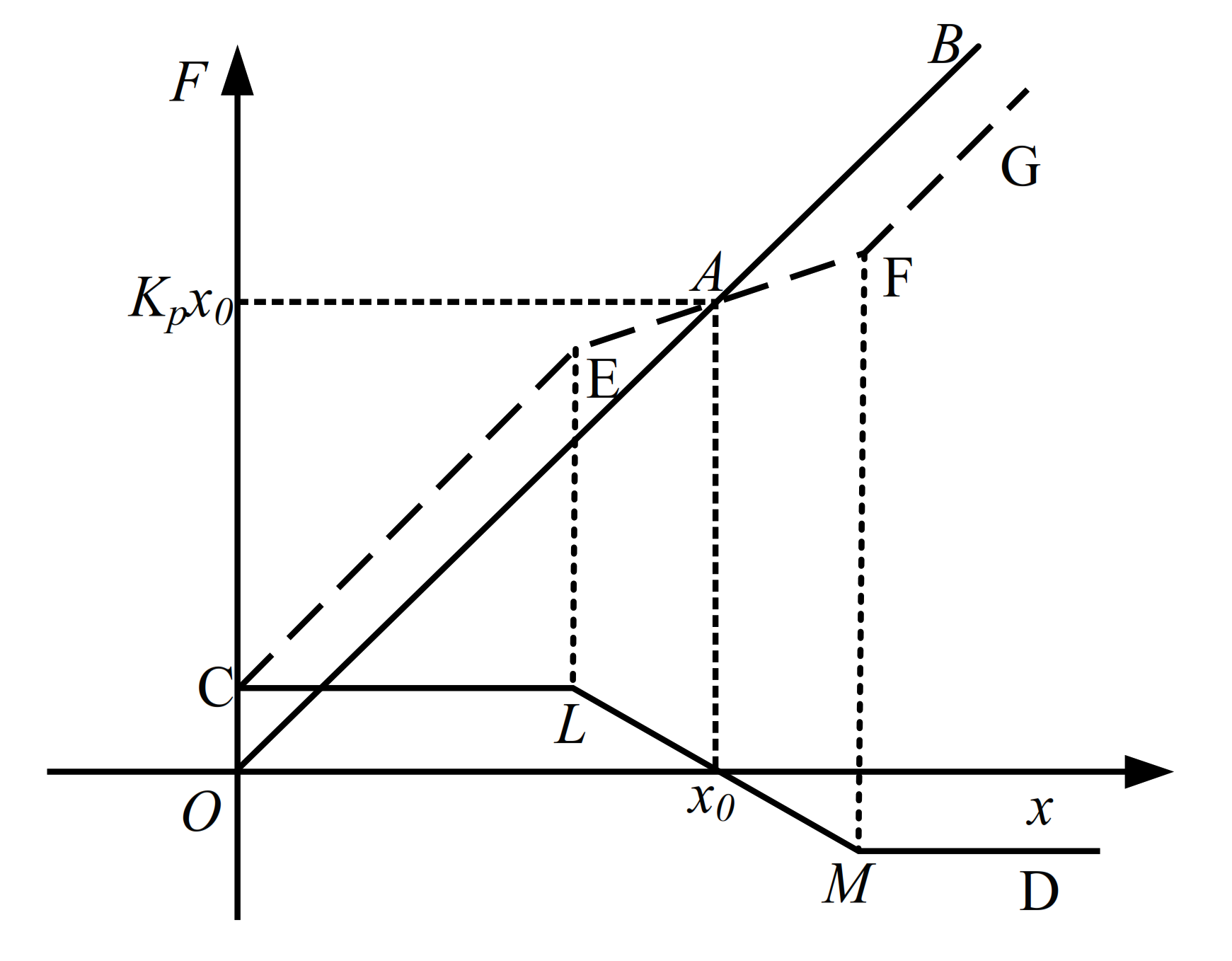
The displacement response of an optical platform to environmental random excitations is generally as small as ±10 μm, and the force–displacement characteristics of a pneumatic spring within this range can be considered as linear. The principle of EANSG was illustrated in Figure 2. Solid lines OB, CLMD, and dotted-line CEFG are force–displacement curves of the pneumatic spring, EANSG, and LFPEI. Slopes of the above three curves Kp, Kn, and K represent their stiffness, respectively. x0 is the static equilibrium position of the pneumatic spring and LM is the effective stroke of the electromagnetic actuator. At point x0, the force exerted by the EANSG is zero, i.e., the optical platform and payload are supported by the pneumatic spring. In the range of LM, the optical platform and payload are supported by the pneumatic spring and EANSG, and the stiffness of LFPEI equals to the sum of Kp and Kn. Beyond that range of LM, the force exerted by EANSG is constant, and K is equal to Kp. Adjusting Kn can make K close to but a little greater than zero in the range of LM, i.e., the adoption of EANSG makes the pneumatic spring have lower local dynamic stiffness to isolate low and ultra-low frequency micro-vibrations without sacrificing its payload capability. Therefore, it can be concluded that the proposed method can produce high-static-low-dynamic stiffness and resolve the conflict between the high payload and low stiffness of an optical platform.
3. Design and Realization
3.1. Nano-Resolution Laser Interferometry Sensor
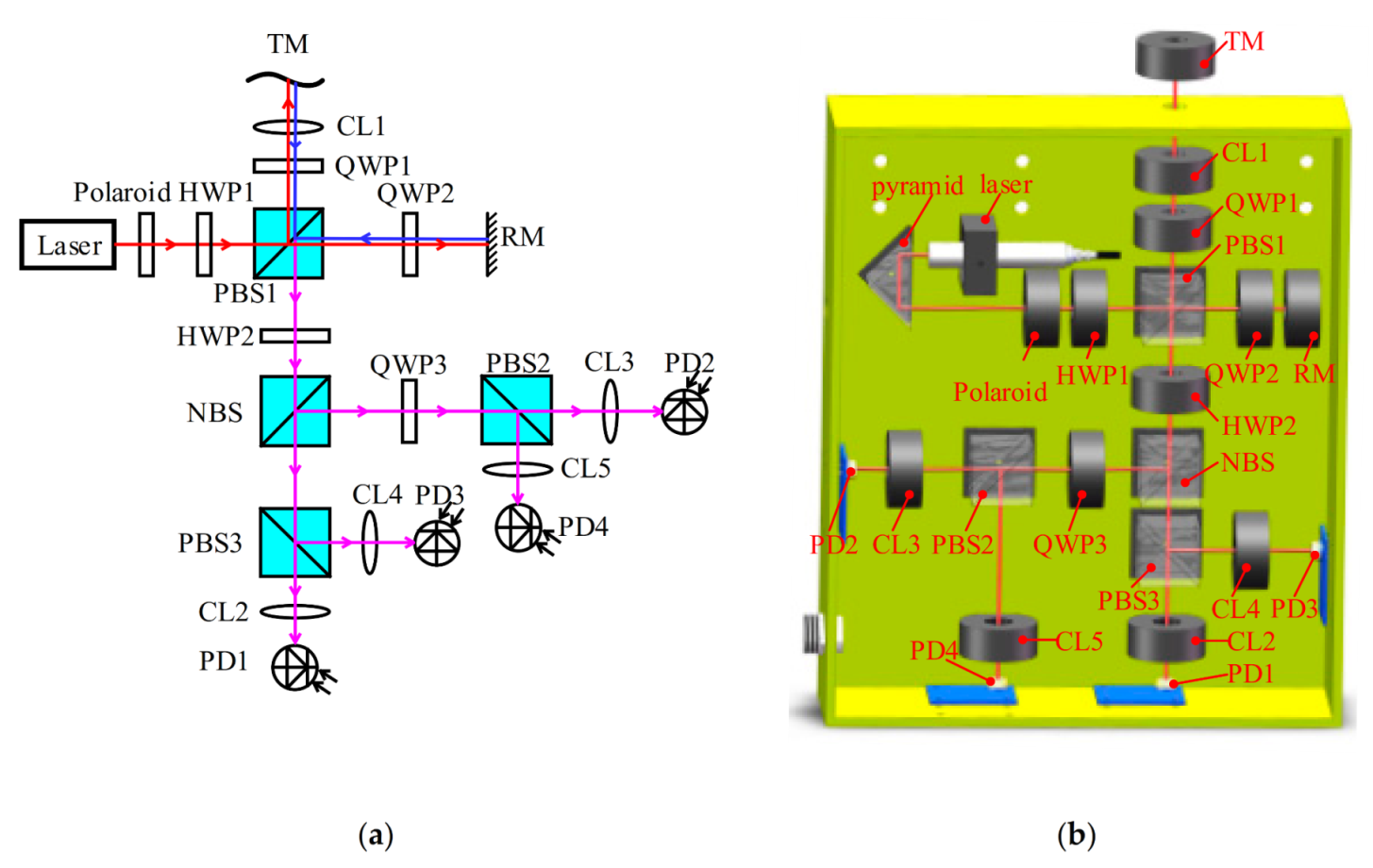
The amplitude of the micro-vibration of an optical platform under environmental random excitation is usually as small as micron scale, so a nano-resolution displacement sensor was needed to monitor and feedback such micro-vibration accurately. The scheme and design of the proposed nano-resolution laser interferometry sensor are shown in Figure 3. A single-frequency circularized beam is output by a collimated laser diode with a wavelength of 635 nm, and it turns into a linear polarized beam through a polaroid. The linear polarized laser beam passes through the first half-wave plate (HWP1) and is split into one reference beam and one measurement beam by the first polarizing beam splitter (PBS1). The reference beam passes through the second quarter-wave plate (QWP2), and then is reflected by a reference mirror (RM) to the PBS1. The measurement beam passes through the first quarter-wave plate (QWP1), and then is reflected by a target mirror (TM) to the PBS1. The reflected reference beam and transmitted measured beam recombine and are incident into the second half-wave plate (HWP2), the recombined incident beam is then evenly split into two beams by a non-polarizing beam splitter (NBS), and the nominal split ratio of the NBS is 50%:50%. One beam passes through the third quarter-wave plate (QWP3) and is split into two beams by the second polarizing beam splitter (PBS2), the other beam is also split into two beams by the third polarizing beam splitter (PBS3). Four photodiodes (PD), named PD1, PD2, PD3, and PD4, are used to detect four interference signals with phases of 0°, 90°, 180°, and 270°, respectively. Convex lenses (CL) before PDs and TM are used to gather beams. The intensity of laser beams detected by four PDs can be expressed as
where is the phase introduced by ΔL, ΔL is the displacement of the TM, λ is the wavelength of laser diode, n is the channel number and equals 1 to 4. An and Bn are the DC bias and AC amplitude of laser intensity.
According to Equation (1), it can be obtained:
where A1 − A3 = A2 − A4 = 0, B1 + B3 = B2 + B4. Equation (2) is a circle function with a radius of (B1 + B3) and center at (0, 0).
The displacement of the TM is:
where ϕ = arctan Iy/Ix.
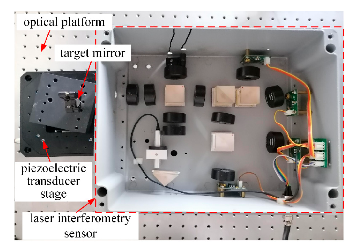
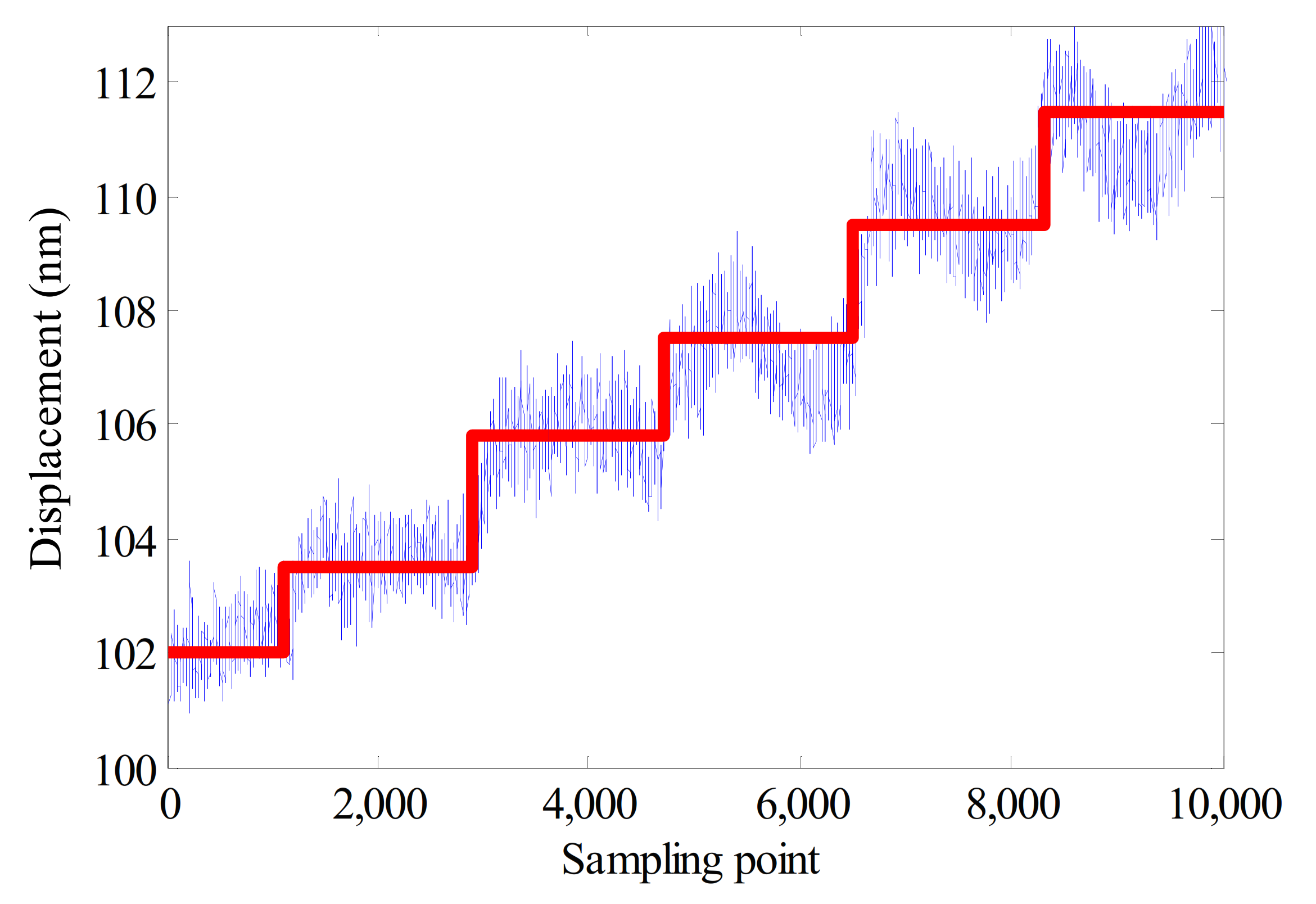
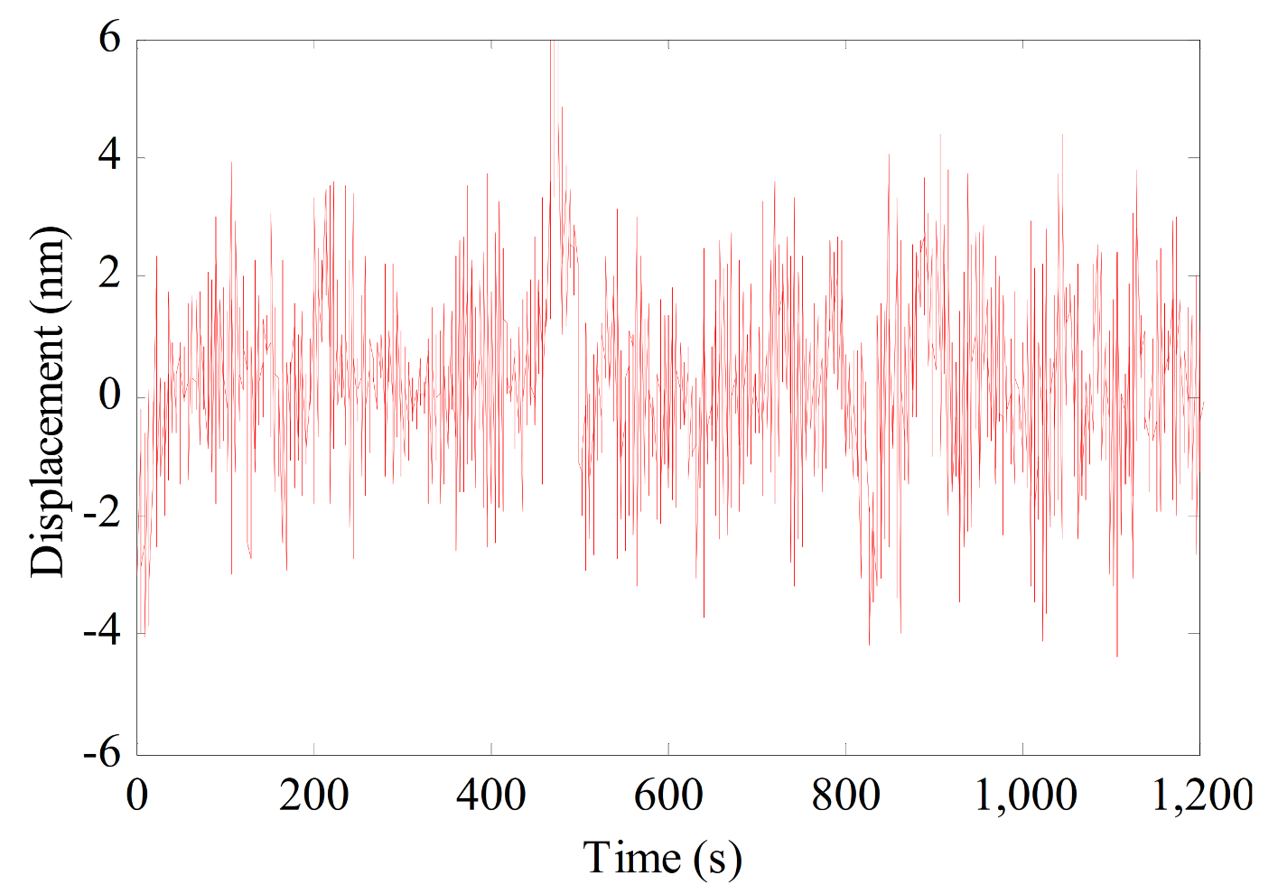
As shown in Figure 4, a prototype of the laser interferometry sensor was developed, and an experimental setup was set on an optical platform to test its resolution and stability. In the resolution experiment, the laser interferometry sensor was kept still, while the TM is driven away from the sensor with a constant step by a nano-resolution piezoelectric transducer (PZT) stage. The smallest step that causes a perceptible change in the measured displacement is defined as the resolution of the laser interferometry sensor. Experimental results in Figure 5 show that its resolution is better than 2 nm. In the stability experiment, the TM is kept still, and signals of PD1 to PD4 are measured simultaneously and then analyzed. As shown in Figure 6, the stability of the laser interferometry sensor is better than ±6 nm/20 min. It can be seen from Figure 5 and Figure 6 that the proposed laser interferometry sensor can achieve the nano-resolution and low sensitivity to environmental noise, which meets our requirements for micron amplitude environmental vibration monitoring and feedback. The maximum sampling rate of the developed nano-resolution laser interferometry sensor was set to 1 kHz, which is sufficient to measure the environmental micro-vibration interference with a frequency mostly less than 50 Hz.
3.2. Electromagnetic Actuator
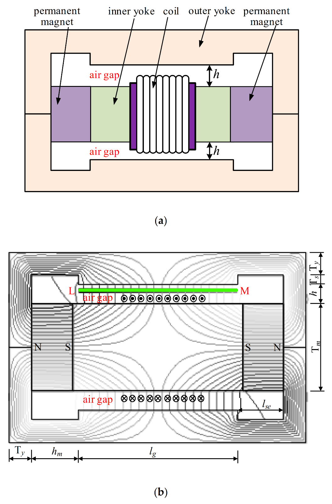
To precisely generate negative stiffness within the micro-vibration range of an optical platform, an electromagnetic actuator with high linearity and high precision was proposed, as shown in Figure 7. A pair of cubic permanent magnets in a repulsive configuration was used to produce uniform magnetic flux density in the air gap. Two outer yokes and one inner yoke were symmetrically placed around the permanent magnets to form a closed double magnetic circuit. The cubic permanent magnet is made of NdFe35, the material of outer yokes and inner yoke are DT4C. A coil was located in the air gap and moves along the inner yoke, the magnetic force applied on the coil can be expressed as
where n and l are the turns and length of the coil, B is the magnetic flux density in the air gap, I is the driven current; F is the magnetic force, and its direction is perpendicular to I and B.
The nonlinearity of the electromagnetic actuator was defined as the non-uniformity of the magnetic flux density in the air gap, which is expressed as
where is the average magnetic flux density along the air gap, B(x) is the magnetic flux density along the air gap, and Llm is the length of the air gap.
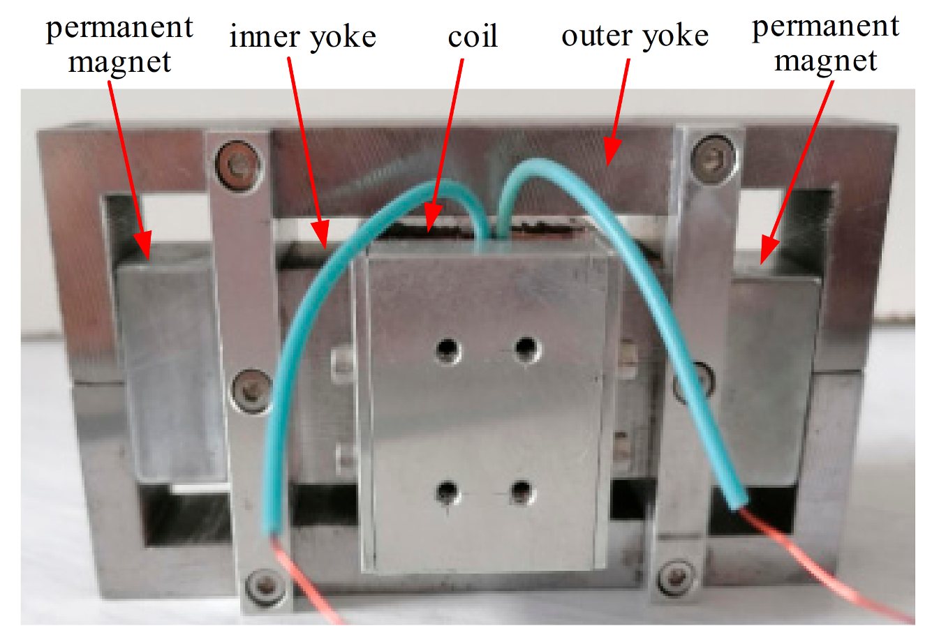
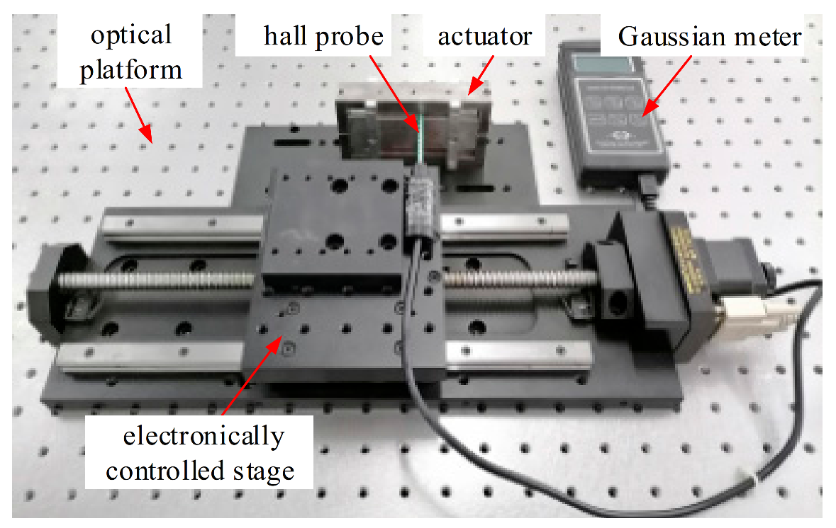
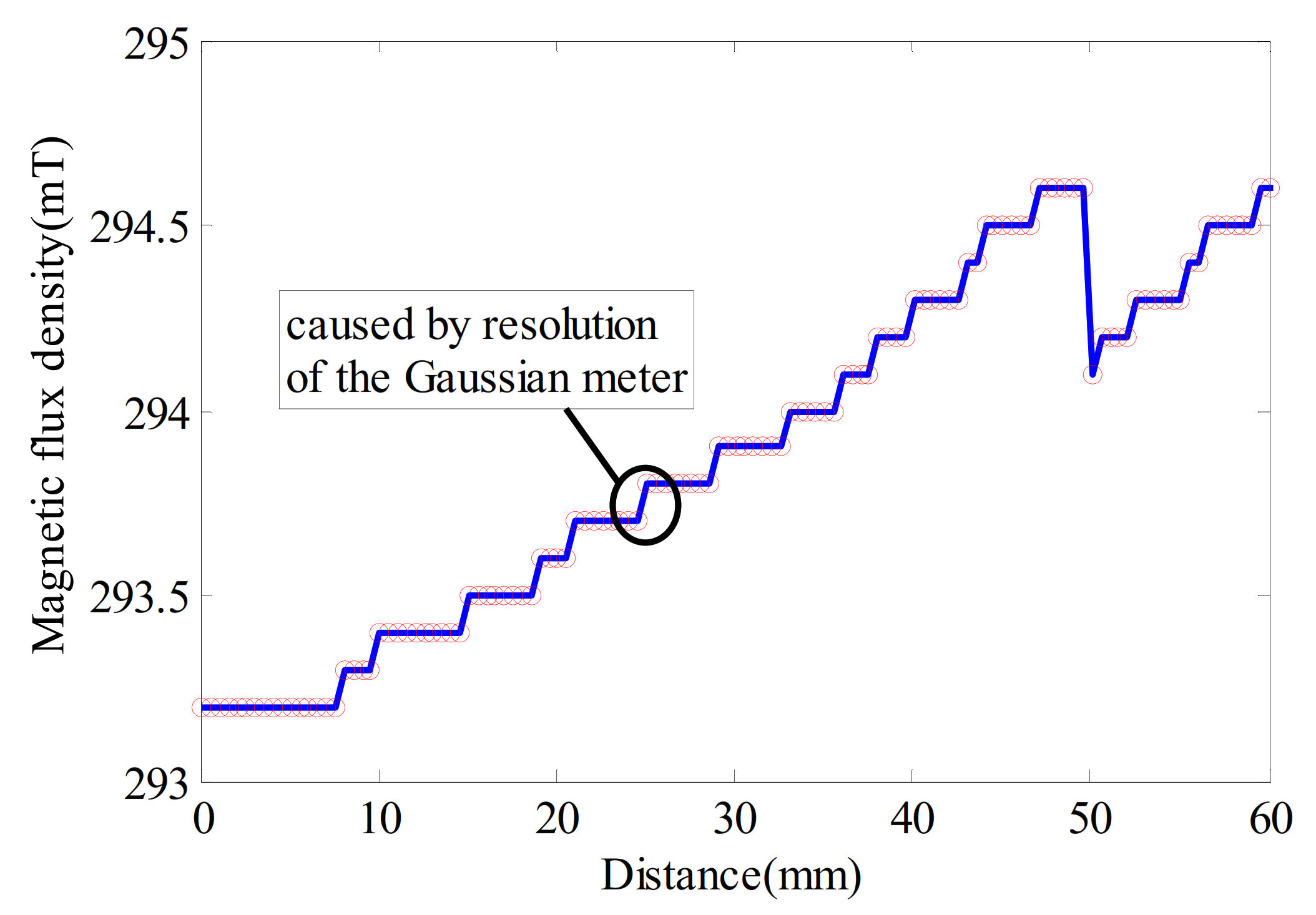
As shown in Figure 8, an electromagnetic actuator with geometric parameters listed in Table 1 was developed. The uniformity of the magnetic flux density in the air gap is a key index that influences the force linearity of the electromagnetic actuator, so an experimental setup shown in Figure 9 was set on an optical platform to measure the magnetic flux density. The electromagnetic actuator was placed in parallel with an electronically controlled stage, and the stage was driven by a stepper motor to generate a standard step of 0.5 mm. One end of a Gaussian meter hall probe with a resolution of 0.1 mT was fixed with the stage, while the other was inserted into the air gap of the electromagnetic actuator. Experimental results in Figure 10 show that along the 60 mm stroke of the electromagnetic actuator, the maximum and minimum magnetic flux densities are 294.6 mT and 293.2 mT, respectively, and the nonlinearity of magnetic flux density calculated by Equation (6) is less than 0.48%. The small jump in the magnetic flux density curve was due to the resolution of the Gaussian meter.
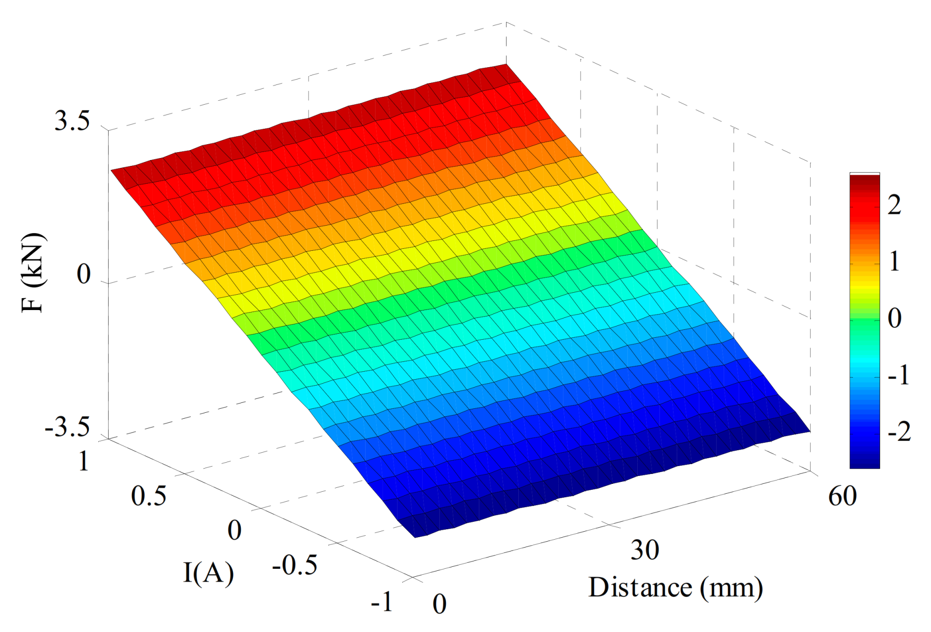
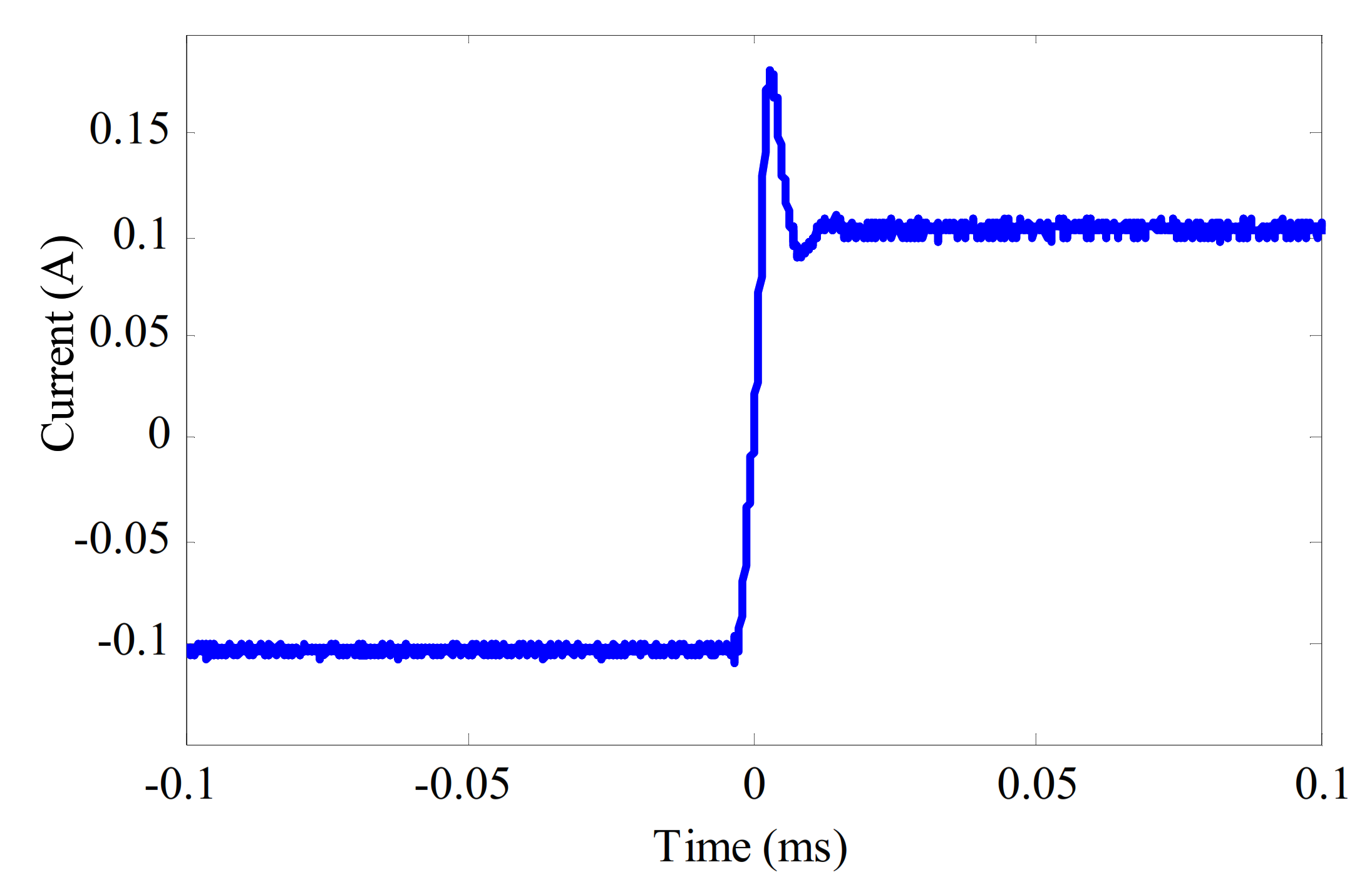
The magnetic force–drive current curved surface in Figure 11 well shows the static characteristics of the electromagnetic actuator. The electromagnetic active-negative-stiffness method uses the magnetic force of the electromagnetic to realize feedback control. The magnetic force was generated instantaneously, so its dynamic performance mainly depends on the dynamic performance of an amplifier. It can be seen from the step response curve in Figure 12, the rise time of the amplifier is less than 10 μs, and the settling time is less than 20 μs. The bandwidth test curve in Figure 13 shows that there is no distortion and attenuation to the sweep signal from 1 to 5 kHz, which indicates that the bandwidth of the amplifier is higher than 5 kHz.
In this paper, the servo frequency of the electromagnetic active-negative-stiffness generator is set to 300 Hz, which is far lower than the bandwidth of an electromagnetic actuator, higher than the bandwidth of the environmental micro-vibration interference with a frequency mostly less than 50 Hz.
3.3. Relative Displacement Feedback Strategy
As shown in Figure 14, a relative displacement feedback strategy was adopted to generate negative stiffness. The driven current of the electromagnetic actuator was set proportionally to the displacement of the optical platform relative to the ground, which can be expressed as
where ki is the current feedback coefficient, x1(t) is the absolute displacement of the optical platform, and x2(t) is the absolute displacement of the ground.
In this research, the displacement of the optical platform relative to the ground, i.e., x1(t)–x2(t), was measured by the proposed laser interferometry sensor. According to Equations (5) and (7), the dynamic equation of LFPEI, which is composed of the pneumatic spring and paralleled EANSG, is given by
where m is the mass of the payload, c and k are the damping and stiffness of the pneumatic spring. F(t) is the force exerted by the electromagnetic actuator on the payload, ks = NBLki.
After the Fourier transform and dimensionless processing, the displacement transmissibility of LFPEI can be expressed as
where α = ks/k is the feedback coefficient, wn = is the natural frequency of the pneumatic spring, ξ = c/2mwn is the damping ratio, and β = w/wn is the frequency ratio.
According to Equation (9), the natural frequency wn’, damped natural frequency w, and resonance peak Tmax of LFPEI, respectively, can be expressed as
Due to the low damping of pneumatic springs, its damped natural frequency w was usually taken as the natural frequency wn’. Equation (10) shows that a positive α makes the natural frequency wn’ of LFPEI lower than that of a pneumatic spring, which results from the negative stiffness characteristics generated by the relative displacement feedback strategy. Moreover the closer the feedback coefficient α is to 1, the lower the natural frequency wn’ will be. To prevent the stiffness of LFPEI from being negative, which would result in instability, the range of the feedback coefficient α was limited to (0, 1). Therefore, in this paper, α = 0.5 was adopted to validate the effectiveness of the proposed method. The theoretical natural frequency of LFPEI wn’ is 71% of that of the pneumatic spring wn.
The expression of resonance peak Tmax in Equation (12) indicates that it is affected by the feedback coefficient α in the same way as the natural frequency. Therefore, it can be concluded that the proposed method can enhance the low-frequency vibration isolation performance and simultaneously suppress the resonance peak of a pneumatic spring through adopting a relative displacement feedback strategy.
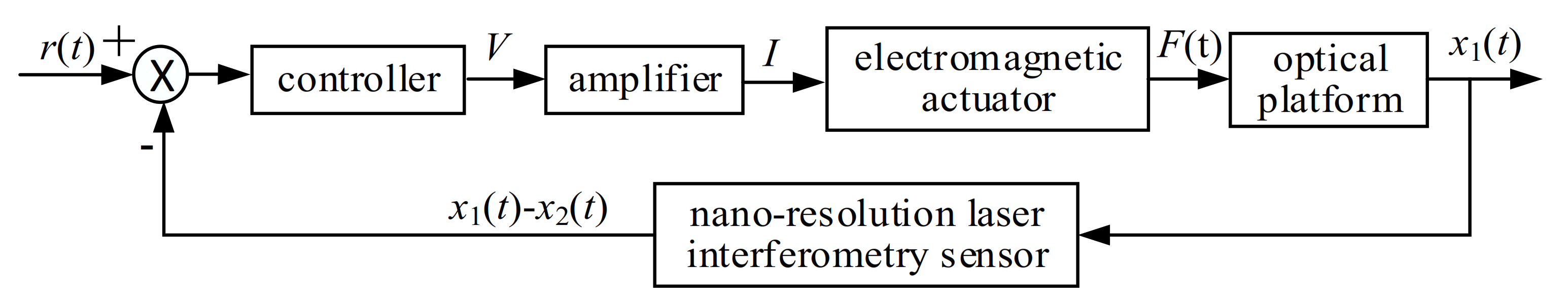
The control block diagram of the electromagnetic actuator is shown in Figure 15. An analog control voltage V is the output according to the displacement of the optical platform relative to the ground, an amplifier converts the control voltage V into driven current I, and drives the electromagnetic actuator to exert force F(t) on the optical platform.
4. Experiments
4.1. Experimental Setup
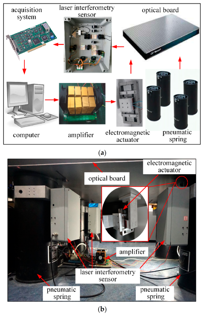
An experimental setup shown in Figure 16 was established to validate the effectiveness of the proposed method. Four EANSGs are added to the optical platform that was composed of a 437 kg optical board and four uniformly arranged pneumatic springs. Each EANSG was configured in parallel with a pneumatic spring, i.e., they together formed a LFPEI. The displacement of the optical board was measured by four developed laser interferometry sensors whose target mirrors were fixed at the bottom of the optical board. A multi-channel signal acquisition system was used to sample the signals of four laser interferometry sensors. Four analog control voltages were output according to the feedback coefficient of the relative displacement strategy to a power amplifier. A self-made multi-channel linear bidirectional power amplifier converted the control voltage into driven currents and drove four electromagnetic actuators to produce negative stiffness characteristics. The amplifier had a range of −1 A~+1 A, a linearity of 0.1‰, a resolution of 0.03 mA, and an amplification factor of 0.1 A/V.
4.2. Natural Frequency Experiment
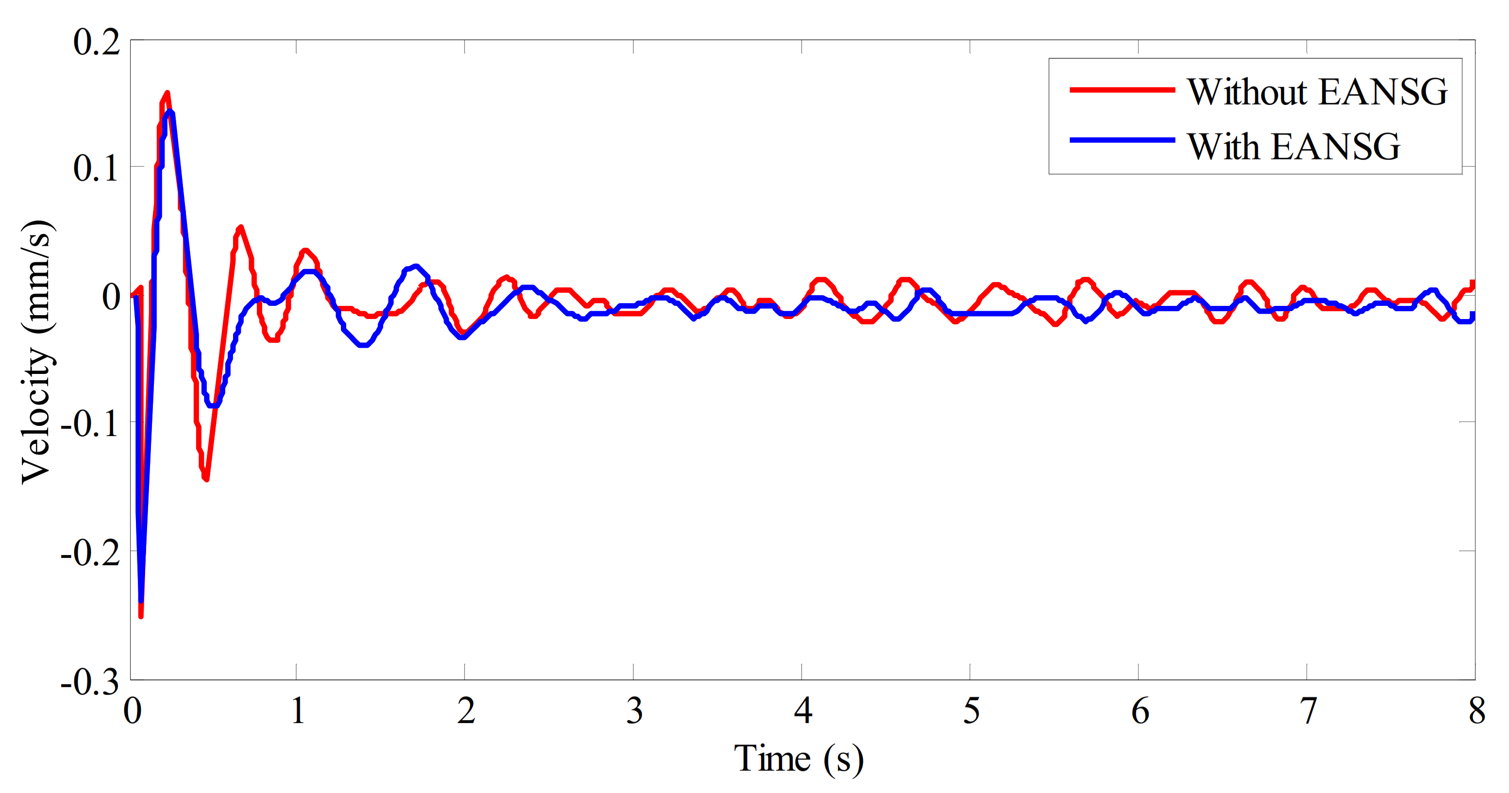
The natural frequency of the optical platform is measured to validate the effectiveness of the proposed EANSG method in the frequency domain. Two comparative experiments were performed using a rubber hammer to produce an impact vibration excitation on the top of the optical platform. In the first experiment, the natural frequency of the optical platform supported only by pneumatic springs is tested. Then, natural frequency of the optical platform supported by four LFPEIs was measured for comparison in the second experiment. Theoretically, the natural frequency of the optical platform can be derived from its displacement impact response, or velocity impact response, or acceleration impact response [32]. The velocity impact response at the center of the optical platform was measured by a low-frequency velocity-type vibration sensor and sampled by a multi-channel signal acquisition system. The experimental results are shown in Figure 17.
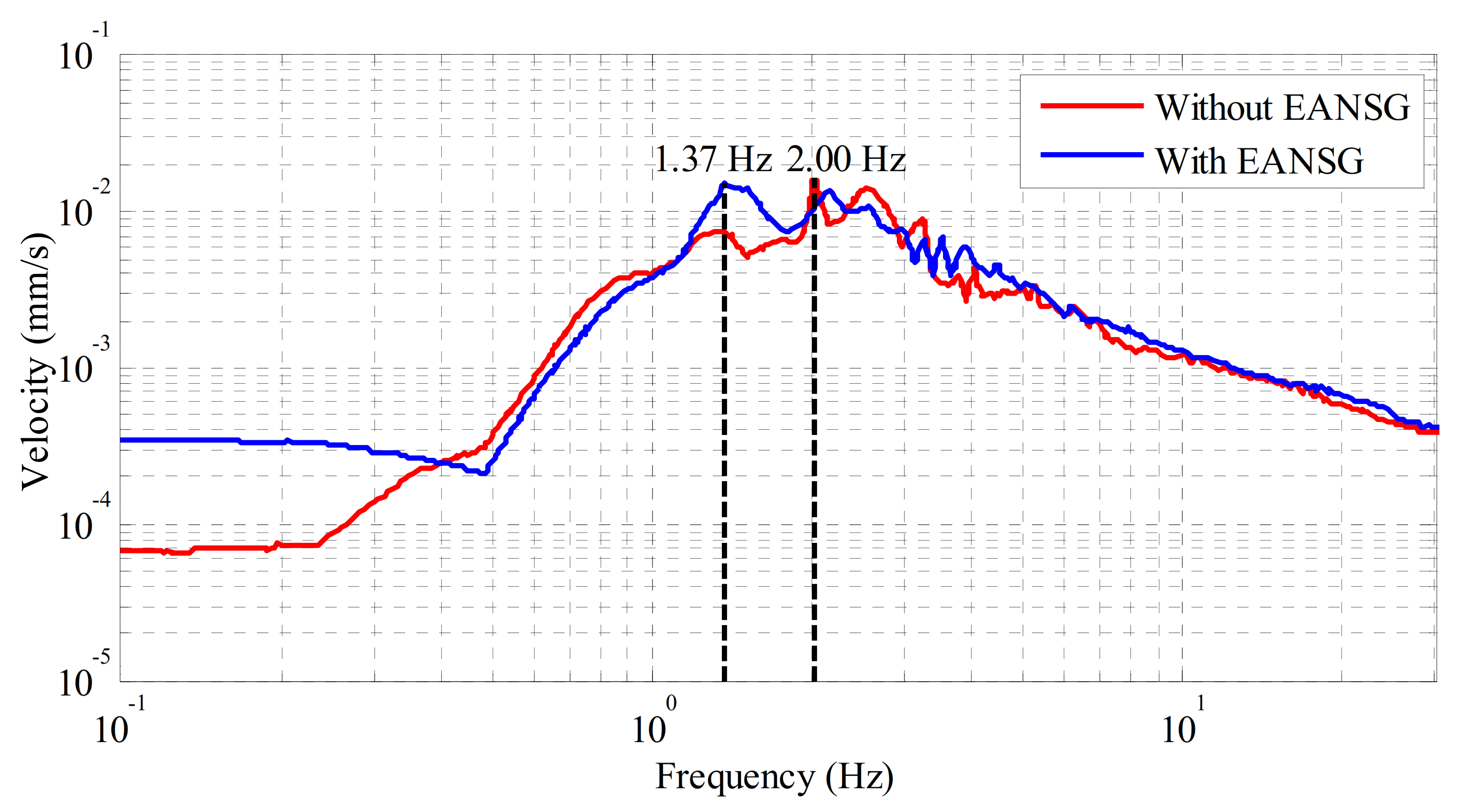
Figure 18 shows the spectrum analysis of the measured velocity impact responses. It can be seen that the natural frequency of the optical platform supported by four pneumatic springs was 2.00 Hz, while that of the optical platform supported by four developed LFPEIs was reduced to 1.37 Hz, decreased by 31.50%, which proved that the proposed EANSG method is effective in counteracting the positive stiffness of pneumatic springs and enhancing the low frequency vibration isolation performance of the optical platform.
4.3. Time Domain Displacement and Velocity Experiments
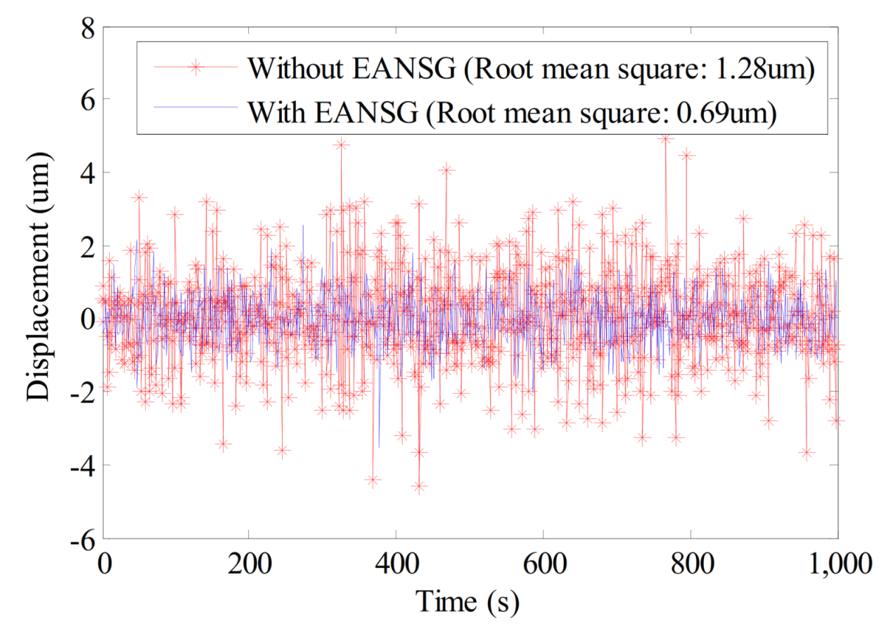
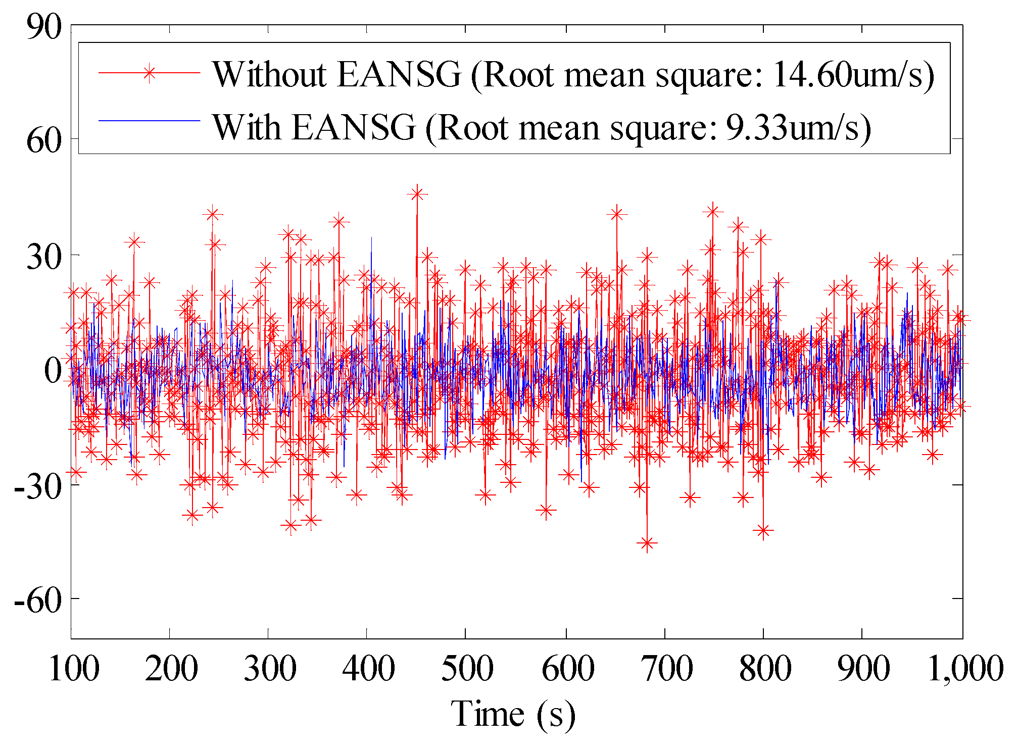
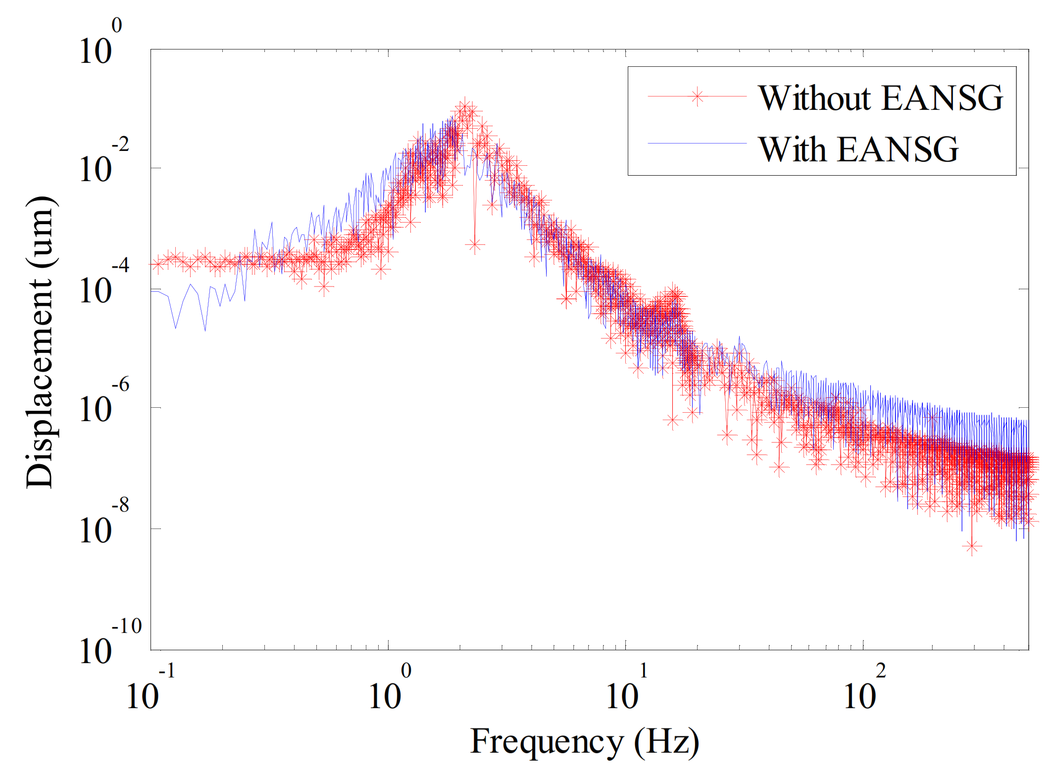
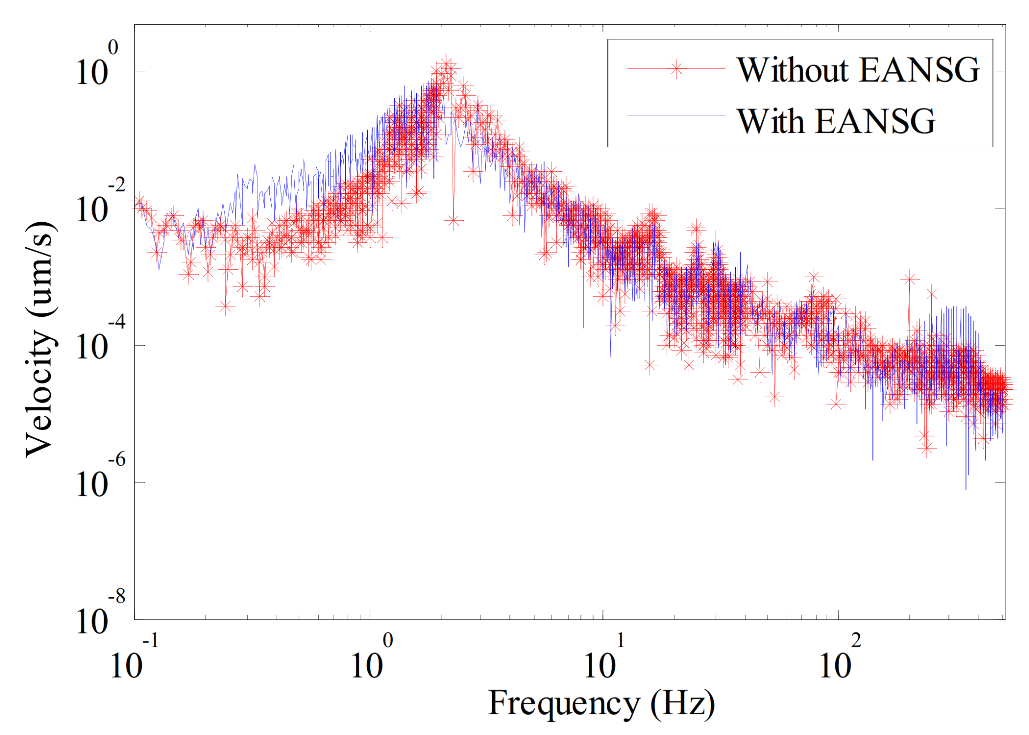
The displacement and velocity at the center of the optical platform supported by either four pneumatic springs or four LFPEIs, i.e., without EANSG and with EANSG under environmental random excitations, were measured in the time domain. As shown in Figure 19 and Figure 20, the displacement and velocity of the optical platform were reduced significantly after the adoption of EANSG. The root mean square of displacement was decreased from 1.28 to 0.69 μm, and the root mean square of velocity was decreased from 14.60 to 9.33 μm/s. Figure 21 and Figure 22 show that the vibration amplitude in the resonance region was reduced by ~6 dB (~50%), while the vibration amplitude in the high frequency range (above 20 Hz) was a bit higher. All these results further demonstrate the effectiveness of the proposed method in the time domain.
5. Conclusions
An EANSG method was proposed to reduce the natural frequency of an optical platform and improve its low-frequency vibration isolation performance. Nano-resolution laser interferometry sensors were proposed and developed to monitor and feedback the micro-vibration of the optical platform, and precision electromagnetic actuators were developed to counteract the positive stiffness of pneumatic springs by actively generating negative-stiffness using a relative displacement feedback strategy. The principle and design of the EANSG are detailed as presented, and the effectiveness of the method was validated by experiments. The spectrum analysis of the impact response experimental results indicate that the natural frequency of the optical platform decreased from 2.00 to 1.37 Hz. The time domain displacement and velocity experimental results indicate that the of vibration displacement decreased from 1.28 to 0.69 μm, the root mean square of the vibration velocity decreased from 14.60 to 9.33 μm/s. Therefore, it can be concluded that the proposed method can effectively enhance the low-frequency vibration isolation performance of optical platforms, and can be applied in the fields requiring better low-frequency vibration isolation performance, such as advanced manufacturing, cutting-edge scientific research. Our future work will focus on the nonlinear feedback control of EANSG.
Author Contributions
Conceptualization, Y.Z. and J.C.; funding acquisition, J.C.; methodology, Y.Z. and J.C.; project administration, J.C. and L.Z.; software, Y.Z. and J.Z.; validation, J.Z., X.B.; writing—original draft, Y.Z. All authors have read and agreed to the published version of the manuscript.
Funding
This research was funded by National Natural Science Foundation of China, grant number 51675139, L1924059 and the Fundamental Research Funds for The Central Universities.
Conflicts of Interest
The authors declare no conflict of interest.
References
- Ibrahim, R. Recent advances in nonlinear passive vibration isolators. J. Sound Vib. 2008, 314, 371–452. [Google Scholar] [CrossRef]
- Platus, D.L. Negative-stiffness-mechanism vibration isolation systems. Proc. SPIE Int. Soc. Opt. Eng. 1999, 3786, 44–54. [Google Scholar]
- Xu, D.; Yu, Q.; Zhou, J.; Bishop, S.R. Theoretical and experimental analyses of a nonlinear magnetic vibration isolator with quasi-zero-stiffness characteristic. J. Sound Vib. 2013, 332, 3377–3389. [Google Scholar] [CrossRef]
- Carrella, A.; Brennan, M.J.; Waters, T.P. Static analysis of a passive vibration isolator with quasi-zero-stiffness characteristic. J. Sound Vib. 2007, 301, 678–689. [Google Scholar] [CrossRef]
- Carrella, A.; Brennan, M.J.; Waters, T.P.; Lopes, V., Jr. Force and displacement transmissibility of a nonlinear isolator with high-static-low-dynamic-stiffness. Int. J. Mech. Sci. 2012, 55, 22–29. [Google Scholar] [CrossRef]
- Wang, X.; Liu, H.; Chen, Y.; Gao, P. Beneficial stiffness design of a high-static-low-dynamic -stiffness vibration isolator based on static and dynamic analysis. Int. J. Mech. Sci. 2018, 142–143, 235–244. [Google Scholar] [CrossRef]
- Wang, X.; Zhou, J.; Xu, D.; Ouyang, H.; Duan, Y. Force transmissibility of a two-stage vibration isolation system with quasi-zero stiffness. Nonlinear. Dyn. 2017, 87, 633–646. [Google Scholar] [CrossRef]
- Yao, Y.; Wang, X.; Li, H. Design and analysis of a high-static-low-dynamic stiffness isolator using the cam-roller-spring mechanism. J. Vib. Acoust. 2020, 142, 1–9. [Google Scholar] [CrossRef]
- Zhang, W.; Zhao, J. Analysis on nonlinear stiffness and vibration isolation performance of scissor-like structure with full types. Nonlinear. Dyn. 2016, 86, 17–36. [Google Scholar] [CrossRef]
- Carrella, A.; Brennan, M.J.; Waters, T.P.; Shin, K. On the design of a high-static-low-dynamic stiffness isolator using linear mechanical springs and magnets. J. Sound Vib. 2008, 315, 712–720. [Google Scholar] [CrossRef]
- Dong, G.; Zhang, X.; Luo, Y.; Zhang, Y. Investigation on the design of magnetic spring-beam vibration isolator with negative stiffness characteristic. Int. J. Appl. Electromagn. Mech. 2016, 52, 1321–1329. [Google Scholar] [CrossRef]
- Wu, W.; Chen, X.; Shan, Y. Analysis and experiment of a vibration isolator using a novel magnetic spring with negative stiffness. J. Sound Vib. 2014, 333, 2958–2970. [Google Scholar] [CrossRef]
- Oyelade, A.O.; Wang, Z.; Hu, G. Dynamics of 1D mass-spring system with a negative stiffness spring realized by magnets: Theoretical and experimental study. Theor. Appl. Mech. Lett. 2017, 7, 17–21. [Google Scholar] [CrossRef]
- Robertson, W.S.; Kidner, M.R.F.; Cazzolato, B.S.; Zander, A.C. Theoretical design parameters for a quasi-zero stiffness magnetic spring for vibration isolation. J. Sound Vib. 2009, 326, 88–103. [Google Scholar] [CrossRef]
- Yan, B.; Ma, H.; Zhao, C.; Wu, C.; Wang, K.; Wang, P. A vari-stiffness nonlinear isolator with magnetic effects: Theoretical modeling and experimental verification. Int. J. Mech. Sci. 2018, 148, 745–755. [Google Scholar] [CrossRef]
- Dong, G.; Zhang, X.; Xie, S.; Yan, B.; Luo, Y. Simulated and experimental studies on a high-static-low-dynamic stiffness isolator using magnetic negative stiffness spring. Mech. Syst. Signal. Process. 2017, 86, 188–203. [Google Scholar] [CrossRef]
- Zhou, Z.; Chen, S.; Xia, D.; He, J.; Zhang, P. The design of negative stiffness spring for precision vibration isolation using axially magnetized permanent magnet rings. J. Vib. Control 2019, 25, 2667–2677. [Google Scholar] [CrossRef]
- Shan, Y.; Wu, W.; Chen, X. Design of a miniaturized pneumatic vibration isolator with high-static-low- dynamic stiffness. J. Vib. Acoust. 2015, 137. [Google Scholar] [CrossRef]
- Zheng, Y.; Zhang, X.; Luo, Y.; Yan, B.; Ma, C. Design and experiment of a high-static-low-dynamic stiffness isolator using a negative stiffness magnetic spring. J. Sound Vib. 2016, 360, 31–52. [Google Scholar] [CrossRef]
- Gao, X.; Chen, Q. Nonlinear analysis, design and vibration isolation for a bilinear system with time-delayed cubic velocity feedback. J. Sound Vib. 2014, 333, 1562–1576. [Google Scholar] [CrossRef]
- Cheng, C.; Li, S.; Wang, Y.; Jiang, X. On the analysis of a high-static-low-dynamic stiffness vibration isolator with time-delayed cubic displacement feedback. J. Sound Vib. 2016, 378, 76–91. [Google Scholar] [CrossRef]
- Palomares, E.; Nieto, A.J.; Morales, A.L; Chicharro, J.M.; Pintado, P. Numerical and experimental analysis of a vibration isolator equipped with a negative stiffness system. J. Sound Vib. 2018, 414, 31–42. [Google Scholar] [CrossRef]
- Churchill, C.B.; Shahan, D.W.; Smith, S.P.; Keefe, A.C.; McKnight, G.P. Dynamically variable negative stiffness structures. Sci. Adv. 2016, 2, e1500778. [Google Scholar] [CrossRef] [PubMed] [Green Version]
- Zhou, N.; Liu, K. A tunable high-static-low dynamic stiffness vibration isolator. J. Sound Vib. 2010, 329, 1254–1273. [Google Scholar] [CrossRef]
- Han, C.; Liu, X.; Wu, M.; Liang, W. A new approach to achieve variable negative stiffness by using an electromagnetic asymmetric tooth structure. Shock. Vib. 2018, 5, 1–11. [Google Scholar] [CrossRef] [Green Version]
- Pu, H.; Yuan, S.; Peng, Y.; Meng, K.; Zhao, J.; Xie, R.; Huang, Y.; Sun, Y.; Yang, Y.; Xie, S.; et al. Multi-layer electromagnetic spring with tunable negative stiffness for semi-active vibration isolation. Mech. Syst. Signal. Process. 2019, 121, 942–960. [Google Scholar] [CrossRef]
- Sun, Y.; Meng, K.; Yuan, S.; Zhao, J.; Xie, R.; Yang, Y.; Luo, J.; Peng, Y.; Xie, S.; Pu, H. Modeling electromagnetic force and axial-stiffness for an electromagnetic negative-stiffness spring toward vibration isolation. IEEE Trans. Magn. 2019, 55, 1–10. [Google Scholar] [CrossRef]
- Wang, K.; Zhou, J.; Ouyang, H.; Cheng, L.; Xu, D. A semi-active metamaterial beam with electromagnetic quasi-zero - stiffness resonators for ultralow frequency band gap tuning. Int. J. Mech. Sci. 2020, 176, 105548. [Google Scholar] [CrossRef]
- Zhang, F.; Shao, S.; Tian, Z.; Xu, M.; Xie, S. Active-passive hybrid vibration isolation with magnetic negative stiffness isolator based on Maxwell normal stress. Mech. Syst. Signal Process. 2019, 123, 244–263. [Google Scholar] [CrossRef]
- Zhao, G.; Ding, B.; Watchi, J.; Deraemaeker, A.; Collette, C. Experimental study on active seismic isolation using interferometric inertial sensors. Mech. Syst. Signal. Process. 2020, 145, 106959. [Google Scholar] [CrossRef]
- Kim, M.H.; Kim, H.Y.; Kim, H.C.; Ahn, D.; Gweon, D.-G. Design and control of a 6-DOF active vibration isolation system using a Halbach magnet array. IEEE ASME T. Mechatron. 2016, 21, 2185–2196. [Google Scholar] [CrossRef]
- Gordon, C.G. Generic criteria for vibration-sensitive equipment. Proc. SPIE Int. Soc. Opt. Eng. 1992, 1619, 71–85. [Google Scholar]
Figure 1.
Scheme of electromagnetic active-negative stiffness generator (EANSG).

Figure 2.
Force–displacement curves indicating the principle of EANSG.

Figure 3.
Scheme and design of the proposed nano-resolution laser interferometry sensor: (a) scheme of nano-resolution laser interferometry sensor and (b) the design of the nano-resolution laser interferometry sensor: HWP1, first half-wave plate; HWP2, second half-wave plate; PBS1, first polarizing beam splitter; PBS2, second polarizing beam splitter; PBS3, third polarizing beam splitter; RM, reference mirror; TM, target mirror; QWP1, first quarter-wave plate; QWP2, second quarter-wave plate; QWP3, third quarter-wave plate; NBS, non-polarizing beam splitter; PD, photodiode; CL, convex lenses.

Figure 4.
Experimental setup for resolution and stability test.

Figure 5.
Resolution of the laser interferometry sensor.

Figure 6.
Stability of the laser interferometry sensor.

Figure 7.
Principle of the proposed electromagnetic actuator: (a) scheme of electromagnetic actuator; and (b) the simplified two-dimensional structure.
Figure 7.
Principle of the proposed electromagnetic actuator: (a) scheme of electromagnetic actuator; and (b) the simplified two-dimensional structure.

Figure 8.
Photo of the electromagnetic actuator prototype.

Figure 9.
Experimental setup for the magnetic flux density test.

Figure 10.
Experimental results of the magnetic flux density.

Figure 11.
Magnetic force–drive current curved surface of the electromagnetic actuator.

Figure 12.
Step response curve of the amplifier.

Figure 13.
Bandwidth test curve of the amplifier.

Figure 14.
Scheme of relative displacement feedback.

Figure 15.
Control block diagram of the electromagnetic actuator.

Figure 16.
Experimental setup for the EANSG method validation: (a) sketch of the experimental setup and (b) a photo of the experimental setup.
Figure 16.
Experimental setup for the EANSG method validation: (a) sketch of the experimental setup and (b) a photo of the experimental setup.

Figure 17.
Velocity impact responses of the optical platform supported by either pneumatic springs or low frequency performance enhanced isolators (LFPEIs).
Figure 17.
Velocity impact responses of the optical platform supported by either pneumatic springs or low frequency performance enhanced isolators (LFPEIs).

Figure 18.
Spectrum analysis of the measured velocity impact responses.

Figure 19.
Experimental results of displacement.

Figure 20.
Experimental results of velocity.

Figure 21.
Spectrum analysis of displacement.

Figure 22.
Spectrum analysis of velocity.


Table 1.
Geometric parameters of an electromagnetic actuator.
| l(mm) | hm(mm) | Tm(mm) | h(mm) | lse(mm) | Ts(mm) | Ty(mm) | lg(mm) | n |
| 40 | 15 | 30 | 7 | 17 | 3 | 8 | 70 | 220 |
Publisher’s Note: MDPI stays neutral with regard to jurisdictional claims in published maps and institutional affiliations. |
© 2020 by the authors. Licensee MDPI, Basel, Switzerland. This article is an open access article distributed under the terms and conditions of the Creative Commons Attribution (CC BY) license (http://creativecommons.org/licenses/by/4.0/).
Share and Cite
MDPI and ACS Style
Zhao, Y.; Cui, J.; Zhao, J.; Bian, X.; Zou, L. Improving Low Frequency Isolation Performance of Optical Platforms Using Electromagnetic Active-Negative-Stiffness Method. Appl. Sci. 2020, 10, 7342. https://doi.org/10.3390/app10207342
AMA Style
Zhao Y, Cui J, Zhao J, Bian X, Zou L. Improving Low Frequency Isolation Performance of Optical Platforms Using Electromagnetic Active-Negative-Stiffness Method. Applied Sciences. 2020; 10(20):7342. https://doi.org/10.3390/app10207342
Chicago/Turabian StyleZhao, Yamin, Junning Cui, Junchao Zhao, Xingyuan Bian, and Limin Zou. 2020. "Improving Low Frequency Isolation Performance of Optical Platforms Using Electromagnetic Active-Negative-Stiffness Method" Applied Sciences 10, no. 20: 7342. https://doi.org/10.3390/app10207342
Note that from the first issue of 2016, this journal uses article numbers instead of page numbers. See further details here.