Static Behaviors of a Long-span Cable-Stayed Bridge with a Floating Tower under Dead Loads


1
School of Civil, Environmental and Architectural Engineering, Korea University, Seoul 02841, Korea
2
Coastal and Ocean Engineering Division, Korea Institute of Ocean Science and Technology, Busan 49111, Korea
*
Author to whom correspondence should be addressed.
J. Mar. Sci. Eng. 2020, 8(10), 816; https://doi.org/10.3390/jmse8100816
Submission received: 14 September 2020
/
Revised: 13 October 2020
/
Accepted: 15 October 2020
/
Published: 20 October 2020
(This article belongs to the Special Issue Ocean and Shore Technology (OST))
Abstract
:Owing to the structural characteristics of floating-type structures, they can be effectively applied to overcome the limitation of conventional long-span bridges in deep water. Unlike cable-supported bridges with fixed towers, floating cable-supported bridges show relatively large displacements and rotations under the same load because of floating towers; moreover, the difference in the support stiffness causes differences in the behavior of the superstructures. In addition, the risk of overturning is greater than in conventional floating offshore structures because the center of gravity of the tower is located above the buoyancy center of the floater. A floating cable-supported bridge in which the tether supports the floating main tower is directly influenced by the tether arrangement, which is very important for the stability of the entire structure. In this study, according to the inclined tether arrangement, the outer diameter of the floater, and the buoyancy vertical load ratio (BVR), the static behavioral characteristics of the long-span cable-stayed bridges with floating tower are evaluated through nonlinear finite-element analysis. When the intersection of the tension line of the tether and a pivot point of the tower coincide, the tethers can no longer resist the tower’s rotation. For this reason, a large displacement occurs to equilibrate the structure, and further increases as it approaches the specific slope, even if it is not exactly the specific tether slope. The analytical model of this study indicates that, in terms of increasing the rotational stiffness of the main tower, it is advantageous to increase the floater diameter until a BVR of 1.8 is reached and to increase the axial stiffness of the tether from a BVR of 2.0 or higher.
1. Introduction
A traditional sea-crossing bridge is generally designed as a long-span bridge to secure the driving route of ships and reduce the cost and construction period of piers. The span length of the bridge is determined by the tower, foundation, and ground conditions. However, there are technical and economical limitations to the construction of sea-crossing bridges in deep water.
A cable-supported bridge with a floating tower does not require a fixed pier on the seabed and is a structural type that can overcome the limitations in deep water because the main tower of the cable bridge is supported by the buoyancy produced by a floating body. The current floating bridge is a multi-span continuous bridge with a very short span. So far, no floating bridges with very long spans have been built.
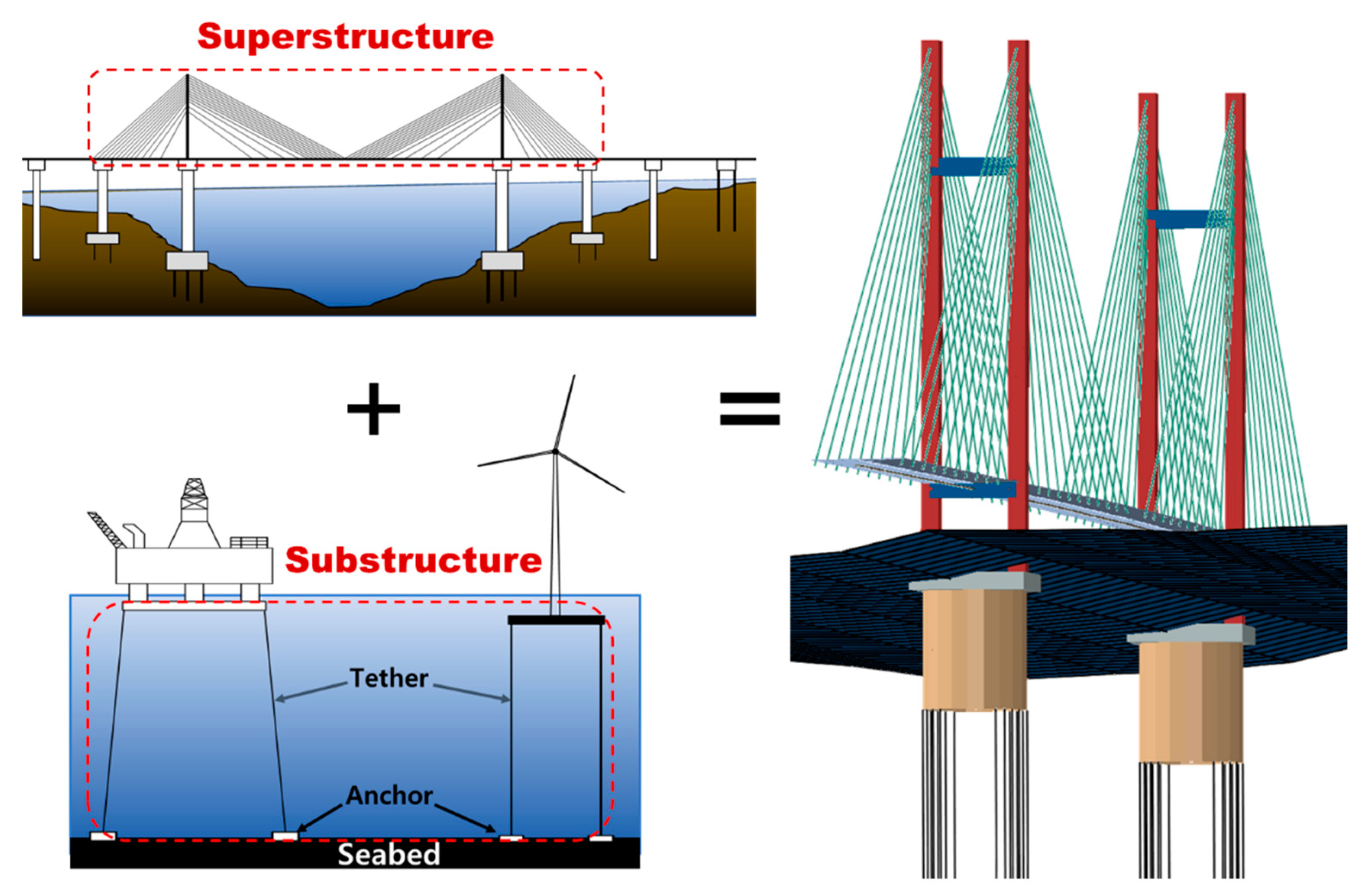
The superstructure of a cable-supported bridge with a floating tower, as shown in Figure 1, is the same as that of a general fixed cable-supported bridge, and the tower supporting the cable and girder is supported by a floating body. Through many previous studies, the fixed cable type of the upper structure has been verified, and the floating type of the offshore structure is already used in the tension leg platform (TLP) type at a depth of 1000 m or more. The two structural types have been sufficiently verified, and if the safety and stability of the tower supported by the floating body are secured, it can be sufficiently used as a floating long-span cable bridge. The proposed long-span cable-stayed bridge with floating towers can be constructed with well-known technology, which will be the most suitable long-span sea-crossing bridge technology in deep depths.
The TLP type is mainly a floating support type for offshore structures including offshore oil and gas platforms and submerged floating tunnels [1,2,3]. Vertical and buoyant forces acting on a structure form a balance of forces by using the buoyancy of a floating body submerged in water. A cable-supported bridge with a floating tower has been proposed to control the displacement of cable-stayed bridges by tethers connected to the seabed using TLP type and to compensate for the disadvantages of sea-crossing bridges [4]. Unlike fixed tower bridges or small span floating bridges [5], cable-stayed bridges with floating towers additionally moor the floater connected to the towers, tending to show a more complex nonlinear structural behavior due to the tether–tower–cable–girder interaction. For the purpose of transportation, cable-stayed bridges with floating towers require additional horizontal displacement control, as well as vertical displacement, which is important for conventional floating structures. Unlike the conventional TLP-type floating structure, it is important to analyze the overall behavior of the structure according to the tether arrangement, for additional horizontal displacement control [6], and there have been no results of parameter analysis for various tether arrangements. Various analysis techniques and analytical studies have been conducted on floating bridges. However, most of these [7,8] have mainly focused on floating bridges in the form of short-span continuous bridges that ships cannot pass.
Papinutti [9] used time-domain tools to analyze the coupled wind and wave load responses of a long-span floating suspension bridge. For the initial screening analysis, a frequency-domain analysis was conducted to investigate the critical combination of wind events of a TLP suspension bridge [10]. In addition, the effects of extreme and irregular wind and wave loads on the dynamic behaviors of the cable supported bridges with floating pylons were studied by numerical simulation in frequency-and time-domain [11,12]. In the study centered on the E39 project in Norway, the floating suspension bridge model was studied and the environmental conditions in the E39 region were found to be relatively mild. Kim et al. [13] provided an overview of the main hydrodynamic analysis techniques for cable-supported bridges with floating towers. Kim et al. [14] studied a tether’s short-term fatigue under severe environmental conditions according to various tether slopes. Studies on such floating cable bridges have been actively conducted in recent years. However, research on various parameters and floating cable-stayed bridges using the tether’s slope arrangement is still insufficient.
In this study, a nonlinear analysis is conducted to investigate the static behavioral characteristics of a cable-stayed bridge with floating towers, considering various initial inclination arrangements of tethers, buoyancy-vertical load ratios, and outer diameters (ODs) of floaters. A total of 755 nonlinear analyses are performed using the parameters such as OD of the floating body, tether slope, and initial buoyancy ratio parameters to confirm the complex nonlinear global system interaction behavior of the cable-stayed bridge with floating towers.
2. Analysis Method for Investigating the Structural Behavior of Floating Cable-Stayed Bridges
This section presents details of the analysis method for investigating the static structural behavior of floating cable-stayed bridges. The prototype models of the floating cable-stayed bridge were modeled refer to the cable-stayed bridge models studied by Kim et al. [14]. To consider various geometric nonlinearities of the bridges, a nonlinear finite-element analysis was mainly conducted. To model the main structural members of the structure, such as girders, towers, floaters, stay cables, and tethers, nonlinear beam truss elements were used. For the nonlinear analysis, an incremental-iterative analysis based on the Newton–Rapshon method was conducted. For the analytical study, dead loads estimated by the structure’s self-weight were applied, and the analytical model was assumed to be a six-lane round-trip bridge with reference to the Korean Highway Bridge Design Code [15]. The analysis was performed using ABAQUS V2018 [16].
2.1. Initial Shape Analysis
Before proceeding with the parametric analysis, the initial shape analysis was performed to select an appropriate cable and tether tension. In general, nonlinearity, such as the effect of a sag, the beam-column effect, and a large deformation effect, should be considered in a cable. To accurately represent cable behavior, Irvine [17] presented the theory of a self-weighted two-dimensional elastic suspension line, based on which the elastic suspension cable element has been extensively used to model the main cables of the cable-stayed and suspension bridges. The initial shape determination methods studied to date include the trial-and-error [18], initial member force [19], and TCUD (target configuration under dead load) [20] methods. In the trial-and-error method, the designer changes tension forces of stay cables to determine the optimum initial tension of them; however, it takes considerable time to perform iterative calculation and it is difficult to implement a relatively accurate initial shape. In the first step of the analysis, the initial member force method performs nonlinear analysis in the absence of the initial member force, and from the subsequent steps, assumes a member force obtained through the previous step’s nonlinear analysis as the initial member force, introduces it to the analysis model, and repeats the nonlinear analysis. This means that the analysis method repeats the nonlinear analysis until the desired initial shape is obtained, under the assumed initial member force. However, this method is sensitive to the initial tension. On the other hand, the TCUD analysis method uses elastic suspension cable elements, and beam-column elements. This method, unlike the initial member force method, performs an initial shape analysis by adding the non-stress length of the cable as a variable and constraining the node displacement corresponding to the number [20]. The TCUD analysis method is not sensitive to the initial tension, but in the case of cable-stayed bridges, the displacement caused by the compression force of the tower cannot be controlled.
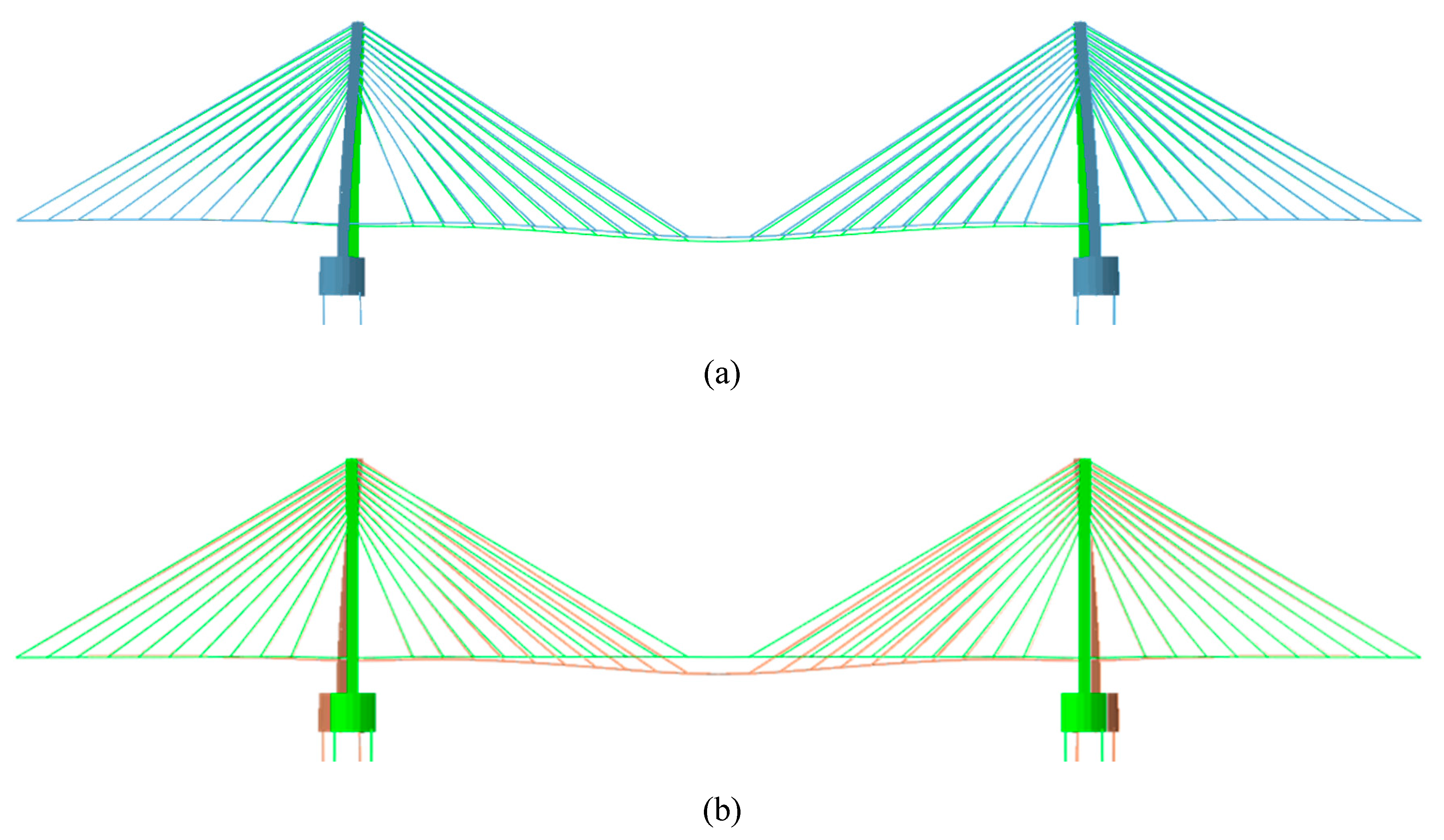
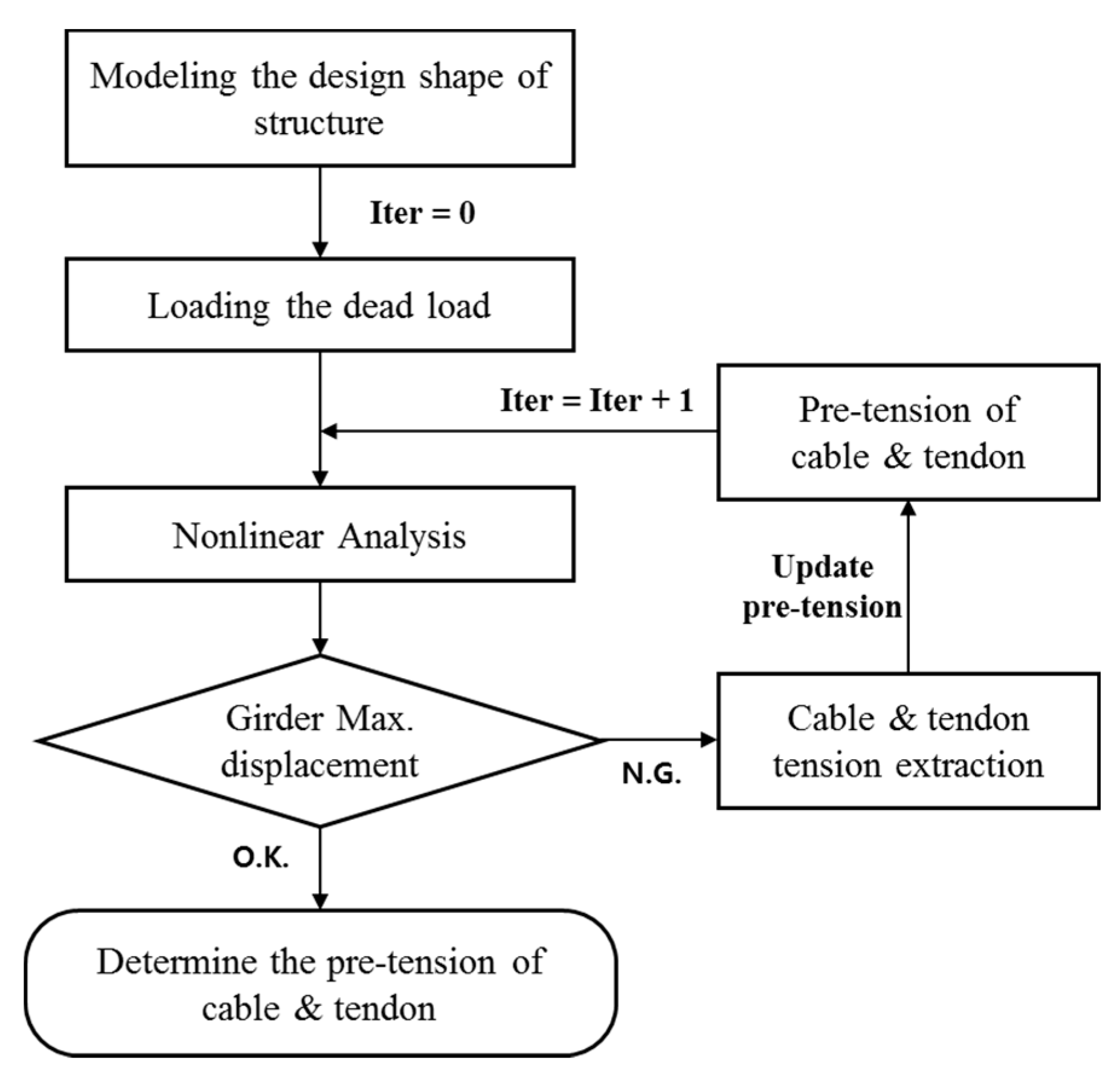
Under the same conditions, the lower part of the tower of the floating cable bridge has a larger displacement than that of the fixed cable bridge, as shown in Figure 2a. In this study, the initial member force method (Figure 3), which is most suitable for a floating cable bridge with relatively large displacement of the tower, was used as the initial shape analysis method
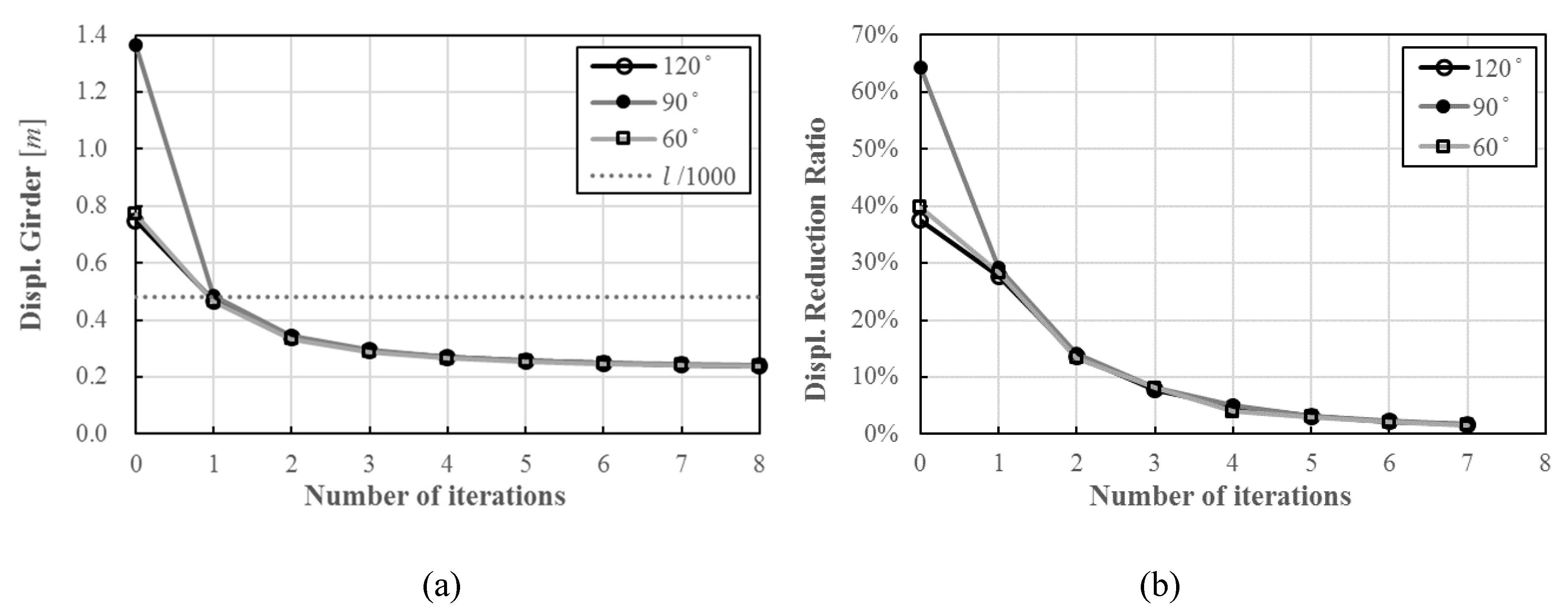
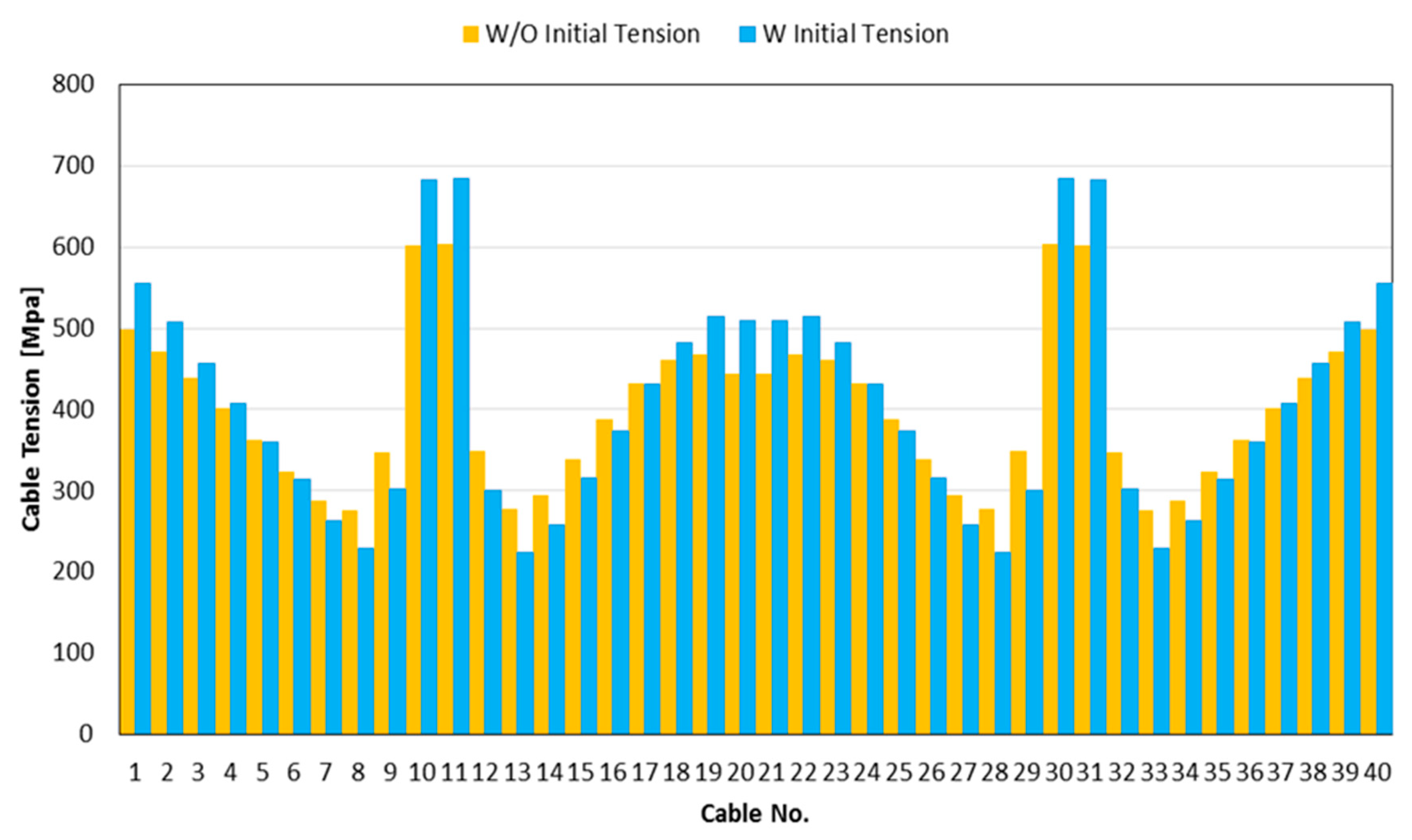
Figure 4 shows the iteration results of the initial shape analysis. Figure 5 shows the result of tension distribution of one-side cables with and without pre-tension. Cables 1 and 40 were cables arranged at both ends. Each tower was located between cables 10 and 11 and between cables 30 and 41.
The maximum vertical displacement of 0 iteration girders without pre-tension was 1.36 m and the maximum vertical displacement of eight-iteration girders applying the tension result of seven iterations was 0.24 m; thus, the vertical displacement of the girders was reduced by 82.4%. The Korean Highway Bridge Design Code [15] is presented as l/1000 (l: span length) as a conservative deflection standard. As shown in Figure 4a, the initial tension must be applied through the initial shape analysis to satisfy the deflection criteria of the girder.
To reduce the influence of initial tension magnitude in the initial member force method, the number of iterations of the initial shape analysis was determined as four, with a tolerance of less than 5%. In this study, the parametric analysis models used the tension results of three iterative nonlinear analyses as the initial tension of the cable-stayed bridge.
2.2. Analysis Model
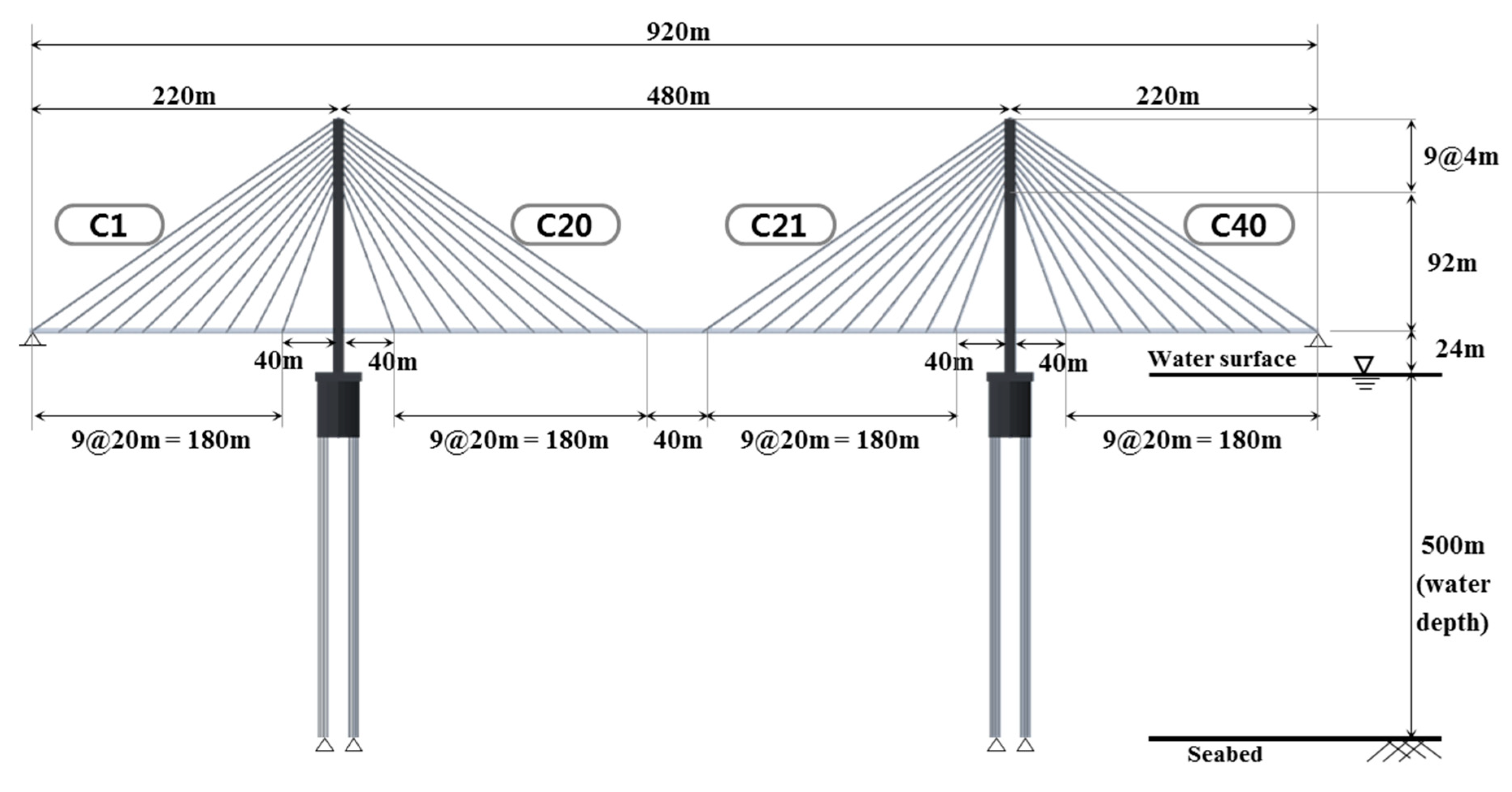
The analytical model for the global static behavior analysis of the cable-stayed bridge with a floating tower is shown in Figure 6. This bridge had a total length of 920 m, a center span of 480 m, a tower height of 128 m (to the top of tower to girder), and free water surface-to-girder spacing of 25 m. The water depth of the analytical model was assumed to be 500 m.
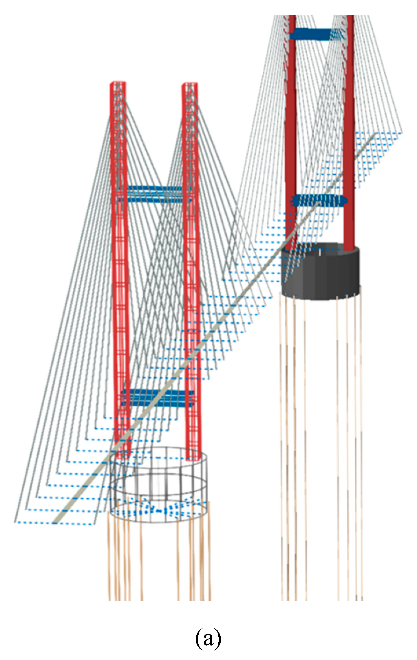
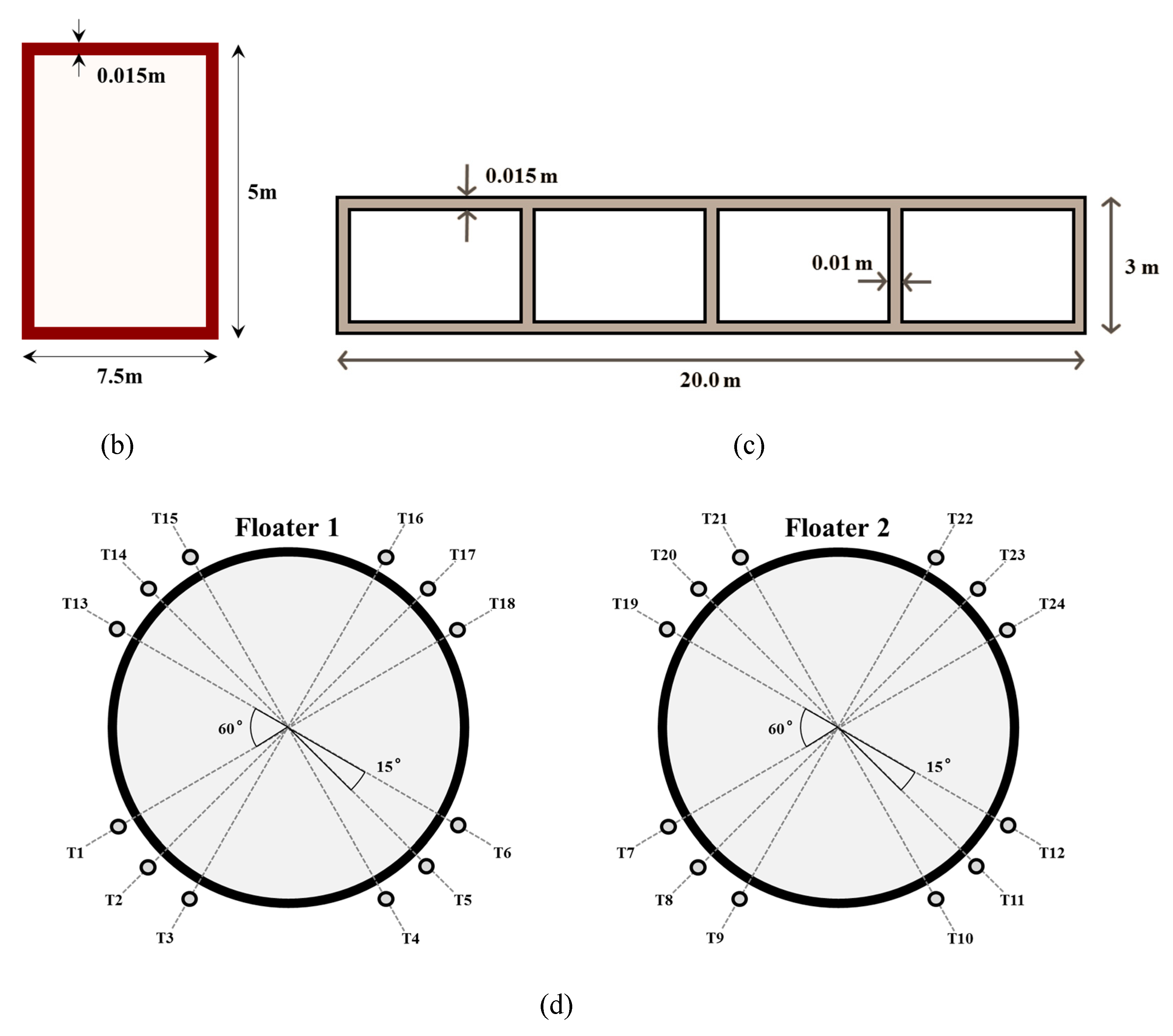
The tower of the analytical model is shown in Figure 7a. The cables showed a two-sided arrangement in the H-type tower of a single box type, as indicated in Figure 7b. The tower and girder used the beam element B31, and the girder was assumed to be mounted on the cross beam of the tower and connected using the ABAQUS [16] MPC-link option. In addition, a hinge connection was assumed between the girder and the cross beam of the tower.
The cross-sectional area of all cables was 0.01 m2 and supported the bridge girder by 80 cables on the two sides. As there are no floating long-span bridges yet built, the girder section of references [21,22], which studied the ultimate behavior of a cable-stayed bridge by analyzing its various parameters, was used. As shown in Figure 7c, the girder was assumed to be a four-cell box section, which assumed sufficient stiffeners and ribs to prevent local buckling. Each submerged floater was a beam element (B31), formed of steel (API X65 grade) and moored with 12 tethers, as shown in Figure 7d. The cable and tether were modeled as truss elements (T3D2) that could not receive compressive and bending force. The floater of the analytical model was assumed to be a watertight 0.04-m-thick cylinder, with its diameter and draft set as the analysis variables.
To take into account the buoyancy of all members submerged in the water, the buoyancy force was modeled by modifying the magnitude and direction of the member’s gravitational acceleration in the analysis. This can be used for further study in which the mass does not change in the dynamic analysis, and the buoyancy always acts opposite to the gravitational acceleration. By calculating the sum of the force of the dead load and the buoyancy considering the submerged volume, the unit weight of the submerged member was fixed, and the buoyancy force was considered by reflecting the corrected acceleration of gravity in the analysis. For members with greater buoyancy than the dead load, the buoyancy force was applied as the dead load by inverting the direction of acceleration of gravity in the analysis.
The rational approach to take into account the restoring moment induced by the change of the buoyancy center of the floater in the heeled condition is required. One effective way to take into account the restoring moment is to use the rotational spring element with a rotational stiffness for the submerged members. In that case, the rotational stiffness of the submerged cylinder can be determined by the equation of the restoring moment of the submerged cylinder in the heeled condition as below:
where =restoring moment of the submerged cylinder in the heeled condition, =water density, =gravity acceleration, =2nd moment of area of the water plane, = angle of heel (roll/pitch)
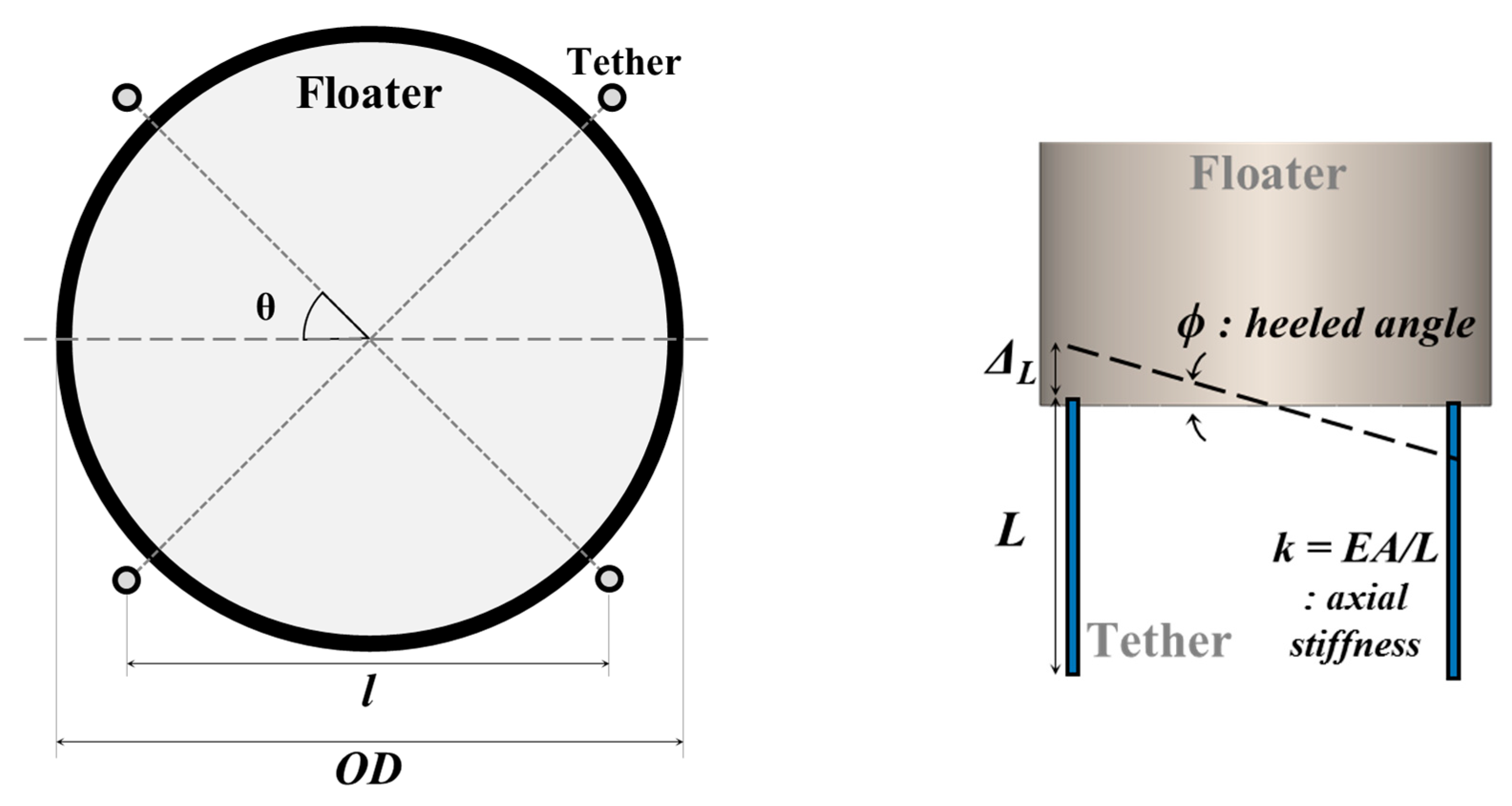
However, it is well known that the restoring moment of the floater moored by tethers is generally induced by the tethers. For the numerical models in this study, the restoring moment induced by the four tethers shown in Figure 8 can be evaluated as below:
where =restoring moment induced by the symmetric tethers (the four tethers shown in Figure 8), =axial stiffness of a tether, =outer diameter of the cylinder, = angle of heel (roll/pitch)
Table 1 shows that the contribution of the tethers on the rotational stiffness. Based on the comparison result, the rotational spring for considering the restoring moment due to the change of the buoyancy center of the floater was not included in the numerical models.
Table 2 shows the main section specifications of the analytical model. Various geometrical parameters were considered to identify the nonlinear global behavior of a fan-type cable-stayed bridge with floating towers
2.3. Considered Parameters
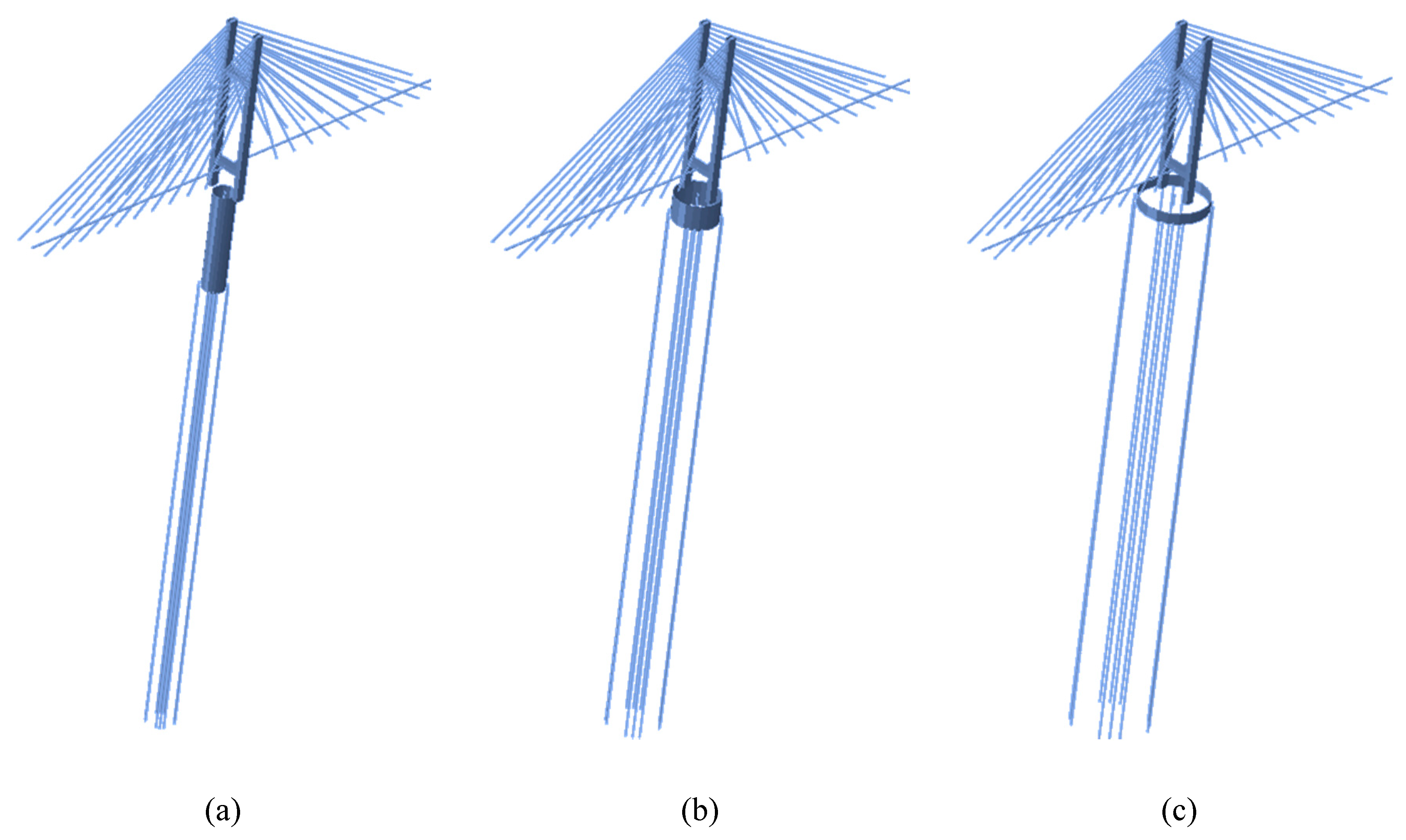
In this study, the effects of the OD on the structural behavior under dead loads were investigated. It can be assumed that the OD directly affects to the rotational stiffness induced by tethers. So, the rational range of the parameter was designed for the case study. The floater thickness and submerged volume were fixed for equal buoyancy, and the OD was set in the range of 20–60 m. It was modeled to have equal submerged volume and buoyancy, by adjusting the submerged depth according to the change in the floater diameter, as shown in Figure 9.
Unlike the conventional TLP-type floating sea-crossing structures with a vertical arrangement of tethers, where vertical displacement control is mainly considered, the cable-supported bridge with a floating tower is a transportation structure that requires proper control of the horizontal displacement. The initial vertical arrangement of tethers causes a relatively large horizontal displacement, as the horizontal stiffness of the tether occurs only when the horizontal displacement of the floater occurs.
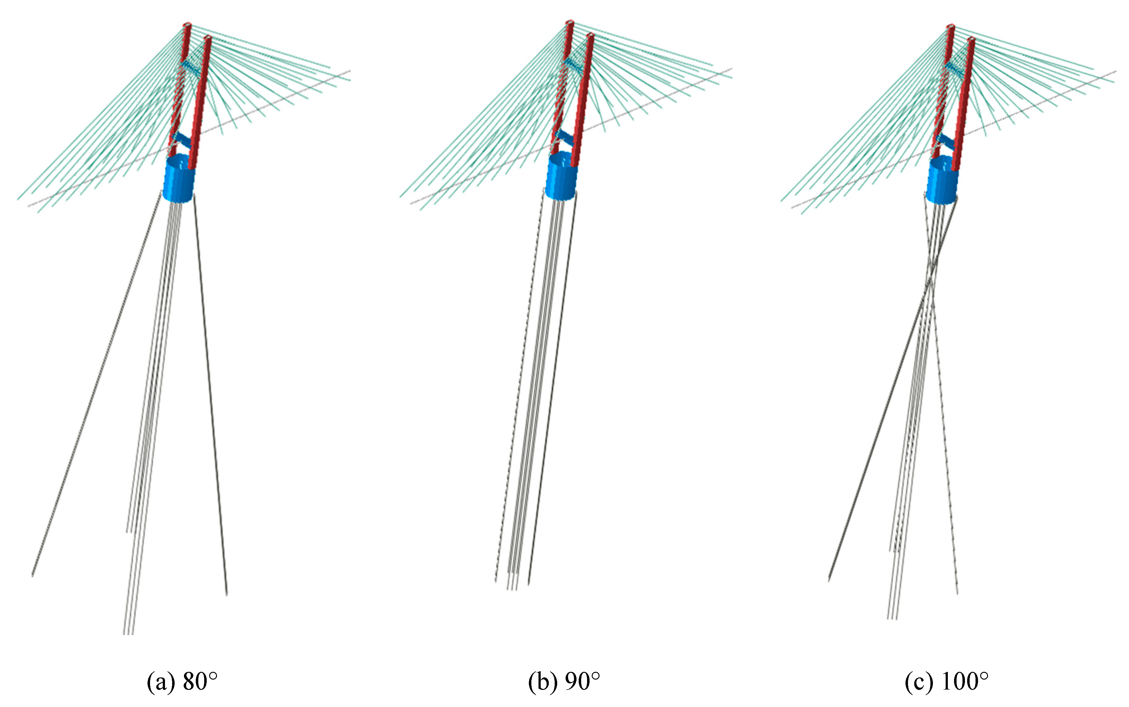
As another analysis parameter, a tether arrangement with various inclinations of the cable-supported bridge with a floating tower was selected. A parametric analysis of 60–120° slope was performed with a 90° slope when the tether arrangement was vertical. To evaluate the global behavior of the structure according to the inclined arrangement of the tethers, which serves as the boundary condition of the superstructure, the initial inclined arrangement of the tether was modeled at the same depth as that shown in Figure 10.
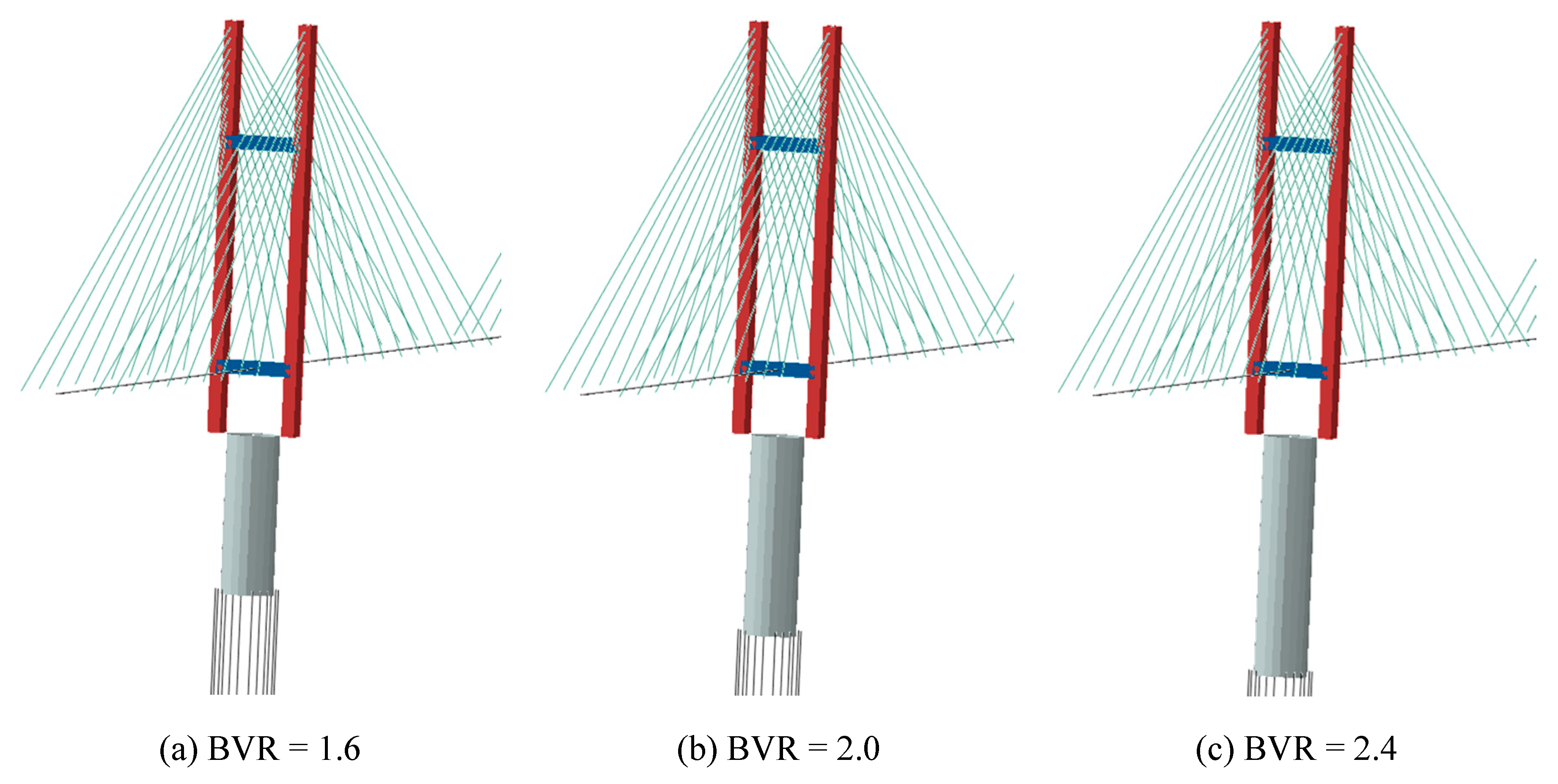
The analysis was performed by selecting the buoyancy-vertical load ratio (BVR) as a variable. A parametric analysis of the BVR was performed by varying the submerged volume of the floater. At this time, the diameter and thickness of the floater were fixed, and the buoyancy ratio was selected as an analysis variable ranging from 1.6 to 2.4 by adjusting the floater’s draft, as shown in Figure 11.
Table 3 shows all the parameters considered in this paper. The number of considered BVR, OD, and inclined arrangement of tethers parameters was 5, 5, and 31, and geometric nonlinear analysis was conducted for all the 775 cases.
3. Static Behavior of Floating Cable-Stayed Bridges under Dead Loads
3.1. Displacement of the Floater
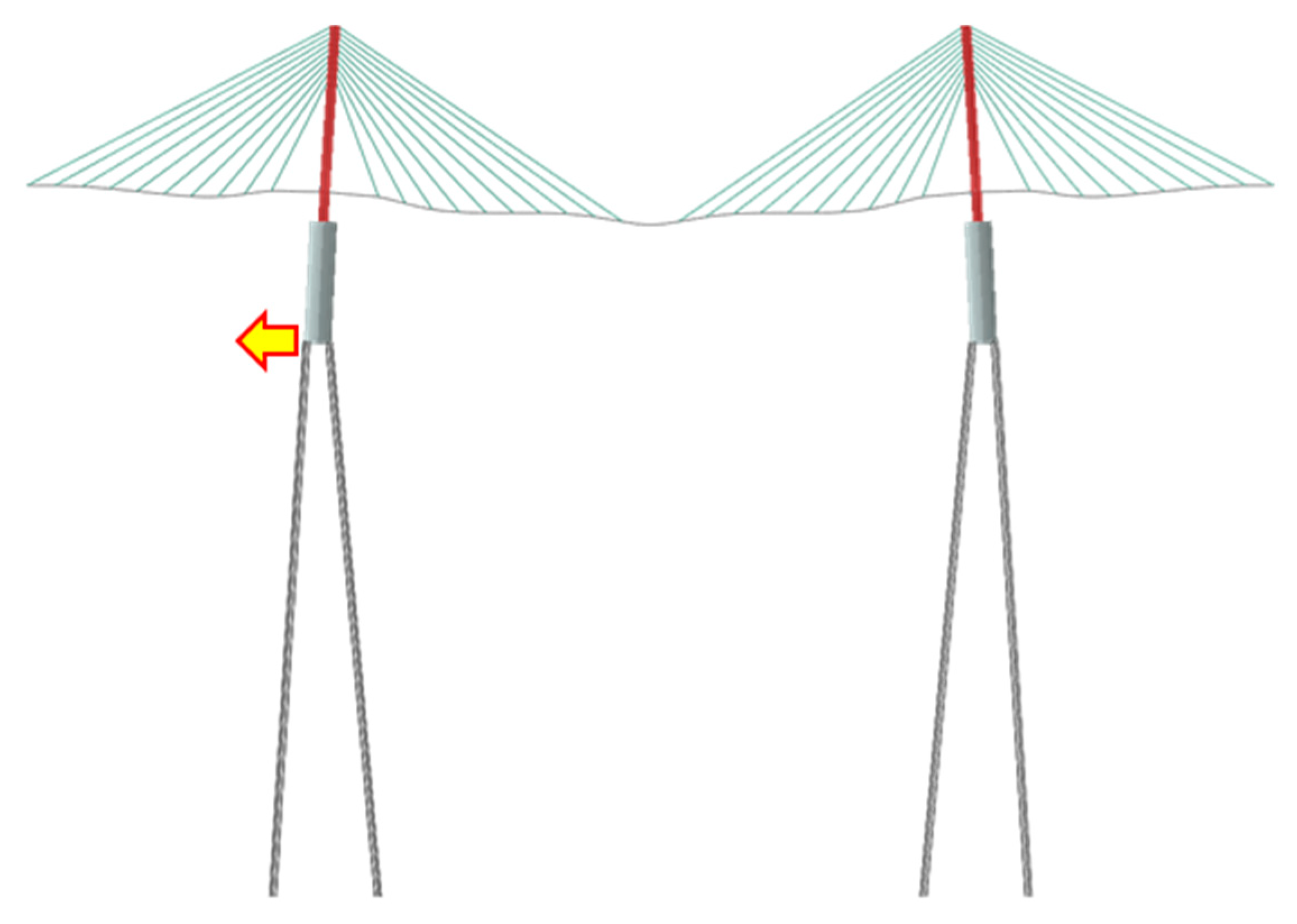
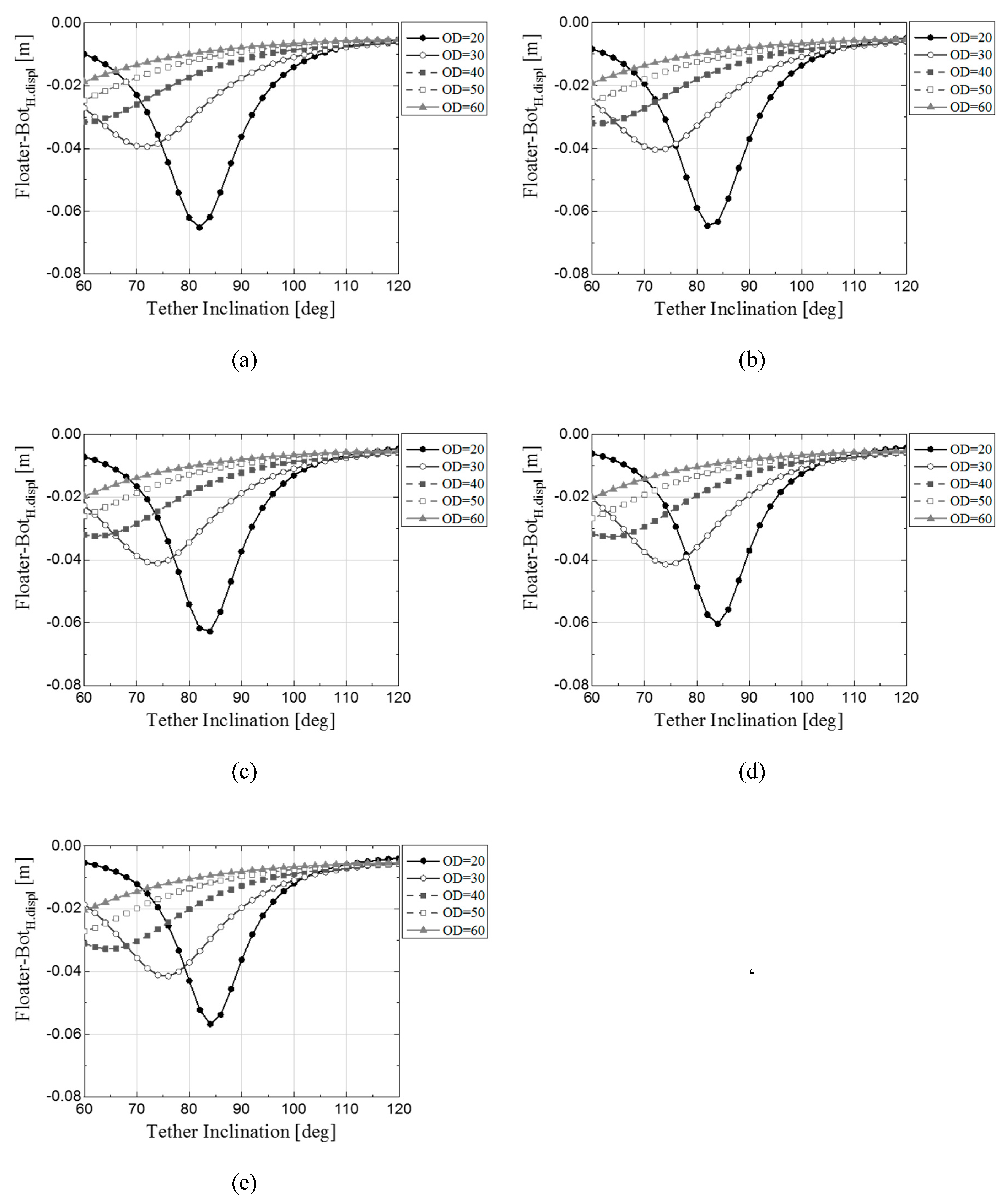
The measuring point of the displacement is shown in Figure 12. The horizontal displacement of the lower part of the floater according to the tether slope and the diameter–buoyancy ratio of the floater is shown in Figure 13. As with the top horizontal displacement of the tower, the horizontal displacement of the bottom of the floater was also found to be sensitively affected by the slope of a specific tether according to the floater OD. Under the horizontal displacement of the floater, a clear trend of behavior was confirmed. In the case of horizontal displacement of the floating body, the amount of initial tension acting on the tether also increased with the buoyancy, and thus, the amount of change caused by the buoyancy did not appear much at the position where the tether was attached.
3.2. Tower Displacement
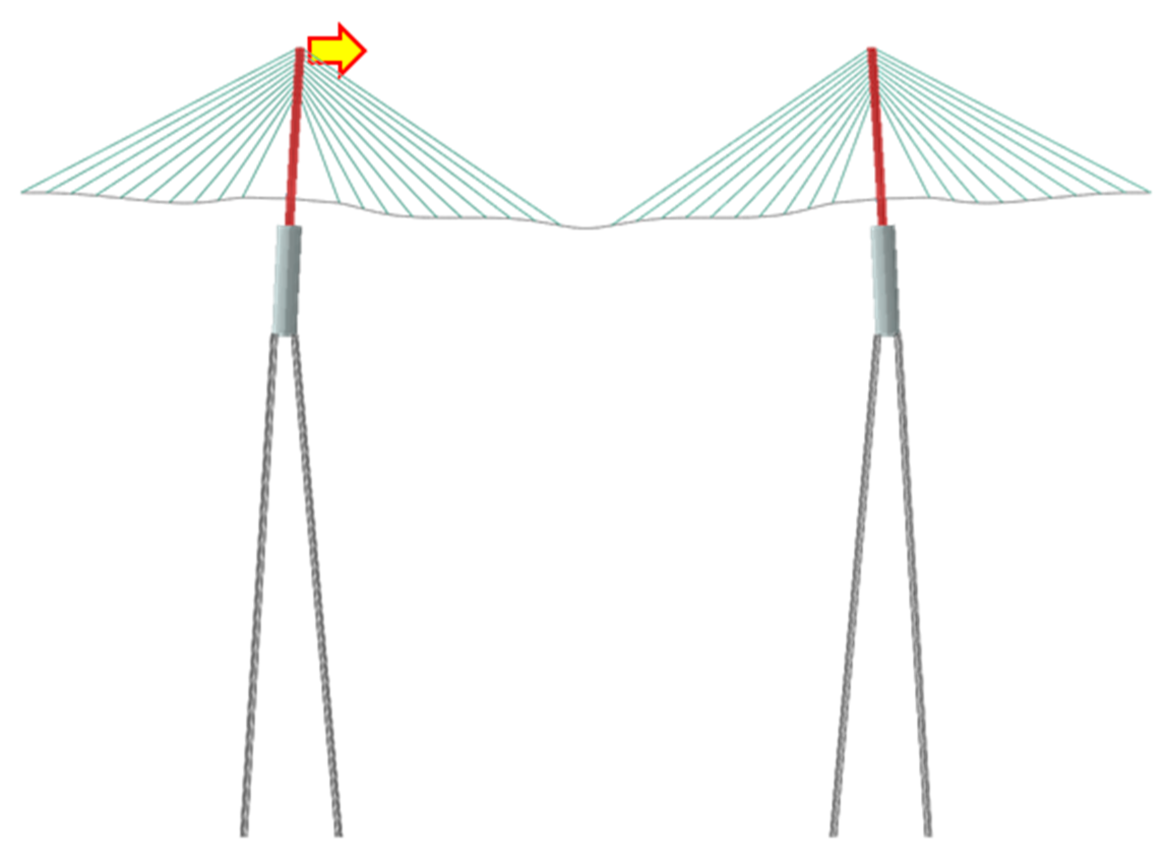
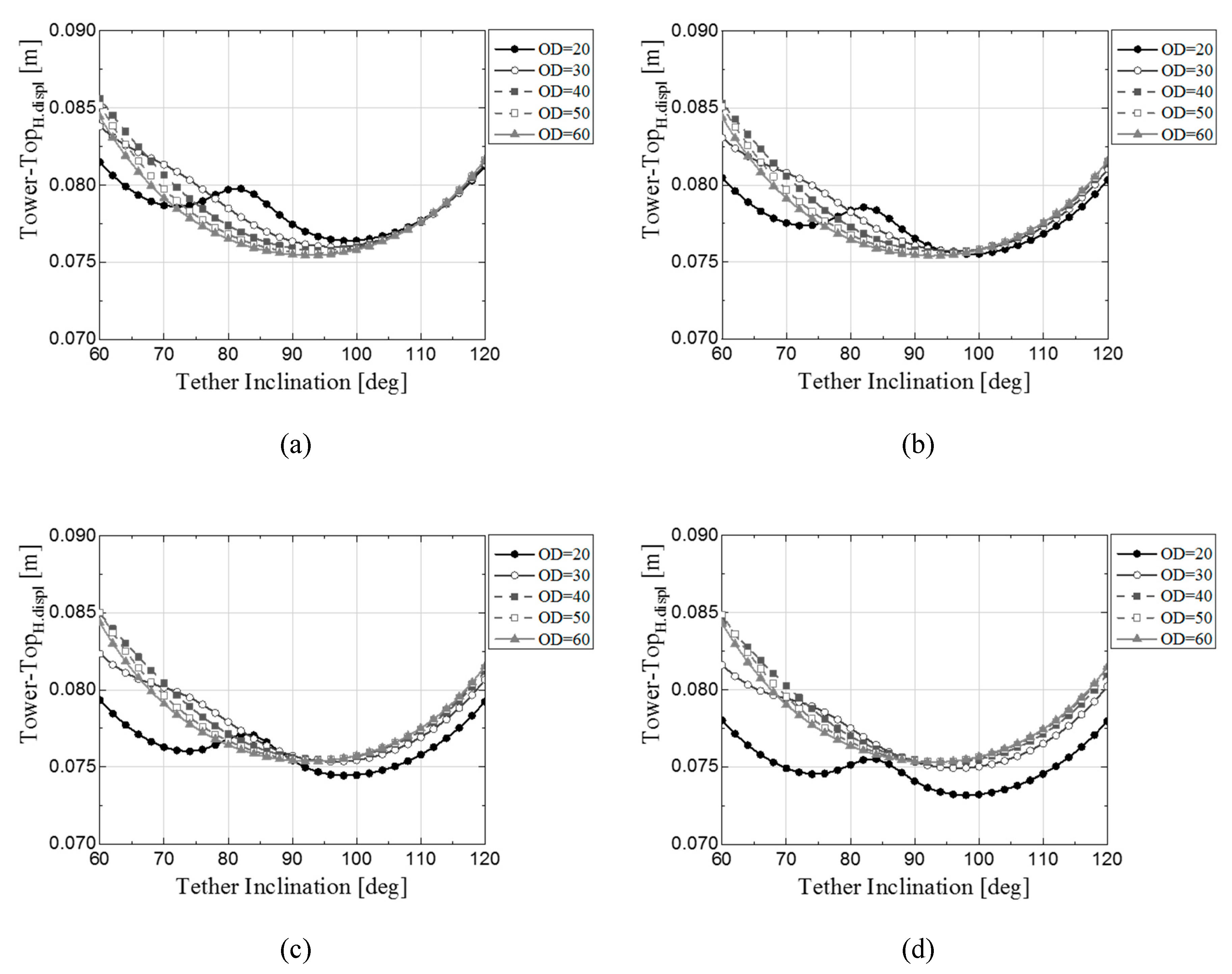
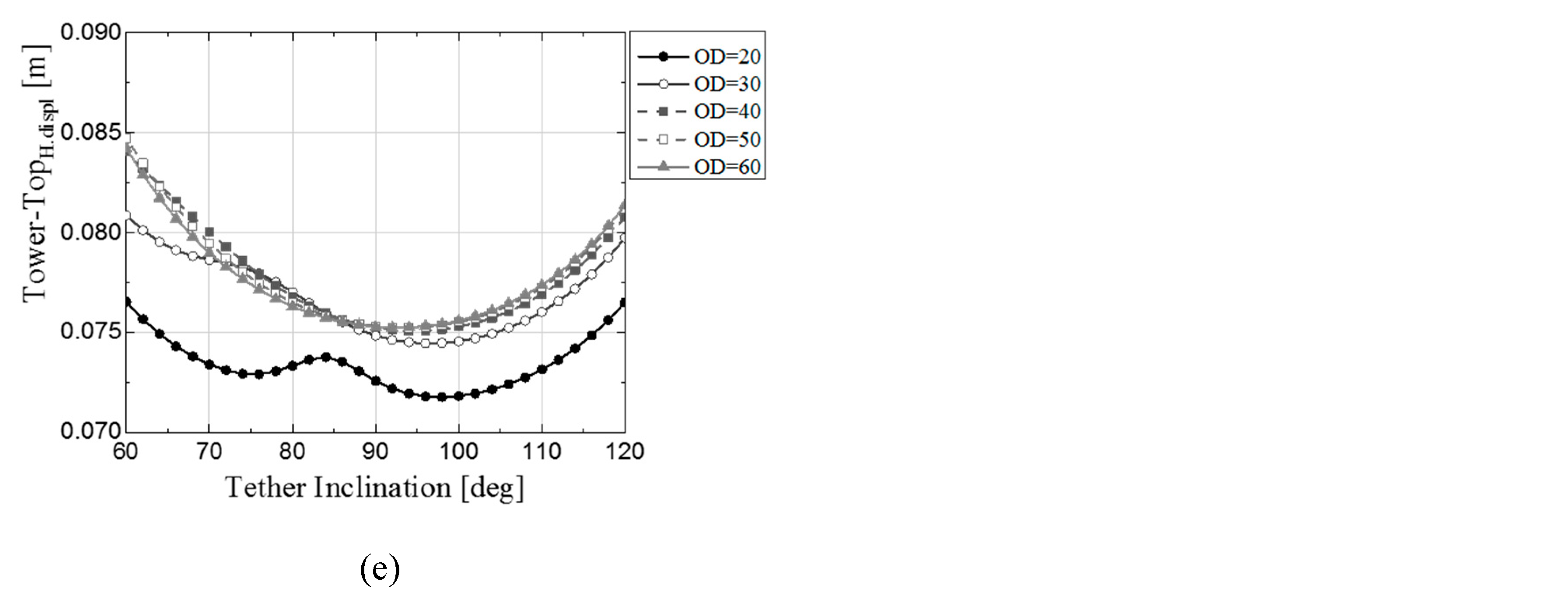
The horizontal displacement of the top of the tower depended on the tether slope, floater diameter, and buoyancy ratio. The measuring point of the displacement is shown in Figure 14. It was confirmed that, under the floating body ODs of 20 m and 30 m, the structure behaved sensitively at a particular slope of the tether arrangement. In addition, as buoyancy increased, the horizontal displacement tended to decrease at the abovementioned ODs, as shown in Figure 15.
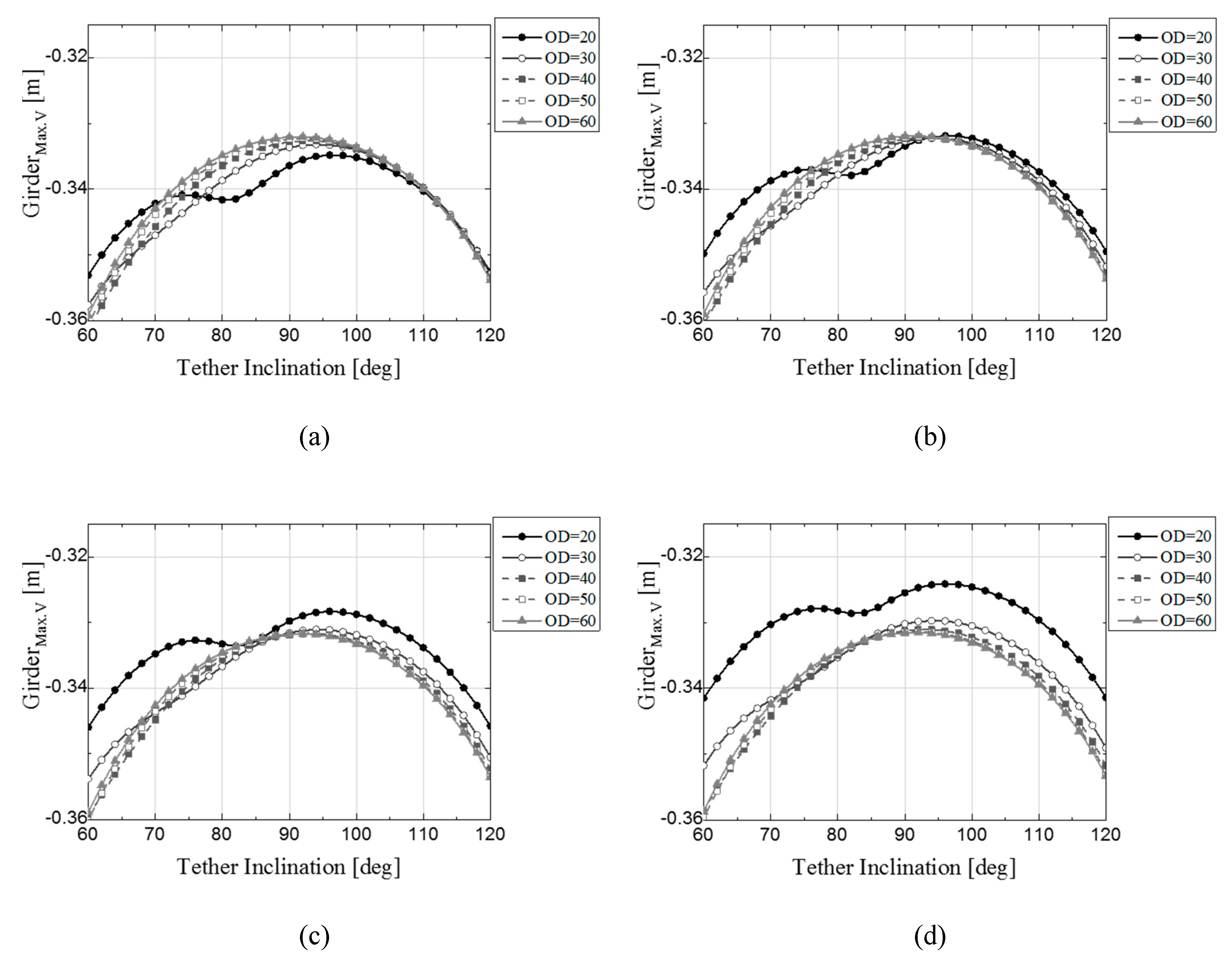
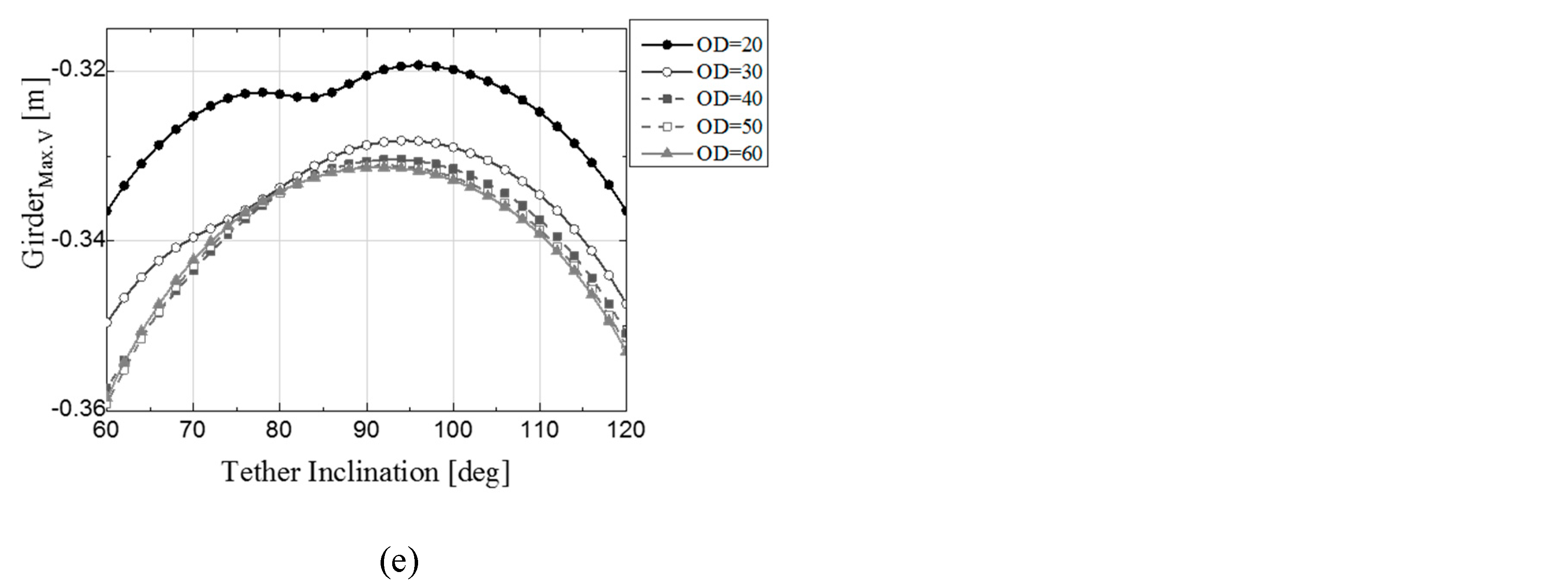
3.3. Girder Displacement
The maximum displacement of the girder center according to the tether slope and floater diameter–buoyancy ratio is shown in Figure 16. In the case of girder displacement, it was connected to the tower by the cable, and when the tower was supported by tethers, it was interactively affected by the vertical and horizontal displacements of the floater and tower. The unstable behavior of the girder displacement appeared at sensitive parts of the tether slopes in the horizontal displacement of the towers and floaters. In addition, at floater ODs of 20 m and 30 m, as the buoyancy increased, the horizontal and vertical displacements of the tower top decreased, which in turn decreased the maximum deflection of the girder.
3.4. Effect of Design Parameters on the Structural Behavior under Dead Loads
3.4.1. Effect of Tether Arrangement on the Static Behavior
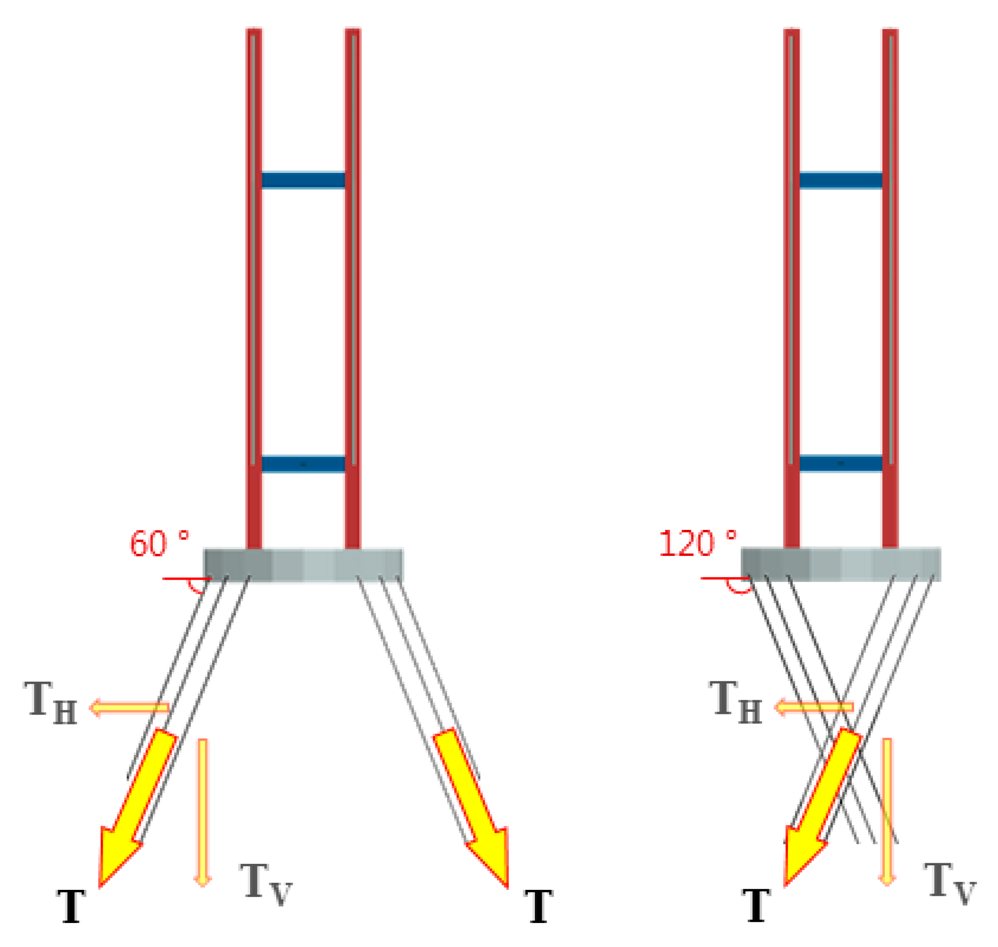
As the tether arrangement becomes inclined from the vertical arrangement, if the pre-tension of the tether is the same, the horizontal stiffness produced by it increases and the vertical stiffness decreases. As shown in Figure 17, the inclinations of 60° and 120° acted as the same support form in terms of the horizontal and vertical force components. However, although the magnitudes of the force component of the two forces were the same, the locations of the point of action of the tension and its intersection differed. The graph of the structural analysis results shows that the results were not symmetrical with respect to the vertical arrangement (90°) of the tether. The difference in the tension intersection is confirmed by the fact that the analysis results did not show symmetry.
As shown in Figure 13, Figure 15, and Figure 16, when the displacements of the floater, tower, and girder became unstable, the intersection of the tether tension direction gathered at the same specific point according to each floater diameter and tether slope.
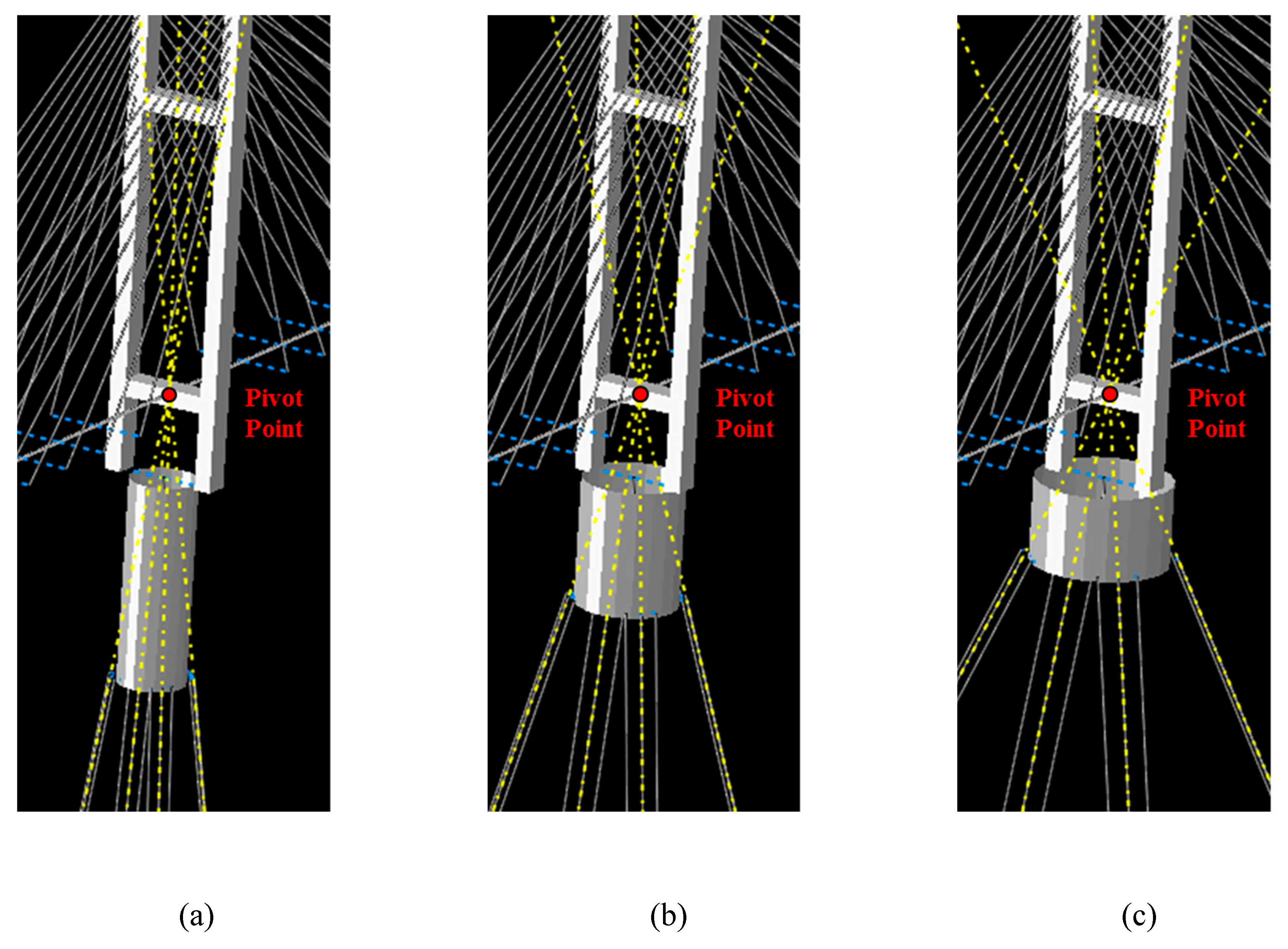
The displacements of the structure were sensitive when the intersection of the tether tension directions was gathered at the tower–girder intersection. As the tower and girder indicated a hinged connection, they were connected by the pivot point of the tower. When the tension direction of the tether was gathered at the tower’s pivot point, without a large displacement, the tension created by the tether could no longer resist the tower’s rotation. As a result, the tower exhibited unstable behavior with respect to rotation, and its instability affected the global behavior of floating cable-stayed bridges. Figure 18 shows an analytical model at BVR = 2.4, where the intersection of the tether’s tensile force is closest to the tower–girder connection, according to the floater diameter. Table 4 indicates the calculation result showing the slope when the intersection of the tether tension exactly matches the girder, according to the BVR and floater diameter. From the analysis results of Figure 13, Figure 15, and Figure 16, the tether slope at which the global behavior is sensitive is similar to each slope shown in Table 4. The phenomenon that did not appear at slopes over 90°, where the force components were the same, and appeared when the intersection of tensions coincided with that of the girder. The unstable behavior of the structure due to the tether slope appeared when the tether was no longer resistant to the tower rotation at certain slopes.
3.4.2. Effect of BVR and Floater OD on the Static Behavior
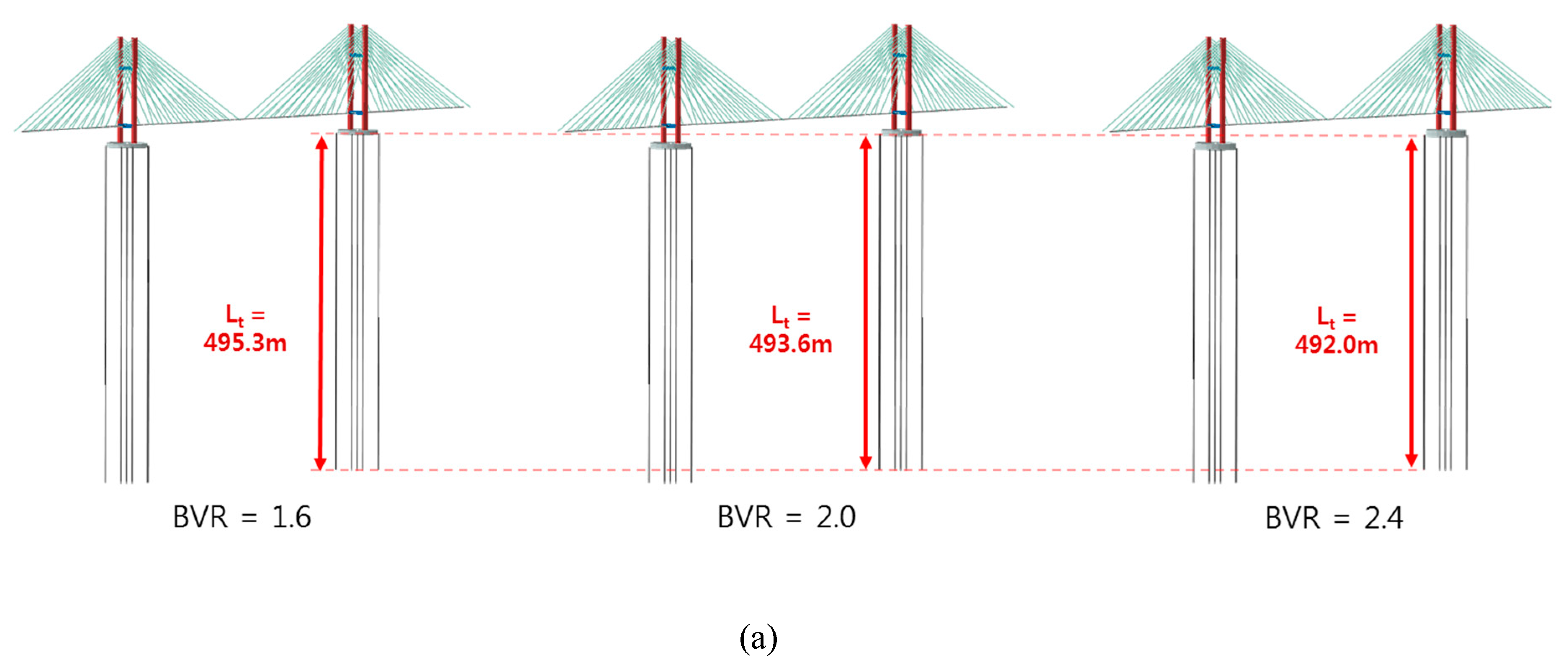
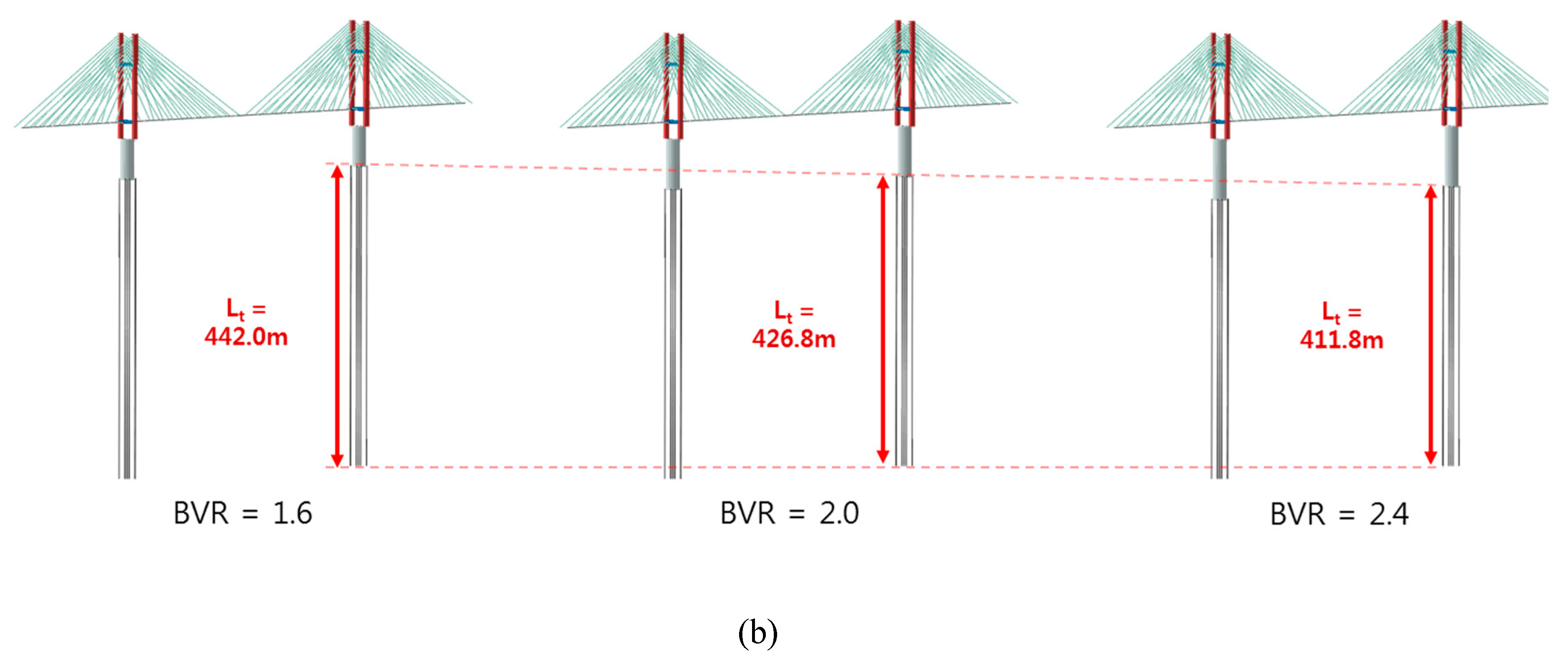
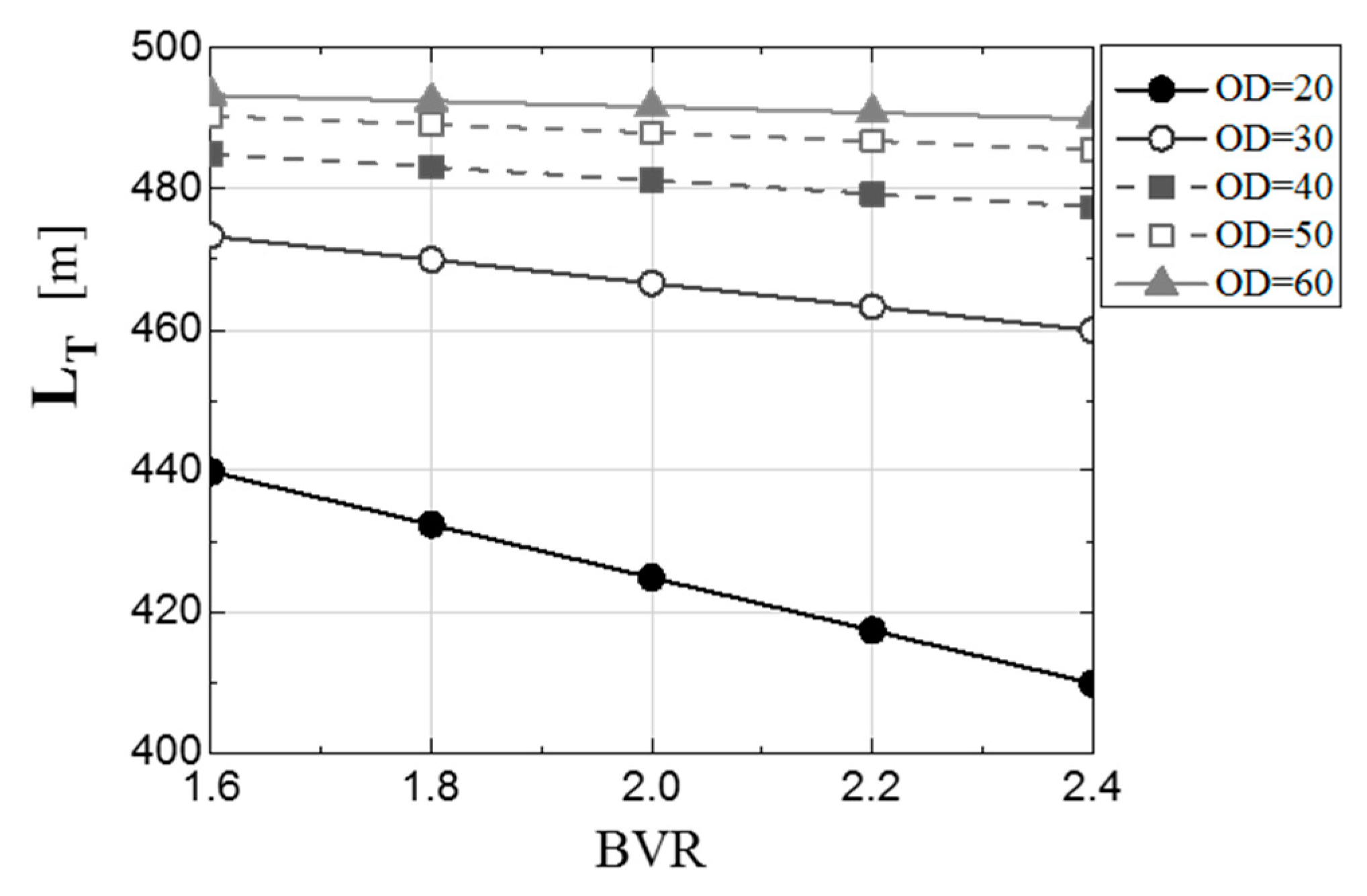
To exclude the rotational instability of the tower caused by the inclined arrangement of the tether, the behavior evaluation by BVR and OD was compared based on the vertical (90°) arrangement of the tethers. As the BVR increased, the required buoyancy, as well as the submerged volume of the floater, increased. As the floater had the same diameter, the buoyancy increased by adjusting the submerged depth and the length of tether attached to the bottom of the floater decreased with increasing BVR. Because the submerged floater depth varied significantly with the buoyancy ratio at a small OD, this tendency induced the largest change in tether length, as shown Figure 19 and Figure 20.
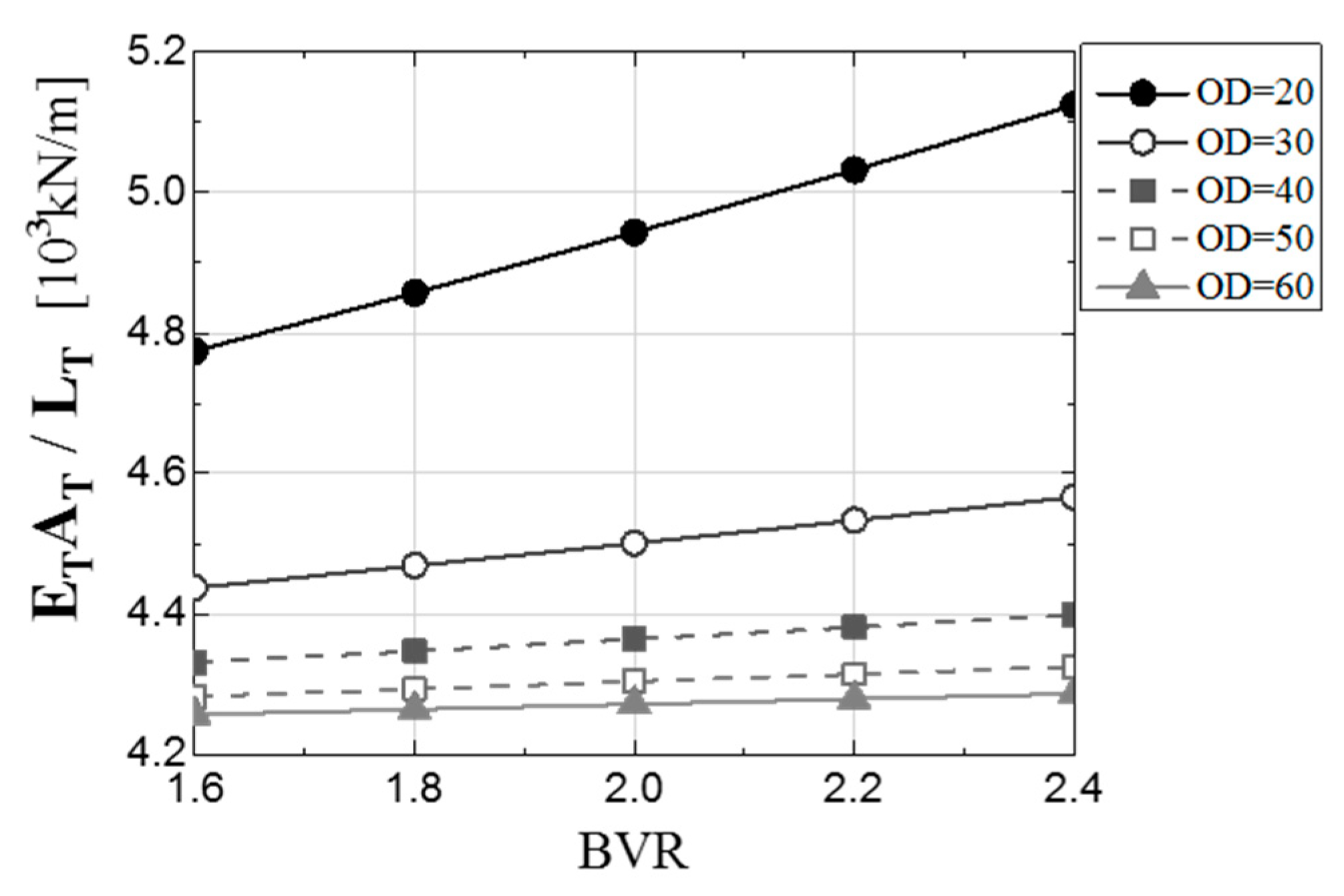
Although the rigidity of the tether was the same, the length decreased as the BVR increased, and the axial stiffness of the tether increased in inverse proportion to the length, as shown in Figure 21.
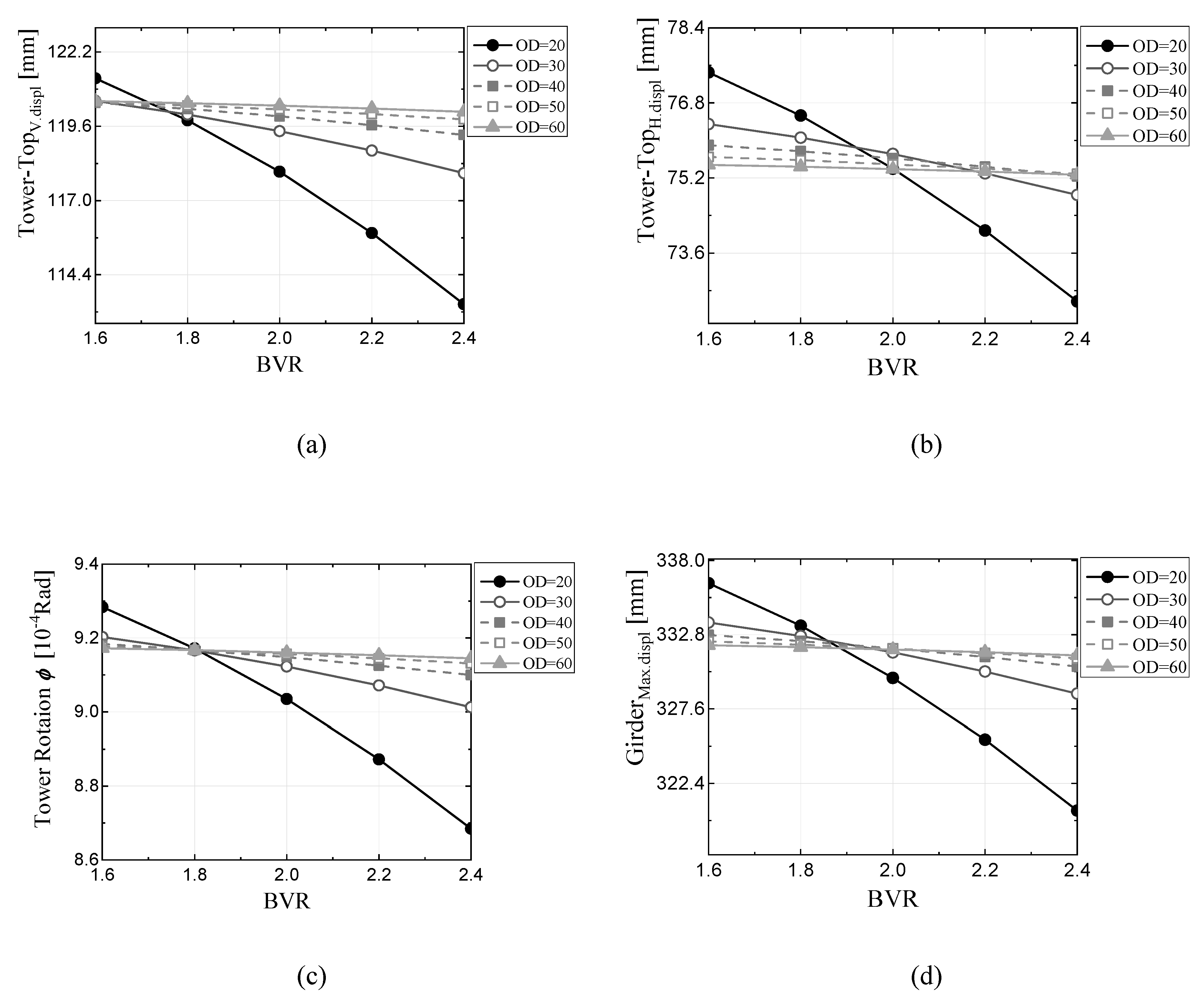
According to the result graph shown in Figure 22, the displacement of the tower and girder decreased as the BVR increased (increased axial stiffness of the tether). Figure 22(c) shows that, at BVR = 1.8, the effect of increase in the axial stiffness of the tether was greater than that of the increase in the floater OD, due to an increase in the rotational stiffness produced by the tether. At a small BVR (below 1.8), the vertical displacement of the girder was reduced due to the increase in OD, while at a larger BVR (over 2.0), it decreased with the OD due to an increase in the axial stiffness of the tether.
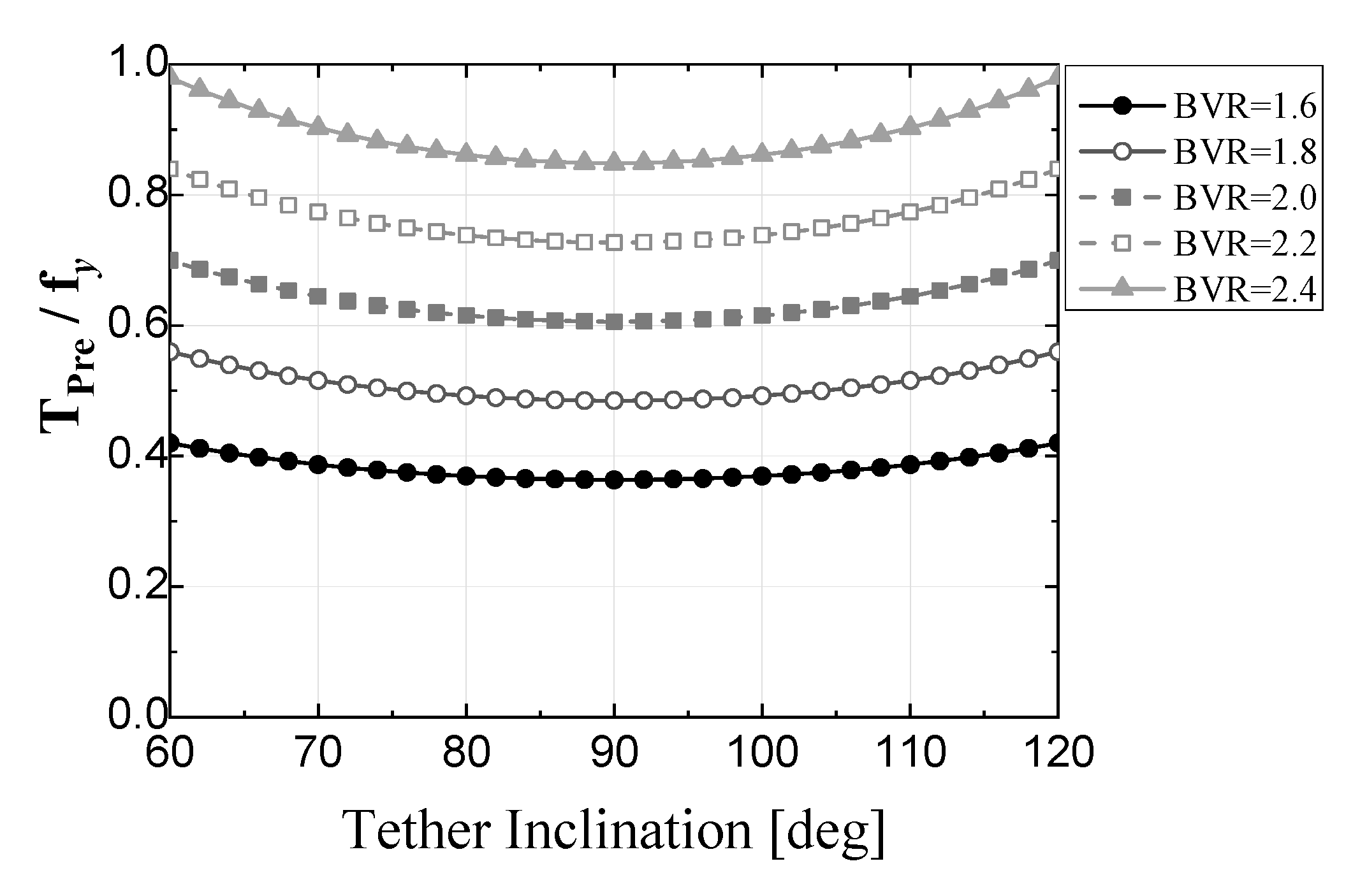
At a small BVR, an increase in OD is advantageous for an increase in the rotational stiffness, but at a large BVR, an increase in the axial stiffness due to a decrease in the tether length is more effective in increasing the rotational stiffness. However, an increase in BVR is accompanied by that in the pre-tension acting on the tether (especially in the case of an inclined arrangement), leading to a decrease in the safety margin of the tether as shown in Figure 23.
4. Conclusions
In this study, the geometrical static behaviors of cable-stayed bridges with floating towers were analyzed by conducting a geometric nonlinear finite-element analysis. The cable-stayed bridge with floating tower, even under the dead load only, confirmed the following behavior characteristics that did not appear in the fixed cable-stayed bridge.
- (1)
- The displacement of the structure sensitively responds to the specific inclination of the tether according to each OD. This tendency is particularly evident at the lower horizontal displacement of the floater, as well as in the displacement of the tower and girder. The difference between the tether’s obtuse and acute angle arrangements is the intersection of the tether’s tension, and it is confirmed that the structure’s behavior becomes more sensitive as the intersection approaches the connection between the main tower and the girder.
- (2)
- Without the large displacement of the cable-stayed bridge with a floating tower, the tether tensions will no longer resist the tower rotation when the intersection of the tether tensions coincides with the rotation center of the tower. Unlike the conventional floating sea-crossing structures, the cable-stayed bridge with a floating tower plays a very important role in securing stability against overturning of the structure because the center of gravity of the superstructure is located above the center of buoyancy. The exact center of rotation of the towers should be clearly interpreted and confirmed, and the design of the tether arrangement must be performed considering the intersection of tether tensions.
- (3)
- The larger the floater diameter, the lesser the change in the static behavior of the structure, according to the buoyancy ratio and tether slope. When the floater diameter is 60 m and the buoyancy ratio is 2.0, the sensitive behavior exhibited by the inclined tether will also appear at 44.4°, where the tether tension intersects the rotational center of the tower. On the other hand, if the floater diameter is small, the sensitive behavior of the structure occurs only with a very small inclination arrangement of the tether, and the overall displacement decreases as the BVR increases.
- (4)
- As the BVR increases, the floater depth of the same diameter increases, in order to create a larger buoyancy. The tether attached to the floater bottom becomes shorter at the same depth as the submerged depth of the floater increases. This decrease in tether length increases its axial stiffness. In addition, the smaller the floater diameter, the larger is the reduction in length and increase in axial stiffness. That is, as the BVR increases, the static behavior of the structure decreases due to an increase in the axial stiffness of the tether. However, a larger BVR leads to a larger required pre-tension of the tether (even if the tether is inclined, additional pre-tension is required).
- (5)
- The rotational stiffness produced by the tether is determined by the length of the rotating arm resulting from the floater diameter and the axial stiffness of the tether. In the analytical model of this study, until the BVR reaches 1.8, the larger the diameter of the floating body, the lesser is the rotational displacement of the tower. After BVR 2.0, the shorter the tether length, the larger is its axial stiffness and the smaller is the rotational displacement.
Author Contributions
Conceptualization, M.J., Y.-J.K., and S.K.; methodology, S.K.; structural analysis, M.J.; validation, M.J., and Y.L.; investigation, M.J., Y.L, D.W., and S.K.; resources, Y.-J.K.; data curation, M.J. and Y.L; writing—original draft preparation, M.J.; writing—review and editing, S.K.; visualization, M.J.; supervision, S.K.; project administration, S.K.; funding acquisition, S.K. All authors have read and agreed to the published version of the manuscript.
Funding
The research was funded by a Korea University Grant (K1923211).
Acknowledgments
Authors appreciate kind supports from Korea University.
Conflicts of Interest
The authors declare no conflict of interest.
References
- Won, D.; Seo, J.; Kim, S.; Park, W.-S. Hydrodynamic Behavior of Submerged Floating Tunnels with Suspension Cables and Towers under Irregular Waves. Appl. Sci. 2019, 9, 5494. [Google Scholar] [CrossRef] [Green Version]
- Won, D.; Kim, S. Feasibility Study of Submerged Floating Tunnels Moored by an Inclined Tendon System. Int. J. Steel Struct. 2018, 18, 1191–1199. [Google Scholar] [CrossRef]
- Kim, S.; Won, D.; Seo, J.; Jeong, W.-M.; Kang, Y.-J. Hydrodynamic Behavior of Submerged Floating Pipeline under Regular Waves. J. Pipeline Syst. Eng. Pract. 2020, 11, 04020017. [Google Scholar] [CrossRef]
- Ellevset, O. Norwegian coastal highway route E39-Status overview. In Proceedings of the Bridges Annual Conference, Oslo, Norway, 3–4 November 2014. [Google Scholar]
- Wan, L.; Jiang, D.Q.; Dai, J. Numerical Modelling and Dynamic Response Analysis of Curved Floating Bridges with a Small Rise-Span Ratio. J. Mar. Sci. Eng. 2020, 8, 467. [Google Scholar] [CrossRef]
- Cifuentes, C.; Kim, S.; Kim, M.; Park, W. Numerical simulation of the coupled dynamic response of a submerged floating tunnel with mooring lines in regular waves. Ocean Syst. Eng. 2015, 5, 109–123. [Google Scholar] [CrossRef]
- Kvåle, K.A.; Sigbjörnsson, R.; Øiseth, O. Modelling the stochastic dynamic behaviour of a pontoon bridge: A case study. Comput. Struct. 2016, 165, 123–135. [Google Scholar] [CrossRef]
- Shixiao, F.; Weicheng, C.; Xujun, C.; Cong, W. Hydroelastic analysis of a nonlinearly connected floating bridge subjected to moving loads. Mar. Struct. 2005, 18, 85–107. [Google Scholar] [CrossRef]
- Papinutti, M.; Bruer, A.; Marley, M.H.; Kvaleid, K.J.; Hatami, A.; Pathak, A.; Bhide, S. A frequency domain tool for investigation of wind response of TLP suspension bridges. In Proceedings of the IABSE Symposium 2017, Vancouver, BC, Canada, 19–23 September 2017; Engineering the Future: Vancouver, BC, Canada, 2017; pp. 198–205. [Google Scholar]
- Papinutti, M.; Aas-Jakobsen, K.; Kaasa, L.H.; Bruer, A.; Marley, M.H.; Veie, J.; Holtberget, S.H. Coupled Wind and Wave Load Analyses of Multi-span Suspension Bridge Supported by Floating Foundations. In Proceedings of the IABSE Symposium, Vancouver, BC, Canada, 19–23 September 2017; Engineering the Future: Vancouver, BC, Canada, 2017; pp. 2052–5039. [Google Scholar]
- Xu, Y.; Øiseth, O.; Moan, T.; Naess, A. Prediction of long-term extreme load effects due to wave and wind actions for cable-supported bridges with floating pylons. Eng. Struct. 2018, 172, 321–333. [Google Scholar] [CrossRef]
- Xu, Y.; Øiseth, O.; Moan, T. Time domain simulations of wind- and wave-induced load effects on a three-span suspension bridge with two floating pylons. Mar. Struct. 2018, 58, 434–452. [Google Scholar] [CrossRef] [Green Version]
- Kim, S.; Won, D.; Kang, J.S. Dynamic Behavior of Cable-stayed Bridges with Floating Towers under Waves. J. Korean Soc. Steel Constr. 2018, 30, 205–216. [Google Scholar] [CrossRef]
- Kim, S.; Won, D.H.; Jang, M.; Lee, Y.; Kang, Y.J. Short-term Fatigue Damage of the Tendons for Cable Supported Bridgeswith Floating Towers under the Severe Wave Condition. J. Korean Soc. Steel Constr. 2019, 31, 211–221. [Google Scholar] [CrossRef]
- Korea Road & Transportation Association. Korean Hightway Bridge Design Code; Korea Road & Transportation Association: Seoul, Korea, 2016. [Google Scholar]
- SIMULIA. ABAQUS/Standard V2018; Dassault Systems Simulia Corp; Simulia: Johnston, RI, USA, 2018. [Google Scholar]
- Irvine, H.M. Cable Structures; MIT Press: Cambridge, MA, USA, 1981; p. 259. [Google Scholar]
- Karoumi, R. Some modeling aspects in the nonlinear finite element analysis of cable supported bridges. Comput. Struct. 1999, 71, 397–412. [Google Scholar] [CrossRef]
- Wang, H.P.; Tseng, T.C.; Yang, C.G. Initial shape of cable-stayed bridges. Comput. Struct. 1993, 44, 1095–1106. [Google Scholar] [CrossRef]
- Kim, K.-S.; Lee, H.S. Analysis of target configurations under dead loads for cable-supported bridges. Comput. Struct. 2001, 79, 2681–2692. [Google Scholar] [CrossRef]
- Kim, S.; Won, D.; Kang, Y.J. Ultimate behavior of steel cable-stayed bridges-I. Rational ultimate analysis method. Int. J. Steel Struct. 2016, 16, 601–624. [Google Scholar] [CrossRef]
- Kim, S.; Won, D.; Kang, Y.J. Ultimate behavior of steel cable-stayed bridges-II. Parametric study. Int. J. Steel Struct. 2016, 16, 625–636. [Google Scholar] [CrossRef]
Figure 1.
The long-span bridge with floating tower.

Figure 2.
Global deformation shape (scale factor = 5). (a) Comparison of fixed and floating cable-stayed bridges without pre-tension (fixed: —, floating: —); (b) floating cable-stayed bridge (without pre-tension: —, with pre-tension: —).
Figure 2.
Global deformation shape (scale factor = 5). (a) Comparison of fixed and floating cable-stayed bridges without pre-tension (fixed: —, floating: —); (b) floating cable-stayed bridge (without pre-tension: —, with pre-tension: —).

Figure 3.
Initial member force method.

Figure 4.
Iteration results of initial shape analysis about each tether inclination. (a) Maximum vertical displacement of a girder; (b) displacement reduction by iterations.
Figure 4.
Iteration results of initial shape analysis about each tether inclination. (a) Maximum vertical displacement of a girder; (b) displacement reduction by iterations.

Figure 5.
Cable tension distribution.

Figure 6.
Fan-type analysis model.

Figure 7.
Analysis model. (a) Fan-type two-sided arrangement of cables; (b) cross section of tower; (c) cross section of girder; (d) tether attachment position.
Figure 7.
Analysis model. (a) Fan-type two-sided arrangement of cables; (b) cross section of tower; (c) cross section of girder; (d) tether attachment position.


Figure 8.
The floater and tethers in the heeled condition.

Figure 9.
Outer diameter (OD) of the floater with equal buoyancy: (a) OD = 20 m; (b) OD = 40 m; (c) OD = 60 m.
Figure 9.
Outer diameter (OD) of the floater with equal buoyancy: (a) OD = 20 m; (b) OD = 40 m; (c) OD = 60 m.

Figure 10.
Inclined arrangement of tethers: (a) 80°; (b) 90°; (c) 100°.

Figure 11.
Buoyancy vertical load ratio (BVR) parameters: (a) BVR = 1.6; (b) BVR = 2.0; (c) BVR = 2.4.
Figure 11.
Buoyancy vertical load ratio (BVR) parameters: (a) BVR = 1.6; (b) BVR = 2.0; (c) BVR = 2.4.

Figure 12.
Floater-Bot horizontal displacement; BVR = 2.4, OD = 20 m, 84 deg, Scale Factor = 100.

Figure 13.
Floater-Bot horizontal displacement: (a) BVR = 1.6; (b) BVR = 1.8; (c) BVR = 2.0; (d) BVR = 2.2; (e) BVR = 2.4.
Figure 13.
Floater-Bot horizontal displacement: (a) BVR = 1.6; (b) BVR = 1.8; (c) BVR = 2.0; (d) BVR = 2.2; (e) BVR = 2.4.

Figure 14.
Tower-top horizontal displacement; BVR = 2.4, OD = 20 m, 84 deg, scale factor = 100.

Figure 15.
Tower-top horizontal displacement: (a) BVR = 1.6; (b) BVR = 1.8; (c) BVR = 2.0; (d) BVR = 2.2; (e) BVR = 2.4.
Figure 15.
Tower-top horizontal displacement: (a) BVR = 1.6; (b) BVR = 1.8; (c) BVR = 2.0; (d) BVR = 2.2; (e) BVR = 2.4.


Figure 16.
Maximum vertical displacement of the girder: (a) BVR = 1.6; (b) BVR = 1.8; (c) BVR = 2.0; (d) BVR = 2.2; (e) BVR = 2.4.
Figure 16.
Maximum vertical displacement of the girder: (a) BVR = 1.6; (b) BVR = 1.8; (c) BVR = 2.0; (d) BVR = 2.2; (e) BVR = 2.4.


Figure 17.
Force component produced by tension of tether, OD = 60 m.

Figure 18.
Intersection of tether tension according to OD of the floater and tether inclined, at BVR = 2.4, in the analysis model: (a) OD = 20 m, 84°; (b) OD = 30 m, 74°; (c) OD = 40 m, 64°.
Figure 18.
Intersection of tether tension according to OD of the floater and tether inclined, at BVR = 2.4, in the analysis model: (a) OD = 20 m, 84°; (b) OD = 30 m, 74°; (c) OD = 40 m, 64°.

Figure 19.
Comparison of tether lengths: (a) OD = 60 m; (b) OD = 20 m.


Figure 20.
Length of tether by BVR.

Figure 21.
Axial stiffness of tether by BVR.

Figure 22.
Displacement and rotation by BVR and OD: (a) vertical displacement of the tower; (b) horizontal displacement of the tower; (c) rotational angle of the tower; (d) maximum displacement of the girder.
Figure 22.
Displacement and rotation by BVR and OD: (a) vertical displacement of the tower; (b) horizontal displacement of the tower; (c) rotational angle of the tower; (d) maximum displacement of the girder.

Figure 23.
Required pre-tension of the tether by inclined tethers.


Table 1.
Comparison of the rotational stiffnesses.
| OD [m] | Rotational Stiffness (kNm/rad) | |
|---|---|---|
| 12 Tethers | Change of the Buoyancy Center in the Heeled Condition | |
| 20.0 | 1.08 × 10⁶ | 1.97 × 10² |
| 30.0 | 2.21 × 10⁷ | 4.44 × 10² |
| 40.0 | 3.81 × 10⁷ | 7.90 × 10² |
| 50.0 | 5.87 × 10⁷ | 1.23 × 10³ |
| 60.0 | 8.40 × 10⁷ | 1.78 × 10³ |
Table 2.
Section properties.
| E (N/m2) | A (m2) | I (m4) | γ (kN/m3) | Compression | |
|---|---|---|---|---|---|
| Girder | 2.1 × 10¹¹ | 0.75 | 1.45 | 77.01 | Y |
| Tower | 2.1 × 10¹¹ | 0.37 | 3.14 | 77.01 | Y |
| Cross beam | 2.1 × 10¹¹ | 0.37 | 3.14 | 77.01 | Y |
| Floater | 2.1 × 10¹¹ | 2.51~7.54 | 125~3392 | 77.01 | Y |
| Cable | 2.1 × 10¹¹ | 0.01 | - | 77.01 | N |
| Tether | 2.1 × 10¹¹ | 0.0364 | - | 77.01 | N |
Table 3.
Considered parameters.
| BVR | OD | Inclined Arrangement of Tether |
|---|---|---|
| 1.6 | 20 m | 60° 62° |
| 1.8 | 30 m | 64° 66° |
| 2.0 | 40 m | ⋮ |
| 2.2 | 50 m | 114° 116° |
| 2.4 | 60 m | 118° 120° |
Table 4.
Inclination of tether where the intersection of tension exactly matches the girder.
| BVR | Floater | Tether | |
|---|---|---|---|
| OD [m] | Draft [m] | Inclination [deg] | |
| 1.6 | 20 | 60.13 | 81.8 |
| 30 | 26.73 | 71.1 | |
| 40 | 15.03 | 60.0 | |
| 50 | 9.62 | 50.4 | |
| 60 | 6.68 | 42.9 | |
| 1.8 | 20 | 67.65 | 82.5 |
| 30 | 30.07 | 72.2 | |
| 40 | 16.91 | 61.1 | |
| 50 | 10.82 | 51.4 | |
| 60 | 7.52 | 43.6 | |
| 2.0 | 20 | 75.16 | 83.0 |
| 30 | 33.41 | 73.2 | |
| 40 | 18.79 | 62.2 | |
| 50 | 12.03 | 52.4 | |
| 60 | 8.35 | 44.4 | |
| 2.2 | 20 | 82.68 | 83.5 |
| 30 | 36.75 | 74.1 | |
| 40 | 20.67 | 63.3 | |
| 50 | 13.23 | 53.3 | |
| 60 | 9.19 | 45.2 | |
| 2.4 | 20 | 90.20 | 84.0 |
| 30 | 40.09 | 74.9 | |
| 40 | 22.55 | 64.2 | |
| 50 | 14.43 | 54.2 | |
| 60 | 10.02 | 45.9 | |
Publisher’s Note: MDPI stays neutral with regard to jurisdictional claims in published maps and institutional affiliations. |
© 2020 by the authors. Licensee MDPI, Basel, Switzerland. This article is an open access article distributed under the terms and conditions of the Creative Commons Attribution (CC BY) license (http://creativecommons.org/licenses/by/4.0/).
Share and Cite
MDPI and ACS Style
Jang, M.; Lee, Y.; Won, D.; Kang, Y.-J.; Kim, S. Static Behaviors of a Long-span Cable-Stayed Bridge with a Floating Tower under Dead Loads. J. Mar. Sci. Eng. 2020, 8, 816. https://doi.org/10.3390/jmse8100816
AMA Style
Jang M, Lee Y, Won D, Kang Y-J, Kim S. Static Behaviors of a Long-span Cable-Stayed Bridge with a Floating Tower under Dead Loads. Journal of Marine Science and Engineering. 2020; 8(10):816. https://doi.org/10.3390/jmse8100816
Chicago/Turabian StyleJang, Minseo, Yunwoo Lee, Deokhee Won, Young-Jong Kang, and Seungjun Kim. 2020. "Static Behaviors of a Long-span Cable-Stayed Bridge with a Floating Tower under Dead Loads" Journal of Marine Science and Engineering 8, no. 10: 816. https://doi.org/10.3390/jmse8100816
Note that from the first issue of 2016, this journal uses article numbers instead of page numbers. See further details here.