


Abstract
SOLPS-ITER edge code analysis including drifts shows that optimization of divertor target shaping in a small angle slot (SAS) can strongly influence E× B drift particle fluxes, potentially improving divertor detachment for both toroidal field directions. This is enabled by directing recycling neutrals toward the separatrix from both the common flux region (CFR) and the private flux region (PFR) walls of the slot with a V-shape target in the slot (SAS-V), leading to two separate reinforcing effects, each individually involving positive feed-back: (a) increase of neutral recycling at the PFR wall of the slot due to—and causing—strong radial E× B ion flux from the CFR to the PFR; (b) decrease of E× B loss of ions out of the outer divertor into the inner divertor via the PFR due to reduction of the radial gradient of electron temperature at the outer target caused by the increased particle retention in the outer divertor. This circumvents the general problem for divertor operation with ion B ×∇B toward the X-point: E× B loss of particles from the outer divertor CFR plasma tends to keep it hot and attached. This work identifies a strong interaction between divertor geometry and drifts, a potentially important effect for optimizing advanced divertors for power exhaust in fusion reactors.
Export citation and abstract BibTeX RIS

Original content from this work may be used under the terms of the Creative Commons Attribution 3.0 license. Any further distribution of this work must maintain attribution to the author(s) and the title of the work, journal citation and DOI.
A major challenge facing the design and operation of a fusion reactor is to develop a robust divertor solution for adequate control of both heat flux and erosion, which requires satisfying the following requirements: divertor target heat load: q⊥ ≤ 10–15 MW m−2; electron temperature at the divertor target: Tet ≤ 5–10 eV across the divertor target to suppress net erosion, e.g. of a W divertor target with low-Z impurity seeding [1, 2]. The present ITER divertor design [3] aims to achieve highly dissipative, detached divertor conditions by operating at a high main plasma density, i.e. with the Greenwald density fraction, ne /nGW ∼ 1. Future steady-state fusion reactors will face increased challenges in the control of the boundary plasma consistent with efficient current drive, which favors relatively low density, and robust high fusion performance [4, 5].
Extensive efforts have been made in divertor optimization over the last three decades to enhance divertor energy dissipation by recycling neutrals [6–11]. Recently, a new small-angle slot divertor concept [12], also known as slot with advanced shaping (small angle slot (SAS)), has been developed on DIII-D to promote divertor detachment by leveraging the effect of a closed slot structure and appropriate target shaping to tailor the neutral distribution over the target surface. The original modeling with the two-dimensional fluid boundary code package SOLPS 5.0/B2-EIRENE, but without including cross-field drifts [13], showed that SAS can improve divertor detachment over other divertor configurations, including standard horizonal target configuration and more advanced ITER-like vertical target configuration, owing to the following key factors: (1) the slot structure reduces neutral leakage from both the private flux region (PFR) and the common flux region (CFR), i.e. the scrape-off layer (SOL); (2) appropriate target shaping to control the distribution of recycling neutrals to achieve cold plasma across the divertor target, in contrast to widely used vertical target configurations which tend to achieve partial detachment near the strike point with the plasma remaining hot in the far SOL. Recent experimental tests on DIII-D [14] showed that the SAS configuration can provide strong cooling of the plasma near the divertor target over a wider range of high confinement (H-mode) plasma conditions, as the original SOLPS5.0 modelling indicated. SOLPS5.1 modeling of the first detachment experiment in SAS showed a significant reduction in Te at the strike point than that in a matched open divertor for a given separatrix density [15]. However, these benefits are only realized for ion B×∇B away from the X-point, while the effects are much smaller for the opposite field direction. This suggests that, at least for DIII-D size devices, cross-field drifts have comparable effects to divertor geometry on the divertor plasma, and must be considered for the optimization of advanced divertors.
Tests of SAS in DIII-D showed that moving the strike point close to the inboard target of the slot can improve divertor plasma cooling, relative to the other strike point locations for the favorable Bt direction. This indicates that the reflection of recycling neutrals by the slant target in the PFR might reduce the E× B drift flow to the inner divertor on the high-field side (HFS) through the PFR, better confine particles and thus improve plasma cooling in the slot on the low field side. However, the divertor plasma remains relatively hot throughout the SOL, due to the leakage of neutrals from the divertor through the SOL region. This experimental observation motivated incorporating a V-shape target into an improved SAS design to move both inboard and outboard slant targets very close together to form a so called 'V-shape' target surrounding the strike point, i.e. SAS-V, to directly reflect and direct recycling neutrals toward the strike point from both CFR and PFR sides [16]. This improved SAS-V configuration would enable better confinement of particles in the slot, raising ne and reducing Te , for the favorable Bt direction, thus potentially promoting divertor detachment for both Bt directions. It should be noted that SAS-V differs from the earlier proposed V-shape target configuration for JT60-SA [17] and SlimCS-DEMO [18], which involves plasma contact on just the CFR side of the outer V-shaped target.
In this letter we report the first SOLPS-ITER modeling of such a SAS-V configuration using SOLPS-ITER including drifts. The present effort follows and builds on the ongoing program of SAS divertor development and optimization on DIII-D, and takes a step forward in the investigation. The aim here is to further optimize slot geometry to mitigate the undesirable impact of drifts for ion B×∇B toward the X-point, in particular for between-ELM H-mode plasmas and plasmas without ELMs achieved using ELM control methods. It is worth noting that this is a general problem for tokamaks, which usually operate with ion B×∇B toward the X-point, i.e. for the 'favorable' Bt direction with regard to the lower power threshold for access to H-mode [19].
Figure 1 shows a sketch of a SAS configuration similar to that being currently tested experimentally on DIII-D, and the new SAS-V divertor configuration, along with the SOLPS-ITER simulation meshes. The SOLPS-ITER code package [20], the latest coupled version of the multi-fluid transport code B2.5 [13] and the kinetic neutral transport code EIRENE [21], is used with E× B drifts switched on. The simulations were carried out for a deuterium (D) plasma. The core-edge boundary is at R–Rsep = − 2.02 cm, at the outside midplane (OMP). Pedge = 1.0 MW. For consistency we have adopted the same, typical transport coefficients as used in the previous SOLPS modeling of H-mode plasmas. The specified diffusivity profiles at the OMP were chosen to provide an H-mode type of edge pedestal (R–Rsep = − 1.0 cm to 1.0 cm) with the cross-field particle and heat diffusivities: D⊥ = 0.1 m2/s, χ⊥ = 0.2 m2 s−1, while in the core (R–Rsep = − 2.02 cm to − 1.0 cm) and SOL (R–Rsep = 1.0 cm to 1.14 cm) regions: D⊥ = 1.0 m2 s−1, χ⊥ = 1.7 m2 s−1, for both electron and ions. The diffusivities in the divertor are increased by a factor of 10 to account for enhanced divertor transport, based on the indications from recent divertor experiments and simulations on DIII-D [22, 23]. The particle recycling coefficient is set to 1, except at the surface provided for pumping, where it is 0.95, corresponding to a realistic pumping speed of 17.0 m3 s−1. The plasma facing components (PFCs), including the divertor target and the main chamber wall, are assumed to be carbon (C) and C impurity is included in the model. The source of C impurity is the sputtering of the C PFCs due to chemical and physical sputtering between ELMs. This is a common practice in divertor detachment studies of H-mode plasmas on DIII-D e.g. [22–24],. For the typical H-mode discharges in DIII-D, the ELM frequency increases from about 40 Hz at low density to 100 Hz at high density near detachment. The divertor parameters between ELMs were carefully assessed by applying appropriate time-windows to the measurements; the resulting data are found to be nearly constant temporally, including carbon production, as indicated by CIII emissions, and are therefore taken to represent inter-ELM divertor conditions. Here we have taken the same approach in the simulations as in previous modeling work of H-mode plasmas. Detailed study of carbon source and transport are beyond the scope of this work. The chemical sputtering yield is fixed at Ychem
= 0.01, while the physical sputtering yield Yphys
is calculated using the modified Roth–Bohdansky formula [25]. Electrons and ions for each ionization state (D+
, C+, C2+, C3+, C4+, C5+, C6+) are simulated by the B2.5 code, while the neutrals (D, C and D2) are tracked by the EIRENE code. B2.5 solves a set of continuity and parallel momentum equations for each ion species, the current continuity and energy equations for the ion temperature Ti and electron temperature Te. EIRENE solves a set of linear transport equations for the neutral atoms and molecules including ionization, charge exchange, dissociation, elastic collisions and volume recombination processes. For the simulations without drifts, the standard Bohm sheath boundary conditions were applied at the target surface, i.e. V//t
= cs
, while it becomes V//t
+ VE ×B

 = cs
when activating E× B drifts [26], where V//t
is the plasma flow speed in the parallel direction at the target, and
= cs
when activating E× B drifts [26], where V//t
is the plasma flow speed in the parallel direction at the target, and  is the plasma isothermal sound speed. In this work, we focus on the impact of E× B drifts, while ignoring the ion diamagnetic drift, which has a secondary effect.
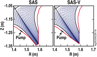
Figure 1. Sketch of a SAS configuration similar to that being tested on DIII-D and an improved SAS-V configuration with a V-shaped target encompassing the strike point. Also shown are the meshes and pump location for SOLPS-ITER simulations.
Download figure:
Standard image High-resolution imageWe use a simplified SAS geometry as a 'reference' configuration in the SOLPS-ITER modeling, to capture the essential features of SAS, i.e. a narrow slot with small angle targets, but the exact geometry differs in detail from that employed in DIII-D [14]. Furthermore, the heating power used for the simulations presented in this paper is lower than what was actually used for the tests of SAS in DIII-D, to facilitate convergence and accelerate the modeling process. Nevertheless, SOLPS-ITER modeling of the simplified SAS has reproduced the trend of the dependence of divertor behaviour on Bt directions. It is important to note that in these simulations we changed the direction of Bt only, while keeping all the other input parameters the same, thus isolating and focusing on the specific effect of drifts. Drifts have been clearly identified by the recent tests of SAS on DIII-D as playing as critical a role as divertor geometry, i.e. closure.
The SOLPS-ITER simulations including E× B drifts show that the SAS-V configuration can retain the beneficial effect of the SAS geometry, while mitigating the adverse effect of the E× B drift for favorable Bt
direction, which occurs in SAS, as shown in figure 2. As can be seen, for ion B×∇B away from the X-point, i.e. unfavorable Bt
, SAS can achieve cold divertor plasma conditions with the electron temperature at the outer strike point (OSP), Te,OSP
 5 eV for very low electron densities at the outer midplane separatrix, ne,sep
. Compared with the simulation without E× B drifts, it appears that SAS benefits from both geometric effects and drifts, improving divertor detachment over the full range of densities. In contrast, for ion B×∇B toward the X-point, i.e. favorable Bt
, the divertor plasma remains hot, not achieving Te,OSP
5 eV for very low electron densities at the outer midplane separatrix, ne,sep
. Compared with the simulation without E× B drifts, it appears that SAS benefits from both geometric effects and drifts, improving divertor detachment over the full range of densities. In contrast, for ion B×∇B toward the X-point, i.e. favorable Bt
, the divertor plasma remains hot, not achieving Te,OSP
 5 eV until much higher ne,sep
, and Te,OSP is significantly higher than for E× B drifts turned off. Note that, in this case, the SAS experiments achieved similar results to other divertor configurations in DIII-D, showing that the anticipated geometric effect was largely offset by the drifts. The present simulations qualitatively reproduce the experimental results obtained with the SAS divertor in DIII-D [14]. By contrast, SAS-V enables achievement of dissipative divertor conditions with Te,OSP
5 eV until much higher ne,sep
, and Te,OSP is significantly higher than for E× B drifts turned off. Note that, in this case, the SAS experiments achieved similar results to other divertor configurations in DIII-D, showing that the anticipated geometric effect was largely offset by the drifts. The present simulations qualitatively reproduce the experimental results obtained with the SAS divertor in DIII-D [14]. By contrast, SAS-V enables achievement of dissipative divertor conditions with Te,OSP
 5 eV at very low ne,sep
independent of field direction, as shown in figure 2.
5 eV at very low ne,sep
independent of field direction, as shown in figure 2.
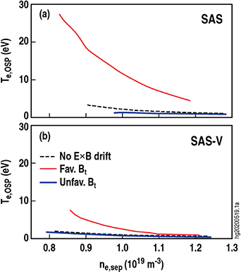
Figure 2. Comparison of (a) SAS and (b) SAS-V: electron temperature at the target at the outer strike point, Te,OSP , as a function of electron density at the outer midplane separatrix, ne,sep , for the SOLPS-ITER simulations without including the E × B drift (black dash), and with the E × B drift for favourable Bt direction (red) and unfavorable (blue) Bt.
Download figure:
Standard image High-resolution imageDirecting recycling neutrals (D and D2) toward the strike point from both CFR and PFR sides of the slot not only further reduces Te at the strike point, but also leads to the flattening of the radial gradient of Te across the target. Figure 3 compares the radial profiles of neutral density, nD +D2 , electron density, ne , electron temperature, Te , as well as parallel heat flux, q//, at the divertor target for SAS and SAS-V, for favorable and unfavorable Bt directions, at the same upstream separatrix density, ne,sep ∼ 1 × 10¹⁹ m−3. The results from SOLPS-ITER modelling without E× B drifts are also shown to illustrate the 'pure' geometric effects of SAS and SAS-V configurations. As can be seen, SAS-V causes a strong concentration of neutrals at the strike point by directing recycling neutrals from both CFR and PFR sides of the slot, as manifested by a sharply peaked distribution of nD +D2 at the OSP, with nD +D2,OSP ∼ 5 times higher than that in SAS. Correspondingly, both Te and q//are further reduced across the divertor target in SAS-V compared with SAS, for all modeling cases, with or without including E× B drifts. A strong correlation between neutral density and the corresponding Tet at divertor targets was discovered in the SOLPS code analysis for the original SAS physics design [27]. This indicates a causal relationship: the new SAS-V configuration can better confine recycling neutrals than the SAS configuration, thus further enhancing divertor cooling, in particular, in the near-SOL, i.e. near the OSP, due to the strong concentration of recycling neutrals at the strike point.
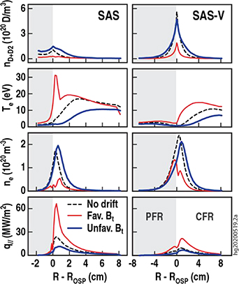
Figure 3. Radial profiles of neutral (D and D2) density, nD +D2, electron temperature, Te , electron density, ne ,, as well as parallel heat flux, q//, at the divertor target in SAS and SAS-V for ne,sep ∼ 1 × 10¹⁹ m−3, calculated by SOLPS including E× B drifts for favorable (red) and unfavorable (blue) Bt. Simulations without E× B drift (black dash) are also shown to illustrate the geometric effect for the two different configurations.
Download figure:
Standard image High-resolution imageWhen the E× B drift is switched on, SOLPS-ITER finds that for unfavorable Bt , the E× B drift pushes ions out of the outer PFR into the outer CFR for both SAS and SAS-V, densifying and cooling the plasma in the CFR, thus driving the divertor plasma into detachment. For favorable Bt , in SAS, the E× B drift pushes ions into the outer PFR from the outer CFR, rarefying and heating the plasma in the CFR, thus driving the divertor plasma away from detachment. In SAS-V, the E× B drift also pushes ions into the outer PFR from the outer CFR, but the strike point is still detached in SAS-V. What is the explanation for this major difference with SAS? We consider the answer next.
The SOLPS-ITER modeling shows that the reflection of recycling neutrals from the PFR slant target in SAS-V increases ne
in the PFR, thus leading to a local flattening of the radial gradient of Te, as shown in figure 3. This reduces the radial electric field Er and thus the associated poloidal E× B drift within the outer PFR, thus 'plugging the drain' of particles out of the outer PFR into the inner PFR for favorable Bt
—a critical feature of SAS-V. To illustrate this, figure 4 compares the target profile of Te
, plasma potential  and
and  in SAS and SAS-V for favorable Bt
, at ne,sep
∼ 1 × 10¹⁹m−3.
in SAS and SAS-V for favorable Bt
, at ne,sep
∼ 1 × 10¹⁹m−3.  was calculated by the SOLPS-ITER code which included the effect of j||
on the sheath potential and on Ohm's Law. As shown in figure 4, the radial profile of Vp
largely follows the radial variation of Te
. As expected for a typical divertor plasmas, a strong Er
is present in the outer PFR of SAS due to the sharp radial gradient of Te
near the separatrix, which is directed radially inward, thus driving an ion poloidal E× B flow out of the outer PFR into the inner PFR on the HFS. However, Er
∼ 0 in the outer PFR of SAS-V, largely eliminating the poloidal E× B flow there. As a result, SAS-V exhibits a strong reduction in the ion poloidal E× B flow from the outer to inner divertor via the PFR
over the full range of densities
for favorable Bt
. as shown in figure 5. The poloidal E× B drift via the PFR tends to drive the outer divertor away from detachment, and thus, SAS-V provides a way to circumvent this general problem of divertor operation.
was calculated by the SOLPS-ITER code which included the effect of j||
on the sheath potential and on Ohm's Law. As shown in figure 4, the radial profile of Vp
largely follows the radial variation of Te
. As expected for a typical divertor plasmas, a strong Er
is present in the outer PFR of SAS due to the sharp radial gradient of Te
near the separatrix, which is directed radially inward, thus driving an ion poloidal E× B flow out of the outer PFR into the inner PFR on the HFS. However, Er
∼ 0 in the outer PFR of SAS-V, largely eliminating the poloidal E× B flow there. As a result, SAS-V exhibits a strong reduction in the ion poloidal E× B flow from the outer to inner divertor via the PFR
over the full range of densities
for favorable Bt
. as shown in figure 5. The poloidal E× B drift via the PFR tends to drive the outer divertor away from detachment, and thus, SAS-V provides a way to circumvent this general problem of divertor operation.

Figure 4. Radial profiles of electron temperature, Te , plasma potential, Vp , and radial electric field, Er , at the divertor target in SAS and SAS-V, respectively, calculated by SOLPS-ITER including E × B drifts for favorable Bt , at ne,sep ∼ 1 × 10¹⁹ m−3.
Download figure:
Standard image High-resolution image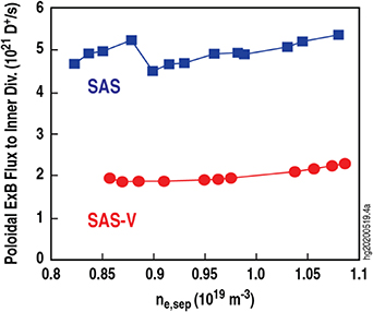
Figure 5. Comparison of total ion poloidal E × B flux from the outer to inner divertor via the PFR in SAS and SAS-V, calculated by SOLPS-ITER including E × B drifts for favorable Bt.
Download figure:
Standard image High-resolution imageFurthermore, the reflection of recycling neutrals by the slant target in PFR, coupled with the decrease in the loss of ions due to the poloidal E× B drift via the PFR, creates a positive feedback loop for particle fluxes, further promoting divertor cooling:
- In SAS-V, the slant surface in the outer PFR directs a large neutral recycling flux,
 , into the outer CFR; this increases ne
in the CFR, , which in turn increases the radial ion E× B flux from the CFR into the PFR since ; this then increases the recycling flux coming off the PFR slant surface, thereby increasing the neutral flux into the outer CFR; etc. Thus a positive feedback loop is created for particles in the oute divertor driving ne
up and thus Te
down, leading to detachment.
, into the outer CFR; this increases ne
in the CFR, , which in turn increases the radial ion E× B flux from the CFR into the PFR since ; this then increases the recycling flux coming off the PFR slant surface, thereby increasing the neutral flux into the outer CFR; etc. Thus a positive feedback loop is created for particles in the oute divertor driving ne
up and thus Te
down, leading to detachment.


- The density feedback is made stronger in SAS-V because the ion poloidal E× B loss to the HFS is small, as discussed above, i.e. the reflection of recycling neutrals from the slant PFR target flattens the radial gradient of Te at the PFR target, reducing the radial electric field Er in the PFR and the resulting ion poloidal E× B loss to the PFR on the HFS.
Table 1. Heat flux and radiative power (kW) for SAS and SAS-V, as calculated by SOLPS-ITER for the different E× B directions, along with the case without drifts.
| No drift | Fav. Bt | Unfav. Bt | |||
|---|---|---|---|---|---|
| SAS | Out div. entrance | 472 | 632 | 381 | |
| Out target | 186 | 391 | 86 | ||
| Out div. radiation | 286 | 241 | 295 | ||
| Inner div. entrance | 366 | 161 | 446 | ||
| Inner target | 194 | 35 | 295 | ||
| Inner div. radiation | 172 | 126 | 151 | ||
| No drift | Fav. Bt | Unfav. Bt | |||
| SAS -V | Out div. entrance | 450 | 574 | 369 | |
| Out target | 98 | 244 | 53 | ||
| Out div. radiation | 352 | 330 | 316 | ||
| Inner div. entrance | 391 | 265 | 459 | ||
| Inner target | 187 | 64 | 286 | ||
| Inner div. radiation | 204 | 201 | 173 | ||
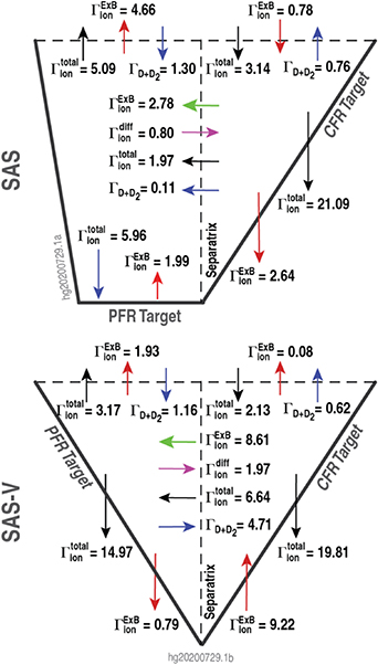
Detailed particle analysis of the SOLPS-ITER numerical results, as shown in figure 6, finds that the strong ion-neutral recycling at the PFR slant target in SAS-V is sustained by a large radial ion E× B drift ( = 8.6 × 10²¹ D+/s) from outer CFR into outer PFR across the separatrix. As a result, a large number of recycling neutrals ( = 4.7 × 10²¹ D s−1) are directed back into the CFR by the slant target in the PFR. Further, although the radial ion E× B drift from the CFR into the PFR is much stronger in SAS-V (
 = 8.6 × 10²¹ D+/s) than SAS (
 = 2.8 × 10²¹ D+/s), the ion loss from the outer PFR to the inner PFR in SAS-V (
 = 1.9 × 10²¹ D+/s) is much smaller than in SAS (
 = 5.4 × 10²¹ D+/s).
Figure 6. Ion and neutral fluxes (unit: 1.0 × 10²¹/s), including poloidal and radial E× B drift fluxes  and
and  , total poloidal and radial particle fluxes
  , radial diffusion flux
  , poloidal and radial neutral fluxes,
  , at the different target surfaces (PFR target, CFR target, Separatrix, as well as the divertor SOL entrance and PFR exit for SAS (top) and SAS-V (bottom). For ne,sep
∼ 1 × 10¹⁹ m−3.
, at the different target surfaces (PFR target, CFR target, Separatrix, as well as the divertor SOL entrance and PFR exit for SAS (top) and SAS-V (bottom). For ne,sep
∼ 1 × 10¹⁹ m−3.
Download figure:
Standard image High-resolution image
Detailed power balance analysis, as presented in table 1, shows that in both SAS and SAS-V a significantly higher power flux enters the outer divertor for favorable Bt , due to convection by the poloidal E× B flow into the divertor, than occurs for unfavorable Bt . In particular, it may be noted that, for favorable Bt , a significant reduction in q//and Te in SAS-V relative to SAS, as shown in figure 3, can be attributed to the following:
- The ion flux from the outer divertor into the inner divertor is reduced, as discussed above. This results in higher ne and lower Te , thus enhancing radiative losses in SAS-V (330 kW) relative to SAS (241 kW).
- In addition, the heat flux from the outer SOL into the slot is lower in SAS-V (574 kW) than in SAS (632 kW), which correlates with the reduced ion flux at the divertor entrance in SAS-V relative to SAS, as shown in figure 6, for favorable Bt .
In addition, as shown in table 1, SAS-V reduces the in-out divertor asymmetry in target power loading, i.e. the ratio of outer to inner target power loading is 3.81 in SAS-V, while it is 11.17 in SAS for favorable Bt . This points to a potentially useful divertor optimization direction for simultaneous control of detachment in both inner and outer divertors.
SOLPS-ITER modeling shows that the 'SAS-V effects' do not vary significantly when varying the location of the strike point along either side of the V-shape target within ∼ 1.5 cm of the corner of the V. Te,OSP
remains  10 eV and qperp,OSP
varies by a factor 2 provided the strike point is placed within 1.5 cm of the corner of the V.
10 eV and qperp,OSP
varies by a factor 2 provided the strike point is placed within 1.5 cm of the corner of the V.
In summary, SOLPS-ITER modelling including cross-field drifts has led to a promising discovery that improving target shaping to make a V-shaped target in SAS, i.e. SAS-V, can provide an effective way to manipulate the E× B drifts, leveraging the neutral recycling benefits of the SAS geometry to improve divertor detachment for both Bt directions. The new SAS-V configuration provides a strong concentrating effect of recycling neutrals toward the separatrix from both PFR and CFR sides of the outer divertor slot, further improving plasma cooling at the strike point relative to SAS. In addition, the reflection of recycling neutrals from the slant target in the PFR of SAS-V locally flattens the radial gradient of Te , reducing Er and the resulting poloidal E× B drift within the PFR, reducing the drain of ions from the outer divertor to the inner divertor. This acts synergistically with enhanced neutral recycling in the PFR, which causes a strong radial E× B drift from the CFR, in a positive feed-back loop for particles that results in cooling of the outer divertor.
It is not clear at this time how SAS effects will scale to larger tokamaks. On the one hand, it seems likely that larger, more powerful tokamaks will need divertors with larger volumes in order to be able to achieve the needed larger volumetric power dissipation, and therefore if the beneficial SAS effects are only significant in small volume divertors, SAS would not be relevant to such devices. On the other hand, it may be that provided that the far end of the divertor—i.e. the tip region of the slot—is on a small scale comparable to the size of SAS in DIII-D—that such a tip region SAS will act as a seed for precipitating detachment of the entire divertor volume and at a lower upstream plasma density than would occur otherwise. Recent SOLPS modeling for the divertor upgrade on KSTAR has in fact shown what appears to be such a seed-action effect [28].
Acknowledgments
The authors thank A.W. Leonard and D.M. Thomas for fruitful discussions. This work was supported by National Natural Science Foundation of China under Grant No. 11805057, National Key R&D Program of China No. 2018YFE0301101, and CNNC Elite Project under Grant No. 2019JZYF-01. The views and opinions expressed herein do not necessarily reflect those of the ITER Organization.