Advanced Biological Imaging for Intracellular Micromanipulation: Methods and Applications


1
State Key Laboratory for Manufacturing Systems Engineering and the International Joint Laboratory for Micro/Nano Manufacturing and Measurement Technologies, School of Mechanical Engineering, Xi’an Jiaotong University, Xi’an 710049, China
2
Department of Biomedical Engineering, City University of Hong Kong, Hong Kong SAR 999077, China
*
Author to whom correspondence should be addressed.
Appl. Sci. 2020, 10(20), 7308; https://doi.org/10.3390/app10207308
Submission received: 23 July 2020
/
Revised: 2 October 2020
/
Accepted: 5 October 2020
/
Published: 19 October 2020
(This article belongs to the Special Issue Advanced Intelligent Imaging Technology Ⅱ)
Abstract
:Intracellular micromanipulation assisted by robotic systems has valuable applications in biomedical research, such as genetic diagnosis and genome-editing tasks. However, current studies suffer from a low success rate and a large operation damage because of insufficient information on the operation information of targeted specimens. The complexity of the intracellular environment causes difficulties in visualizing manipulation tools and specimens. This review summarizes and analyzes the current development of advanced biological imaging sampling and computational processing methods in intracellular micromanipulation applications. It also discusses the related limitations and future extension, providing an important reference about this field.
1. Introduction
Intracellular organelles and molecules governing the liveness [1,2], dynamics [3,4], organizations [5,6], and functionalization [7,8] at cellular, multicellular, and tissue levels have attracted considerable interests from the field of biomedical research. Intracellular manipulation, measurement, and other surgical operations were conducted to unveil underlying mysteries inside cells [9]. For example, intracellular physical and chemical properties, such as Young’s modulus [10], viscosity [11], pressure [12], pH [13], and temperature [14], were measured to study biological processes and biomedical reactions in living cells. Some tracking macromolecules were delivered inside mammalian cells for the exploration of intracellular mechanisms, such as the entry of cytoplasmic molecules into primary cilia [15] and the release of spliced mRNAs from nuclear speckle domains [16]. Furthermore, genome-editing tasks have attracted research interest, particularly those that involve the transfer of DNA [17,18] and RNA molecules [19,20] to different cell types for cell transfection.
Although many intracellular manipulation techniques have been proposed, traditional clinical operations still depend on well-trained operators to fulfill various tasks [21]. In practice, operators laterally align manipulation tools with targeted specimens, manually adjust the relative height positions between manipulation tools and targeted specimens, and then initiate a given operation. Fatigue- and experience-induced failures always occur and result in low operation success rates and large damage, thus degrading the performance of intracellular manipulation [22,23]. Generally, intracellular objects are fragile [24,25] and usually have irregular shapes [26,27], distribution [28,29], and small sizes [30,31]. For example, mitochondria in mammalian animals are usually less than 2 μm and randomly distribute among the cytoplasm [32]. An inappropriate operation position not only leads to operation failure but also largely damages the targeted cells and even kills them. Therefore, the acquired position should be precisely manipulated through computational imaging during intracellular operations.
The complexity of intracellular environments and culture media inevitably causes difficulties in localizing operation positions [33,34,35]. The identification of targeted biological specimens is easily disturbed by unavoidable surroundings, such as counterpart cells and auxiliary manipulation tools, in an imaging field. Importantly, the morphological characteristics of most organelles are similar to those of their intracellular neighbors; as such, they become undistinguishable under optical observation [36]. Optical observation should be carried out several times to ensure that the imaging plane contains the target organelles because of the random distribution [37]. Meanwhile, most organelles have an irregular shape, so their appropriate operation position should be selected through comprehensive considerations [38]. Moreover, imaging blurs and noises during an optical observation deteriorate the imaging performance and make the organelles boundary unclear [39]. Apart from the automation demand of existing intracellular micromanipulation systems, two main challenges are encountered in current studies: how to obtain the sampled images of targeted intracellular specimens with high resolution and contrast and how to precisely extract operation information from the sampled images for a successful intracellular micromanipulation. The first challenge can be overcome with emerging advanced imaging technologies. With the help of some start-of-the-art imaging instruments and post-computation procedures, high-quality, real-time images during manipulation can be obtained. For the second challenge, many intelligent image computational processing methods have been proposed to restore the sampled images, analyze the targeted specimens, and provide precise visual feedback. Thus, the success rates of intracellular manipulation tasks can be improved, and operation damage can be reduced.
Reviews on biological imaging and computational processing methods in intracellular micromanipulation applications are rarely reported. In this review, advanced imaging technologies are described in terms of methods and applications in intracellular micromanipulation. First, sampling methods for deriving high-quality images are summarized in terms of imaging principles. Second, the intelligent computational image processing methods of the sampled images in different intracellular micromanipulation tasks are discussed and analyzed. Third, the limitations and drawbacks of each method are also explored. Lastly, conclusions and future outlook are presented. This systematic summary of this field can provide valuable references for academic and industrial fields.
2. Image Sampling Methods
Imaging sampling is essential for a successful intracellular micromanipulation through which the recognition, localization, tracking, reconstruction, motion, and orientation control of target specimens and manipulation tools heavily rely on the quality of sampled images. In other words, image sampling methods must be selected on the basis of several aspects, such as the size, morphology, distribution of specimens, imaging resolution, sampling speed and accessibility of the adopted instruments as well as their integration capability with other manipulation tools. For example, computer tomography (CT) and magnetic resonance imaging (MRI) are widely used in the visualization of bones, tissues, and organs, but they are unsuitable for imaging small-scaled specimens, such as cells and organelles [40,41].
This section mainly focuses on advanced biological imaging technologies at a cellular or subcellular level, such as commercially available state-of-the-art microscopes, including confocal fluorescence microscope (CFM), two-photon fluorescence microscope (TPFM), light sheet fluorescence microscope (LSFM), lab-built photoacoustic microscope (PAM), traditional wide-field fluorescence microscope (WFFM), advanced structured illumination microscope (SIM), and stimulated emission depletion microscope (STEDM) with a super-resolution imaging ability.
2.1. State-of-the-Art Microscopes
2.1.1. Confocal Fluorescence Microscope (CFM)
CFM has become a routine imaging tool in biological and biomedical sciences. The basic concept of confocal microscopes was first proposed in a previous study [42]. In brief, a pinhole aperture placed in front of a microscope photodetector can focus illuminated light on specimens, thereby rejecting most out-of-focus blurs during observation, as shown in Figure 1a. As commercially available instruments, CFM is widely adopted in imaging living cells, intracellular organelles, and components [43]. HeLa cells and porous CaCO3 particles were recorded with the aid of a CFM, which revealed the number of internalized vaterite particles and their crystalline structures [44], as shown in Figure 1b. The actin cytoskeleton architecture of Leukemia cell lines, Jurkat, and K562 cells were fully observed with a CFM to probe the underlying F-actin remodeling mechanism [45]. With the ability to control the imaging depth of a field and reducing background blurs away from the focal plane, CFMs can be used to measure the 3D structure of specimens. Polystyrene beads were delivered into human hepatocellular carcinoma (HCC) cells and verified with a 3D measurement from CFM [46], as shown in Figure 1c. In Figure 1d, the CFM 3D reconstruction crosses the dashed red line after microinjection for 15 s [47]. The spatial resolution of CFMs is restricted above 200 nm because of the diffraction limit of optical microscopes [48]. Research efforts have been devoted to improving the CFM resolution beyond the diffraction limit. A pinhole displacement method has been proposed to increase the contrast up to 80% with a diffraction-limited resolution of 250 nm [49]. The light intensity profile of Bessel beams follows Bessel function of different orders. This intensity distribution gives it a tighter focal spot than that of classic Gaussian beams, and its use in CFM can lead to a resolution enhancement of up to 20%. A CFM using Bessel–Gauss beams improved lateral resolution to 219 nm [50]. Furthermore, a fluorescence emission difference method illuminating specimens with a solid beam and a donut beam has been established. The final measured image was the subtraction of the acquired solid image and the donut one, and its lateral resolution was 210 nm, which was much higher than that of a conventional CFM [51]. In a resolution-doubling method, a point detector was replaced with an imaging detector via a recording algorithm, and the resolution of CFM can be increased to 162 nm [52]. With these methods, minor intracellular components such as actin filaments, microtubes, and proteins can be optically discriminated in CFM observations. However, CFM has the disadvantages of slow scanning speed [53] and high-intensity light [54], which may lead to short fluorescence lifetime and phototoxicity in living cells [55]. Therefore, the imaging time should be strictly controlled during CFM operation.
2.1.2. Two-Photon Fluorescence Microscope (TPFM)
TPFM principle is based on two-photon absorption and excitation phenomena, that is, the combined energy of two quasi-simultaneously absorbed photons is sufficient to match the energy gap between the ground and excited states [56]. The typical structure of a TPFM is illustrated in Figure 1e. With the reduction of photo-bleaching effect, TPFM has become a powerful instrument for long-term measurement [57]. For example, TPFM can be used to monitor the movement of transferred T-cells in mice for 48 h [58], as shown in Figure 1f. TPFM is not susceptible with interferences to fluorescence concentration and light sources. TPFM can be used to accurately detect fluorescent probes to track dynamic changes of hydrogen peroxide (H2O2) and adenosine triphosphate (ATP) in neurons [59]. In addition, TPFM can perform tomography to measure specimens at different optical depths. A TPFM-based rapid bacteria localization platform was proposed. This technique produced z-stack images to distinguish the intracellular and extracellular bacteria [60]. However, TPFM is mainly limited by the low imaging speed (about 0.5 Hz), and it take tens of minutes to obtain a high-resolution image stack for the traditional TPEM [61]. Recently, an advanced TPFM with a high sampling speed of 2.7 kHz has been developed using a multilfocus compressive sensing method and a digital micromirror device [62]. Besides, the spatiotemporal resolution of TPFM is relatively low, which is theoretically 500 nm laterally and 1 µm axially; it also follows the diffraction limitation [63]. Other studies have proposed a fast high-resolution miniaturized two-photon microscope (FHIRM-TPM) with a lateral resolution of 640 nm and an axial resolution of 3.35 µm [64], and a photomultiplier TPFM with a lateral resolution of 550 nm [65]. The measured lateral resolutions of a TPFM with a double-wavelength meta-surface object lens at light wavelengths of 820 and 605 nm are 930 and 680 nm, respectively [66]. For TPFM, the visualization of biological objects smaller than hundreds of nanometers in size seems challenging. However, TPFM, which benefits from high-energy photons, can drive the electronic excitation of deep fluorescent molecules and is suitable for deep tissue imaging [67]. Specifically, TPFM has attracted extensive interest in studies of the structure and function of the mammalian brain in vivo [68]. Last but not least, research should note the high purchase costs of TPFM, which are normally more expensive than others [69].
2.1.3. Light Sheet Fluorescence Microscope (LSFM)
LSFM is another instrument with a long-term measurement capability. A light sheet generated from a thin laser sampling beam is focused only on a portion of specimens, and fluorescence is then collected perpendicularly from the illumination axis [70], as shown in Figure 1g. The highly efficient excitation and collection scheme ensure that the phototoxic and photobleaching effects of LSFM are minimized compared with those of CFM and TPFM [71]. Specifically, exposure light energy was found to be 5600 and 106 times less than that of CFM and TPFM, respectively [72]. Therefore, LSFM is suitable for such applications requiring long-term measurement and careful exposure. Morphology changes of Drosophila embryos at different biological stages, such as germ band retraction, segment formation, and dorsal closure, were imaged with a LSFM [73]. Cardiomyocytes were imaged based on a customized LSFM for up to 1.5 days to investigate the holistic cell behaviors sculpting the four-chambered mammalian heart [74]. It should be noted that sampled images of LSFM are invulnerable to out-of-focus blurs, and they can exhibit more detailed features than normal wide-field microscopes [75]. Figure 1h shows the mitochondria visualization of HeLa cells labeled with the mitochondrial import receptor subunit TOM-20 by using a LSFM [76]. The image demonstrates a better contrast for LSFM than for wide-field illumination. The lateral resolution of LSFM is regulated primarily by the numerical aperture of the detection objective, while the axial resolution is additionally determined by the thickness of the light sheet [77]. Specifically, LSFM has a comparable lateral resolution as CFM. A single-objective LSFM with a resolution about 300 nm was proposed, which was based on the concept that combining objective with a coverslip-walled immersion chamber. Parallel recording of 16 cell lines and their cellular responses to drug treatment was conducted with this instrument [78]. Utilizing a LSFM with a scheme of two orthogonal detection and illumination objectives, the neural wiring during Caenorhabditis elegans brain development was imaged with a lateral resolution of 330 nm [79]. However, the axial resolution of LSFM is not as high as CFM, which is typically not better than 1 µm [72,80,81,82]. It is worthwhile to note that the complicated sample preparation is a problem for LSFM, because its orthogonal configuration hinders standard Petri dishes and multi-well plates for sample preservation [83]. In such a narrow space, the integration of LSFM with other manipulation tools is a huge challenge. Therefore, its applicability in intracellular micromanipulation is greatly limited.
2.2. Photoacoustic Microscope (PAM)
Photoacoustic imaging is inspired by the photoacoustic effect converting optical energy to measurable pressure waves [84]. This effect is initiated when specimens are irradiated with a modulated laser source, resulting in thermoelastic expansion and photoacoustic wave formation corresponding to the geometric characters of specimens [85]. Figure 2a shows the two main configurations of a photoacoustic microscope (PAM) in terms of imaging modes. One is the optical resolution (OR) mode in which the focused laser light is illuminated on specimens. The optical region of an OR-PAM is restricted, but its lateral resolution is improved. The other one is the acoustic resolution (AR) mode that adopts uniform illumination. The unfocused light enables deeper penetration but yields lower resolution [86].
Photoacoustic imaging technology is suitable for deep depth imaging, and because acoustic waves can transmit across soft tissues and skins, high-resolution imaging can be achieved at depths far exceeding the optical diffusion limit. In fact, photoacoustic imaging technology has been widely adopted for navigating microrobots in vivo. The migration of capsule micromotors was controlled to move to the targeted region in the intestines under the guidance of photoacoustic imaging [87], as shown in Figure 2b. PAM also has the advantages of label-free imaging and out-of-focus blur suppression, and has become an ideal technology for non-toxic biological imaging. Many subcellular practices have been imaged with enhanced contrast. This instrument can achieve a high lateral resolution of 250 nm. Figure 2c illustrates the sampled images of lipids, proteins, and nucleic acids in fibroblast cells by using an ultraviolet-localized mid-infrared PAM [88]. However, it lacks an optical sectioning capability. Theoretically, the axial resolution of PAM is controlled with the bandwidth of a photoacoustic signal and the central frequency of an ultrasonic transducer [89]. Studies have been performed to improve the axial resolution of PAM without losing its lateral accuracy. For instance, a Grueneisen relaxation photoacoustic microscope (GR-PAM) delivering two identical laser pulses has been proposed [90], where the axial resolution can be improved to 2.3 µm, and the lateral resolution was 410 nm. Figure 2d illustrates the optically sampled images of red blood cells at three different depths and their 3D reconstruction model. Another study has developed an isometric PAM based on a transparent micro-ring resonator ultrasonic detector, whose axial resolution was 2.12 µm [91]. In addition, an axial resolution improvement method has been established on the basis of configuration modification [92]. Figure 2e shows the dual-view PAM and sampled images of a mouse brain slice. Two split lasers are focused onto the specimens, and photoacoustic waves are collected with the ultrasonic transducer. This design can improve the axial resolution to 1.8 µm. Generally, due to its relative low axial resolution, PAM is more frequently to measure specimen profiles in 2D sampled planes instead of 3D space. Besides, PAM has several other limitations that hinder its applications in biological imaging. First, the sampling speed of PAM is low. There is a trade-off between resolution and sampling speed, that is, it takes several minutes to measure an area of 1 m × 1 m2 with an acceptable optical resolution using using OR-PAM [93]. Second, PAM requires complex light configurations, and there are almost no commercial tools available, which limits the accessibility of researchers who do not have expertise in this field. Finally, the potential damage from deposited laser energy is another issue that should be avoided in high-resolution imaging [94,95].
2.3. Wide-Field Fluorescence Microscope (WFFM)
With low purchase expenses and high accessibility [96], WFFM is popular in biological imaging. Figure 3a shows the WFFM observations of a burr-like porous spherical microrobot loaded with MC3T3-E1 fibroblasts, and the microrobot movement inside the yolk of a zebrafish embryo was measured for automation control [97]. Similar to CFM, WFFM suffer from a diffraction barrier. The resolution of WFFM can be expressed as (lateral) and (axial) [98], where λ is the wavelength of the emission light, and NA is the numerical aperture of the objective lens. Even for a WFFM with a high-NA objective lens, its resolution hardly reaches 230 nm laterally and 800 nm axially because the visible light wavelength varies from 390 to 780 nm [99]. During WFFM operation, the whole specimens are illuminated with emission light, and sampled images contain in-plane features, out-of-focus blurs projected from adjoined depths, and noises, which undoubtedly deteriorate the imaging quality, especially for depths that are far from the focused plane [100]. Such optical behavior can be modeled as a convolution process between point spread functions (PSFs) and the measured specimen [101]. To restore the sampled images of WFFM, many methods have been proposed on the basis of deconvolution algorithms that numerically invert blur processes, such as the Landweber method [102], Tikhonov–Miller gradient descent method [103], and Richardson–Lucy maximum likelihood method [104,105]. Figure 3b shows an unfocused sampled image of Caenorhabditis elegans and deconvoluted images with different deconvolution methods [106]. The processed images exhibit sharper features with more details than the original one, providing more accurate information for intracellular micromanipulation tasks. Through focal plane movement, the whole specimen can be scanned, and the sampled images via a WFFM are optically sectioned and stored in a computer. The sampled images can also be reconstructed into a 3D model after the restoration processes of deconvolution, segmentation, and reconstruction [107]. Figure 3c presents the sampled image series of a mitochondrion in a THP-1 cell and its 3D reconstruction model.
Due to advantages of great compatibility, controllability, and programmability, WFFM is widely used to visualize cells, intracellular organelles, microrobots, and other micro-objects. It should be noted that the size of measured specimens is usually larger than 1 µm, because WFFM resolution is limited even if the recovery algorithm is implemented. On the other hand, due to its simple configuration and large operation space, robot-aided manipulation tools are easy to integrate with WFFM. Therefore, WFFM is frequently applied in intracellular micromanipulation.
2.4. Super-Resolution Microscopy
Several super-resolution microscopy technologies are developed to break the diffraction limit of optical microscopes during recent years. Figure 4a illustrates the configuration of a structured illumination microscope (SIM), whose spatially patterned excitation light can be generated by multiple laser beams; as such, SIM can be used for super-resolution observation [108]. Specifically, the resolution of SIM can reach approximately less than 100 nm laterally and 300 nm axially [109]. The optical section can be sampled by generating either a grating at the conjugate plane of specimens or a fringe pattern onto them [110]. Figure 4b shows the sampled images of cytoskeletal and nuclear components in a uterine endometrial epithelial cell [109]. The images obtained with a SIM have better contract and resolution than the images sampled via a WFFM. However, the high-resolution sampling of SIM is prone to small position movement and intensity changes, Therefore, in case of a poor signal-to-noise ratio, the specimen should be fixed during SIM measurement [111], which will reduce the application range of SIM in intracellular microscopy.
Another exciting phenomenon for super-resolution microscopy is stimulated emission through which PSFs are scaled down to a subdiffraction level [112]. Figure 4c shows a typical configuration of a stimulated emission depletion microscope (STEDM); here, excited-state electrons can return to their ground state by interacting with a depletion laser beam of a certain frequency [113]. The lateral resolution of STEDM can reach 30–80 nm for most commercial systems, and the axial resolution of less than 100 nm of STEDM can be achieved with specialized depletion schemes [114]. Figure 4d illustrates the STEDM-sampled images of living hippocampal primary neurons; the enlarged view proves its ability to provide a nanoscale resolution that is superior to that of CFM [115]. However, stimulated emission is obtained by using a high-powered depletion laser. The higher the laser density, the higher the sampling resolution, but the photobleaching due to high depletion laser intensities is a problem that cannot be ignored [116].
Super-resolution microscope technology is advanced in observing small-scale intracellular components (such as protein [117,118], lysosomal [119,120], bacteria [121,122]). However, there are few attempts to use SIM and STEDM for micromanipulation because the current robot-aided manipulation tools can only handle objects at as low as sub-micrometers. With the rapid development of microfabrication and information technology, super-resolution microscope will play a more important role in the future.
2.5. Insights
Optical sampling methods should be selected in terms of micromanipulation tasks. Table 1 summarizes the characters of each method. Generally, resolution is key to obtaining high-quality information. For intracellular organelle micromanipulation, imaging resolution should reach at least the micrometer level, which is achievable with most methods. Micromanipulation is a multistep task through which sampling is a single operation procedure, so the adopted methods should also be evaluated in terms of integration with robot-aided manipulation tools and automation control and programming. Furthermore, the possible photobleaching and phototoxic effects should be considered, and correct instruments with appropriate measurement parameters should be chosen. Accessibility and purchase costs should also be taken into consideration.
3. Intracellular Micromanipulation with Computational Image Information
Intracellular micromanipulation is difficult to perform and has a low operation success rate because of the small sizes, irregular shapes, and irregular distribution of targeted specimens and the complexity of intracellular environments. However, specimen morphology, position, orientation, manipulation speed, force, and other operation details are hidden in sampled images. Advanced computational image processing methods can extract such details from high-quality sampled images and facilitate complicated intracellular manipulation tasks.
The following section summarizes different types of computational processing methods, such as planar localization, depth acquisition, and 3D analysis. It also discusses their suitability and limitations.
3.1. Planar Localization
3.1.1. Segmentation
Segmentation is a preliminary process to obtain clear planar contours of targets or detect small particles inside cells. Normally, cells or other biological targets are covered by other devices and similar objects. The localization of such targets requires specific segmentation algorithms. Thresholding is a simple approach for eliminating unnecessary information. Sampled images can be binarized into two categories by setting a constant or adaptive threshold value: a bright target and an unnecessary background. A simple process using the Otsu adaptive thresholding was proposed for detecting the position of an oocyte. The area and roundness of the segmented object were calculated as an identification factor to remove unnecessary objects [123]. In many intracellular micromanipulation tasks, microfluidic chips are utilized to immobilize floating cells. Trapped cell contours can be extracted with a Canny edge detector [124] and a Sobel edge detector [125] and then fitted with a Hough circle transform, as shown in Figure 5a. With the use of fluorescent dye, stained organelles exhibit a higher pixel density than that of the others. Figure 5b illustrates the intracellular localization of JC-1 stained mitochondria. The mitochondrion contour was extracted by setting a threshold defined as Hue, Saturation and Value (HSV) range value [126]. Although Gauss [124], and Median filters [126] or morphological operations [123] was adopted to smoothen the sampled images in the aforementioned methods, most out-of-focus blurs and imaging noises were difficult to eliminate. Direct segmentation with a threshold value or edge detectors on original sampled images is only suitable for the manipulations of large-sized objects, because it may erase useful information near real object boundaries and produce inaccurate contours and localization of targeted specimens. WFFM-sampled images should be subjected to a deconvolution process to de-blur and de-noise, the deconvoluted images can then be processed through segmentation. Other sampling methods with out-of-focus blurs rejection capability should be considered. A nucleus laser ablation system was proposed based on LSFM. The region of interaction between laser and the targeted nucleus was segmented in different shapes on the acquired high-contrast images for subsequent ablation [127], as shown in Figure 5c. Compared with WFFM and CFM which can observe the fluorescence structure after laser manipulation, LSFM can record the target quickly and persistently before and after operations.
3.1.2. Feature Reference Points
Feature points are essential for many intracellular micromanipulation tasks as a position reference. For example, the nucleus of adherent cells is visibly ellipsoidal, and the nucleolus has explicit light intensity differences with the surroundings, so they can be localized as operation references for the manipulation of attached cells. A localization method based on K-means cluster and growing circles has been proposed [128]. In this method, circles around the nuclear region were interactively grown on the basis of the low-level information from a Canny operator. The nucleus and cytoplasm positions were identified and used as a reference for precise single cell electroporation [129], as shown in Figure 6a. In intracytoplasmic sperm injection, oocytes must be oriented properly into a desired plane to preserve the tested cells. Polar body is usually selected as the reference point to identify oocyte position. A micropipette orientation approach based on the WFFM-sampled images of a polar body has also been developed [130]. The sampled image was processed with morphological close and open operations, and a potential poly-body edge was obtained. As polar body usually looks like a bump on the cytoplasm, so the position of polar body can be recognized by calculating the average distance of potential points to the fitted center of the tested oocyte. A sheep oocyte oritentation was proposed based on a holding pipette and a manipulation pipette. The polar body was out of the plane initially. The oocyte was rotated by slightly rubbing the micropipette until the polar body reached the desired position. For the period that the polar body was invisible in the current focal plane during the out-of-plane rotation, recognizing the real-time orientation from such reference points becomes relatively difficult [131]. Besides, polar body is a special intracellular organelle of oocytes, and this method is not universal for all cell types. Therefore, polybeads were attached to the cells without polar bodies for orientation reference [132], and the three-dimensional rotation of such cells was achieved with optical tweezers. The localization of the polybead was acquired by a specific threshold pixel value, as shown in Figure 6b. However, inevitable noises and similar small particles exist around the reference polybead, so the identification of the desired point may be erroneous, and its long-term accuracy is questionable. Besides, the aforementioned visualization problem remains. Some of the inherent feature positions of cells can also be selected as reference points for orientation control [133]. Given the uniqueness of each tested cell, these feature points have to be selected individually. Super-resolution microscopy can detect small biological features with high quality. Recently, a new approach combining a STEDM with an atomic force microscope (AFM) was proposed to study the density and function of the actin cluster in mutated cells [134]. Polymerizing actin can be imaged at super-resolution by STEDM and then stimulated by an AFM tip. However, synchronization and correlation between the two systems are challenges that cannot be ignored. An automatic AFM tip detection method was proposed to record the relative position of AFM and STEDM images [135]. The area of interest was selected and then filtered to remove unnecessary details. The tip reflection was assumed to be the brightest point and identified after the iterative filter process, as shown in Figure 6c.
3.1.3. Tracking
In intracellular micromanipulation, manipulation tools and targets are normally small and fragile, so their localization requires skilled operations and tedious time. The automated tracking of manipulation tools based on image information can update operation position, adjust the moving path simultaneously, and increase micromanipulation success rate. A tracking algorithm based on motion history image was proposed [136], as shown in Figure 7a. The subtraction of two neighboring frames records the motion history of tool tips. Once the pixel value was larger than a threshold, the algorithm initiated an active contour model and detected boundaries of the manipulation tools. However, this tracking method may probably fail when the targeted specimens suddenly appear in the region of interest (ROI), or manipulation tools come in contact with them. Thus, a reinitialization and recovery mechanism named as Delock and ReloCk has been proposed [137]. When a targeted cell occluded the ROI, the reinitialization process was triggered, and an instantaneous template was recorded for accurate tracking. When the micropipette touched and deformed the cell, the pipette tip was localized by a template updated from the last two frames, as shown in Figure 7b. Besides, a confidence-based hybrid method has been developed to enhance tracking robustness; in this method, a confidence vector was weighted on estimations from motion-cue feature detection and similarity score-based matching methods [138]. Another tracking demand in micromanipulations lies in investigations on targeted specimens. A modified joint probabilistic data association filter method has been applied to track sperms. Sperm shape information was derived from differential interference contrast images obtained with a WFFM [139]. Figure 7c presents a robust multiple sperm tracking and sperm immobilization for intracytoplasmic sperm injection [140]. In cell aspiration measurements, a cell is deformed under negative pressure, and the aspirated length should be tracked to characterize cellular mechanics. Gradient subtraction method [141], Sobel filtration method [142], or Shi–Tomasi corner detection method [143] was used to enhance cell edges and eliminate adjacent interferences. The light intensity of cell edges is higher than the surrounding area. Therefore, the edge profile should remain bright, and the adjacent interferences will disappear after the filtering operation. The contact position between the cell and the aspiration micropipette can be initially identified. Then, the sampled images were separated into two ROIs containing the aspirated part and the remaining part outside the micropipette. The aspiration length can be tracked in the ROI of the aspirated part, as depicted in Figure 7d. In comparison with the sampled images from WFFMs, fluorescence sampling from CFMs provides clearer localization, which does not require complicated image processing procedures. The aspirated length was easily tracked with CFM-sampled images [144], as displayed in Figure 7e. Therapies based on microrobots has shown great potential for disease treatment, in which microrobots loaded with therapeutic cells can navigate to desired locations in the body. PAM provides image guidance for transportation of microrobots in deep tissues and organs. Figure 7f illustrates the trajectory of the burr-like porous microrobot in the mouse inferior vena cava. The microrobot showed a clear light difference with the mouse vena cava at the imaging depth of 6 mm, and can be tracked with minor position errors [145]. Recently, some photon-activated molecules have been manipulated and tracked to study intracellular activity. Compared with the WFFM illumination that activates many cells at the same time, with the help of one photon excitation of TPFM, the manipulation of a single cell can be realized. Photosensitive optogenetic actuators were activated and tracked with TPFM to study the functional reactions of immune cells involved in calcium interaction [146]. Figure 7g shows the long-term tracking of calcium-mediated actuators inside mouse T-cells, where cell arrest was measured during the induction of calcium influx.
3.2. Depth Acquisition
Intracellular manipulation tasks are tedious and time consuming, so they are difficult to be accomplished with a high successful operation rate and low operation damage even when they are performed by skillful operators. In many micromanipulations, manipulation tools should be aligned with the height plane of the targeted specimens at the beginning of experiments. However, manual manipulation becomes unreliable, especially small cells or intracellular organelles with irregular forms. Some advanced image processing strategies that can acquire depth information and automatically adjust the height of manipulators or specimens have been proposed in the literature. Template matching and autofocusing are the two main methods, which will be discussed in the following sections.
3.2.1. Template Matching
Template matching is based on the sampled image in the focal plane, where the contour of adopted manipulation tools or the targeted biological specimen is set as a template at the beginning of manipulation. By comparing the template with the features in the sampled image during the operation task, the current imaging depth can be estimated. A template matching method has been proposed to adjust the height of a micropipette tip in microinjections [147]. In this method, a micropipette was moved along the normal direction of a focal plane, and real-time images were recorded during the micropipette movement. The micropipette was assumed to be positioned in the focal plane when the pixel error between a template and recorded images was minimized. However, the micropipette may go to a wrong focal plane when it is close to the focal plane, as shown in plane A in Figure 8a. An optimized template matching method has also been developed [148]. In this method, a template image was binarized to remove useless information. The gradient of differences between the template and the recorded images was compared to determine if the micropipette was above the focal plane. A template similarity score was established to calculate template differences [149,150]. When the score is maximized, manipulation tools was aligned to the height of the focal plane. In attached cell microinjections, a micropipette is lowered down to penetrate the cell without sliding on the dish substrate for the sake of breakage. In a three-frame template matching method [151], a current source image was compared with Frames 1 and 3 to check if the micropipette touched and scratched the substrate, as illustrated in Figure 8b. In addition, the centroid coordinates of the cells in the central template are also compared with the surrounding frame to identify the paired target [152]. However, template matching has some drawbacks. First of all, the template image should be manually selected before starting the operation, which requires a lot of labor and operation time. Second, when changing the target, the selected template is not universal, and a new template should be selected again. Third, the method is susceptible to external disturbances, noises, and imaging errors. When the imaging field moves during micromanipulation, the current focal plane probably differs largely from the original one, and the matched depth is far from the targeted plane. Therefore, template matching is suitable for processing biological objects whose size is much larger than the size of manipulation tool, because the estimation errors will not cause operation to failures.
3.2.2. Autofocusing
In comparison with the template matching method that involves the use of a predefined image to estimate the target height, the autofocusing method is utilized to analyze depth information based on imaging characters from sampled images. In imaging practices, the light intensity of a target edge experiences an abrupt change during the focal plane movement. Therefore, imaging depth can be obtained by searching sampled images from the focused plane. Based on this idea, many attempts called depth from focus (DFF) methods have been applied. An entropy computation approach was designed to focalize micropipette tips [153]. In this method, the rectangular region of the micropipette tip was first selected. When the tip was focused, the entropy value in this region reached its maximum clarity. A Prewitt operator was proposed to highlight cell edges of sampled images [154]. The processed pixel points exhibit higher intensity for sharper edges. In this way, the pixel intensity of the processed images was counted, and the focal plane was located in the plane with the largest amount, as shown in Figure 9a. However, out-of-focus blurs in sampled images were hardly removed with the Prewitt operator and even produced artifacts in highlighted edges. Currently, another micropipette autofocusing method called depth from border intensity variation has been created [155,156]. In this method, a stripe near the target object boundary was defined to compensate for the inaccurate boundaries and imaging noises. A focal plane can be selected by using a proposed defocus function from a Fourier spectrum, as presented in Figure 9b. DFF methods are time consuming because a large number of sampled images are required. For depth from defocus (DFD) methods, which only examine a limited number of images, the detection efficiency is greatly improved. In the proposed multiple DFD method [157,158], microscope imaging behavior was expressed as a simplified fixed Gaussian model. The depth of the current imaging plane can be calculated from the cell diameter and image depth in two other sampled images, as illustrated in Figure 9c. The authentic light spread function is space-variant because of the spherical aberrations caused by the mismatch of refractive indices between a lens immersion medium and a specimen and the discrepancy between the ideal and real parameters of the microscope system. Therefore, a fixed model is inaccurate for most specimens. Meanwhile, the cell diameter in this approach was derived from image segmentation by maximizing the posteriori estimation. The actual cell boundary was hardly extracted under the interferences of out-of-focus blurs and noises.
3.3. 3D Analysis
The aforementioned approaches either adjust manipulation tools or rotate targeted objects into a predefined height, so they seem applicable to large specimens, such as embryos and oocytes. For small organelles with irregular shapes and random spatial distribution, an operation plane should be selected through a deliberate 3D analysis of sampled images. In an active snake node method proposed to generate closed biomembrane contours, a 3D model of an egg cell was reconstructed using third-degree nonuniform rational B-splines to inspect the micropipette insertion [159] and measure the force [160], as shown in Figure 10a. An ellipsoid estimation method was applied to reconstruct attached bladder cancer cells [161]. Four intersection points were detected on the upper cell surface with motion history images. However, these fitted models were derived from the assumption that targeted cells have a regular shape. Specifically[159], it was assumed that the sampled image was assumed to lies in the symmetric central plane, leading to undoubted discrepancies with reality. Another 3D morphology reconstruction was achieved on the basis of a standard alpha-shape algorithm for cell rotation measurement [162]. The cell contours in each sampled image were extracted with a threshold value. Even though contour extractions were repeated for several rounds, they may contain background noises and out-of-focus blurs. Besides, this method is not feasible for organelles because they are undistinguished from other intracellular components in WFFM-sampled images. Fluorescence labeling can filter surrounding objects, but it cannot reject imaging blurs and noises. However, optical fluorescent sampling with a CFM can be applied to reject out-of-focus blurs and reflect object morphology. Figure 10b illustrates the CFM reconstruction of endothelial cells [163] and the nucleus of fibrosarcoma cells [164]. Manipulation tools lowered down and indented the cells with a visualized distance under 3D observation. Besides, a 3D reconstruction method integrated with a noise-regulated maximum likelihood estimation (NRMLE) deconvolution and filtered segmentation algorithm has been developed for WFFM [165]. In this method, the sampled fluorescent images were deconvoluted with NRMLE for deblurring and denoising. A filtered process was initiated before segmentation to compensate for the non-uniform concentration and distribution of fluorescence molecules. The reconstructed nucleus has high accuracy and a similar structure to that observed via CFM. An appropriate operation position can be obtained through the geometric analysis of the generated model, thereby improving the accuracy and efficiency of nuclear delivery, as shown in Figure 10c. Recently, a SIM-based accurate 3D spine neurons measurement and analysis method was proposed [166]. Figure 10d shows the 3D computational reconstruction process. First, the voxel data of SIM sampled images was converted into surface mesh data, then 3D features were extracted from the spine morphology dataset, and the 3D model was finally generated from dimension transformation and shape classification. With the super-resolution ability of SIM, this method can detect head curvature changes in small-sized spines (<0.18 µm3).
4. Conclusions
Intracellular micromanipulation has been widely adopted in genetic diagnosis, genome-editing, and other biomedical tasks. Currently, most clinical manipulations rely on the experience and proficiency of well-trained operators. Automating the process of micromanipulation will potentially contribute economical benefits and social significance to human health engineering. High-resolution imaging is highly demanded for visual guidance in successful operations. However, the precise and fast extraction of visual information from sampled images is still an obstacle in intracellular micromanipulation. Although many research efforts have been devoted to collecting targeted specimen features in sampled images, a tradeoff exists between computational accuracy and speed. In terms of different micromanipulation tasks, appropriate operation information can be quickly derived through model simplification, shape estimation, sampled image reduction, manual selection, and other methods, but their accuracy is insufficient. Specifically, these speed-emphasized methods are feasible for manipulating large specimens because few pixel-related mistakes in specimen boundaries slightly affect operational success. For small specimens whose total dimension is comparable with the imaging pixel size, accuracy should be highly prioritized. In some practices, imaging data are processed to generate 3D reconstruction models and conduct geometric analysis for precise organelle micromanipulation. Real-time reconstruction is relatively difficult to be realized and applied in high-throughout operations because of the computation complexity of 3D reconstruction. Nowadays, machine learning-based methods have emerged to facilitate biological imaging [167]. Detection robustness [168] and imaging resolution [169] can be largely improved with less computation complexity. As shown in Table 2, WFFM seems to be mainstream for most micromanipulation applications. Despite the limitation of a relatively low imaging resolution, WFFM has the advantages of great compatibility and low purchase costs. Before choosing sampling and processing methods, researchers are encouraged to take comprehensive consideration in terms of manipulation targets, tools, and tasks before choosing sampling and processing methods.
Author Contributions
D.S. and Z.J. received the project; W.G. and D.S. wrote the manuscript; and L.Z. and Z.J. revised the manuscript. All authors have read and agreed to the published version of the manuscript.
Funding
This work was partly supported by the grants from the Hong Kong Research Grants Council (Ref. no. 11209917 and T42-409/18R), the National Natural Science Foundation of China (Grant Nos. 91748207, 51890884) and the 111 Program (Grant No. B12016).
Conflicts of Interest
The authors declare no conflict of interest.
References
- Krutovskikh, V.A.; Troyanovsky, S.M.; Piccoli, C.; Tsuda, H.; Asamoto, M.; Yamasaki, H. Differential effect of subcellular localization of communication impairing gap junction protein connexin43 on tumor cell growth in vivo. Oncogene 2000, 19, 505–513. [Google Scholar] [CrossRef] [PubMed] [Green Version]
- Cristofalo, V.; Kabakjian, J. Lysosomal enzymes and aging in vitro: Subcellular enzyme distribution and effect of hydrocortisone on cell life-span☆. Mech. Ageing Dev. 1975, 4, 19–28. [Google Scholar] [CrossRef]
- Edwards, K.A.; Demsky, M.; Montague, R.A.; Weymouth, N.; Kiehart, D.P. GFP-Moesin Illuminates Actin Cytoskeleton Dynamics in Living Tissue and Demonstrates Cell Shape Changes during Morphogenesis inDrosophila. Dev. Biol. 1997, 191, 103–117. [Google Scholar] [CrossRef] [PubMed] [Green Version]
- Wildt, B.; Wirtz, D.; Searson, P.C. Programmed subcellular release for studying the dynamics of cell detachment. Nat. Methods 2009, 6, 211–213. [Google Scholar] [CrossRef] [Green Version]
- Galle, J.; Aust, G.; Schaller, G.; Beyer, T.; Drasdo, D. Individual cell-based models of the spatial-temporal organization of multicellular systems—Achievements and limitations. Cytom. Part A 2006, 69, 704–710. [Google Scholar] [CrossRef]
- Dupont, G.; Combettes, L.; Leybaert, L. Calcium Dynamics: Spatio-Temporal Organization from the Subcellular to the Organ Level. Int. Rev. Cytol. 2007, 261, 193–245. [Google Scholar] [CrossRef]
- Li, L.; Yang, X.-J. Tubulin acetylation: Responsible enzymes, biological functions and human diseases. Cell. Mol. Life Sci. 2015, 72, 4237–4255. [Google Scholar] [CrossRef]
- Wilson, J.E. Isozymes of mammalian hexokinase: Structure, subcellular localization and metabolic function. J. Exp. Biol. 2003, 206, 2049–2057. [Google Scholar] [CrossRef] [Green Version]
- Gao, W.; Jia, C.; Jiang, Z.; Zhou, X.; Zhao, L.; Sun, D. The design and analysis of a novel micro force sensor based on depletion type movable gate field effect transistor. J. Microelectromechanical Syst. 2019, 28, 298–310. [Google Scholar] [CrossRef]
- Oh, M.-J.; Kuhr, F.; Byfield, F.; Levitan, I. Micropipette aspiration of substrate-attached cells to estimate cell stiffness. J. Vis. Exp. 2012, 67, 1–7. [Google Scholar] [CrossRef] [Green Version]
- Kirmizis, D. Atomic force microscopy probing in the measurement of cell mechanics. Int. J. Nanomed. 2010, 5, 137–145. [Google Scholar] [CrossRef]
- Jiang, H.; Sun, S.X. Cellular pressure and volume regulation and implications for cell mechanics. Biophys. J. 2013, 105, 609–619. [Google Scholar] [CrossRef] [PubMed] [Green Version]
- Tian, B.; Cohen-Karni, T.; Qing, Q.; Duan, X.; Xie, P.; Lieber, C.M. Three-Dimensional, Flexible Nanoscale Field-Effect Transistors as Localized Bioprobes. Sci. 2010, 329, 830–834. [Google Scholar] [CrossRef] [PubMed] [Green Version]
- Patel, D.; Franklin, K.A. Temperature-regulation of plant architecture. Plant Signal. Behav. 2009, 4, 577–579. [Google Scholar] [CrossRef] [PubMed] [Green Version]
- Kee, H.L.; Dishinger, J.F.; Blasius, T.L.; Liu, C.-J.; Margolis, B.; Verhey, K.J. A size-exclusion permeability barrier and nucleoporins characterize a ciliary pore complex that regulates transport into cilia. Nat. Cell Biol. 2012, 14, 431–437. [Google Scholar] [CrossRef] [PubMed] [Green Version]
- Dias, A.P.; Dufu, K.; Lei, H.; Reed, R. A role for TREX components in the release of spliced mRNA from nuclear speckle domains. Nat. Commun. 2010, 1, 1–10. [Google Scholar] [CrossRef] [PubMed] [Green Version]
- Shalek, A.K.; Robinson, J.T.; Karp, E.S.; Lee, J.S.; Ahn, D.-R.; Yoon, M.-H.; Sutton, A.; Jorgolli, M.; Gertner, R.S.; Gujral, T.S.; et al. Vertical silicon nanowires as a universal platform for delivering biomolecules into living cells. Proc. Natl. Acad. Sci. 2010, 107, 1870–1875. [Google Scholar] [CrossRef] [PubMed] [Green Version]
- Wang, Y.; Yang, Y.; Yan, L.; Kwok, S.Y.; Li, W.; Wang, Z.; Zhu, X.; Zhu, G.; Zhang, Y.-L.; Chen, X.; et al. Poking cells for efficient vector-free intracellular delivery. Nat. Commun. 2014, 5, 1–9. [Google Scholar] [CrossRef] [Green Version]
- Anokye-Danso, F.; Trivedi, C.M.; Juhr, D.; Gupta, M.; Cui, Z.; Tian, Y.; Zhang, Y.; Yang, W.; Gruber, P.J.; Epstein, J.A.; et al. Highly efficient miRNA-mediated reprogramming of mouse and human somatic cells to pluripotency. Cell Stem Cell 2011, 8, 376–388. [Google Scholar] [CrossRef] [Green Version]
- Montecalvo, A.; Larregina, A.T.; Shufesky, W.J.; Stolz, D.B.; Sullivan, M.L.G.; Karlsson, J.M.; Baty, C.J.; Gibson, G.A.; Erdos, G.; Wang, Z.; et al. Mechanism of transfer of functional microRNAs between mouse dendritic cells via exosomes. Blood 2012, 119, 756–766. [Google Scholar] [CrossRef] [Green Version]
- Zhang, Z.; Liu, J.; Wang, X.; Zhao, Q.; Zhou, C.; Tan, M.; Pu, H.; Xie, S.; Sun, Y. Robotic Pick-And-Place of Multiple Embryos for Vitrification. IEEE Robot. Autom. Lett. 2017, 2, 570–576. [Google Scholar] [CrossRef]
- Zhao, C.; Liu, Y.; Sun, M.; Zhao, X. Robotic cell rotation based on optimal poking direction. Micromachines 2018, 9, 141. [Google Scholar] [CrossRef] [PubMed] [Green Version]
- Dai, C.; Zhang, Z.; Lu, Y.; Shan, G.; Wang, X.; Zhao, Q.; Sun, Y. Robotic Orientation Control of Deformable Cells. In Proceedings of the 2019 International Conference on Robotics and Automation (ICRA), Montreal, Canada, 20–24 May 2019; Institute of Electrical and Electronics Engineers (IEEE): New York, NY, USA; Volume 2019, pp. 8980–8985. [Google Scholar]
- Wang, W.; Hou, J.; Zhu, Z.; Fang, H. Is Mitochondrial Cell Fragility a Cell Weakness? In Mitochondrial DNA and Diseases; Springer: Singapore, 2017; pp. 107–116. ISBN 978-981-10-6674-0. [Google Scholar]
- Pfeifer, C.R.; Vashisth, M.; Xia, Y.; Discher, D.E. Nuclear failure, DNA damage, and cell cycle disruption after migration through small pores: A brief review. Essays Biochem. 2019, 63, 569–577. [Google Scholar] [CrossRef] [PubMed]
- Uversky, V.N. Intrinsically disordered proteins in overcrowded milieu: Membrane-less organelles, phase separation, and intrinsic disorder. Curr. Opin. Struct. Biol. 2017, 44, 18–30. [Google Scholar] [CrossRef]
- Fermie, J.; Liv, N.; Brink, C.T.; Van Donselaar, E.G.; Müller, W.H.; Schieber, N.L.; Schwab, Y.; Gerritsen, H.C.; Klumpermann, J. Single organelle dynamics linked to 3D structure by correlative live-cell imaging and 3D electron microscopy. Traffic 2018, 19, 354–369. [Google Scholar] [CrossRef] [Green Version]
- Mao, L.; Lou, H.; Lou, Y.; Wang, N.; Jin, F. Behaviour of cytoplasmic organelles and cytoskeleton during oocyte maturation. Reprod. Biomed. Online 2014, 28, 284–299. [Google Scholar] [CrossRef] [Green Version]
- Pires-Luís, A.S.; Rocha, E.; Bartosch, C.; Oliveira, E.; Silva, J.; Barros, A.; Sá, R.; Sousa, M. A stereological study on organelle distribution in human oocytes at prophase I. Zygote 2016, 24, 346–354. [Google Scholar] [CrossRef]
- Saha, R.; Bajger, M.; Lee, G. Segmentation of cervical nuclei using SLIC and pairwise regional contrast. In Proceedings of the 2018 40th Annual International Conference of the IEEE Engineering in Medicine and Biology Society (EMBC), Honolulu, HI, USA, 18–21 July 2018; Institute of Electrical and Electronics Engineers (IEEE): New York, NY, USA; Volume 2018, pp. 3422–3425. [Google Scholar]
- Singh, L.; Nag, T.C.; Kashyap, S. Ultrastructural changes of mitochondria in human retinoblastoma: Correlation with tumor differentiation and invasiveness. Tumor Biol. 2015, 37, 5797–5803. [Google Scholar] [CrossRef]
- Xie, M.; Li, X.; Wang, Y.; Liu, Y.; Sun, D. Saturated PID Control for the Optical Manipulation of Biological Cells. IEEE Trans. Control Syst. Technol. 2018, 26, 1909–1916. [Google Scholar] [CrossRef]
- Kuznetsov, A.V.; Margreiter, R. Heterogeneity of mitochondria and mitochondrial function within cells as another level of mitochondrial complexity. Int. J. Mol. Sci. 2009, 10, 1911–1929. [Google Scholar] [CrossRef] [Green Version]
- Kang, N.; Guo, Q.; Islamzada, E.; Ma, H.; Scott, M.D. Microfluidic determination of lymphocyte vascular deformability: Effects of intracellular complexity and early immune activation. Integr. Biol. 2018, 10, 207–217. [Google Scholar] [CrossRef] [PubMed]
- Torres, C.M.; Laperrousaz, B.; Berguiga, L.; Provera, E.B.; Elezgaray, J.; Nicolini, F.E.; Maguer-Satta, V.; Arneodo, A.; Argoul, F. Enlightening intracellular complexity of living cells with quantitative phase microscopy. Quantitative Phase Imaging II 2016, 9718, 97182. [Google Scholar] [CrossRef]
- Iešmantas, T.; Taraseviciene, A.; Sutiene, K. Enhancing Multi-tissue and Multi-scale Cell Nuclei Segmentation with Deep Metric Learning. Appl. Sci. 2020, 10, 615. [Google Scholar] [CrossRef] [Green Version]
- Milani, M.; Ballerini, M.; Batani, D.; Squadrini, F.; Cotelli, F.; Donin, C.L.L.; Poletti, G.; Pozzi, A.; Eidmann, K.; Stead, A.; et al. High resolution microscopy techniques for the analysis of biological samples: A comparison. Eur. Phys. J. Appl. Phys. 2004, 26, 123–131. [Google Scholar] [CrossRef]
- Ma, P.; Xu, L.; Wang, L.; Chen, N.; Zhang, X.; Chen, H.; Li, J. Molecular detection of cordycepin-induced HeLa cell apoptosis with surface-enhanced raman spectroscopy. Appl. Sci. 2019, 9, 3990. [Google Scholar] [CrossRef] [Green Version]
- Sibarita, J.B. Deconvolution microscopy. Adv. Biochem. Eng. Biotechnol. 2005, 95, 201–243. [Google Scholar] [CrossRef] [PubMed]
- Okamoto, Y.; Sasaoka, T.; Yoshida, T.; Takemura, K.; Soh, Z.; Nouzawa, T.; Yamawaki, S.; Tsuji, T. Development of fMRI-Compatible Steering Reaction Force Generation Unit. IEEE/ASME Trans. Mechatronics 2019, 24, 549–560. [Google Scholar] [CrossRef]
- Lee, K.-H.; Fu, K.C.D.; Guo, Z.; Dong, Z.; Leong, M.C.W.; Cheung, C.-L.; Lee, A.P.-W.; Luk, W.; Kwok, K.-W. MR Safe Robotic Manipulator for MRI-Guided Intracardiac Catheterization. IEEE/ASME Trans. Mechatronics 2018, 23, 586–595. [Google Scholar] [CrossRef]
- Minsky, M. Microscopy Apparatus. U.S. Patent 3,013,467, 19 December 1961. [Google Scholar]
- Claxton, N.S.; Fellers, T.J.; Davidson, M.W. Microscopy, Confocal. In Encyclopedia of Medical Devices and Instrumentation; Webster, J.G., Ed.; John Wiley & Sons, Inc.: Hoboken, NJ, USA, 2006. [Google Scholar]
- Abalymov, A.A.; Verkhovskii, R.A.; Novoselova, M.V.; Parakhonskiy, B.V.; Gorin, D.A.; Yashchenok, A.M.; Sukhorukov, G.B. Live-Cell Imaging by Confocal Raman and Fluorescence Microscopy Recognizes the Crystal Structure of Calcium Carbonate Particles in HeLa Cells. Biotechnol. J. 2018, 13, 1–8. [Google Scholar] [CrossRef]
- Wang, K.; Cheng, J.; Cheng, S.H.; Sun, D. Probing cell biophysical behavior based on actin cytoskeleton modeling and stretching manipulation with optical tweezers. Appl. Phys. Lett. 2013, 103, 083706. [Google Scholar] [CrossRef]
- Wang, R.; Chow, Y.T.; Chen, S.; Ma, D.; Luo, T.; Tan, Y.; Sun, D. Magnetic Force-driven in Situ Selective Intracellular Delivery. Sci. Rep. 2018, 8, 1–10. [Google Scholar] [CrossRef]
- Meister, A.; Gabi, M.; Behr, P.; Studer, P.; Vörös, J.; Niedermann, P.; Bitterli, J.; Polesel-Maris, J.; Liley, M.; Heinzelmann, H.; et al. FluidFM: Combining Atomic Force Microscopy and Nanofluidics in a Universal Liquid Delivery System for Single Cell Applications and Beyond. Nano Lett. 2009, 9, 2501–2507. [Google Scholar] [CrossRef]
- Segawa, S.; Kozawa, Y.; Sato, S. Demonstration of subtraction imaging in confocal microscopy with vector beams. Opt. Lett. 2014, 39, 4529–4532. [Google Scholar] [CrossRef] [PubMed]
- Schnitzler, L.; Finkeldey, M.; Hofmann, M.R.; Gerhardt, N.C. Contrast enhancement for topographic imaging in confocal laser scanning microscopy. Appl. Sci. 2019, 9, 3086. [Google Scholar] [CrossRef] [Green Version]
- Thibon, L.; Piche, M.; Lorenzo, L.E.; De Koninck, Y. Resolution enchancement in confocal microscopy using Bessel-Gauss beams. Opt. Exp. 2017, 25, 417–426. [Google Scholar] [CrossRef] [PubMed]
- Le, V.; Wang, X.; Kuang, C.; Liu, X. Resolution enhancement of confocal fluorescence microscopy via two illumination beams. Opt. Lasers Eng. 2019, 122, 8–13. [Google Scholar] [CrossRef]
- Schulz, O.; Pieper, C.; Clever, M.; Pfaff, J.; Ruhlandt, A.; Kehlenbach, R.H.; Wouters, F.S.; Großhans, J.; Bunt, G.; Enderlein, J. Resolution doubling in fluorescence microscopy with confocal spinning-disk image scanning microscopy. Proc. Natl. Acad. Sci. 2013, 110, 21000–21005. [Google Scholar] [CrossRef] [Green Version]
- Jonkman, J.; Brown, C.M. Any Way You Slice It—A Comparison of Confocal Microscopy Techniques. J. Biomol. Tech. JBT 2015, 26, 54–65. [Google Scholar] [CrossRef] [Green Version]
- Tang, J.; Han, K.Y. Low-photobleaching line-scanning confocal microscopy using dual inclined beams. J. Biophotonics 2019, 12, e201900075. [Google Scholar] [CrossRef] [PubMed]
- Shaw, P.J. Comparison of Widefield/Deconvolution and Confocal Microscopy for Three-Dimensional Imaging. In Handbook of Biological Confocal Microscopy; Pawley, J.B., Ed.; Springer: Boston, MA, USA, 2006; pp. 453–467. [Google Scholar]
- Vo-Dinh, T. Biomedical photonics: Handbook; CRC Press: Boca Raton, FL, USA, 2003; ISBN 9780203008997. [Google Scholar]
- Ricard, C.; Arroyo, E.D.; He, C.X.; Portera-Cailliau, C.; Lepousez, G.; Canepari, M.; Fiole, D. Two-photon probes for in vivo multicolor microscopy of the structure and signals of brain cells. Brain Struct. Funct. 2018, 223, 3011–3043. [Google Scholar] [CrossRef] [Green Version]
- Kobezda, T.; Ghassemi-Nejad, S.; Glant, T.T.; Mikecz, K. In vivo two-photon imaging of T cell motility in joint-draining lymph nodes in a mouse model of rheumatoid arthritis. Cell. Immunol. 2012, 278, 158–165. [Google Scholar] [CrossRef] [Green Version]
- Wu, Z.; Liu, M.; Liu, Z.; Tian, Y. Real-Time Imaging and Simultaneous Quantification of Mitochondrial H2O2and ATP in Neurons with a Single Two-Photon Fluorescence-Lifetime-Based Probe. J. Am. Chem. Soc. 2020, 142, 7532–7541. [Google Scholar] [CrossRef] [PubMed]
- Sapermsap, N.; Li, D.D.U.; Al-Hemedawi, R.; Li, Y.; Yu, J.; Birch, D.J.S.; Chen, Y. A rapid analysis platform for investigating the cellular locations of bacteria using two-photon fluorescence lifetime imaging microscopy. Methods Appl. Fluoresc. 2020, 8, 034001. [Google Scholar] [CrossRef] [PubMed]
- So, P.T.C.; Hosseini, P.; Dong, C.Y.; Masters, B.R. Two-photon excitation fluorescence microscopy. Annu. Rev. Biomed. Eng. 2000, 2, 399–429. [Google Scholar] [CrossRef] [PubMed] [Green Version]
- Wen, C.; Ren, M.; Feng, F.; Chen, W.; Chen, S.-C. Compressive sensing for fast 3-D and random-access two-photon microscopy. Opt. Lett. 2019, 44, 4343–4346. [Google Scholar] [CrossRef]
- Lefort, C. A review of biomedical multiphoton microscopy and its laser sources. J. Phys. D. Appl. Phys. 2017, 50, 423001. [Google Scholar] [CrossRef] [Green Version]
- Zong, W.; Wu, R.; Li, M.; Hu, Y.; Li, Y.; Li, J.; Rong, H.; Wu, H.; Xu, Y.; Lu, Y.; et al. Fast high-resolution miniature two-photon microscopy for brain imaging in freely behaving mice. Nat. Methods 2017, 14, 713–719. [Google Scholar] [CrossRef]
- Yeh, C.-H.; Chen, S.-Y. Resolution enhancement of two-photon microscopy via intensity-modulated laser scanning structured illumination. Appl. Opt. 2015, 54, 2309. [Google Scholar] [CrossRef]
- Arbabi, E.; Li, J.; Hutchins, R.J.; Kamali, S.M.; Arbabi, A.; Horie, Y.; Van Dorpe, P.; Gradinaru, V.; Wagenaar, D.A.; Faraon, A. Two-Photon Microscopy with a Double-Wavelength Metasurface Objective Lens. Nano Lett. 2018, 18, 4943–4948. [Google Scholar] [CrossRef]
- Yin, J.; Peng, M.; Lin, W. Two-photon fluorescence imaging of lipid drops polarity toward cancer diagnosis in living cells and tissue. Sensors Actuators, B Chem. 2019, 288, 251–258. [Google Scholar] [CrossRef]
- Sahu, P.; Mazumder, N. Advances in adaptive optics–based two-photon fluorescence microscopy for brain imaging. Lasers Med. Sci. 2020, 35, 317–328. [Google Scholar] [CrossRef]
- Keller, P.J.; Ahrens, M.B. Visualizing whole-brain activity and development at the single-cell level using light-sheet microscopy. Neuron 2015, 85, 462–483. [Google Scholar] [CrossRef] [Green Version]
- Olarte, O.E.; Andilla, J.; Gualda, E.J.; Loza-Alvarez, P. Light-sheet microscopy: A tutorial. Adv. Opt. Photonic 2018, 10, 111–179. [Google Scholar] [CrossRef]
- Santi, P.A. Light sheet fluorescence microscopy: A review. J. Histochem. Cytochem. 2011, 59, 129–138. [Google Scholar] [CrossRef] [Green Version]
- Keller, P.J.; Schmidt, A.D.; Wittbrodt, J.; Stelzer, E.H.K. Reconstruction of zebrafish early embryonic development by scanned light sheet microscopy. Science 2008, 322, 1065–1069. [Google Scholar] [CrossRef] [Green Version]
- Moretti, B.; Müller, N.P.; Wappner, M.; Grecco, H.E. Compact and reflective light-sheet microscopy for long-term imaging of living embryos. Appl. Opt. 2020, 59, D89–D94. [Google Scholar] [CrossRef]
- Yue, Y.; Zong, W.; Li, X.; Li, J.; Zhang, Y.; Wu, R.; Liu, Y.; Cui, J.; Wang, Q.; Bian, Y.; et al. Long-term, in toto live imaging of cardiomyocyte behaviour during mouse ventricle chamber formation at single-cell resolution. Nat. Cell Biol. 2020, 22, 332–340. [Google Scholar] [CrossRef]
- Silvestri, L.; Bria, A.; Sacconi, L.; Iannello, G.; Pavone, F.S. Confocal light sheet microscopy: Micron-scale neuroanatomy of the entire mouse brain. Opt. Express 2012, 20, 20582–20598. [Google Scholar] [CrossRef]
- Meddens, M.B.M.; Liu, S.; Finnegan, P.S.; Edwards, T.L.; James, C.D.; Lidke, K.A. Single objective light-sheet microscopy for high-speed whole-cell 3D super-resolution. Biomed. Opt. Express 2016, 7, 2219–2236. [Google Scholar] [CrossRef] [Green Version]
- Wan, Y.; McDole, K.; Keller, P.J. Light-sheet microscopy and its potential for understanding developmental processes. Annu. Rev. Cell Dev. Biol. 2019, 35, 655–681. [Google Scholar] [CrossRef] [Green Version]
- Yang, B.; Chen, X.; Wang, Y.; Feng, S.; Pessino, V.; Stuurman, N.; Cho, N.H.; Cheng, K.W.; Lord, S.J.; Xu, L.; et al. Epi-illumination SPIM for volumetric imaging with high spatial-temporal resolution. Nat. Methods 2019, 16, 501–504. [Google Scholar] [CrossRef]
- Wu, Y.; Wawrzusin, P.; Senseney, J.; Fischer, R.S.; Christensen, R.; Santella, A.; York, A.G.; Winter, P.W.; Waterman, C.M.; Bao, Z.; et al. Spatially isotropic four-dimensional imaging with dual-view plane illumination microscopy. Nat. Biotechnol. 2013, 31, 1032–1038. [Google Scholar] [CrossRef] [Green Version]
- Vettenburg, T.; Dalgarno, H.I.C.; Nylk, J.; Coll-Lladó, C.; Ferrier, D.E.K.; Čižmár, T.; Gunn-Moore, F.J.; Dholakia, K. Light-sheet microscopy using an Airy beam. Nat. Methods 2014, 11, 541–544. [Google Scholar] [CrossRef] [Green Version]
- Girkin, J.M.; Carvalho, M.T. The light-sheet microscopy revolution. J. Opt. 2018, 20, 053002. [Google Scholar] [CrossRef]
- Power, R.M.; Huisken, J. A guide to light-sheet fluorescence microscopy for multiscale imaging. Nat. Methods 2017, 14, 360–373. [Google Scholar] [CrossRef]
- Sapoznik, E.; Chang, B.-J.; Ju, R.J.; Welf, E.S.; Broadbent, D.; Carisey, A.F.; Stehbens, S.J.; Lee, K.-M.; Marín, A.; Hanker, A.B.; et al. A Single-Objective Light-Sheet Microscope with 200 nm-Scale Resolution. bioRxiv 2020, 1–40. [Google Scholar] [CrossRef] [Green Version]
- Bell, A.G. LXVIII. Upon the production of sound by radiant energy. Lond. Edinb. Dublin Philos. Mag. J. Sci. 1881, 11, 510–528. [Google Scholar] [CrossRef]
- Strohm, E.M.; Moore, M.J.; Kolios, M.C. Single Cell Photoacoustic Microscopy: A Review. IEEE J. Sel. Top. Quantum Electron. 2016, 22, 137–151. [Google Scholar] [CrossRef]
- Steinberg, I.; Huland, D.M.; Vermesh, O.; Frostig, H.E.; Tummers, W.S.; Gambhir, S.S. Photoacoustic clinical imaging. Photoacoustics 2019, 14, 77–98. [Google Scholar] [CrossRef]
- Wu, Z.; Li, L.; Yang, Y.; Hu, P.; Li, Y.; Yang, S.-Y.; Wang, L.V.; Gao, W. A microrobotic system guided by photoacoustic computed tomography for targeted navigation in intestines in vivo. Sci. Robot. 2019, 4, eaax0613. [Google Scholar] [CrossRef] [Green Version]
- Shi, J.; Wong, T.T.W.; He, Y.; Li, L.; Zhang, R.; Yung, C.S.; Hwang, J.; Maslov, K.; Wang, L.V. High-resolution, high-contrast mid-infrared imaging of fresh biological samples with ultraviolet-localized photoacoustic microscopy. Nat. Photonics 2019, 13, 609–615. [Google Scholar] [CrossRef]
- Jeon, S.; Kim, J.; Lee, D.; Baik, J.W.; Kim, C. Review on practical photoacoustic microscopy. Photoacoustics 2019, 15, 100141. [Google Scholar] [CrossRef]
- Wang, L.; Zhang, C.; Wang, L.V. Grueneisen relaxation photoacoustic microscopy. Phys. Rev. Lett. 2014, 113, 174301. [Google Scholar] [CrossRef]
- Dong, B.; Li, H.; Zhang, Z.; Zhang, K.; Chen, S.; Sun, C.; Zhang, H.F. Isometric multimodal photoacoustic microscopy based on optically transparent micro-ring ultrasonic detection. Optica 2015, 2, 169–176. [Google Scholar] [CrossRef]
- Cai, D.; Wong, T.T.W.; Zhu, L.; Shi, J.; Chen, S.-L.; Wang, L.V. Dual-view photoacoustic microscopy for quantitative cell nuclear imaging. Opt. Lett. 2018, 43, 4875–4878. [Google Scholar] [CrossRef] [Green Version]
- Yao, J.; Wang, L.V. Photoacoustic microscopy. Laser Photonics Rev. 2013, 7, 758–778. [Google Scholar] [CrossRef]
- Liu, X.; Wong, T.T.W.; Shi, J.; Ma, J.; Yang, Q.; Wang, L.V. Label-free cell nuclear imaging by Grüneisen relaxation photoacoustic microscopy. Opt. Lett. 2018, 43, 947–950. [Google Scholar] [CrossRef]
- Shelton, R.L.; Applegate, B.E. Ultrahigh resolution photoacoustic microscopy via transient absorption. Biomed. Opt. Express 2010, 1, 676–686. [Google Scholar] [CrossRef] [Green Version]
- Sanderson, M.J.; Smith, I.; Parker, I.; Bootman, M.D. Fluorescence microscopy. Cold Spring Harb. Protoc. 2014, 2014, 1042–1065. [Google Scholar] [CrossRef] [Green Version]
- Li, J.; Li, X.; Luo, T.; Wang, R.; Liu, C.; Chen, S.; Li, D.; Yue, J.; Cheng, S.H.; Sun, D. Development of a magnetic microrobot for carrying and delivering targeted cells. Sci. Robot. 2018, 3, eaat8829. [Google Scholar] [CrossRef] [Green Version]
- Ding, Y.; Xi, P.; Ren, Q. Hacking the optical diffraction limit: Review on recent developments of fluorescence nanoscopy. Chin. Sci. Bull. 2011, 56, 1857–1876. [Google Scholar] [CrossRef] [Green Version]
- Stemmer, A.; Beck, M.; Fiolka, R. Widefield fluorescence microscopy with extended resolution. Histochem. Cell Biol. 2008, 130, 807–817. [Google Scholar] [CrossRef] [Green Version]
- Preza, C.; Conchello, J.-A. Depth-variant maximum-likelihood restoration for three-dimensional fluorescence microscopy. J. Opt. Soc. Am. A 2004, 21, 1593–1601. [Google Scholar] [CrossRef]
- Verveer, P.J.; Gemkow, M.J.; Jovin, T.M. A comparison of image restoration approaches applied to three- dimensional confocal and wide-field fluorescence microscopy. J. Microsc. 1999, 193, 50–61. [Google Scholar] [CrossRef]
- Landweber, L. An Iteration Formula for Fredholm Integral Equations of the First Kind. Am. J. Math. 1951, 73, 615–624. [Google Scholar] [CrossRef]
- Tikhonov, A.N. On the solution of incorrectly put problems and the regularisation method. Outl. Jt. Symp. Partial. Differ. Equ. 1963, 4, 261–265. [Google Scholar]
- Lucy, L.B. An iterative technique for the rectification of observed distributions. Astron. J. 1974, 79, 745. [Google Scholar] [CrossRef] [Green Version]
- Richardson, W.H. Bayesian-Based Iterative Method of Image Restoration*. J. Opt. Soc. Am. 1972, 62, 55–59. [Google Scholar] [CrossRef]
- Sage, D.; Donati, L.; Soulez, F.; Fortun, D.; Schmit, G.; Seitz, A.; Guiet, R.; Vonesch, C.; Unser, M. DeconvolutionLab2: An open-source software for deconvolution microscopy. Methods 2017, 115, 28–41. [Google Scholar] [CrossRef]
- Gao, W.; Shakoor, A.; Zhao, L.; Jiang, Z.; Sun, D. 3D Image Reconstruction of Biological Organelles with a Robot-aided Microscopy System for Intracellular Surgery. IEEE Robot. Autom. Lett. 2018, 4, 231–238. [Google Scholar] [CrossRef]
- Gustafsson, M.G.L. Nonlinear structured-illumination microscopy: Wide-field fluorescence imaging with theoretically unlimited resolution. Proc. Natl. Acad. Sci. USA 2005, 102, 13081–13086. [Google Scholar] [CrossRef] [Green Version]
- Allen, J.R.; Ross, S.T.; Davidson, M.W. Structured illumination microscopy for superresolution. ChemPhysChem 2014, 15, 566–576. [Google Scholar] [CrossRef]
- Saxena, M.; Eluru, G.; Gorthi, S.S. Structured illumination microscopy. Adv. Opt. Photonics 2015, 7, 241–275. [Google Scholar] [CrossRef]
- Carlton, P.M. Three-dimensional structured illumination microscopy and its application to chromosome structure. Chromosom. Res. 2008, 16, 351–365. [Google Scholar] [CrossRef] [Green Version]
- Hell, S.W.; Wichmann, J. Breaking the diffraction resolution limit by stimulated emission: Stimulated-emission-depletion fluorescence microscopy. Opt. Lett. 1994, 19, 780–782. [Google Scholar] [CrossRef]
- Klar, T.A.; Jakobs, S.; Dyba, M.; Egner, A.; Hell, S.W. Fluorescence microscopy with diffraction resolution barrier broken by stimulated emission. Proc. Natl. Acad. Sci. USA 2000, 97, 8206–8210. [Google Scholar] [CrossRef] [Green Version]
- Donnert, G.; Keller, J.; Medda, R.; Andrei, M.A.; Rizzoli, S.O.; Lührmann, R.; Jahn, R.; Eggeling, C.; Hell, S.W. Macromolecular-scale resolution in biological fluorescence microscopy. Proc. Natl. Acad. Sci. USA 2006, 103, 11440–11445. [Google Scholar] [CrossRef] [Green Version]
- Blom, H.; Widengren, J. Stimulated Emission Depletion Microscopy. Chem. Rev. 2017, 117, 7377–7427. [Google Scholar] [CrossRef]
- Li, C.; Liu, S.; Wang, W.; Liu, W.; Kuang, C.; Liu, X. Recent research on stimulated emission depletion microscopy for reducing photobleaching. J. Microsc. 2018, 271, 4–16. [Google Scholar] [CrossRef]
- Matlashov, M.E.; Shcherbakova, D.M.; Alvelid, J.; Baloban, M.; Pennacchietti, F.; Shemetov, A.A.; Testa, I.; Verkhusha, V.V. A set of monomeric near-infrared fluorescent proteins for multicolor imaging across scales. Nat. Commun. 2020, 11, 1–12. [Google Scholar] [CrossRef] [Green Version]
- Nordström, C.K.; Danckwardt-Lillieström, N.; Liu, W.; Rask-Andersen, H. “Reversed polarization” of Na/K-ATPase—a sign of inverted transport in the human endolymphatic sac: A super-resolution structured illumination microscopy (SR-SIM) study. Cell Tissue Res. 2020, 379, 445–457. [Google Scholar] [CrossRef] [Green Version]
- Chen, Q.; Shao, X.; Hao, M.; Fang, H.; Guan, R.; Tian, Z.; Li, M.; Wang, C.; Ji, L.; Chao, H.; et al. Quantitative analysis of interactive behavior of mitochondria and lysosomes using structured illumination microscopy. Biomaterials 2020, 250, 120059. [Google Scholar] [CrossRef]
- Wang, C.; Taki, M.; Kajiwara, K.; Wang, J.; Yamaguchi, S. Phosphole-Oxide-Based Fluorescent Probe for Super-resolution Stimulated Emission Depletion Live Imaging of the Lysosome Membrane. ACS Mater. Lett. 2020, 2, 705–711. [Google Scholar] [CrossRef]
- Bandara, C.D.; Ballerin, G.; Leppänen, M.; Tesfamichael, T.; Ostrikov, K.K.; Whitchurch, C.B. Resolving Bio–Nano Interactions of E. coli Bacteria–Dragonfly Wing Interface with Helium Ion and 3D-Structured Illumination Microscopy to Understand Bacterial Death on Nanotopography. ACS Biomater. Sci. Eng. 2020, 6, 3925–3932. [Google Scholar] [CrossRef]
- Lucidi, M.; Hristu, R.; Nichele, L.; Stanciu, G.A.; Tranca, D.E.; Holban, A.M.; Visca, P.; Stanciu, S.G.; Cincotti, G. STED nanoscopy of KK114-stained pathogenic bacteria. J. Biophotonics 2020, 13, 1–11. [Google Scholar] [CrossRef] [PubMed]
- Liu, Y.; Wang, X.; Zhao, Q.; Zhao, X.; Sun, M. Robotic Batch Somatic Cell Nuclear Transfer Based on Microfluidic Groove. IEEE Trans. Autom. Sci. Eng. 2020, 1–10. [Google Scholar] [CrossRef]
- Shakoor, A.; Xie, M.; Pan, F.; Gao, W.; Sun, J.; Sun, D. A Robotic Surgery Approach to Mitochondrial Transfer Amongst Single Cells. In Proceedings of the 2019 IEEE/RSJ International Conference on Intelligent Robots and Systems (IROS), Macau, China, 4–8 November 2019; Institute of Electrical and Electronics Engineers (IEEE): New York, NY, USA; pp. 659–664. [Google Scholar]
- Chow, Y.T.; Chen, S.; Liu, C.; Liu, C.; Li, L.; Kong, C.W.M.; Cheng, S.H.; Li, R.A.; Sun, D. A high-throughput automated microinjection system for human cells with small size. IEEE/ASME Trans. Mechatronics 2016, 21, 838–850. [Google Scholar] [CrossRef]
- Shakoor, A.; Xie, M.; Luo, T.; Hou, J.; Shen, Y.; Mills, J.K.; Sun, D. Achieving Automated Organelle Biopsy on Small Single Cells Using a Cell Surgery Robotic System. IEEE Trans. Biomed. Eng. 2019, 66, 2210–2222. [Google Scholar] [CrossRef]
- de Medeiros, G.; Kromm, D.; Balazs, B.; Norlin, N.; Günther, S.; Izquierdo, E.; Ronchi, P.; Komoto, S.; Krzic, U.; Schwab, Y.; et al. Cell and tissue manipulation with ultrashort infrared laser pulses in light-sheet microscopy. Sci. Rep. 2020, 10, 1–12. [Google Scholar] [CrossRef] [Green Version]
- Esmaeilsabzali, H.; Sakaki, K.; Dechev, N.; Burke, R.D.; Park, E.J. Machine vision-based localization of nucleic and cytoplasmic injection sites on low-contrast adherent cells. Med. Biol. Eng. Comput. 2012, 50, 11–21. [Google Scholar] [CrossRef]
- Sakaki, K.; Esmaeilsabzali, H.; Massah, S.; Prefontaine, G.G.; Dechev, N.; Burke, R.D.; Park, E.J. Localized, macromolecular transport for thin, adherent, single cells via an automated, single cell electroporation biomanipulator. IEEE Trans. Biomed. Eng. 2013, 60, 3113–3123. [Google Scholar] [CrossRef]
- Zhao, Q.; Cui, M.; Zhang, C.; Yu, J.; Sun, M.; Zhao, X. Robotic Enuleation for Oocytes. In Proceedings of the The 9th IEEE International Conference on Nano/Micro Engineered and Molecular Systems (NEMS), Waikiki Beach, HI, USA, 13–16 April 2014; Institute of Electrical and Electronics Engineers (IEEE): New York, NY, USA; pp. 23–27. [Google Scholar]
- Wang, Z.; Feng, C.; Ang, W.T.; Tan, S.Y.M.; Latt, W.T. Autofocusing and Polar Body Detection in Automated Cell Manipulation. IEEE Trans. Biomed. Eng. 2017, 64, 1099–1105. [Google Scholar] [CrossRef]
- Xie, M.; Shakoor, A.; Shen, Y.; Mills, J.K.; Sun, D. Out-of-Plane Rotation Control of Biological Cells with a Robot-Tweezers Manipulation System for Orientation-Based Cell Surgery. IEEE Trans. Biomed. Eng. 2019, 66, 199–207. [Google Scholar] [CrossRef]
- Xie, M.; Shakoor, A.; Li, C.; Sun, D. Robust orientation control of multi-DOF cell based on uncertainty and disturbance estimation. Int. J. Robust Nonlinear Control. 2019, 29, 4859–4871. [Google Scholar] [CrossRef]
- Deguchi, T.; Fazeli, E.; Koho, S.; Pennanen, P.; Alanne, M.; Modi, M.; Eriksson, J.E.; Vienola, K.V.; Hänninen, P.E.; Peltonen, J.; et al. Density and function of actin-microdomains in healthy and NF1 deficient osteoclasts revealed by the combined use of atomic force and stimulated emission depletion microscopy. J. Phys. D Appl. Phys. 2020, 53, 014003. [Google Scholar] [CrossRef]
- Koho, S.; Deguchi, T.; Löhmus, M.; Näreoja, T.; Hänninen, P.E. A software tool for STED-AFM correlative super-resolution microscopy. Three-Dimensional Multidimens. Microsc. Image Acquis. Process. XXII 2015, 9330, 93301K. [Google Scholar] [CrossRef]
- Liu, J.; Gong, Z.; Tang, K.; Lu, Z.; Ru, C.; Luo, J.; Xie, S.; Sun, Y. Locating end-effector tips in robotic micromanipulation. IEEE Trans. Robot. 2014, 30, 125–130. [Google Scholar] [CrossRef] [Green Version]
- Yang, L.; Paranawithana, I.; Youcef-Toumi, K.; Tan, U.X. Self-initialization and recovery for uninterrupted tracking in vision-guided micromanipulation. In Proceedings of the 2017 IEEE/RSJ International Conference on Intelligent Robots and Systems (IROS), Vancouver, Canada, 24–28 September 2017; pp. 1127–1133. [Google Scholar] [CrossRef] [Green Version]
- Yang, L.; Paranawithana, I.; Youcef-Toumi, K.; Tan, U.X. Confidence-Based Hybrid Tracking to Overcome Visual Tracking Failures in Calibration-Less Vision-Guided Micromanipulation. IEEE Trans. Autom. Sci. Eng. 2020, 17, 524–536. [Google Scholar] [CrossRef]
- Dai, C.; Zhang, Z.; Huang, J.; Wang, X.; Meng, W.; Zhang, J.; Moskovtsev, S.; Librach, C.; Jarvi, K.; Sun, Y. Automated Non-Invasive Measurement of Sperm Motility and Morphology Parameters. In Proceedings of the 2018 IEEE International Conference on Robotics and Automation (ICRA), Brisbane, Australia, 21–25 May 2018; pp. 2682–2687. [Google Scholar] [CrossRef]
- Zhang, Z.; Dai, C.; Huang, J.; Wang, X.; Liu, J.; Ru, C.; Pu, H.; Xie, S.; Zhang, J.; Moskovtsev, S.; et al. Robotic immobilization of motile sperm for clinical intracytoplasmic sperm injection. IEEE Trans. Biomed. Eng. 2019, 66, 444–452. [Google Scholar] [CrossRef] [PubMed]
- Liu, X.; Wang, Y.; Sun, Y. Cell contour tracking and data synchronization for real-time, high-accuracy micropipette aspiration. IEEE Trans. Autom. Sci. Eng. 2009, 6, 536–543. [Google Scholar] [CrossRef] [Green Version]
- Shojaei-Baghini, E.; Zheng, Y.; Sun, Y. Automated micropipette aspiration of single cells. Ann. Biomed. Eng. 2013, 41, 1208–1216. [Google Scholar] [CrossRef] [Green Version]
- Pu, H.; Liu, N.; Yu, J.; Yang, Y.; Sun, Y.; Peng, Y.; Xie, S.; Luo, J.; Dong, L.; Chen, H.; et al. Micropipette Aspiration of Single Cells for Both Mechanical and Electrical Characterization. IEEE Trans. Biomed. Eng. 2019, 66, 3185–3191. [Google Scholar] [CrossRef]
- Rowat, A.C.; Foster, L.J.; Nielsen, M.M.; Weiss, M.; Ipsen, J.H. Characterization of the elastic properties of the nuclear envelope. J. R. Soc. Interface 2005, 2, 63–69. [Google Scholar] [CrossRef] [Green Version]
- Wei, T.; Liu, J.; Li, D.; Chen, S.; Zhang, Y.; Li, J.; Fan, L.; Guan, Z.; Lo, C.; Wang, L.; et al. Development of Magnet-Driven and Image-Guided Degradable Microrobots for the Precise Delivery of Engineered Stem Cells for Cancer Therapy. Small 2020. [Google Scholar] [CrossRef] [PubMed]
- Bohineust, A.; Garcia, Z.; Corre, B.; Lemaître, F.; Bousso, P. Optogenetic manipulation of calcium signals in single T cells in vivo. Nat. Commun. 2020, 11, 1143. [Google Scholar] [CrossRef] [PubMed]
- Sun, Y.; Nelson, B.J. Biological Cell Injection Using an Autonomous MicroRobotic System. Int. J. Robot. Res. 2002, 21, 861–868. [Google Scholar] [CrossRef]
- Liu, X.; Shi, Q.; Wang, H.; Sun, T.; Yu, N.; Huang, Q.; Fukuda, T. Automated Fluidic Assembly of Microvessel-Like Structures Using a Multimicromanipulator System. IEEE/ASME Trans. Mechatronics 2018, 23, 667–678. [Google Scholar] [CrossRef]
- Yang, L.; Paranawithana, I.; Youcef-Toumi, K.; Tan, U.-X. Automatic Vision-Guided Micromanipulation for Versatile Deployment and Portable Setup. IEEE Trans. Autom. Sci. Eng. 2018, 15, 1609–1620. [Google Scholar] [CrossRef]
- Yang, L.; Youcef-Toumi, K.; Tan, U.X. Towards automatic robot-assisted microscopy: An uncalibrated approach for robotic vision-guided micromanipulation. In Proceedings of the 2016 IEEE/RSJ International Conference on Intelligent Robots and Systems (IROS), Daejeon, Korea, 9–14 October 2016; pp. 5527–5532. [Google Scholar] [CrossRef]
- Pan, F.; Chen, S.; Jiao, Y.; Guan, Z.; Shakoor, A.; Sun, D. Automated High-Productivity Microinjection System for Adherent Cells. IEEE Robot. Autom. Lett. 2020, 5, 1167–1174. [Google Scholar] [CrossRef]
- Yamato, K.; Chiba, H.; Oku, H. High speed three dimensional tracking of swimming cell by synchronous modulation between TeCE Camera and TAG Lens. IEEE Robot. Autom. Lett. 2020, 5, 1907–1914. [Google Scholar] [CrossRef]
- Zhang, Y.; Tan, K.K.; Huang, S. Vision-Servo System for Automated Cell Injection. IEEE Trans. Ind. Electron. 2009, 56, 231–238. [Google Scholar] [CrossRef]
- Lofroth, M.; Avci, E. Auto-focusing approach on multiple micro objects using the prewitt operator. Int. J. Intell. Robot. Appl. 2018, 2, 413–424. [Google Scholar] [CrossRef]
- Avci, E.; Ohara, K.; Nguyen, C.N.; Theeravithayangkura, C.; Kojima, M.; Tanikawa, T.; Mae, Y.; Arai, T. High-speed automated manipulation of microobjects using a two-fingered microhand. IEEE Trans. Ind. Electron. 2015, 62, 1070–1079. [Google Scholar] [CrossRef]
- Avci, E.; Nguyen, C.N.; Ohara, K.; Kojima, M.; Mae, Y.; Arai, T. Towards high-speed automated micromanipulation. In Proceedings of the 2013 IEEE International Conference on Robotics and Automation, Karlsruhe, Germany, 6–10 May 2013; pp. 1718–1723. [Google Scholar] [CrossRef]
- Wang, H.; Bai, K.; Cui, J.; Shi, Q.; Sun, T.; Huang, Q.; Dario, P.; Fukuda, T. Three-Dimensional Autofocusing Visual Feedback for Automated Rare Cells Sorting in Fluorescence Microscopy. Micromachines 2019, 10, 567. [Google Scholar] [CrossRef] [Green Version]
- Bai, K.; Wang, H.; Shi, Q.; Zheng, Z.; Cui, J.; Sun, T.; Huang, Q.; Dario, P.; Fukuda, T. Automated Sorting of Rare Cells Based on Autofocusing Visual Feedback in Fluorescence Microscopy. In Proceedings of the 2019 IEEE/RSJ International Conference on Intelligent Robots and Systems (IROS), Macau, China, 3–8 November 2019; pp. 1567–1572. [Google Scholar] [CrossRef]
- Ammi, M.; Ferreira, A. Realistic visual and haptic rendering for biological-cell injection. In Proceedings of the 2005 IEEE International Conference on Robotics and Automation, Barcelona, Spain, 18–22 April 2005; pp. 918–923. [Google Scholar] [CrossRef]
- Ladjal, H.; Hanus, J.L.; Ferreira, A. Micro-to-nano biomechanical modeling for assisted biological cell injection. IEEE Trans. Biomed. Eng. 2013, 60, 2461–2471. [Google Scholar] [CrossRef] [Green Version]
- Liu, J.; Zhang, Z.; Wang, X.; Liu, H.; Zhao, Q.; Zhou, C.; Tan, M.; Pu, H.; Xie, S.; Sun, Y. Automated Robotic Measurement of 3-D Cell Morphologies. IEEE Robot. Autom. Lett. 2017, 2, 499–505. [Google Scholar] [CrossRef]
- Huang, L.; Zhao, P.; Wang, W. 3D cell electrorotation and imaging for measuring multiple cellular biophysical properties. Lab Chip 2018, 18, 2359–2368. [Google Scholar] [CrossRef]
- Wang, W.H.; Sun, Y.; Member, S.; Zhang, M.; Anderson, R.; Langille, L.; Chan, W. A Microrobotic Adherent Cell Injection System for Investigating Intracellular Behavior of Quantum Dots. In Proceedings of the 2008 IEEE International Conference on Robotics and Automation, Pasadena, CA, USA, 19–23 May 2008; pp. 407–412. [Google Scholar]
- Krause, M.; Riet, J.T.; Wolf, K. Probing the compressibility of tumor cell nuclei by combined atomic force-confocal microscopy. Phys. Biol. 2013, 10, 065002. [Google Scholar] [CrossRef]
- Gao, W.; Shakoor, A.; Xie, M.; Chen, S.; Guan, Z.; Zhao, L.; Jiang, Z.; Sun, D. Precise Automated Intracellular Delivery Using a Robotic Cell Microscope System with 3D Image Reconstruction Information. IEEE/ASME Trans. Mechatronics 2020. [Google Scholar] [CrossRef]
- Kashiwagi, Y.; Higashi, T.; Obashi, K.; Sato, Y.; Komiyama, N.H.; Grant, S.G.N.; Okabe, S. Computational geometry analysis of dendritic spines by structured illumination microscopy. Nat. Commun. 2019, 10, 1285. [Google Scholar] [CrossRef] [Green Version]
- Zemouri, R.; Zerhouni, N.; Racoceanu, D. Deep learning in the biomedical applications: Recent and future status. Appl. Sci. 2019, 9, 1526. [Google Scholar] [CrossRef] [Green Version]
- Dai, C.; Zhang, Z.; Lu, Y.; Shan, G.; Wang, X.; Zhao, Q.; Ru, C.; Sun, Y. Robotic Manipulation of Deformable Cells for Orientation Control. IEEE Trans. Robot. 2020, 36, 271–283. [Google Scholar] [CrossRef]
- Wang, H.; Rivenson, Y.; Jin, Y.; Wei, Z.; Gao, R.; Günaydın, H.; Bentolila, L.A.; Kural, C.; Ozcan, A. Deep learning enables cross-modality super-resolution in fluorescence microscopy. Nat. Methods 2019, 16, 103–110. [Google Scholar] [CrossRef]
Figure 1.
State-of-the-art microscopes and their applications in biological imaging. (a) Schematic of CFM. Adapted with permission from Reference [43]; (b) CFM-sampled images of HeLa cells (green) and porous CaCO3 particles (yellow). Adapted by with permission from Reference [44]; (c) Three-dimensional distribution of polystyrene beads in human hepatocellular carcinoma (HCC) cells. Adapted with permission from Reference [46]; (d) CFM 3D reconstruction image of an injected cell. Adapted with permission from Reference [47]; (e) Schematic of a typical TPFM. Adapted with permission from Reference [63]; (f) Long-term motility measurement of transferred T cells with TPFM. Adapted with permission from Reference [58]; (g) Basic schematic of LSFM. Adapted with permission from Reference [70]; (h) Comparision of mitochondria visualization between LSFM and WFFM. Adapted with permission from Reference [76].

Figure 2.
Photoacoustic imaging. (a) Two operation modes of PAM. Adapted with permission from Reference [86]; (b) Time-lapse PAM measurement of microrobot movement in the intestine. Microrobot migration is shown in color and the mouse tissues are displayed in gray. Adapted with permission from Reference [87]; (c) Ultraviolet-localized mid-infrared PAM sampled images of lipids, proteins, and nucleic acids in fibroblast cells. Adapted with permission from Reference [88]; (d) Sampled images of red blood cells with a GR-PAM. (1) Sampled images at different depths. (2) 3D reconstruction of red blood cells. Adapted with permission from Reference [90]; (e) Dual-view PAM scheme and its sampled images of a mouse brain slice. Adapted with permission from Reference [92] © The Optical Society.

Figure 3.
Intracellular imaging practices with WFFM. (a) WFFM observations of a burr-like porous spherical microrobot. (1) A microrobot loaded with MC3T3-E1 fibroblasts. (2) The microrobot moving inside the yolk of a zebrafish embryo. Adapted with permission from Reference [97]; (b) Blurred sampled image of Caenorhabditis elegans and restored images with different deconvolution methods. Adapted with permission from Reference [106]; (c) 3D reconstruction method based on a WFFM. (1) The reconstruction process. (2) The fluorescence image series of the selected mitochondrion (orange). (3) The reconstructed 3D model of the mitochondrion. Adapted with permission from Reference [107].

Figure 4.
Super-resolution microscopy. (a) Configuration of a typical structured illumination microscope (SIM). Adapted with permission from Reference [110]; (b) Imaging comparison of cytoskeletal and nuclear components between SIM and WFFM. Adapted with permission from Reference [109] © The Optical Society; (c) Schematic of a stimulated emission depletion microscope (STEDM). Adapted with permission from Reference [113]. Copyright (2000) National Academy of Sciences, U.S.A.; (d) Imaging comparison of living hippocampal primary neurons between STEDM and CFM. Adapted with permission from Reference [115].


Figure 5.
Segmentation of targeted specimen localization. (a) Trapped cell detection with a Canny edge detector and a Hough circle transform. Adapted with permission from Reference [124]; (b) Mitochondria localization with HSV range value. Adapted with permission from Reference [126]; (c) Segmentation of laser ablation region, the red circle indicates the region of interest and the trajectory shows the targeted nucleus movement. Adapted with permission from Reference [127].

Figure 6.
Feature points detection methods in micromanipulation tasks. (a) Nucleus and cytoplasm localization method based on K-means cluster and growing circles. Adapted with permission from Reference [128]; (b) Attached polybead for orientation control. Adapted with permission from Reference [132]; (c) AFM tip detection and its synchronization with STEDM. Adapted with permission from Reference [135].

Figure 7.
Tracking methods of manipulation tools and targeted specimens. (a) Micropipette tracking based on a motion history image where the red region illustrates the motion history of the end-effectors and arrows show its motion gradient. Adapted with permission from Reference [136]; (b) Micropipette tracking based on the reinitialization and recovery mechanism. The micropipette tip is tracked using a predefined template before cell occlusion. After that, the Relock mechanism is activated to track the micropipette tip with the updated template during cell interaction. Adapted with permission from Reference [137]; (c) Sperms tracked with the modified joint probabilistic data association filter method. Adapted with permission from Reference [139]; (d) Cell aspiration length tracking process, where the original sampled images were smoothed and separated into two ROI. The aspiration length was tracked with left ROI. Adapted with permission from Reference [143]; (e) Aspiration length tracking with CFM-sampled images. Adapted with permission from Reference [144]; (f) PAM imaging of a microbot in mouse vena cava. Adapted with permission from Reference [146]. (g) Activation and tracking of the calcium-mediated actuator inside mouse T-cells. White arrows indicate the targeted cell before and after photon activation. Adapted with permission from Reference [146].


Figure 8.
Template matching methods. (a) Optimized template matching method with gradient differences. Adapted with permission from Reference [148]; (b) Three-frame template matching method. Adapted with permission from Reference [151].

Figure 9.
Autofocusing methods. (a) An autofocusing method based on a Prewitt operator. Adapted with permission from Reference [154]; (b) An autofocusing method based on the depth from border intensity variation. Adapted with permission from Reference [155]; (c) Multiple depth estimation from defocus method. Adapted with permission from Reference [157].

Figure 10.
3D analysis methods. (a) A reconstructed egg cell for microinjection inspection with the active snake node method. Adapted with permission from Reference [159]; (b) CFM-reconstructed 3D model of the nucleus of fibrosarcoma cells for the indentation test. Adapted with permission from Reference [164]; (c) 3D reconstruction with the WFFM images of the nucleus. (1) Reconstructed 3D model of WFFM and CFM. (2) Geometry analysis of the reconstructed model for intracellular delivery. (3) Successful nuclear delivery with 3D analysis information. Adapted with permission from Reference [165]; (d) 3D reconstruction with the SIM images of the spine neuron. Adapted with permission from Reference [166].


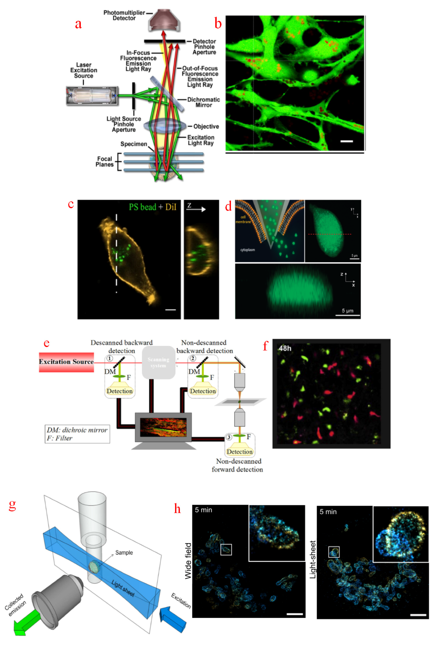
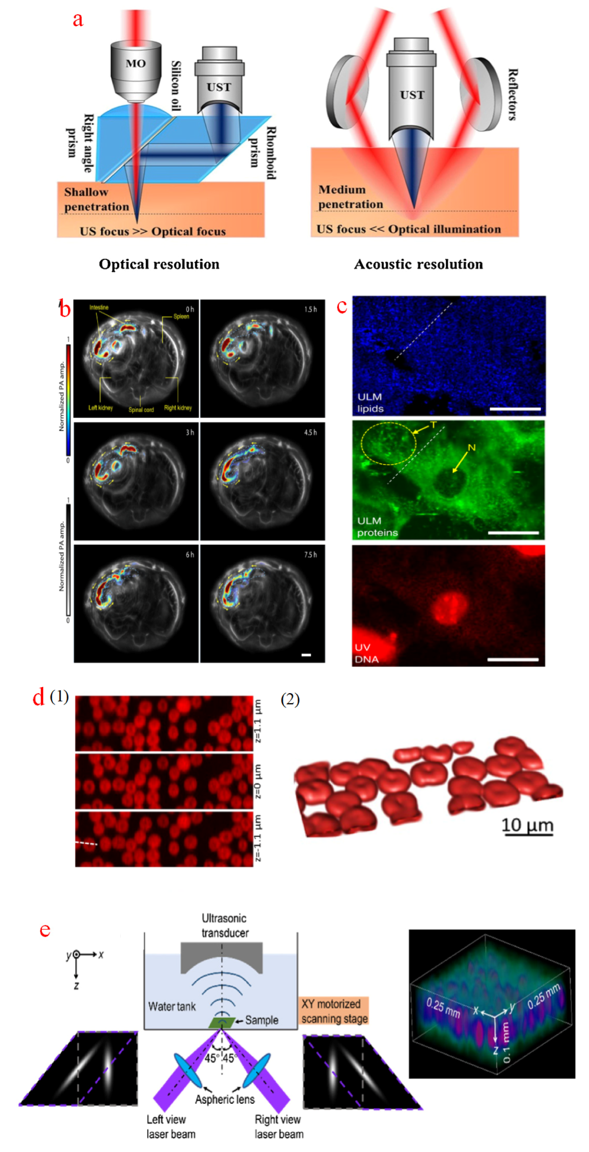
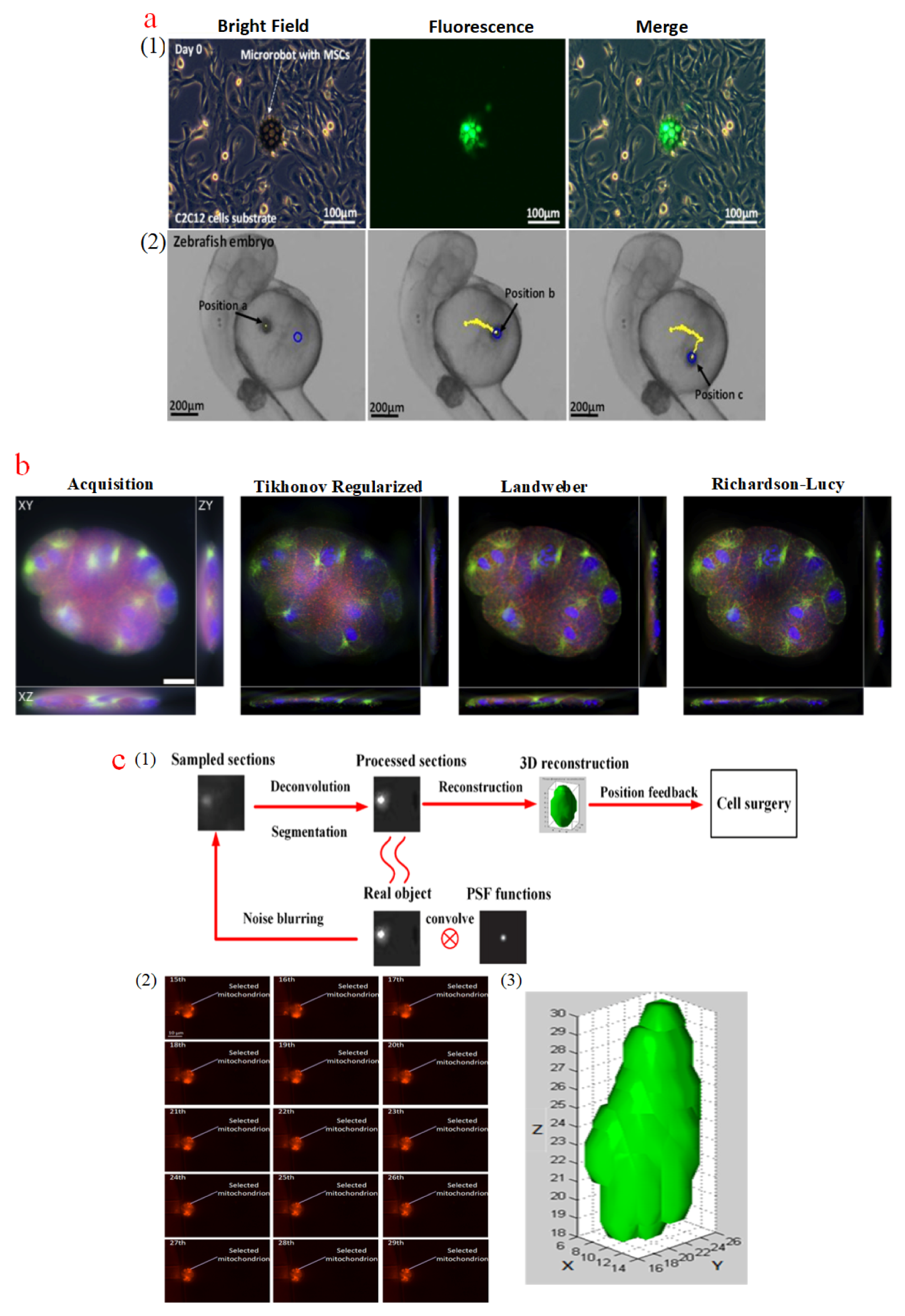
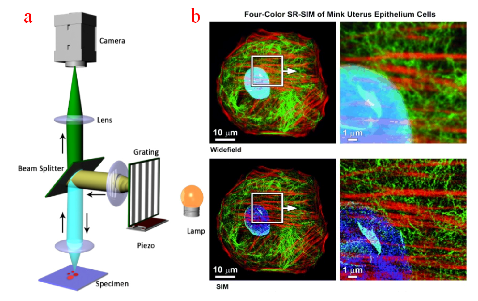
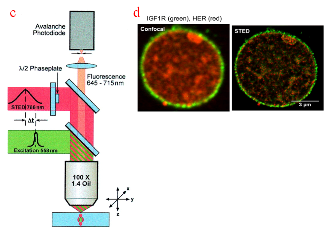
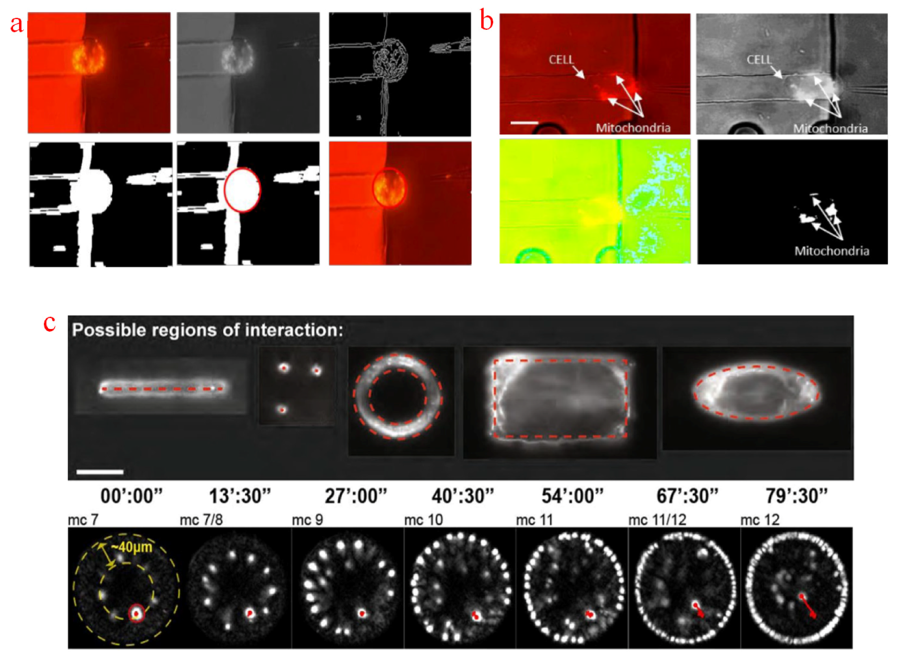
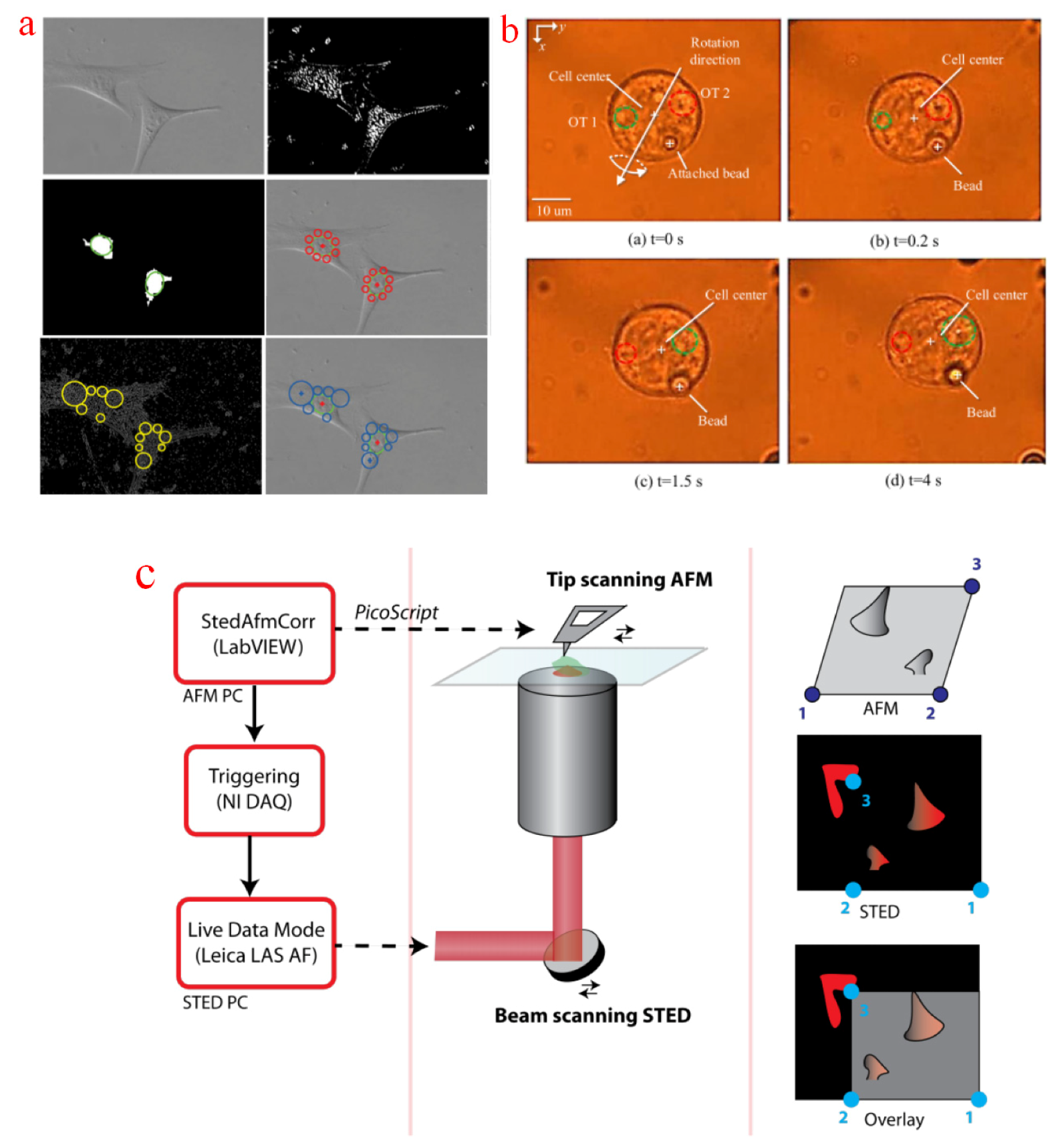
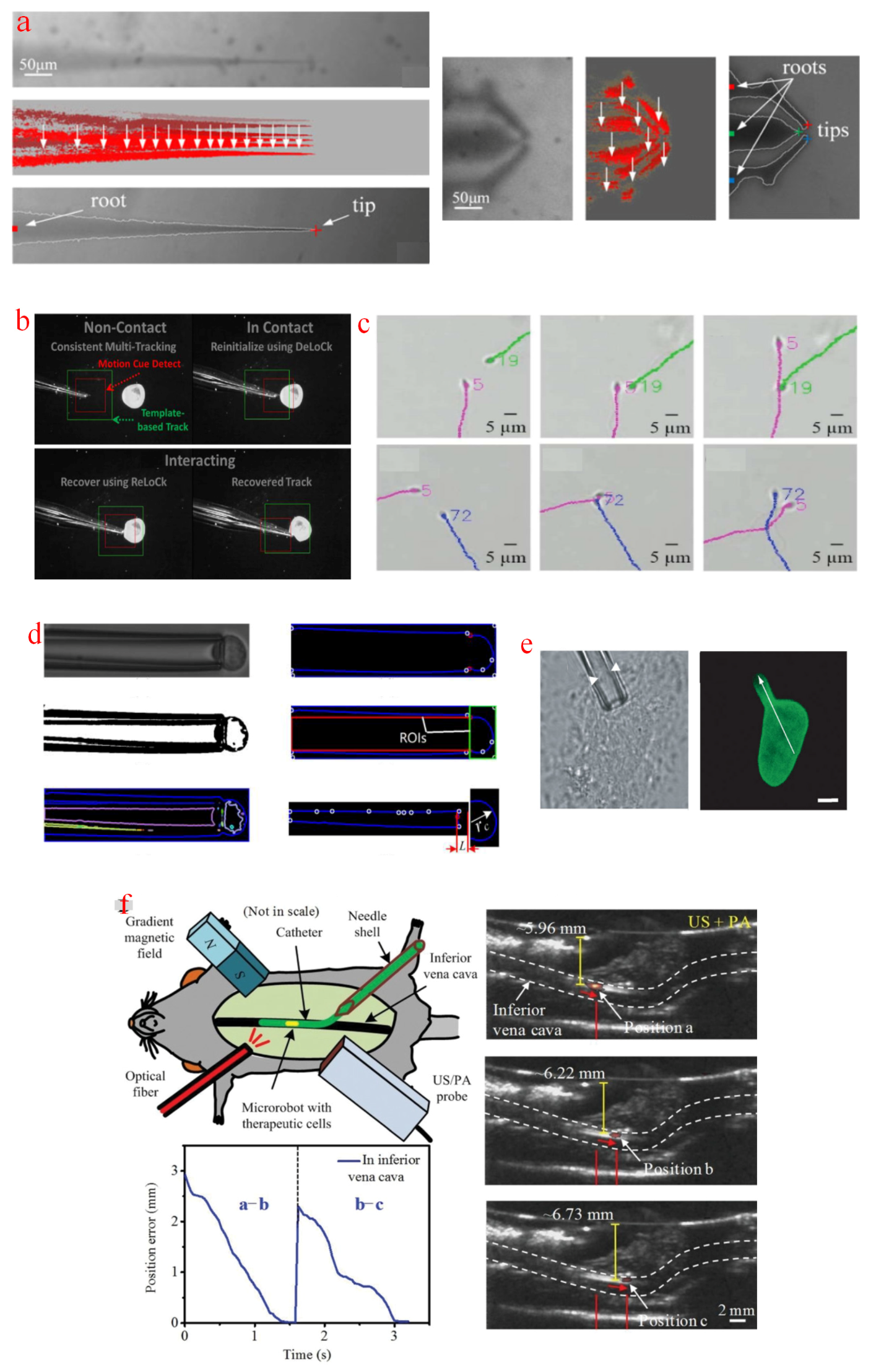
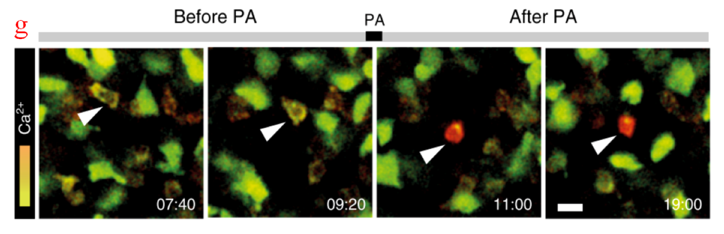
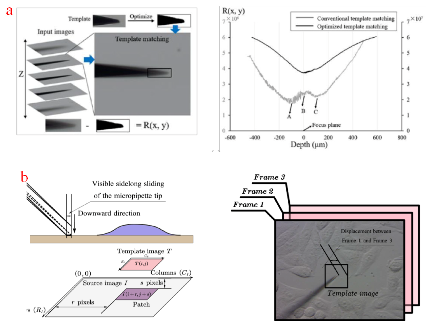
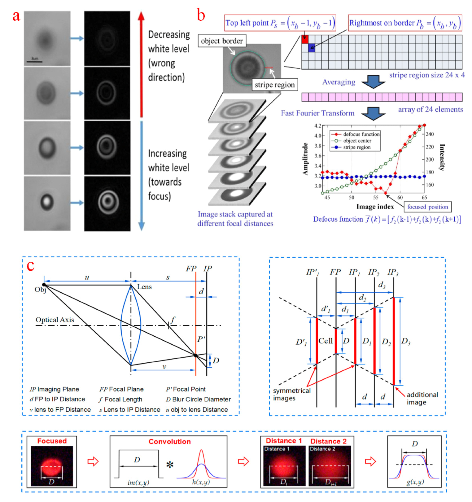
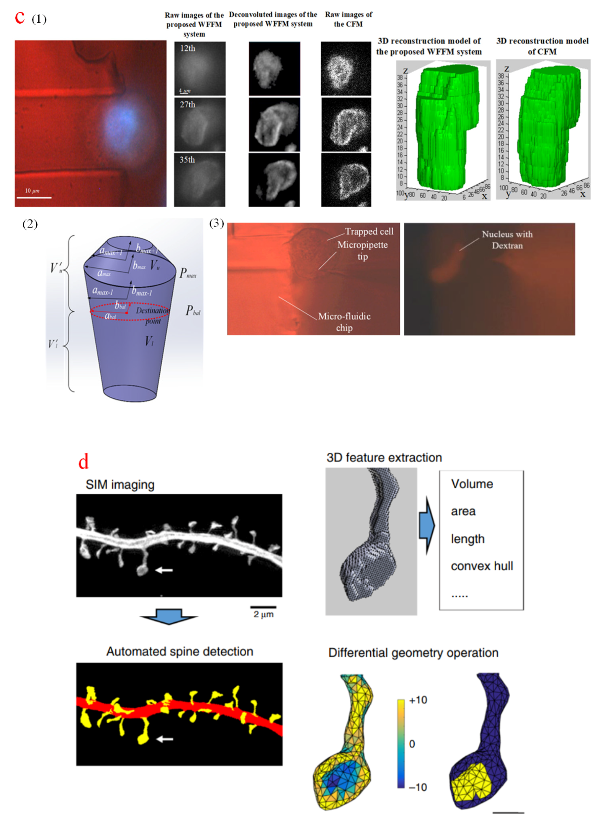
Table 1.
Comparison of image sampling methods based on different principles.
| Methods | Lateral Resolution Level | Axial Resolution Level | Advantages | Limitations | References |
|---|---|---|---|---|---|
| CFM | ~200 nm | ~500 nm | out-of-focus blurs rejection; optical section | high light intensity; slow sampling speed | [42,43,44,45,46,47,48,49,50,51,52,53,54,55] |
| TPFM | ~500 nm | ~1 µm | out-of-focus blurs rejection; high penetration depth; long-term measurement | low sampling rate; relatively low axial resolution; high purchase expenses | [56,57,58,59,60,61,62,63,64,65,66,67,68,69] |
| LSFM | ~300 nm | >1 µm | out-of-focus blurs rejection; long-term measurement | low axial resolution; confined space | [70,71,72,73,74,75,76,77,78,79,80,81,82,83] |
| PAM | ~300 nm | ~2 µm | out-of-focus blurs rejection; high penetration depth; label-free measurement | slow sampling speed; complicated configuration; unavailable commercially | [84,85,86,87,88,89,90,91,92,93,94,95] |
| WFFM | ~400 nm | >800 nm | low purchase cost; great compatibility; | out-of-focus blurs; low resolution | [96,97,98,99,100,101,102,103,104,105,106,107] |
| SIM | <100 nm | <300 nm | high resolution; out-of-focus blurs rejection | specimen fixation; high purchase costs | [108,109,110,111, 118,119,121] |
| STEDM | <100 nm | <100 nm | high resolution; out-of-focus blurs rejection | high light intensity; high purchase costs | [107,112,113,114,115,116, 120,122] |
Table 2.
Comparison of various image computational processing methods for intracellular micromanipulation.
Table 2.
Comparison of various image computational processing methods for intracellular micromanipulation.
| Methods | Sampling Method | Advantages | Limitations | ||
|---|---|---|---|---|---|
| Segmentation | Otsu thresholding [123] | WFFM | morphological smoothing | only for cell center localization; interferences of noises and blurs | |
| Canny edge detector [124] | WFFM | gauss noise filter; circle transformation | only for circular specimens; interferences of noises and blurs | ||
| Sobel edge detector [125] | WFFM | morphological smoothing | only for cell existence determination; interferences of noises and blurs | ||
| HSV value thresholding [126] | WFFM | more accurate thresholding value; median noise filter | interferences of noises and blurs | ||
| Interaction segmentation [127] | LSFM | out-of-focus blurs rejection; full-time measurement | Only for indirect manipulation | ||
| Planar localization | Feature points | K-means cluster [128] | WFFM | accurate nucleus and cytoplasm detection | only for attached cells |
| Potential edge [130] | WFFM | simple operation | only for poly-body; not for images without poly-body; susceptible to noises and blurs | ||
| Polybead attachment [132] | WFFM | high compatibility | complicated attachment procedures; susceptible to noises and surroundings | ||
| Inherent features [133] | WFFM | high compatibility | need individual selection; susceptible to noises and surroundings | ||
| Bright point filter [135] | STEDM | simple operation | susceptible to interferences of surrounding bright points | ||
| Motion history image [136] | WFFM | simple operation; high-speed | only for simple application with no interferences | ||
| Reinitialization and recovery mechanism [137] | WFFM | specimen contact and appearance tracking | complicated procedures, slow speed | ||
| Tracking | Confidence-based hybrid method [138] | WFFM | high tracking robustness | complicated procedures, slow speed | |
| Modified joint probabilistic data association filter [139] | WFFM | multiple sperm tracking; physical property measurement; high tracking robustness | only for sperm tracking; limited applications; | ||
| Two ROI separation [141,142,143] | WFFM | real-time measurement | complicated procedures; susceptible to noises and blurs | ||
| CFM measurement [144] | CFM | accurate measurement; simple image processing | high sampling light intensity; long sampling time; | ||
| PAM navigation [145] | PAM | deep imaging depth; in vivo measurement | Only for measurement in large tissues and organs | ||
| Actuator activiation and tracking [146] | TPFM | long term measurement; single cell manipulation | Only for photosensitive microrobots | ||
| Micropipette tip template [147] | WFFM | simple operation | anterior–posterior ambiguity; new template requirement; | ||
| Gradient template [148] | WFFM | ambiguity elimination; improved accuracy | susceptible to interferences;new template requirement | ||
| Depth acquisition | Template matching | Template similarity score differences [149,150] | WFFM | misalignment compensation; suitable for uncalibrated system | complicated procedures; slow speed; new template requirement |
| Three-frames template [151] | WFFM | simple operation; fast speed | only for contact judgment | ||
| Centroid template [152] | WFFM | simple operation | only for cell pairing; an aditional template requirement for a new cell | ||
| Entropy computation [153] | WFFM | no manual selection of the template | susceptible to interferences; large number of sampled images for computation; slow speed | ||
| Edge pixel intensity [154] | WFFM | highlighted edge | susceptible to noises and blurs; artifacts existing in edges | ||
| Autofocusing | Depth from border intensity variation [155,156] | WFFM | inaccurate boundary compensation; improved accuracy | complicated procedures; slow speed | |
| Multiple depth from defocus [157,158] | WFFM | simple operation; fast speed; relative depth acquisition | inaccurate optical model; inaccurate cell diameter estimation | ||
| Non-uniform rational B-splines [159] | WFFM | multiple biomembranes reconstruction; fast reconstruction | inaccurate shape assumption | ||
| 3D analysis | Four intersections ellipsoid estimation [161] | WFFM | simple reconstruction | inaccurate shape assumption; complicated contact detection | |
| Alpha-shape algorithm [162] | WFFM | boundary extracted from multiple depths; close-to-real morphology | interferences of noises and blurs; artificial contours | ||
| CFM reconstruction [163,164] | CFM | directed measurement; blurs and noises rejection; simple operation | long sampling time; phototoxicity; high purchase cost | ||
| Noise-regulated maximum likelihood estimation (NRMLE) deconvolution and filtered segmentation algorithm [165] | WFFM | accurate image restoration; elimination of blurs and noises; fluorescence concentration compensation | relatively long computation time; only for immobilized specimens | ||
| Computational 3D geometry analysis [166] | SIM | high resolution; Long-term measurement | only for structure analysis of immobilized specimens | ||
Publisher’s Note: MDPI stays neutral with regard to jurisdictional claims in published maps and institutional affiliations. |
© 2020 by the authors. Licensee MDPI, Basel, Switzerland. This article is an open access article distributed under the terms and conditions of the Creative Commons Attribution (CC BY) license (http://creativecommons.org/licenses/by/4.0/).
Share and Cite
MDPI and ACS Style
Gao, W.; Zhao, L.; Jiang, Z.; Sun, D. Advanced Biological Imaging for Intracellular Micromanipulation: Methods and Applications. Appl. Sci. 2020, 10, 7308. https://doi.org/10.3390/app10207308
AMA Style
Gao W, Zhao L, Jiang Z, Sun D. Advanced Biological Imaging for Intracellular Micromanipulation: Methods and Applications. Applied Sciences. 2020; 10(20):7308. https://doi.org/10.3390/app10207308
Chicago/Turabian StyleGao, Wendi, Libo Zhao, Zhuangde Jiang, and Dong Sun. 2020. "Advanced Biological Imaging for Intracellular Micromanipulation: Methods and Applications" Applied Sciences 10, no. 20: 7308. https://doi.org/10.3390/app10207308
Note that from the first issue of 2016, this journal uses article numbers instead of page numbers. See further details here.