Thermo-Optic Numerical Research on Segmented Circular LD Arrays Side-Pumping a Nd:YAG Laser Rod


1
Key Laboratory of Photonic Control Technology (Tsinghua University), Ministry of Education, Beijing 100084, China
2
State Key Laboratory of Precision Measurement Technology and Instruments, Department of Precision Instrument, Tsinghua University, Beijing 100084, China
3
Science and Technology on Electro-Optical Information Security Control Laboratory, Tianjin 300308, China
4
China Academy of Space Technology, Beijing 100094, China
*
Author to whom correspondence should be addressed.
Appl. Sci. 2020, 10(20), 7316; https://doi.org/10.3390/app10207316
Submission received: 22 July 2020
/
Revised: 2 September 2020
/
Accepted: 14 October 2020
/
Published: 19 October 2020
(This article belongs to the Collection Optical Design and Engineering)
Abstract
:Featured Application
A numerical analysis method is provided as an efficient design tool for the side-pumping lasers of laser diode (LD) arrays. The temperature distributions and thermo-optic effects of the laser rod in the segmented circular LD array side-pumping configuration are analyzed and contrasted with those of other configurations. The numerical results indicate that this segmented scheme has the potential to be used in compact and miniature laser systems.
Abstract
The configuration designs of the laser diode (LD) side-pumping laser rods focus on how to solve the space conflict between the pump and heat-removal devices because both want to use the larger lateral surface of the laser rod. The conflict is better balanced in the three different side-pumping geometries: the segmented circular LD array side-pumping configuration, the annular liquid-cooling structure, and the compensated semicircular LD array side-pumping arrangement. The temperature distributions and thermo-optic effects of the laser rod in the segmented circular LD array side-pumping configuration are analyzed in contrast with those in the other arrangements. The numerical results indicate that the periodical segment-pumping scheme provides higher beam quality than the compensated semicircular side-pumping scheme, enabling removal of the complex liquid cooling system in medium-power applications, thus showing the potential to be used in compact and miniature laser systems.
1. Introduction
For the side-pumping geometry of lasers, the liquid cooling systems are often designed to cool the laser rod and pump-source [1,2], decrease the influence of thermo-optic effects [3], and ensure a stable laser output with high beam quality [4]. The laser rod, immersed in the fluid of the transparent coolant jacket, is pumped by the outside circular laser diode (LD) arrays; this arrangement effectively avoids the space conflict. The symmetrical annular pump leads to Gaussian gain distribution in the laser rod and thus to high-power laser output with high beam quality [1,5]. Therefore, the annular liquid-cooling is the most commonly used method in side-pumping geometry, especially in high-power applications [2,6]. However, the complex liquid cooling systems considerably increase the volume of lasers and decrease mobility.
In conduction cooling side-pumped lasers, there are two typical geometries. One is the compensated semicircular LD array side-pumping arrangement, in which the two same semicircular LD structures are configured with each other in a compensated geometry [7]. In the semicircular LD side-pumping structure, the cylindrical half-surface of the laser rod is conductively cooled by a heat sink, and the other half-surface is arranged to absorb pump radiation. The asymmetrical pump geometry induces non-Gaussian gain distribution in the laser rod. However, the laser beam quality is improved to a certain extent by the compensated geometry of the two same semicircular LD structures. The other typical geometry is the segmented circular LD array side-pumping configuration, in which the multi-circular LD array and rod holders alternate periodically along the length of the laser rod [8,9]. The symmetrical side-pumping structure directly induces heat flows to propagate along the axial of the laser rod rather than the radial direction to the surface of the laser rod, thereby avoiding a high radial temperature gradient. Finally, the heat is removed by the segmented holders. This scheme reduces the thermal lensing caused by the radial temperature gradient and has been demonstrated in applications of Q-switched neodymium-doped yttrium aluminum garnet (Nd:YAG) [10] and Raman [11,12] lasers. However, no detailed comparative research has yet been conducted on the temperature distributions and thermo-optic effects in laser rods between this scheme and the other side-pumping schemes under the same cooling boundary conditions.
The current work is an extension of our previous work [8], with our prime motivation being to provide a numerical analysis method as an efficient design tool for compact and miniature side-pumped lasers, especially for segmented circular LD array side pumping lasers. In this paper, the temperature distributions and thermo-optic effects of laser rods in these three different side-pumping schemes are comparatively analyzed under the same cooling boundary conditions. The relative merits are discussed. The numerical results reveal that the segmented side-pumping scheme is an effective method to decrease thermal lensing and to miniaturize laser systems, especially in medium-power applications.
2. Materials and Methods
2.1. Side-Pumping Configurations
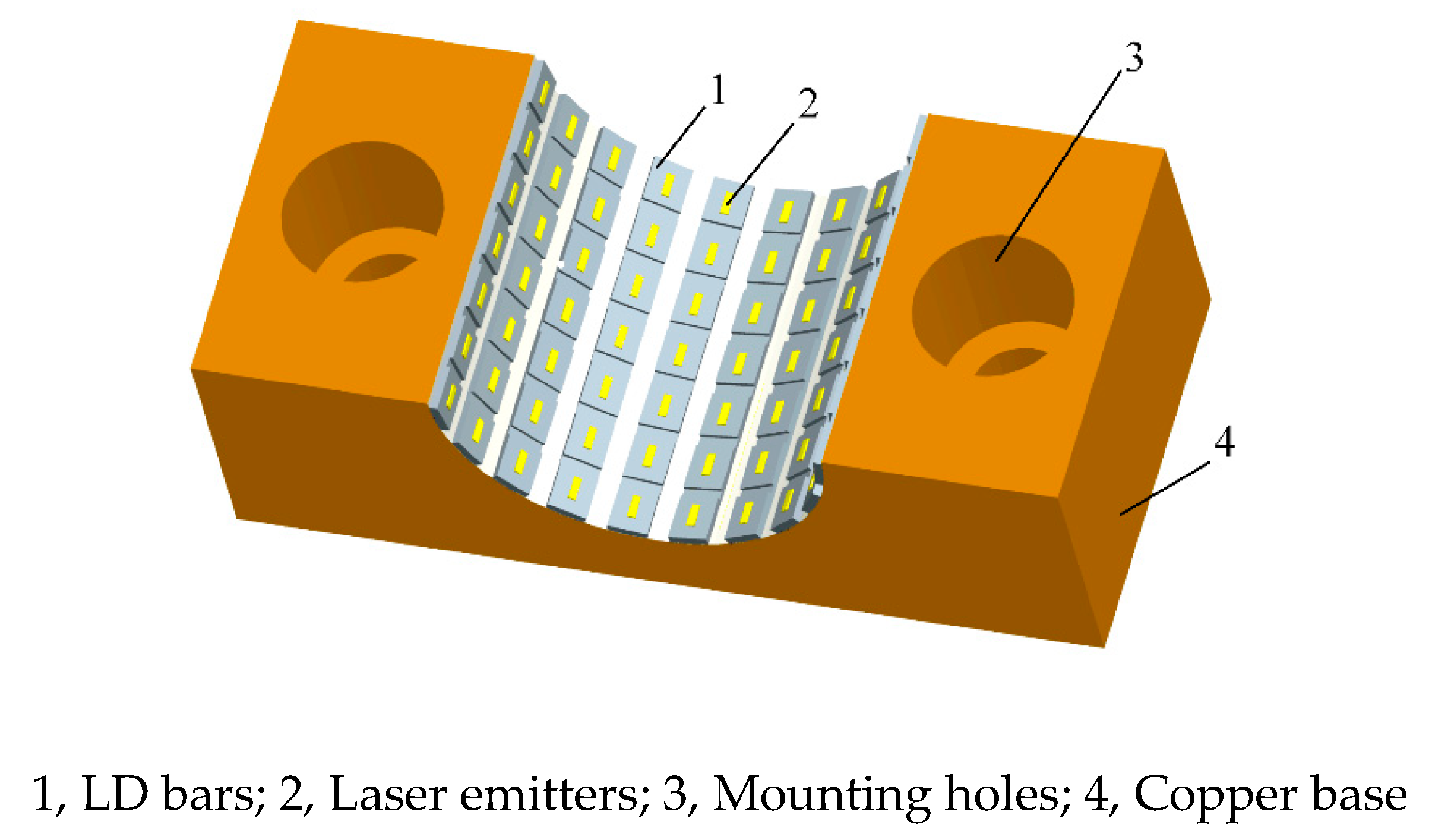
In Figure 1, the upper and lower heat sink has a comb shape with four rod holders that are responsible for supporting and cooling the rod. An Nd:YAG rod in the middle of the circular structure is clamped by the holders in the upper and lower heat sink. Each LD array mounted on the upper and lower heat sink has a semicircular structure, and the LD bars are arranged along the axis of the Nd:YAG rod. The face-to-face configuration of the upper and lower semicircular LD arrays forms a circular periodical side-pumping geometry. The heat produced by the LD arrays and Nd:YAG crystal is conducted to the heat sinks cooled by thermoelectric coolers (TEs). Two fans are used to generate airflows that pass over the outside heat exchangers to dissipate the heat into the surrounding air [8].
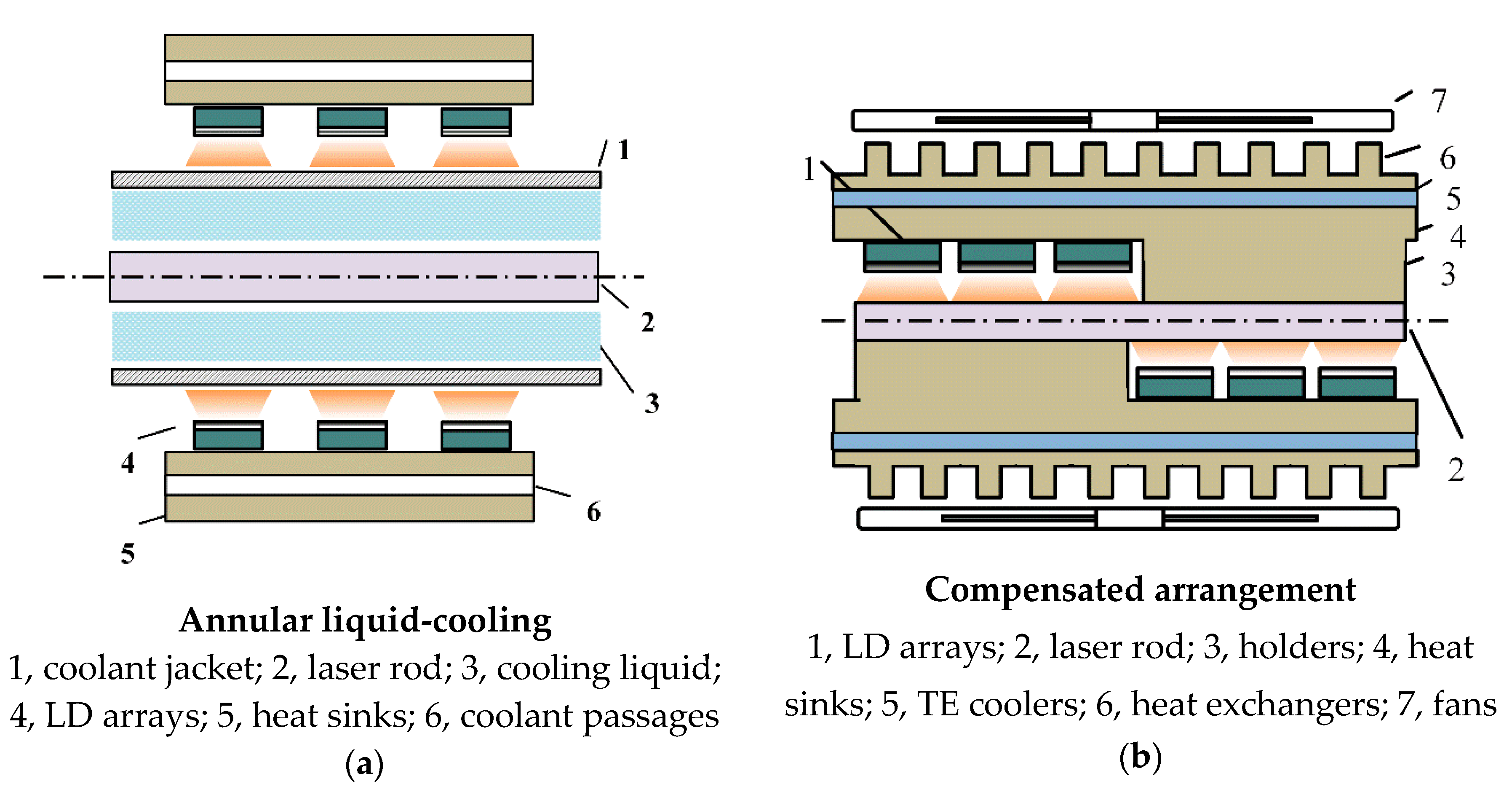
For comparative research of the temperature distributions and thermo-optic effects in laser rods, we considered the annular liquid cooling and the compensated semicircular LD array side-pumping configuration models, as shown in Figure 2.
In the annular liquid cooling scheme as shown in Figure 2a, a laser rod is immersed into the fluid of the transparent coolant jacket. The laser rod is surrounded by the six outside semicircular LD arrays and has circular pump geometry. The LD arrays are placed along the length of the laser rod, and the pump light at wavelength 808 nm is transverse to the direction of the 1064 nm laser beam. In addition, the liquid passages in heat sinks are designed to cool LD arrays.
In the compensated semicircular LD array side-pumping scheme as shown in Figure 2b, three semicircular LD arrays are mounted on a heat sink with one holder. The pump and holders have a face-to-face arrangement. On the left side of Figure 2b, the Nd:YAG rod is pumped from the upper semicircular LD arrays and bonded to the lower holder on the heat sink. Conversely, the Nd:YAG rod is pumped from the lower semicircular LD arrays and bonded to the upper holder in the right of Figure 2b. Therefore, the two same semicircular LD pump and holder structures form a compensated side-pumping scheme. The temperature of heat sinks is controlled by both the TEs and outside fans.
2.2. Theory Models
A ray-tracing method was used to build an inner heat-sources model of the laser rod. A linear LD array has an effective emitting area of about 1.0 μm by 4 mm. In the direction of the LD bar’s fast axis, the pump beam has an approximately Gaussian shape and a larger beam divergence angle of 40°. The laser diodes are considered as point light sources because of the small emitting width of 1.0 μm. In our simulation, the pump beam parallel to a profile of the laser rod was discretized to be rays carrying energy along the beam divergence angle. In contrast, the pump beam in the direction of the LD bar’s slow axis had an approximate flat-top shape and a smaller beam divergence angle of 10°. The pump power distribution along the direction of the laser rod axis (the LD’s slow axis) was deemed to be uniform within a pump segment because of the longer-width (10 mm) LD bars. Therefore, the inner heat-sources distribution was determined by tracing all pump rays in the laser rod cross-section.
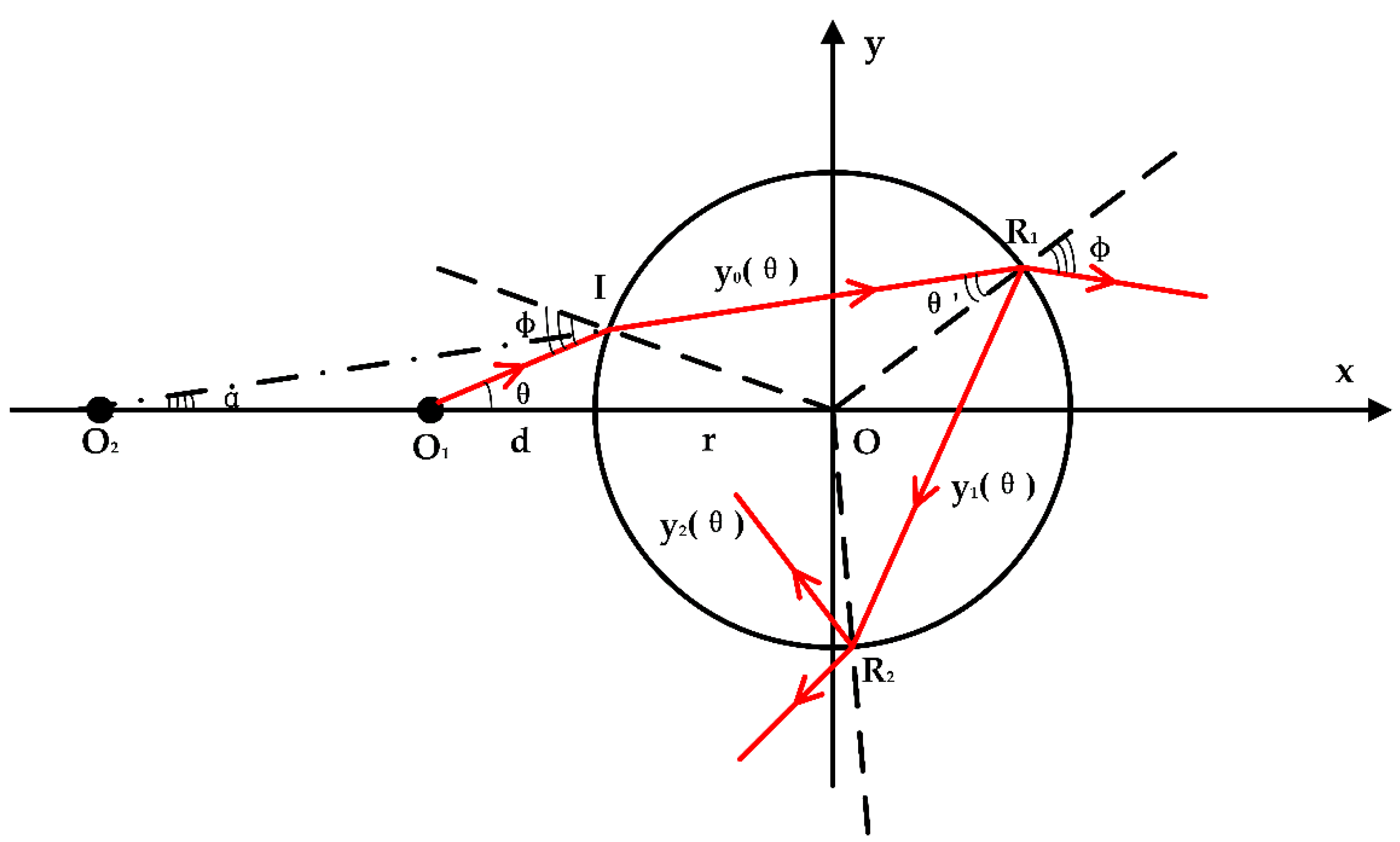
Figure 3 illustrates the ray-tracing in a laser rod cross-section from any ray in the LD beam divergence angle. The x,y-coordinate system is established with the origin at the center of the laser rod, and the angles between rays and x-axis are defined as positive angles in the condition of counterclockwise rotation from x-direction to the direction of ray propagation. The point O1 indicates a laser diode emitter. Any ray of O1I is refracted into the laser rod at the incidence point I, and the coordinates (xI, yI) are obtained by:
where is the angle of the ray from a laser diode and the x-direction, r is the radius of the laser rod, and d is the distance between O1 and the surface of the laser rod.
With some geometry and the law of refraction, the angle of between the ray IR1 and the x-direction is solved by:
where and are the incidence and refraction angles at the incident point I, respectively.
With the coordinates (xI, yI) and the angle , the refraction ray of IR1 is expressed as:
The refraction ray is reflected first at point R1, second at R2, and nth at RN. With the same method, the coordinates of R1(x1, y1), R2(x2, y2), RN(xN, yN), and the angles between the corresponding reflection ray and the x-direction are determined. Using the method of induction, the general expression of the reflected rays is written as:
where n is the number of rays reflected in the inner surface of the laser rod.
According to the Fresnel formulae, the reflectivity of a laser rod’s inner surface is solved by:
where and are the incidence and refraction angles in the plane of incidence, respectively; and are the reflectivity of s and p waves, respectively; and is the angle of the E vector of the incident wave with the plane of incidence.
Then, the power carried by the nth reflective wave at the reflective point of RN is expressed as:
where indicates the power of the incident wave at the reflective point RN.
Line O1I in Figure 3 indicates any incident ray from a laser diode whose light power is:
where is the angle of the ray and the x-axis, is half of the beam divergence angle in the direction of the fast axis, and A is a normalized coefficient:
where is the power produced by a laser diode.
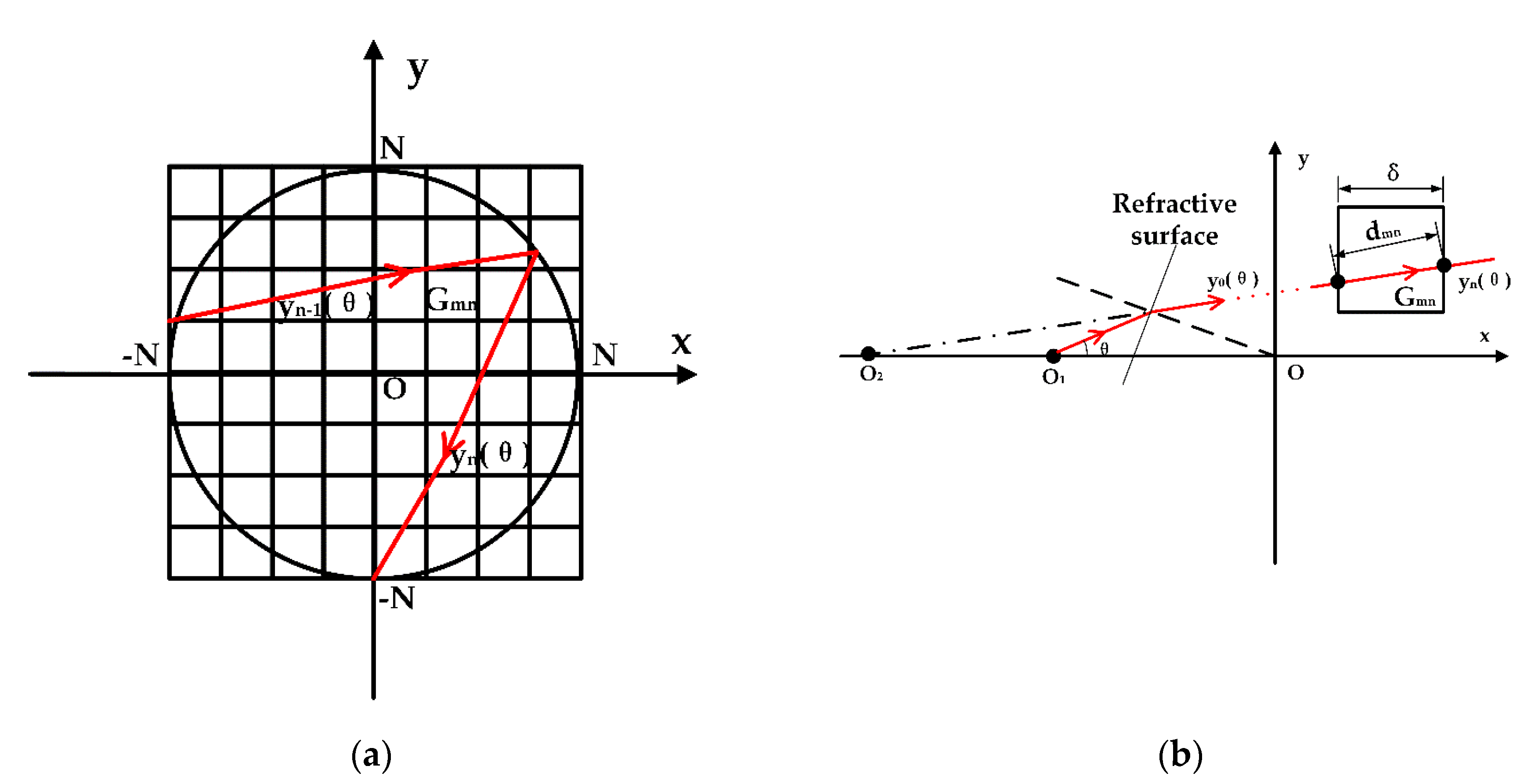
Based on gridding the profiles of the laser rod, the absorbed power of the grids was calculated by tracing all rays emitted from around laser diodes within the beam divergence angle of − to . Figure 4a shows a gridding profile of the laser rod and Figure 4b depicts the absorbed power of a grid from any ray of .
In Figure 4a, the laser rod cross-section is discretized as the grids of 2N × 2N, and the length of a grid is:
In Figure 4b, the length of the ray through any grid Gmn is calculated using the geometry method. The absorbed power of grid Gmn from the ray of is written in the form:
where is the power carried by the ray of before inputting the grid Gmn, and is the absorption coefficient of the laser rod.
Then, the absorbed power of grid Gmn from a laser diode is obtained using the integral in the beam divergence angle:
where i is the mark number of a laser diode around the profile of the laser rod.
The x,y-coordinate system rotation around origin O is used to trace the rays from laser diodes not on the x-axis, and the rotation equations are written as:
where is the rotation angle of the x,y-coordinate system.
There are laser diodes around the profile of the laser rod. Thus, the inner heat source density profile Z0 along the length (z-direction) of the laser rod is expressed as:
where is the quantum efficiency and is the pump time.
The temperature distributions of in an isotropic Nd:YAG rod is solved using the finite element analysis (FEA) method [13] from the heat equation:
where is the density, is the specific heat, is the thermal conductivity, is the inner-sources density, and denotes the gradient operator.
In steady-state conditions, Equation (14) can be rewritten as:
For Nd:YAG crystal, is normally assumed to be constant with moderate temperature increases. Under higher heat load conditions, is given in the first approximation [14] by:
where is the reference temperature of the cooling heat sinks, is the heat conductivity at , and is the difference in .
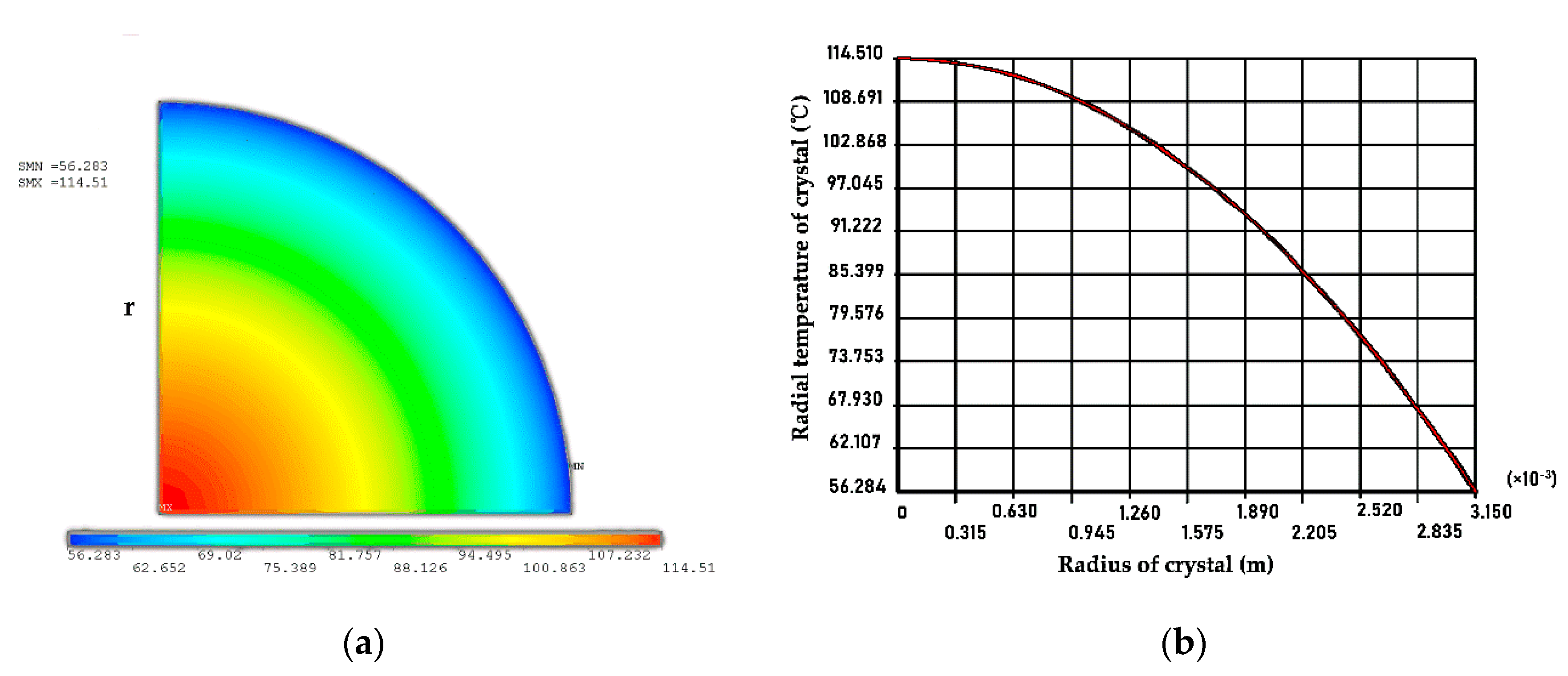
With the help of Equations (13) and (14), we used ANSYS software (ANSYS, Canonsburg, PA, USA) to calculate the radial temperature distribution of the laser rod with liquid cooling as previously described [1] ch.7, and the result is illustrated in Figure 5a,b. Figure 5a shows the radial temperature profile of the laser rod corresponding to the radial temperature curve shown in Figure 5b. Comparing Figure 5b with the Figure 7.1 in [1], the results agree well, which validates the accuracy and validity of the numerical models.
The temperature-dependent variation of the refractive index provides the main contribution to the thermal lens. The variation in the refractive index caused by that of temperature is:
where is the ambient temperature and is the change in the refractive index with temperature.
From Equation (17), the refractive index distribution in the laser rod is written in the form:
where is the refractive index of the laser rod in ambient temperature, and is the variation in the refractive index in the laser rod.
The average refractive index profile of the laser rod is obtained by the integral along the length of the laser rod:
Then, the complex amplitude equivalent transfer function of the laser rod is expressed as:
Where is the wave vector and is the length of the laser rod.
The laser rod is considered as a phase plate with refractive index distribution and Fresnel diffraction propagation distance . For the thermal-lensing of the laser rod, the phase plate was illuminated using a coherent planar wave at 1064 nm in the simulation, and the wave-front distortion after a planar wave passing through the laser rod of length was evaluated by:
where is the amplitude of the planar wave, the x–y plane is the incident plane z of in the laser rod, the x’–y’ plane is the output plane z of in the laser rod.
Finally, the optical distortions influenced by thermo-optic effects were evaluated using Equation (21).
2.3. Simulation Methods and Boundary Conditions
The details of the simulation methods and processes are described in the following. Firstly, we used MATLAB software (MathWorks, Natick, MA, USA) to calculate the inner heat source density of the laser rods in three different side-pumping schemes according to the same boundary conditions with the help of the derived Equation (13). Secondly, the temperature distributions of in the laser rods were analyzed and discussed by deriving Equation (14) considering heat conduction using FEA in ANSYS software (ANSYS, Canonsburg, PA, USA), because the major contribution to the thermal lens was from the temperature-dependent variation of the refractive index. Thirdly, MATLAB software (MathWorks, Natick, MA, USA) was used again to obtain the change in the refractive index in the laser rod using Equation (17) and the complex amplitude equivalent transfer function of laser rod by deriving Equation (20). Next, a planar wave was employed to measure the thermal lensing in the laser rod. The wave-front distortion after a planar wave passing through the laser rods was determined using Equation (21) in MATLAB (MathWorks, Natick, MA, USA). Finally, the thermo-optic effects in the laser rods were further evaluated in three different side-pumping schemes.
In our simulations, the variations in the refractive index caused by thermal stress were not considered due to the minimal influence in low- and medium-power applications. In addition, the end effects were ignored because their influence is rather limited in the side-pumping configuration.
To facilitate comparison, it was necessary to set the same boundary conditions in the three different side-pumping configurations.
In the side-pumping configurations models, the same Nd:YAG rods with a diameter of 5 mm and length of 65 mm were employed. The properties of the Nd:YAG used in the simulation are listed in Table 1.
The same semicircular LD array modules were used in the three different side-pumping schemes. A three-dimensional (3D) geometrical model of semicircular LD arrays is shown in Figure 6.
Ten bars 10 mm in length and 1.4 mm in width were fixed on the surface with a 5 mm radius of curvature. A bar of peak power of 100 W contained 10–20 independent laser emitters and the laser output produced by an emitter was emitted from a 200 × 1.0 μm area with a 40° fast axis × 10° slow axis beam divergence. The peak power output of a semicircular LD array is about 1000 W and six semicircular LD arrays were employed in the three different side-pumping schemes, corresponding to a total peak power of 6000 W. The LD arrays with a center wavelength of 808 nm worked at a pumping rate of 10 Hz with a pump pulse duration of 230 μs, and the wavelength changed with the temperature at 0.3 nm/°C. The copper base on which the semicircular LD arrays were mounted was a cuboid with a length of 20 mm, a width of 10 mm, and a height of 15 mm, with screws on the heat sink. The properties and parameters of the semicircular LD array modules used in the simulation are listed in Table 2.
In the model of the segmented scheme shown in Figure 1, the length of the circular holder was about 8 mm and that of the circular pump was 10 mm. The cooled cylindrical surfaces of the laser rod, on which the boundary conditions of heat conduction were a constant reference temperature of 25 °C under Dirichlet conditions, were controlled at 25 °C by the temperature controllers. In contrast, the boundary conditions of the thermal simulation were assumed to be a convective heat transfer of zero to the surrounding air (Neumann condition) on the pumped cylindrical surfaces of the laser rod.
In the model of the liquid-cooling scheme shown in Figure 2a, the boundary conditions for the heat equation were assumed to be a constant reference temperature of 25 °C under Dirichlet conditions on the cooled cylindrical surface of the laser rod.
In the model of the compensated scheme shown in Figure 2b, the length of the pump region containing three semicircular LD modules was about 30 mm and that of the cooling region was 32 mm. The boundary conditions of heat were also assumed to be a constant reference temperature of 25 °C under Dirichlet conditions on the cooled cylindrical half-surfaces of the laser rod, and the boundary conditions of the thermal simulation included a convective heat transfer of zero to the surrounding air (Neumann condition) on the pumped cylindrical half-surfaces of the laser rod.
In the three different side-pumping schemes, the initial temperature conditions were set to an ambient temperature of 25 °C. A thermal conductivity of 14 Wm−1K−1 at 300 K (27 °C) in the laser rod was used in our simulation because of moderate temperature increases in a lower heat load application.
Any traced ray of was multi-reflected at the inner surface of the laser rod, which has the same reflectivity due to having the same incident angles. To minimize calculation, the number n of reflections needed to be determined in the simulation. At the maximum laser diode beam divergence angle of 40° corresponding to 20° of , the reflectivity of 5.6% was obtained according to the Fresnel formulae in Equation (5). The power carried by the second reflective wave can be ignored according to Equation (6). So, the number of reflections was set to be 1 in our simulation.
The boundary conditions and parameters in the thermal simulation are summarized in Table 3.
3. Results and Discussion
3.1. Temperature Distributions
The temperature distributions and values indicate the change in the refractive index, through which the thermo-optic effects are further investigated, and the gain distribution in the laser rod, which influences the laser beam quality [1].
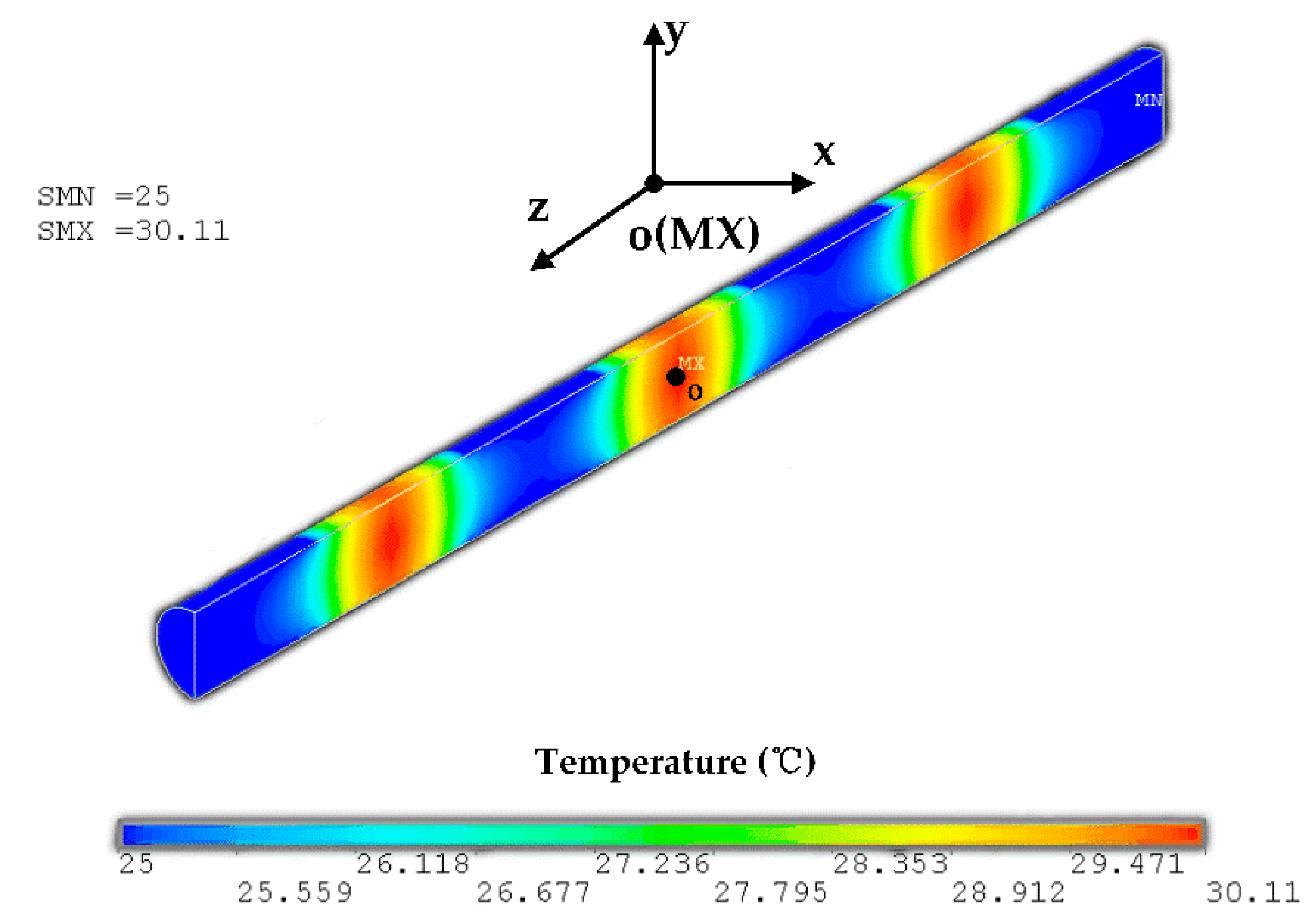
Figure 7 shows the temperature distribution of the laser rod in the segmented scheme.
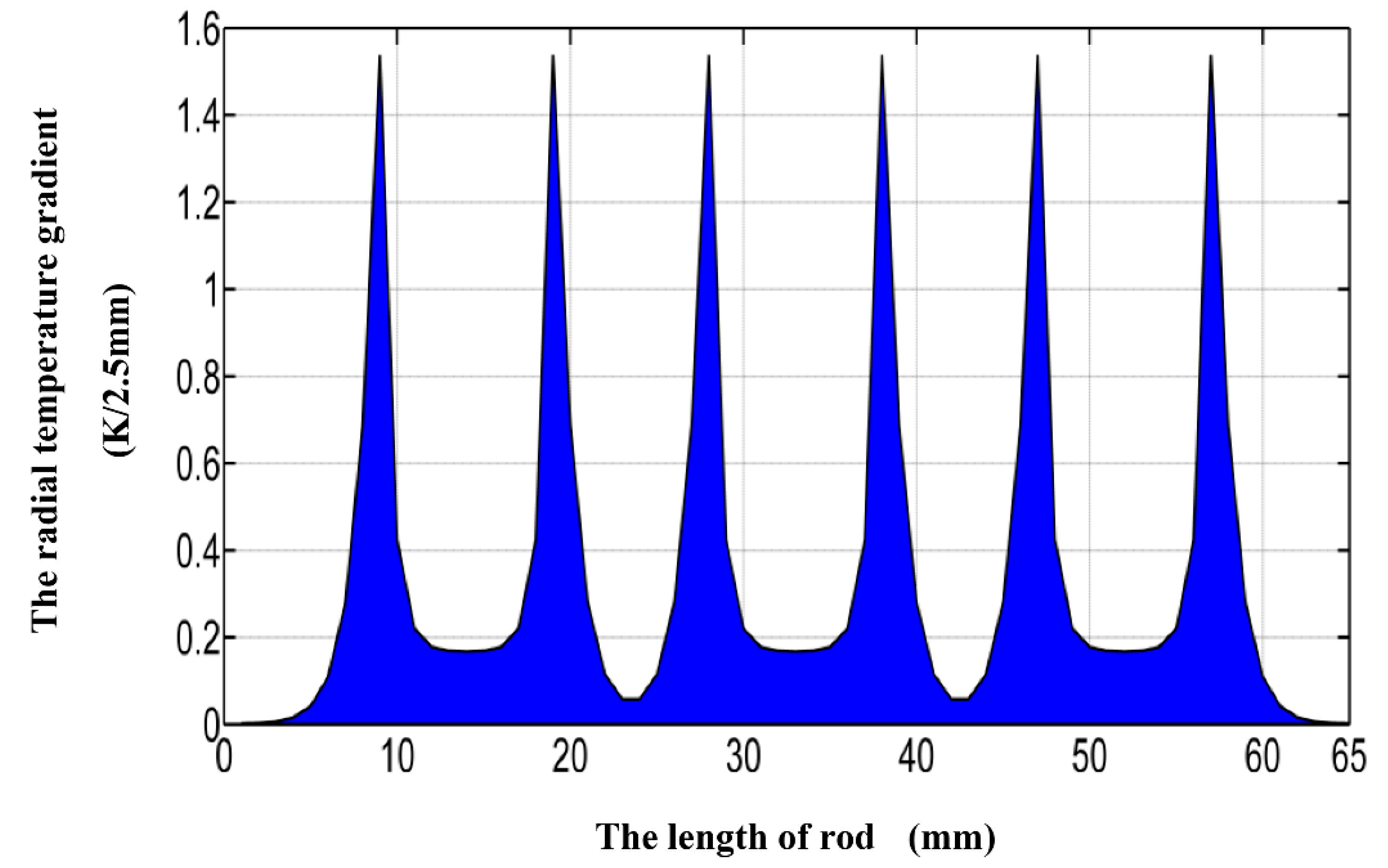
The distribution was axisymmetric about the center of the laser rod, whose maximum temperature was 30.11 °C and the minimum temperature was 25 °C at the cooled cylindrical surfaces of the laser rod. The radial temperature gradient as a function of the length of the rod is illustrated in Figure 8.
There were six peaks at the joints of the pump and holder segment as a result of the heat flow propagating along the length of the rod. Notably, the thermal resistance between the holders and the surface of the rod was not considered. As a result, some peaks are steep. The averaging temperature profile of the laser rod, obtained by averaging the temperatures of points along the length of the rod, showed a rather small radial temperature gradient of 0.35 °C/2.5 mm as shown in Figure 9. Figure 9 shows that the gain had a good Gaussian distribution due to the symmetrical pump arrangement.
The segmented symmetrical side-pumping configuration induces heat flows to propagate along the z-axis of the laser rod rather than directly in the radial direction to the surface of the laser rod in the pumped segments because the boundary conditions on the pumped cylindrical surfaces of the laser rod are in an adiabatic condition (Neumann condition). The heat flows into the cooled segments and is removed by the segmented holders. So, the structure setup avoids higher temperature gradients in the radial direction.
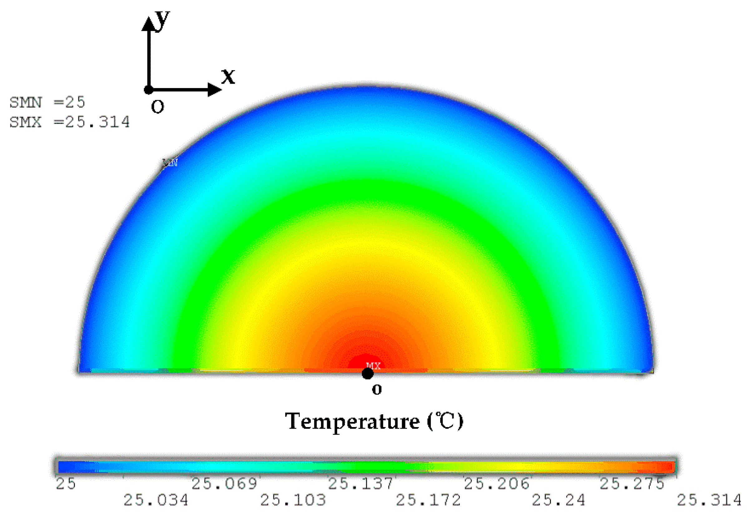
Figure 10 illustrates the averaging temperature profile of the laser rod in the annular liquid-cooling scheme. The distribution is symmetrically axial, with a maximum temperature of 25.314 °C, and the radial temperature gradient of 0.314 °C/2.5 mm is rather small. The radial temperature distribution revealed that the gain has a good Gaussian shape.
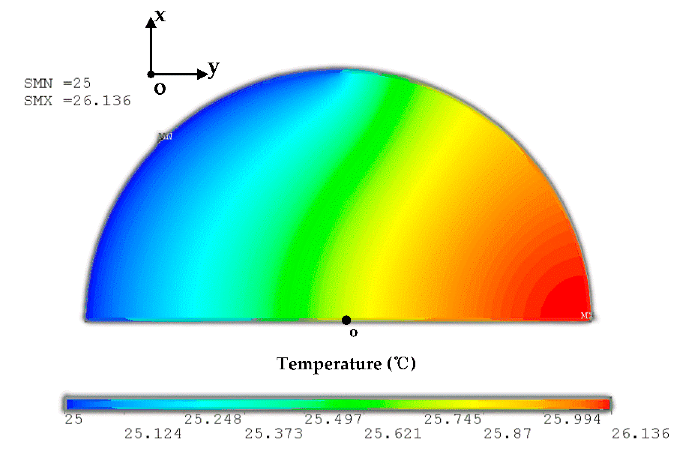
The compensated semicircular LD array side-pumping scheme has two identical pumps and heat-removal structures. The temperature profile of the laser rod in each pump and heat-removal structure has a circular asymmetrical distribution, as shown in Figure 11, but is symmetrical about the y-axis. A maximum temperature of 26.136 °C was recorded at the surface of the laser rod along the y-axis incident pump. The diametrical temperature gradient of 1.136 °C/5 mm in the y-direction was higher than that in the annular liquid-cooling and segmented side-pumping schemes.
The average temperature profile of the laser rod after compensation by the two same structures, which was obtained by averaging the temperatures of the points along the length of the laser rod, is shown in Figure 12. The profile showed an almost saddle shape with a maximum radial temperature gradient of 0.38/2.5 mm in the x-axis direction. The minimum radial temperature gradient of 0.1/2.5 mm, which was the result of compensation in the y-axis direction, is rather small. The numerical results implied that the difference in the gradients will be reduced and a better Gaussian gain distribution can be obtained if the compensation in the x-axis direction can be employed.
3.2. Thermo-Optic Effects
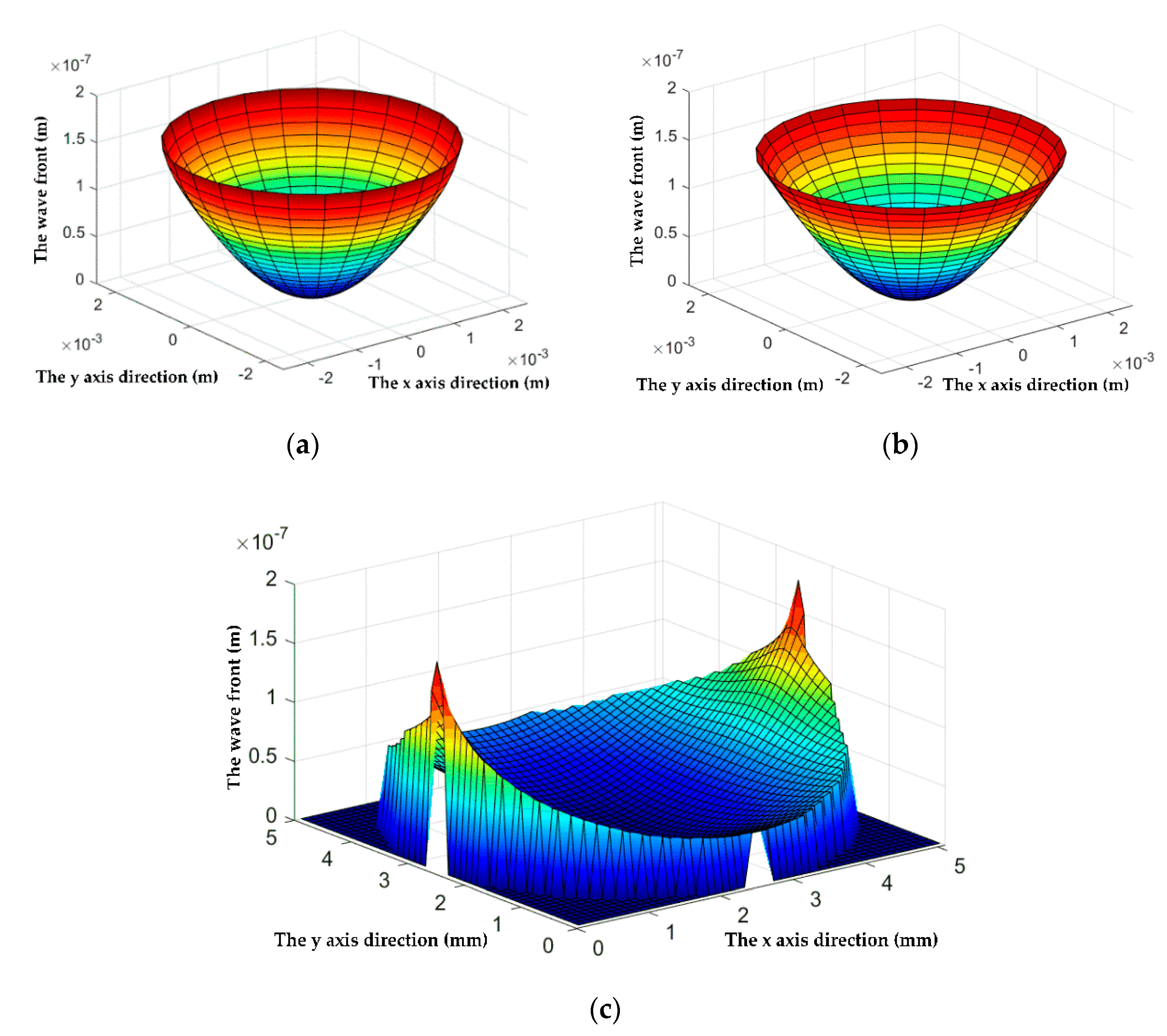
Based on the temperature-dependent variation in the refractive index, we investigated the optical distortions caused by the thermal effects of laser rods in the three different side-pumping schemes. The wave-fronts, after a planar wave passed through the laser rods, are illustrated in Figure 13.
The optical distortion in the segmented side-pumping scheme shown in Figure 13a is close to that in the annular liquid-cooling scheme as shown in Figure 13b; both are a near-spherical wave, from which the influence of heat is interpreted as the behavior of a thick lens. The optical distortion in the compensated scheme shown in Figure 13c has an asymmetrical wave-front that is regarded as formed by the two spherical waves of different curve radii in the x and y directions. The curve radius in the x-direction is close to that in Figure 13a,b but that in the y-direction is rather long, which implied that the thermal lens of the laser rod is a bifocal lens with different focal lengths in the x and y directions.
According to the numerical results above, the performance of the laser rods in the three side-pumping schemes is summarized in Table 4.
4. Conclusions
In summary, the thermo-optic numerical research on LD arrays side-pumping an Nd:YAG laser rod was demonstrated for three different side-pumping schemes and a numerical analysis method as an efficient analysis design tool is provided for compact and miniature side-pumping lasers. The temperature distributions and thermo-optic analyses of laser rods in the segmented circular LD array side-pumping configuration were examined in contrast with those in the annular liquid-cooling and compensated semicircular LD array side-pumping configurations The numerical results revealed that the segmented side-pumping scheme has a higher beam quality and provides an effective method to remove the complex liquid cooling system in medium power applications. The mobility and portability were enhanced due to the small volume of the laser system. We predict that this scheme has the potential to be used in compact and miniature laser systems.
Author Contributions
Conceptualization, W.W.; methodology, W.W. and Q.Z. (Qin Zhao); formal analysis, Q.Z. (Qin Zhao) and Z.H.; investigation, Q.Z. (Qin Zhao), W.G. and S.Y.; writing—original draft preparation, W.W. and Q.Z. (Qihang Zhao). All authors have read and agreed to the published version of the manuscript.
Funding
This research was funded by the open fund of Science and Technology on Electro-Optical Information Security Control Laboratory, grant number 61421070201.
Conflicts of Interest
The authors declare no conflict of interest.
References
- Koechner, W. Solid-State Laser Engineering; Springer: New York, NY, USA, 2006. [Google Scholar]
- Grechin, S.G.; Nikolaev, P.P. Diode-side-pumped laser heads for solid-state lasers. Quantum Electron. 2009, 39, 1–17. [Google Scholar] [CrossRef]
- Yu, D.; Tang, D. Experimental study of a high-power CW side-pumped Nd:YAG laser. Opt. Laser Technol. 2003, 35, 37–42. [Google Scholar] [CrossRef]
- Pinto, R.D.S.; Geskus, D.; Wetter, N.U. 45W CW TEM00 mode diode-side-pumped Nd:YAG rod laser with linearly polarized beam. In Proceedings of the 2014 Conference on Lasers and Electro-Optics (CLEO)—Laser Science to Photonic Applications, San Jose, CA, USA, 8–13 June 2014. JTh2A.82. [Google Scholar]
- Bruesselbach, H.; Sumida, D. A 2.65-kW Yb:YAG single-rod laser. IEEE J. Sel. Top. Quantum Electron. 2005, 11, 600–603. [Google Scholar] [CrossRef]
- Sundar, R.; Ranganathan, K.; Hedaoo, P.; Bindra, K.S. Modular pump head design of diffused, metal, and hybrid pump geometry for diode-side-pumped high power Nd:YAG laser. Appl. Opt 2016, 55, 7530–7537. [Google Scholar] [CrossRef] [PubMed]
- Guo, Y.X.; Gong, M.L.; Xue, H.Z.; Li, C.; Yan, P.; Liu, Q.; Chen, G. Laser diodes semicircular side-pumped laser rod with a round-sharped output. Laser Phys. Lett. 2006, 3, 345–348. [Google Scholar] [CrossRef]
- Wang, W.; Gong, M.L.; Zhao, Q.; Hu, Z.Y.; Fu, C. Segmented circular LD arrays side-pumped a Nd:YAG laser rod. Laser Phys. 2010, 20, 1344–1349. [Google Scholar] [CrossRef]
- Zhang, Y.; Gu, H.; Cui, L.; Jiang, J.; Hao, H. Research on the LD side pumping field of solid-state lasers. High Power Lasers Technol. Syst. Platf. Effects III 2019, 11162, 1116205. [Google Scholar] [CrossRef]
- Wang, W.; Fu, C.; Hu, Z.; Zhao, Q.; Gong, M. Segment side-pumped Q-switched Nd:YAG laser. Appl. Opt. 2012, 51, 1765–1770. [Google Scholar] [CrossRef] [PubMed]
- Wang, W.; Gong, M.; Hu, Z.; Zhao, Q.; Fu, C. Efficient high-output diode side-pumped electro-optical Q-switched Nd:YAG/KGd(WO4)2Raman laser with conductive and air cooling. Laser Phys. Lett. 2010, 7, 294–297. [Google Scholar] [CrossRef]
- Wang, W.; Gong, M.; Zhao, Q.; Hu, Z.; Fu, C. Diode-pumped Q-switched Nd:YAG-KGW Raman laser operating in two-color modulation. Opt. Express 2010, 18, 2655–2661. [Google Scholar] [CrossRef] [PubMed]
- Brown, D. Ultrahigh-average-power diode-pumped Nd:YAG and Yb:YAG lasers. IEEE J. Quantum Electron. 1997, 33, 861–873. [Google Scholar] [CrossRef]
- Cini, L.; MacKenzie, J.I. Analytical thermal model for end-pumped solid-state lasers. Appl. Phys. A 2017, 123, 1–14. [Google Scholar] [CrossRef] [PubMed] [Green Version]
Figure 1.
Segmented circular laser diode (LD) array side-pumping configuration.

Figure 2.
(a) The annular liquid-cooling configuration; (b) compensated semicircular LD arrays side-pumping arrangement.
Figure 2.
(a) The annular liquid-cooling configuration; (b) compensated semicircular LD arrays side-pumping arrangement.

Figure 3.
Schematic of ray-tracing.

Figure 4.
(a) Gridding profile of laser rod; (b) absorbed power of a grid from any ray of .

Figure 5.
Validation of temperature models: (a) The radial temperature profile, (b) calculated temperature curve.
Figure 5.
Validation of temperature models: (a) The radial temperature profile, (b) calculated temperature curve.

Figure 6.
A three-dimensional (3D) view of the LD module (10 × 20 × 15 mm).

Figure 7.
The temperature distribution of the laser rod with the segmented scheme.

Figure 8.
The radial temperature gradient as a function of the length of the rod.

Figure 9.
The averaging temperature profile of the laser rod in the segmented side-pumping scheme.

Figure 10.
The average temperature profile of the laser rod in the annular liquid-cooling scheme.

Figure 11.
The temperature profile of the laser rod in each pump and heat-removal structure.

Figure 12.
The average temperature profile of the laser rod in the compensated side-pumping scheme.

Figure 13.
The wave-fronts after a planar wave passed through the laser rods in the (a) segmented, (b) liquid-cooling, and (c) compensated schemes.
Figure 13.
The wave-fronts after a planar wave passed through the laser rods in the (a) segmented, (b) liquid-cooling, and (c) compensated schemes.


Table 1.
The properties of the Nd:YAG used in the simulation.
| Properties/Parameters | Neodymium Doped Yttrium Aluminum Garnet (Nd:YAG) |
|---|---|
| Diameter (mm) | 5 |
| Length (mm) | 65 |
| Dopant concentration (atm %) | 1.0 |
| Absorption coefficient (m−1) | 400 |
| Density (gcm−1) | 4.56 |
| Specific heat (Wsg−1K−1) | 0.59 |
| Refractive index | 1.86 |
| Change in refractive index with temperature (K−1) | 7.3 × 10⁻⁶ |
| Heat conductivity (Wm−1K−1) | 14 |
Table 2.
The properties and parameters of semicircular LD arrays modules used in the simulation.
| Properties/Parameters | Semicircular LD Modules |
|---|---|
| Peak power (W) | 1000 |
| Center wavelength (nm) | 808 |
| Wavelength changes with temperature (nm/°C) | 0.3 |
| Beam divergence fast axis/slow axis | 40°/10° |
| Pump pulse duration (μs) | 230 |
| Pumping rate (Hz) | 10 |
| Length of pump (mm) | 10 |
| Radius of curvature (mm) | 5 |
Table 3.
The boundary conditions and parameters in the thermal simulation.
| Boundary Conditions /Parameters | Segmented Model | Liquid-Cooling Model | Compensated Model |
|---|---|---|---|
| Number of semicircular LD modules | 6 | 6 | 6 |
| Total peak power of pump (W) | 6000 | 6000 | 6000 |
| Length of circular cool | 3 × 8 mm | 65 mm | — |
| Length of semicircular cool | — | — | 2 × 32 mm |
| Length of circular pump | 3 × 10 mm | 3 × 10 mm | — |
| Length of semicircular pump | — | — | 2 × 30 mm |
| Initial temperature conditions (°C) | 25 | 25 | 25 |
| Boundary conditions on cooled (°C) surfaces of crystal | 25 (Dirichlet condition) | 25 (Dirichlet condition) | 25 (Dirichlet condition) |
| Boundary conditions on pumped surfaces of crystal | Adiabatic condition (Neumann condition) | Adiabatic condition (Neumann condition) | Adiabatic condition (Neumann condition) |
| Thermal conductivity Κ(T) of crystal (Wm−1K−1) | 14 | 14 | 14 |
| Number n of reflections in crystal | 1 | 1 | 1 |
Table 4.
The performance of the laser rods in three side-pumping schemes.
| Scheme | Annular Liquid-Cooling | Segmented Configuration | Compensated Configuration |
|---|---|---|---|
| Average temperature profile | Parabolic | Parabolic | Saddle shape |
| Radial temperature gradient | Small | Small | Varying |
| Optical distortion | Minimal (spherical) | Minimal (spherical) | More (bifocal) |
| Gain distribution | good | good | Bad |
Publisher’s Note: MDPI stays neutral with regard to jurisdictional claims in published maps and institutional affiliations. |
© 2020 by the authors. Licensee MDPI, Basel, Switzerland. This article is an open access article distributed under the terms and conditions of the Creative Commons Attribution (CC BY) license (http://creativecommons.org/licenses/by/4.0/).
Share and Cite
MDPI and ACS Style
Wang, W.; Zhao, Q.; Gao, W.; Hu, Z.; Zhao, Q.; Yang, S. Thermo-Optic Numerical Research on Segmented Circular LD Arrays Side-Pumping a Nd:YAG Laser Rod. Appl. Sci. 2020, 10, 7316. https://doi.org/10.3390/app10207316
AMA Style
Wang W, Zhao Q, Gao W, Hu Z, Zhao Q, Yang S. Thermo-Optic Numerical Research on Segmented Circular LD Arrays Side-Pumping a Nd:YAG Laser Rod. Applied Sciences. 2020; 10(20):7316. https://doi.org/10.3390/app10207316
Chicago/Turabian StyleWang, Wei, Qin Zhao, Wenqing Gao, Zhenyue Hu, Qihang Zhao, and Sen Yang. 2020. "Thermo-Optic Numerical Research on Segmented Circular LD Arrays Side-Pumping a Nd:YAG Laser Rod" Applied Sciences 10, no. 20: 7316. https://doi.org/10.3390/app10207316
Note that from the first issue of 2016, this journal uses article numbers instead of page numbers. See further details here.