Article

Study on Deformation Characteristics and Microstructure Evolution of 2205/AH36 Bimetal Composite in a Novel Hot Forming Process

1
School of Mechanical, Materials, Mechatronic and Biomedical Engineering, University of Wollongong, Wollongong, NSW 2522, Australia
2
Baosteel Research Institute (R&D Centre), Baoshan Iron & Steel Co., Ltd., Shanghai 200431, China
*
Author to whom correspondence should be addressed.
Metals 2020, 10(10), 1375; https://doi.org/10.3390/met10101375
Submission received: 2 October 2020 / Revised: 11 October 2020 / Accepted: 14 October 2020 / Published: 15 October 2020
(This article belongs to the Section Metal Casting, Forming and Heat Treatment)

Abstract

:
A new hot forming process of a hot-rolled 2205 duplex stainless/AH36 low-carbon steel bimetal composite (2205/AH36 BC) was proposed in this study, using the Gleeble 3500 thermal-mechanical simulator and hot bending tools. The deformation characteristics of 2205/AH36 BC were studied by hot tensile tests at temperatures from 950 to 1250 °C and strain rates ranging from 0.01 to 1 s−1. The tensile temperature has a great influence on the peak flow stress of the bimetal composite. The main microstructure evolution mechanisms, including dynamic recovery (DRV) and dynamic recrystallization (DRX), changed with the deformation temperatures. The different strain rates and the change of strain rates during the deformation process have an influence on the flow behavior of the bimetal composite. During the hot bending process, qualified parts could be formed successfully without obvious cracks in the interfacial zone. Phase and grain orientation spread (GOS) maps of specimens after hot tensile and forming tests were obtained by the electron backscatter diffraction (EBSD) technique to study the microstructure evolution, respectively. It is found that the effect of the working temperature on microstructure evolution is larger than that of the stacking sequence for 2205/AH36 BC. The considerable geometrically necessary dislocation (GND) accumulation occurs around the interface of 2205/AH36 BC under all imposed working conditions after the hot bending process, due to the interfacial micro-defects and complex stress states.

1. Introduction

Demand for the multi-functionality and durability of engineering materials in worldwide industries has increased greatly due to the gradually stricter environmental regulations, and bimetal and laminated composites produced by two or more dissimilar constituent materials have become popular for applications in many fields, such as automobile, aerospace and chemical pressure vessels [1,2,3,4,5]. The principal objective of developing bimetal composites is to combine the benefits of both constituent materials for applications where the full-gauge alloy construction is not required. By combining, for instance, a layer of high-manganese steel with a thick layer of high-strength steel, it is possible to simultaneously benefit from the properties of the high-strength steel and the wear resistance of the high-manganese steel. Generally, the thickness of explosive cladding or hot roll bonding composite plates is not small, and the size of industrial products fabricated with these composite plates is often large [6,7]. The hard workability of medium-thickness bimetal composite plates is still a processing challenge to produce final parts with acceptable geometries and properties. In an attempt to respond to such a problem, the hot working processing of metals, including hot forming and forging [8,9,10], is suitable and cost-efficient to be employed, in which the weak and ductile metals are deformed instead of the strong state at lower temperatures.
The mechanical properties of the metal or alloys are mainly dependent on the thermo-mechanical history and the microstructure after hot working [11,12]. Hot compression, tensile and torsion tests were often adopted to investigate the hot deformation and microstructure characteristics of metals [13,14,15,16,17,18,19]. Cheng et al. [20] investigated the deformation behaviors of magnesium alloy based on hot tensile tests. Li et al. [21] studied the flow softening of TC6 alloy during the hot tensile deformation process, and they compared the flow behaviors of metals obtained from the hot tensile and compression tests, respectively. Deng et al. [22] and Huang et al. [23] studied the hot tensile deformation and fracture behaviors of AZ31 magnesium alloy and 42CrMo steel, respectively. Zhang et al. [24] developed a modified Johnson–Cook constitutive model to simulate the dynamic tensile behaviors of 7075/T6 aluminum alloy based on the finite element (FE) method, and they indicated that the fitting of the Johnson–Cook constitutive model can reflect the mechanical properties of 7075/T6 aluminum alloy under different strain rates.
The study of microstructure evolution is another aspect to understand the deformation mechanisms of metals. Generally, the flow behaviors of metals obtained from experiments contain four stages: work hardening, transition, softening and steady stage [13]. In the first stage, the work hardening rate exceeds the softening rate induced by dynamic recovery (DRV), and the stress increases at the small deformation. In the transition period, the competition occurs between the work hardening and softening effect resulting from DRV or dynamic recrystallization (DRX). In the softening stage, the stress decreases quickly, resulting from the DRV or DRX. Finally, in the steady period, the stress becomes stable, achieving a balance between work hardening and softening. Kopec et al. [11] presented a new hot forming process adopting the cold forming tools and a hot blank to study the formability and microstructure evolution mechanisms of Ti6Al4V alloy, and they found that the main microstructure evolution mechanism included the recovery, phase transformation and recrystallization.
Although research has been done related to the hot deformation of metals and alloys, the deformation characteristics of bimetal composites at elevated temperatures have still not been fully investigated. The flow characteristics and microstructure evolution mechanisms of bimetal composites are different from those of a single steel sheet or plate, due to the asynchronous deformation and interaction effect between their constituent metal layers with different mechanical properties, such as ductility and formability, during the hot forming process. It is necessary to have more knowledge and understanding of hot forming and material behavior of bimetal composites, which enables the bimetal or laminated composite to be adopted in industrial applications. In order to forward this aim, this study presented an investigation of a hot bending process for the 2205 duplex stainless/AH36 low-carbon steel bimetal composite (2205/AH36 BC) using a Gleeble 3500 thermal-mechanical test simulator. The hot tensile tests were performed at temperatures ranging from 950 to 1250 °C with the strain rates ranging from 0.01 to 1 s−1 to study the effects of hot working conditions on the hot deformation behavior of the bimetal composite. The hot forming tests were conducted at the temperatures of 950 and 1050 °C. Microstructure evolution after hot tensile and forming was analyzed using the scanning electron microscope (SEM) and EBSD technique (JEOL, Tokyo, Japan). The FE method will also be employed to obtain the stress and strain distributions of the bimetal composite after the hot bending process [25,26,27,28].

2. Experimental Details
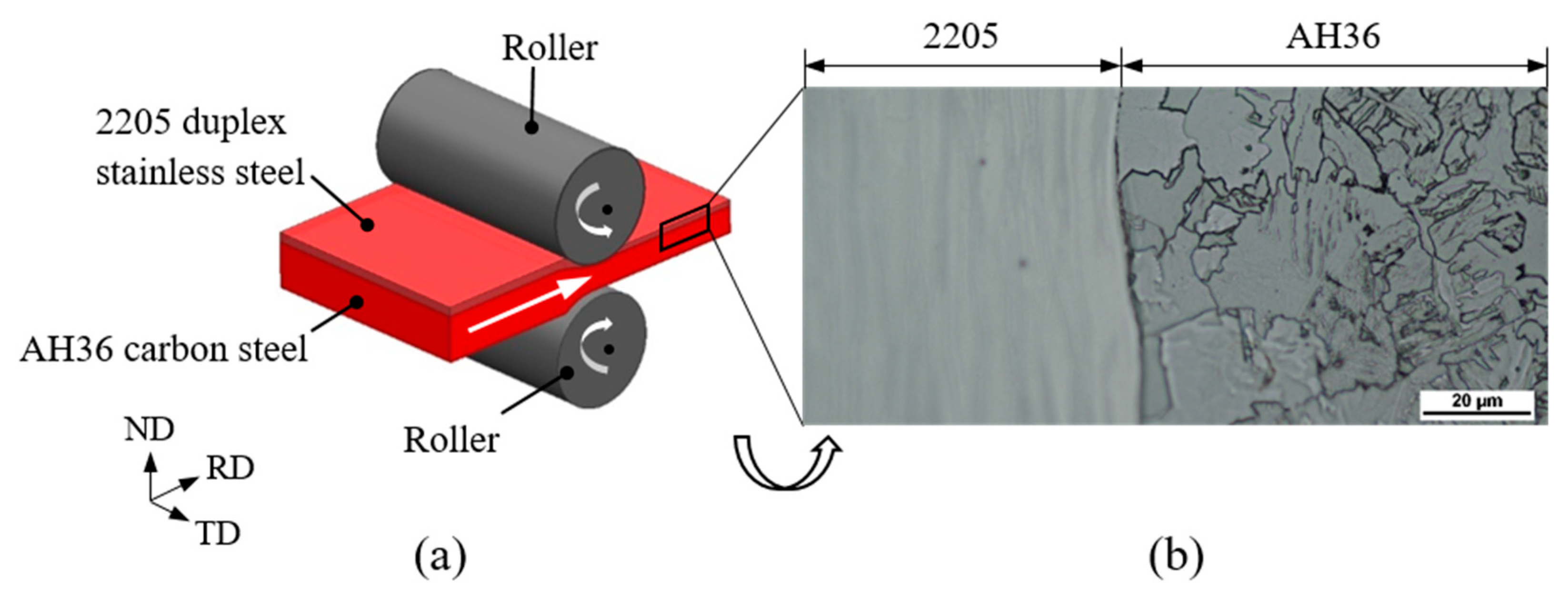
2.1. Materials

A hot-rolled 2205/AH36 BC (Baoshan Iron & Steel Co., Ltd., Shanghai, China), consisting of a 2205 duplex stainless steel layer with the thickness of 3 mm and AH36 low-carbon steel layer with the thickness of 8 mm, was employed in this study, as shown schematically in Figure 1a. The bonding process between two materials was conducted under the combination of a high rolling reduction and an elevated temperature (950 °C), and then water cooling treatment and annealing at 850 °C were carried out, respectively. The nominal composition of the 2205 steel is Fe-21Cr-5.36Ni-3Mo-1.4Mn-0.62Si-0.024C (wt.%), and the chemical composition of the AH36 steel is Fe-0.9Mn-0.5Si-0.4Ni-0.2Cr-0.18C-0.08Mo (wt.%). The metallography of 2205/AH36 BC obtained by the optical microscope is shown in Figure 1b.

2.2. Gleeble Thermal-Mechanical Testing

A Gleeble 3500 thermal-mechanical test simulator (Dynamic Systems Inc., Poestenkill, NY, USA) was employed to carry out the hot tensile tests of 2205/AH36 BC over the elevated temperature range of 950–1250 °C and strain rate range of 0.01–1 s−1. The tensile specimens, including a 2205 steel layer (1.5 mm) and an AH36 steel layer (1.5 mm), were cut from the 2205/AH36 BC plate, and the dimensions of the dog bone-shaped specimens are shown in Figure 2a. The effective gauge length with a uniform temperature region is around 25 mm in this work. The thermocouple was welded using resistance spot welding in the middle of the gauge length to monitor the testing temperature during the deformation process, and the frequency of the temperature measurement is 1000 Hz. Figure 2b,c show the schematic diagram of the testing installation and how the specimen was installed in the Gleeble 3500 simulator, respectively. The testing specimen was heated to the testing temperatures at a rate of 10 °C/s and held for 90 s to homogenize the temperature distribution, which then was proceeded with the testing strain rates, until the specimen was completely broken, followed by quenching to preserve the elevated temperature microstructure. In order to guarantee the repeatability, each test was conducted three times.

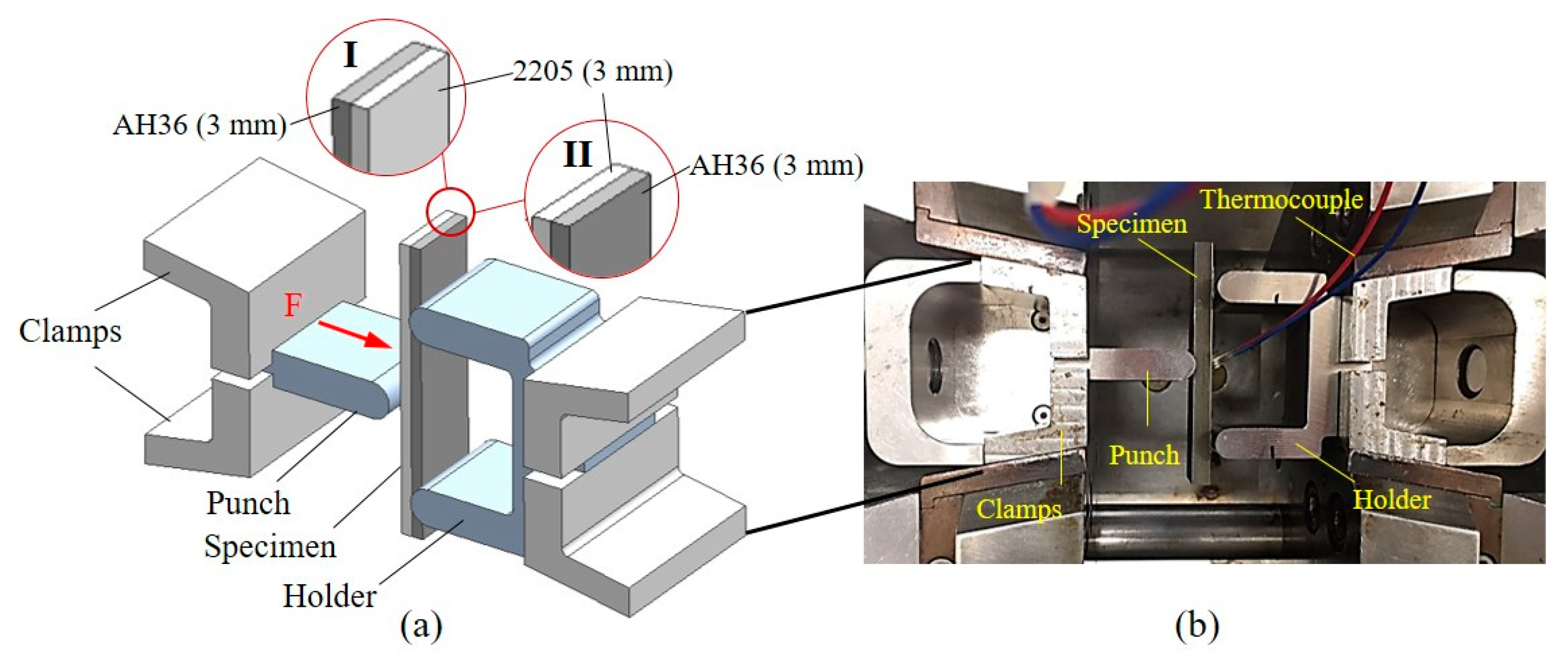
2.3. Hot Forming of Bimetal Composite

In order to investigate the deformation characteristics of the bimetal composite at elevated temperatures, a new setup of hot bending, including a punch, a holder and clamps, was designed and fabricated based on the Gleeble 3500 thermal-mechanical simulator (Dynamic Systems Inc., Poestenkill, NY, US), as shown in Figure 3a. The size of the hot bending specimen is 80 × 20 × 6 mm, and the thickness of 2205 steel and AH36 steel is 3 mm. As the relative position of the component layers has an impact on the formability of the bimetal composite [29], two types of hot bending were conducted in this study: (I) the AH36 steel layer is located inside of the bent specimen, contacting with the punch during the deformation process; (II) the second condition is the reverse condition of the stacking sequence where the 2205 steel layer is located inside of the bent specimen. Figure 3b shows how the hot bending specimen was assembled in the Gleeble 3500 simulator. The thermocouple was welded in the middle of the specimen’s other side which is not contacting with the punch during the bending process. Tantalum and graphite foils were spot-welded and adhered, respectively, on the contact surfaces between the specimen and tools to minimize friction and prevent bonding of the specimen to the tools during deformation. The bending specimen was heated to the testing temperature at a rate of 10 °C. Then, the bending deformation was performed after 90 s of the uniform temperature distribution. The speed of the punch was 10 mm/min and the loading distance was 18.75 mm, and the water quench was proceeded on the bent specimen immediately after the bending process.

3. Results

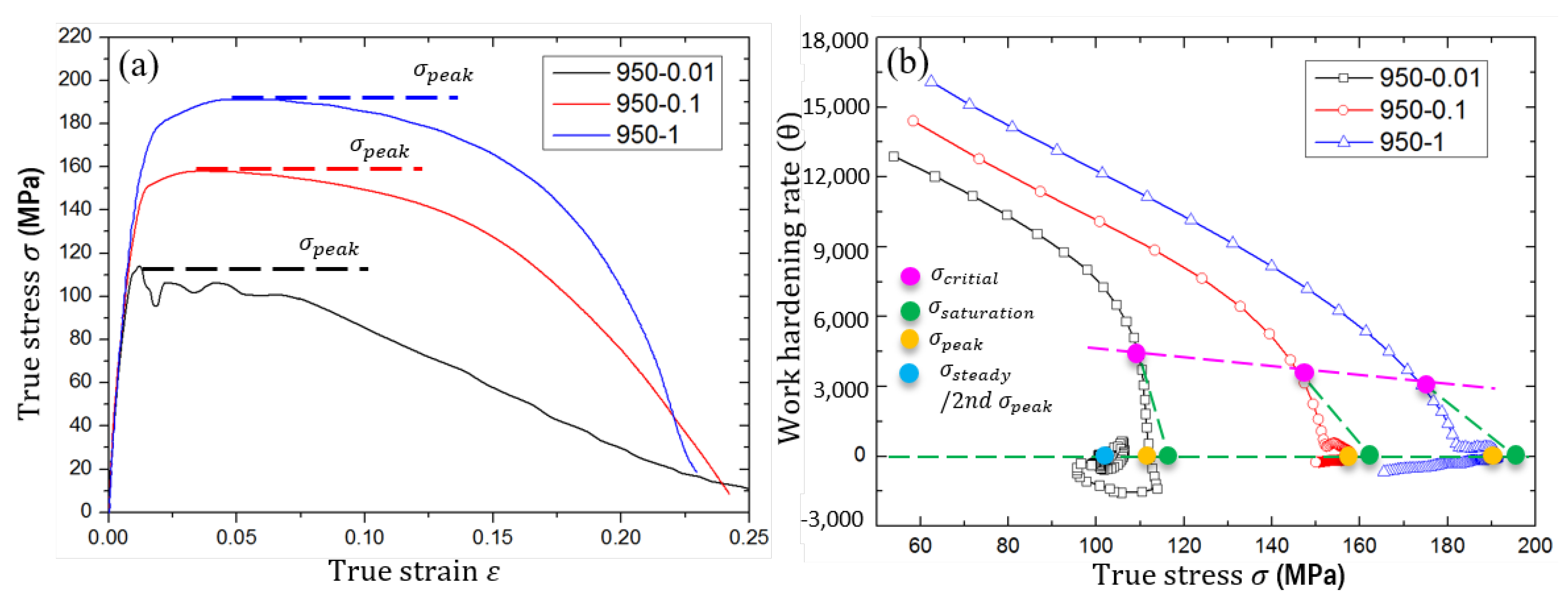
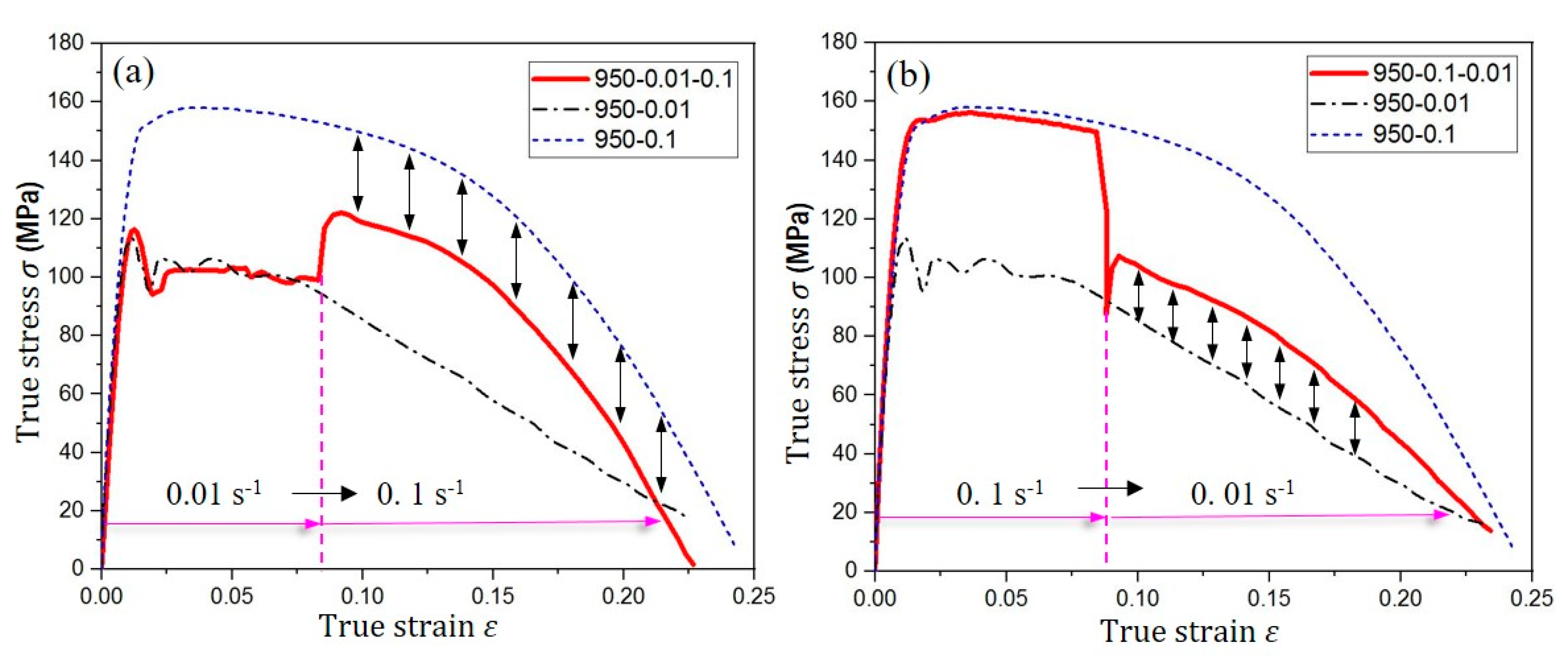
3.1. Hot Deformation Characteristics of the Bimetal Composite

In order to investigate the formability of 2205/AH36 BC, the hot tensile tests were performed to obtain the stress–strain curves of the bimetal composite specimens. The obtained stress–strain curves at the strain rate of 0.01 for different elevated temperatures are shown in Figure 4. It is noted that the working temperature has a great impact on the flow stress, decreasing with the increase in the imposed temperature, but has little influence on the elongation of the bimetal composite. The necking points at 1050–1250 °C are similar, except that the necking position at 950 °C is slightly forward. The reason is that the high dislocation mobility results in the increase in ductility at relatively higher temperatures [11]. The multiple peaks of the flow stress occur at all temperatures under the strain rate of 0.01 s−1, i.e., the flow stress shows several minor peaks after it reaches the highest peak ( σ p e a k ), which is attributed to the several independent cycles of the dynamic recrystallization (DRX) softening effect [30,31]. As the rearranged dislocation structures are the basis of nucleation in the DRX process, the relationship between the critical dislocation pile-up, which will trigger the occurrence of DRX, and the dislocation decrement during the deformation process determines whether the multiple peak phenomenon occurs [32]. In addition, the occurrence of DRX can increase the limit strains for the uniaxial and biaxial sides of the forming limit diagram [33], thereby assisting in improving the ductility and formability of the bimetal composite.
Except the working temperature, the strain rate is another factor which affects the formability of steels at elevated temperatures. The flow stress–strain curves of 2205/AH36 BC at 950 °C under the stain rates of 0.01, 0.1 and 1 s−1 are shown in Figure 5a. It is obvious that the peak flow stress increases with the increase in the working strain rate due to the two reasons: (i) the high strain rate increases the barriers of dislocation motion during the plastic deformation; (ii) there is no sufficient time for dislocation annihilation through the softening effect at the relatively high strain rate [34]. This will lead to the higher forming force and more difficult deformation of the bimetal composite when the imposed working strain rate is high in the forming process. During the deformation process, the magnitude of peak stress is related to the work hardening (WH) rate, and the flow stress increases sharply when the WH rate is higher than the softening rate induced by DRV at the initial small strain deformation stage [13,18]. An analysis of the WH rate is best performed on a differential basis, and the WH rate is expressed as [35]
θ = σ ϵ | ε ˙   , T =   σ i + 1 σ i ε i + 1 ε i | ε ˙   , T ( i = 1 ,   2 ,   3 )
where σ , ε , ε ˙ and T represent the flow stress, strain, strain rate and working temperature, respectively.
The relationship curves of WH rate versus flow stress at 950 °C under different strain rates are shown in Figure 5b. The critical stress for initiation of DRX ( σ c r i t i a l ) is obtained from the first inflection point in the θ σ curve, and the approximately linear segment is extrapolated to θ = 0 using the method of idealized curve [30,36], which is used to predict the saturation stress ( σ s a t u r a t i o n ) resulting from the DRV softening effect alone. The first intersection point of the θ σ curve and the horizontal line of θ = 0 represent the occurrence of peak stress ( σ p e a k ), and the second intersection of those lines means the occurrence of steady stress ( σ s t e a d y ) or the second peak stress. Apart from the effect of different strain rates on the flow stress, the change of strain rates during the deformation process has an influence on the flow behavior of the bimetal composite. Figure 6a,b illustrate two conditions of deformation conducted under transient loading conditions, in which the specimens of the bimetal composite were deformed at a constant temperature of 950 °C with the varied strain rate from 0.01 to 0.1 s−1 or from 0.1 to 0.01 s−1, respectively. In Figure 6a, it is found that the magnitude of flow stress after the change of strain rate from 0.01 to 0.1 s−1 is smaller than that of flow stress at the constant strain rate of 0.1 s−1, and the possible reason is that the specimen has experienced the DRX softening process of its first half of the low strain rate stage. On the contrary, in Figure 6b, the flow stress is higher after the jump of strain rate from 0.1 to 0.01 s−1 than that at the same strain rate of 0.1 s−1, due to the lack of a sufficient DRX softening effect at the front stage. Therefore, the flow stress of 2205/AH36 BC exhibits opposite characteristics at elevated temperatures when the material experiences the different transient loading conditions of the strain rate.
In order to describe the dependence of flow stress on the imposed working conditions, a constitutive model was developed to predict the deformation behavior of 2205/AH36 BC under different imposed conditions based on experimental stress–strain curves and it can be used to set the material properties of the bimetal composite in the numerical simulation of hot bending. The constitutive model presents the relationship between the flow stress of the bimetal composite and processing strain rates and temperatures, described as [37]
{ σ = σ p e a k ( 1 e Ωε )                                                                                             ( ε < ε c ) σ = σ p e a k                                                                                                                                       ( ε ε c )   σ p e a k = 78.62 × sinh 1 ( 0.000646 · Z 0.143 )                                                           if  Z    7.24158 × 10 25 Ω = 29732.6 · Z 0.0896 Z = ε ˙   exp ( 628900 R T )      
and
{ σ = σ p e a k ( 1 e Ωε )                                                                                                                                 ( ε < ε c )     σ = σ p e a k ( σ p e a k σ s t e a d y ) { 1 exp [ 1.06 ( ε ε c ε p ) 2.383 ] } ( ε ε c ) σ p e a k = 78.62 × sinh 1 ( 0.000646 · Z 0.143 )                                                                                                               σ s t e a d y = 78.62 × sinh 1 ( 0.00184 · Z 0.12 ) Ω = 29732.6 · Z 0.0896 ε p = 6.21 × 10 4 · Z 0.052 ε c = 4.968 × 10 5 · Z 0.052           Z = ε ˙   exp ( 628900 R T )                                                                               if  Z  <   7.24158 × 10 25  
where Ω denotes the softening coefficient, Z is the Zener–Hollomon parameter of 2205/AH36 BC, ε c represents the critical strain and ε p is the peak strain.

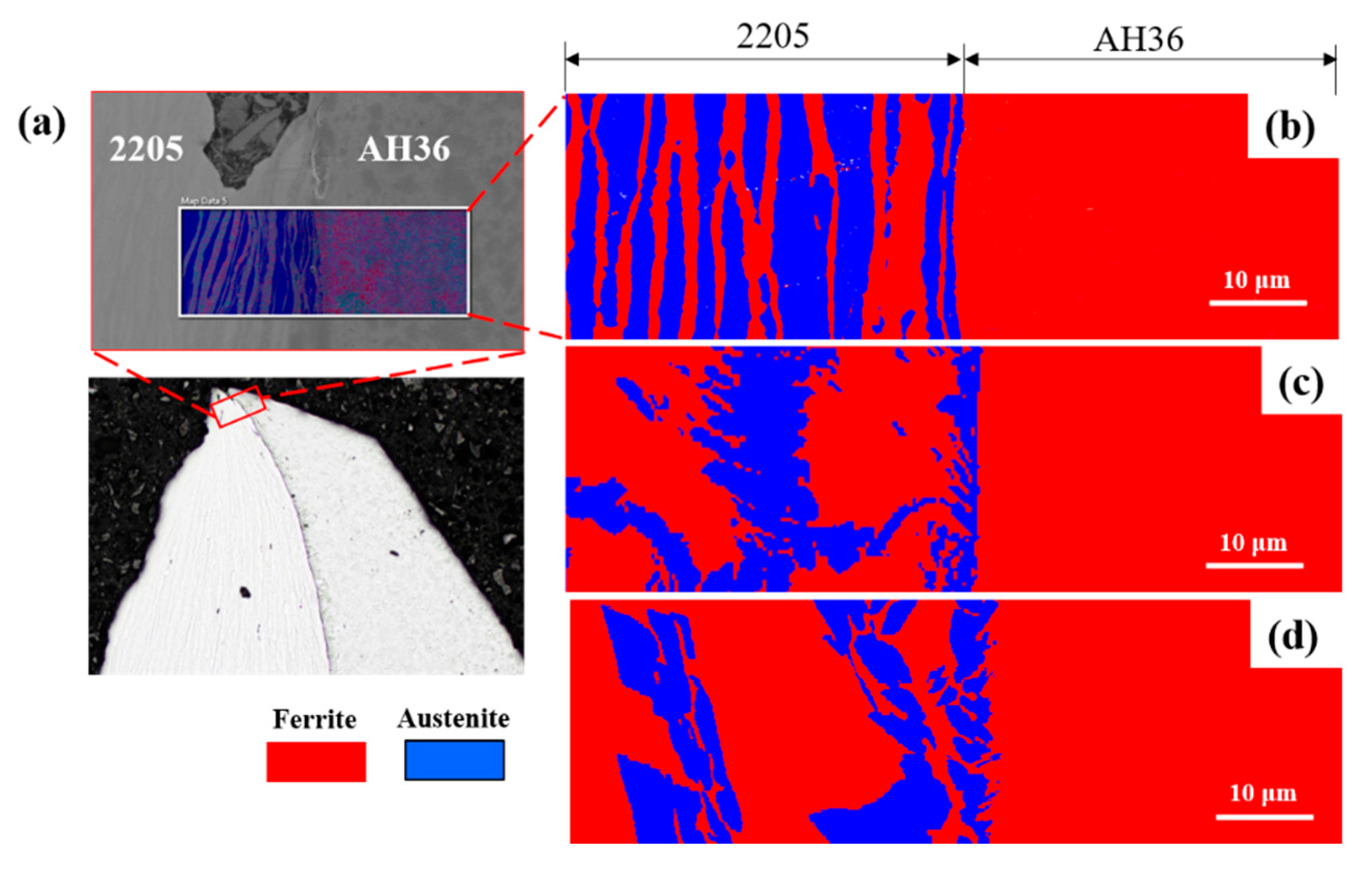
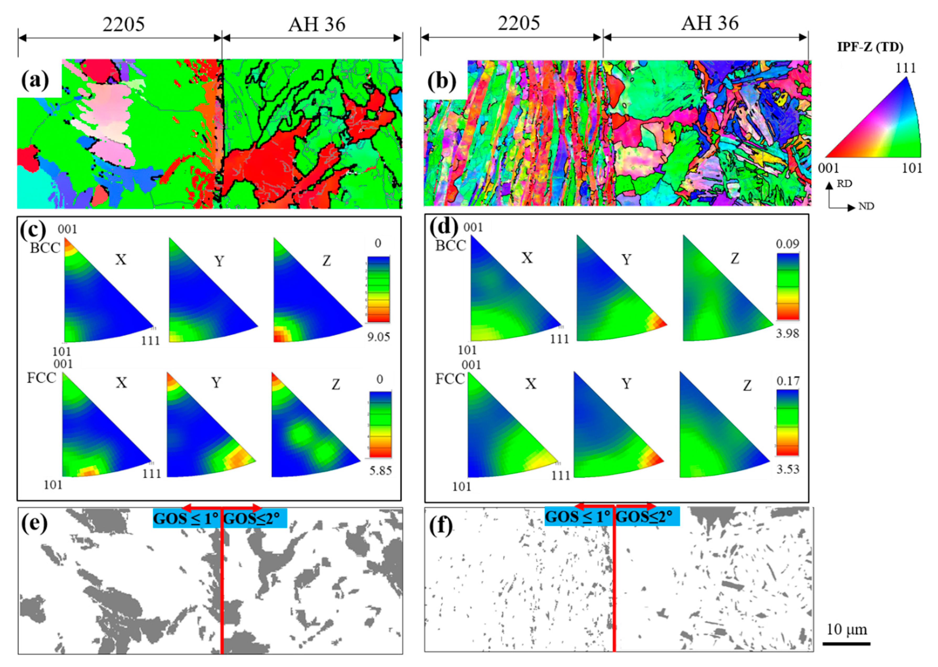
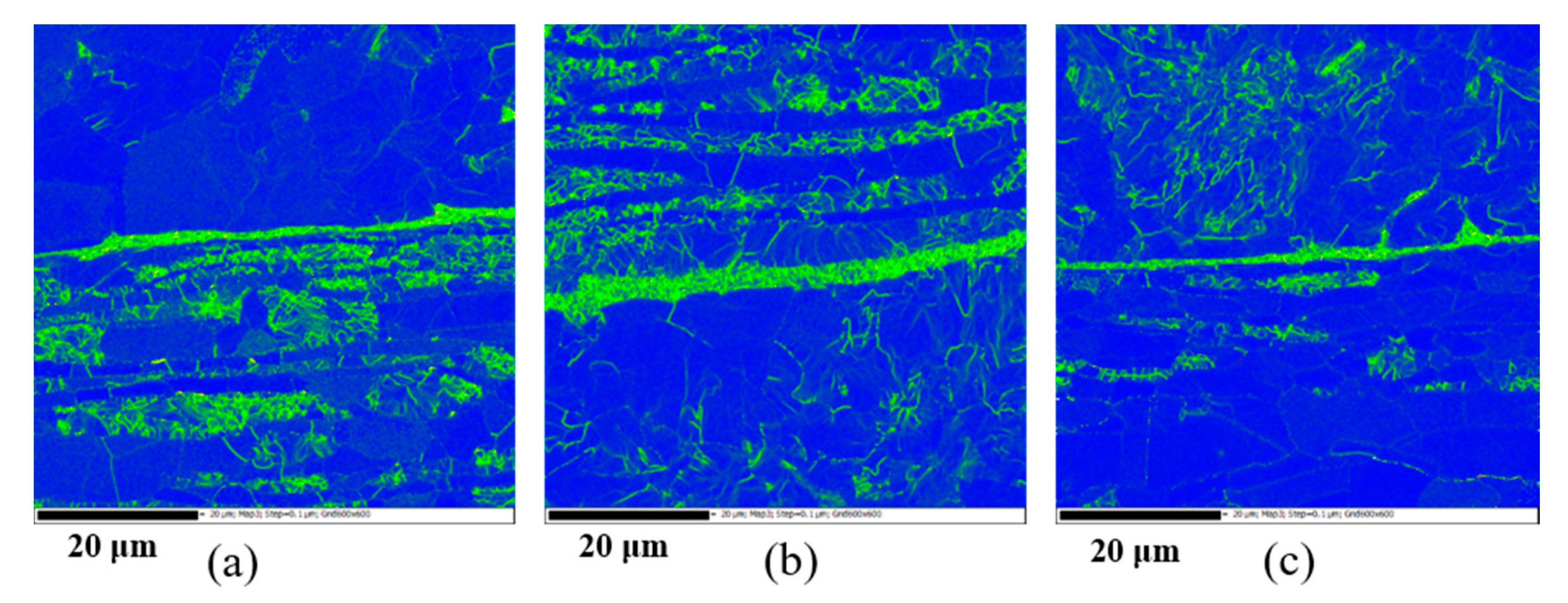
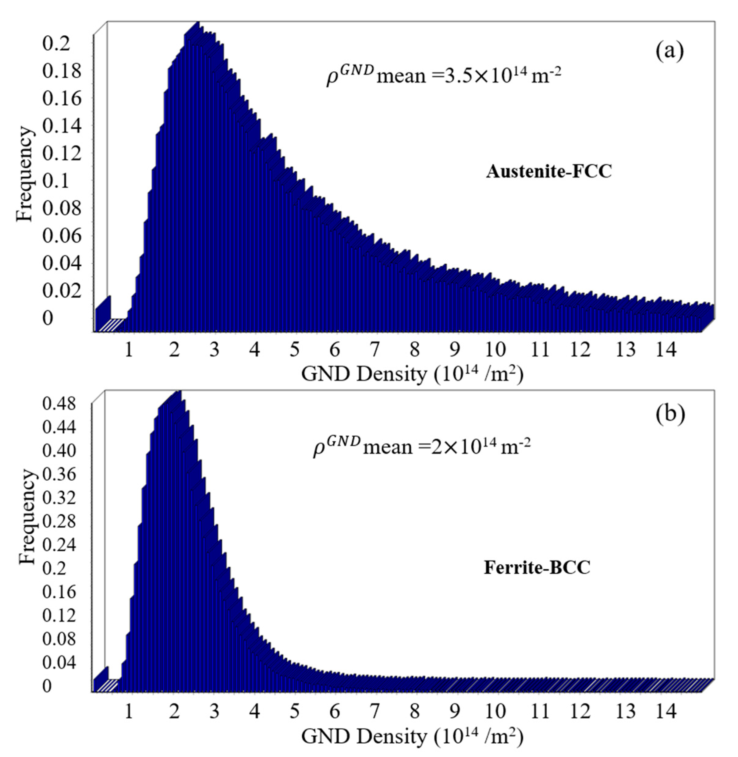
3.2. Microstructure Characterization after Tensile Deformation

EBSD maps in the fractured tip area were obtained to study the microstructure evolution mechanisms of the bimetal composite, as shown in Figure 7a. The phase maps of the received specimen and fractured specimens of 2205/AH36 BC tested at 950 and 1250 °C with the strain rate of 0.01 s−1 are shown in Figure 7b–d, respectively. The ferrite and austenite phases of the 2205 stainless steel layer grow together, respectively, and the alternating distribution of phase bands changes from dense to loose after the hot tensile tests. The volume fractions of the ferrite phase, obtained by the Oxford Instruments Channel-5 software, increase after hot tensile tests at 950 and 1250 °C with the strain rate of 0.01 s−1, reaching 63.3% and 61.3%, respectively, but the volume fractions of the austenite phase decrease from 54.8% to 36.7% and 38.7%, respectively. Except the phase evolution, the DRX softening mechanism is a main microstructure evolution of 2205/AH36 BC after the hot deformation process [32]. To partition DRXed grains from the unrecrystallized ones, a criterion that is often adopted based on local misorientation is the grain orientation spread (GOS) [38,39]. The orientation spread is defined as the misorientation angle between all the pixels in a grain, and GOS is the average orientation spread in the grain. According to Allian-Bonasso et al. [40], the GOS of any grain i is given as
GOS ( i ) = [ 1 J ( i ) ] j ω i j
where J ( i ) denotes the number of pixels in the grain i , and ω i j is the misorientations angle between the orientation of pixel j and the mean orientation of grain i . The high GOS value results from the deformation and distortion of grains, but the GOS value is low in the DRXed grains with free deformation [41]. The threshold value for GOS to distinguish the DRXed and deformed grains varied between 1° and 2° in various metals [42,43]. Due to the co-existing two constituent steels in 2205/AH36 BC, the grains with GOS ≤ 1° and GOS ≤ 2° for 2205 and AH36 steel layers are determined as recrystallized grains, respectively, resulting from the grain statistics of individual steel after the hot deformation. In addition, when the misorientations ( δ ) ≥ 2°, the grain or subgrain boundaries are identified in the microstructure, in which are the low-angle grain boundaries (LAGBs) with the 2° < δ < 15° misorientations and the high-angle grain boundaries (HAGBs) with the δ > 15° misorientations.
The typical shape of the flow curve at 950 °C with the strain rate of 0.1 s−1 shows a transition state between the DRV and DRX mechanisms, presented in our previous research [37], so that it is necessary to observe the microstructure evolution under its circumjacent hot working conditions. Under this circumstance, the inverse pole figure (IPF) and GOS maps of tip zones after hot tests at 950 °C with the strain rates of 0.01 and 1 s−1 are shown in Figure 8. In GOS maps (Figure 8e,f), the DRXed grains area is colored with gray, and the unrecrystallized region is colored with white. The partial area and interfacial area are basically recrystallized at 950 °C with the strain rate of 0.01 s−1 (Figure 8e), but the DRX degree is small at the relatively high strain rate of 1 s−1 (Figure 8f).

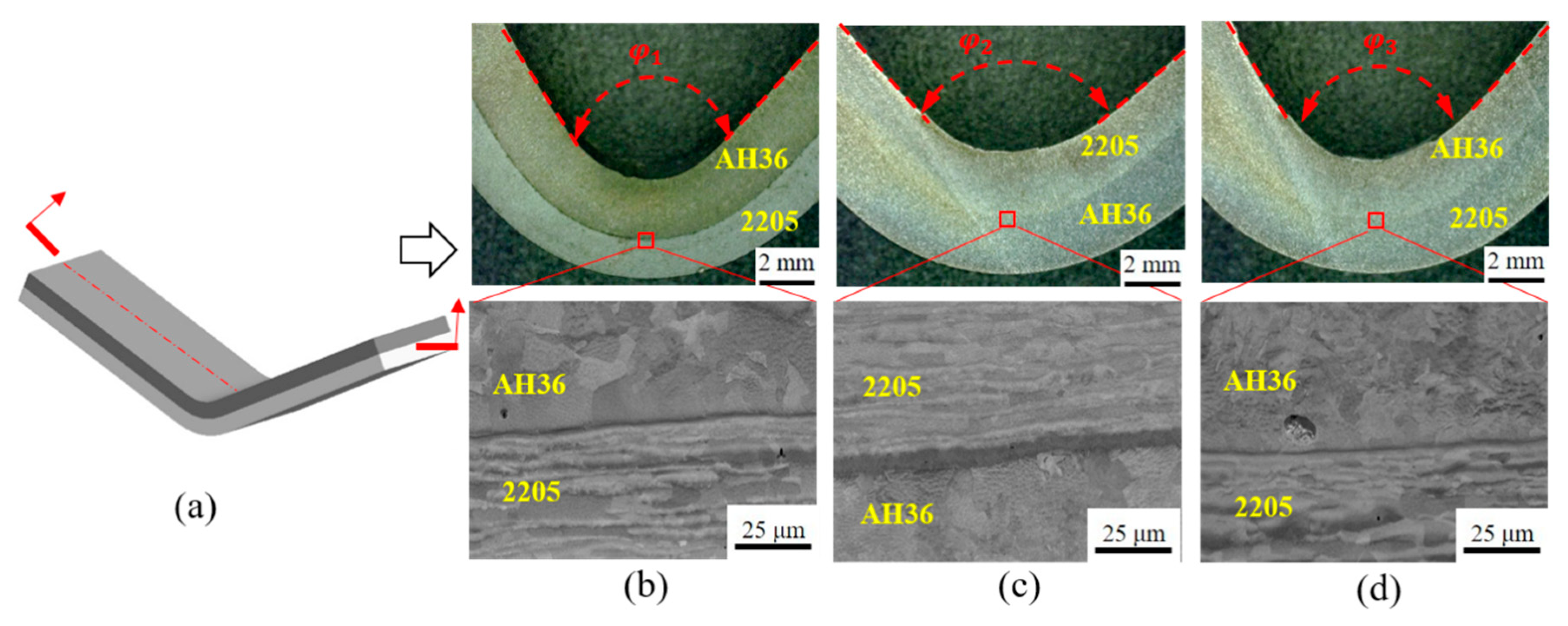
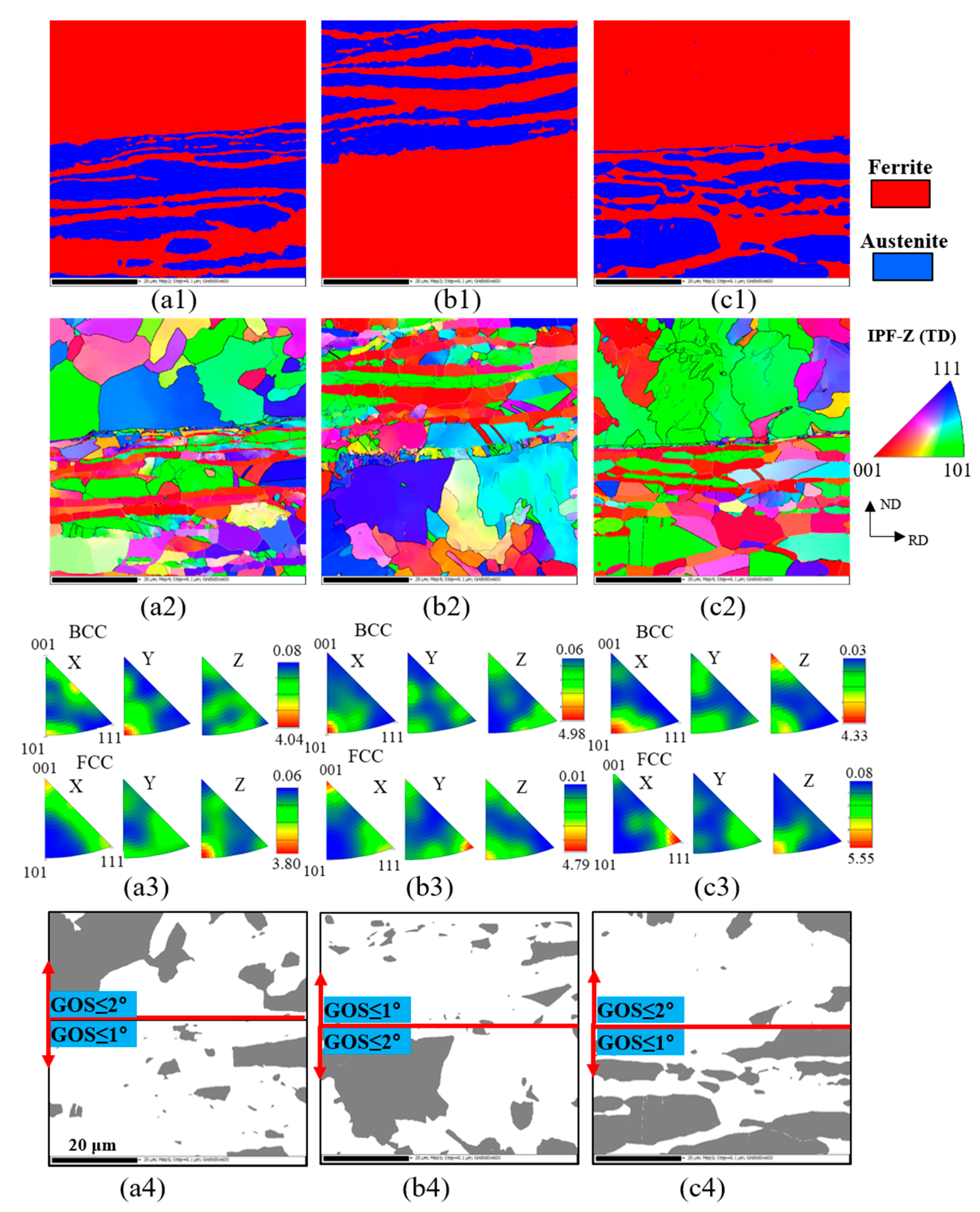
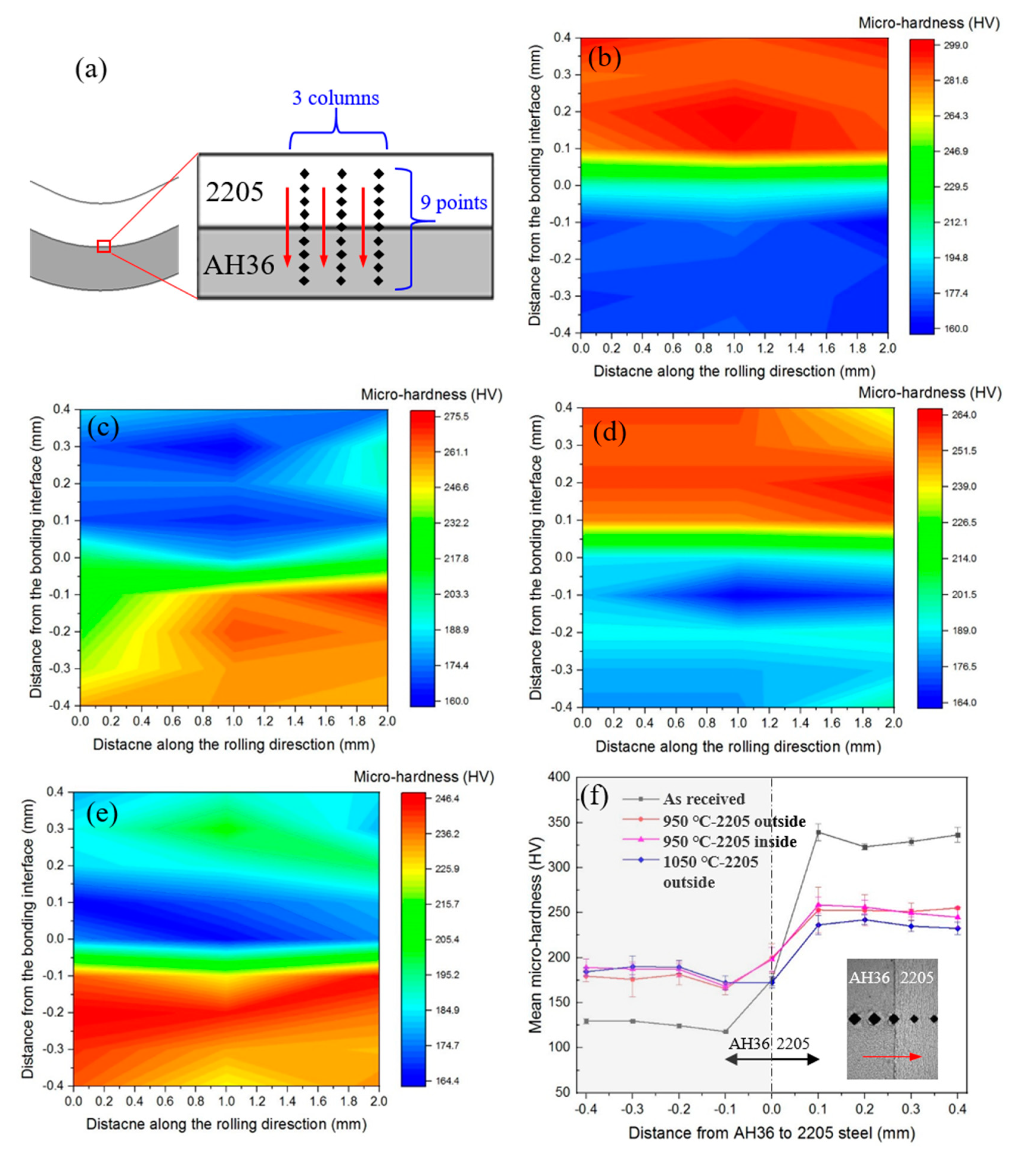
3.3. Properties and Microstructure after Hot Forming

According to the deformation characteristics of 2205/AH36 BC during hot tensile tests, it is noted that it has a good formability at elevated temperatures, and the imposed working temperatures and strain rates have a great influence on the material properties and microstructure evolution. The hot bending tests were conducted to further verify the feasibility of the hot forming of 2205/AH36 BC. Figure 9 shows the cross-section and SEM morphology of the bent parts after hot bending tests under different working conditions. The parts could be formed under those conditions without delamination and obvious cracks around the interface in the region of maximum deformation of all specimens. In addition, the bent angles of specimens are different when the relative positions of constitutive steel layers are opposite at the same working temperature (950 °C), i.e., the bent angle ( φ 1 ) of the 2205 steel layer outside is smaller than the angle ( φ 2 ) of the 2205 steel layer inside contacting the punch. The reason is that the relatively weak AH36 steel layer deforms easier when it is compressed by the punch compared with the 2205 steel layer, and this phenomenon has been reported in previous research at room temperature [29]. Moreover, the temperature has less effect on the bent angle of specimens when the layer stacking sequence is the same, i.e., the bent angle ( φ 1 ) at the bending temperature of 950 °C is similar to the bent angle ( φ 3 ) at the working temperature of 1050 °C.
The phase, IPF and GOS maps of deformed specimens around the interface marked with the red rectangle in Figure 9 were obtained by the EBSD technique after hot bending. There is no obvious change in the alternating phases of the 2205 steel layer at the imposed temperature of 950 °C (Figure 10(a1,b1)), even though the 2205 steel locating at different positions experienced opposite deformation states, i.e., in compression and in tension, respectively, but the ferrite and austenite phases begin to gradually merge together at the bending temperature of 1050 °C (Figure 10(c1)). Referring to IPF maps, the equiaxed grains without subgrains are dominant in the AH36 steel layer, but the grains of the 2205 steel layer keep the long shape with many subgrains at the temperature of 950 °C. On the contrary, the grains in the 2205 steel layer gradually grow into equiaxed ones, and some subgrains occur in the large-size grains of the AH36 steel layer. This indicates that the effect of the working temperature on the microstructure evolution is larger than that of the stacking sequence for the bimetal composite during the hot bending process. In order to delineate the DRXed area, the grains were analyzed based on GOS maps, which support the evolution trend of grains observed in IPF maps. According to the GOS maps, it is found that the DRXed area of the AH36 steel layer is larger than that of the 2205 steel layer after hot bending at 950 °C, but this trend is opposite for the bent specimen at 1050 °C.
Apart from the microstructure evolution of bent specimens, the micro-hardness tests based on the Matsuzawa automatic hardness test system were conducted on the deformed parts to evaluate the post-form mechanical properties of the as-formed specimens. The micro-hardness measurement scheme, micro-hardness cartography maps and comparison of the mean micro-hardness under different working conditions are shown in Figure 11, respectively. There are nine points for each column (three columns) used to obtain the micro-hardness value of specimens across the interface from the 2205 steel layer to the AH36 steel layer. The distribution of the micro-hardness value around the interface of deformed parts is not as uniform as that of the received specimen, due to the pile-up of dislocations and microstructure evolution after the hot bending deformation. Moreover, the micro-hardness values of the AH36 steel layer increase after the hot deformation under three working conditions compared to the received one, but this trend is opposite for the 2205 steel layer. The micro-hardness value of the 2205 steel layer of the deformed specimen is lowest at 1050 °C, which matches the phenomenon of the large area of DRXed grains in the 2205 steel layer, as shown in Figure 10(c4).

4. Discussion

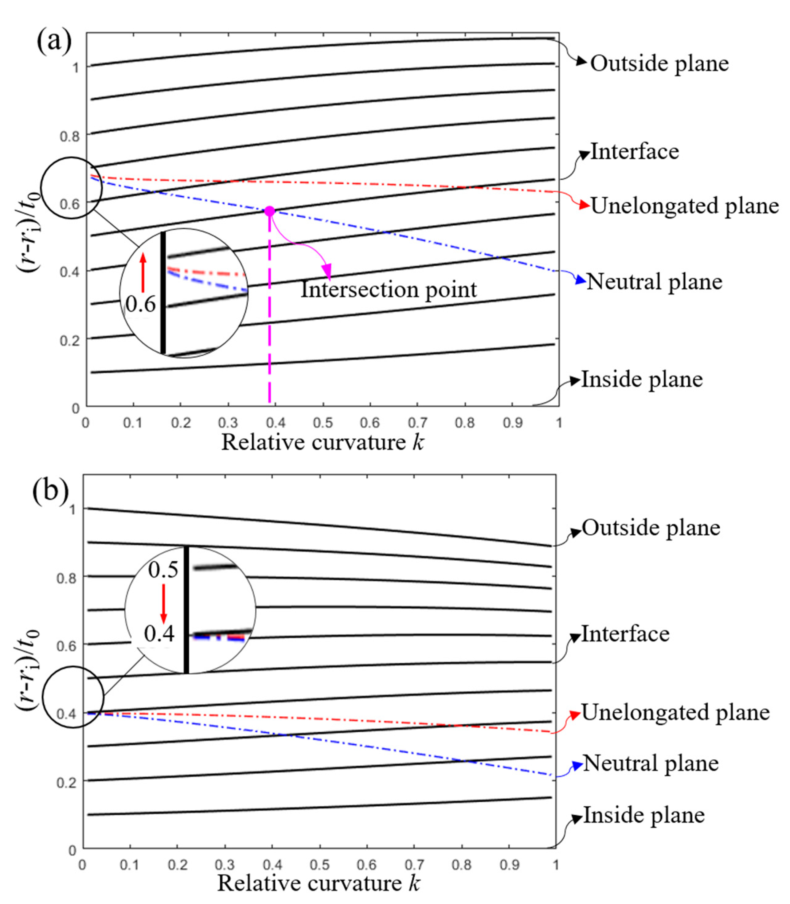
4.1. Effects of Working Conditions on Forming Force

The results of the microstructure evolution and micro-hardness of deformed parts under different imposed conditions were provided in the previous section, and it is also necessary to discuss the effects of working conditions on the macroscopic properties of specimens during the forming process, such as the forming force, which is an important reference for industrial production [6]. Although there is no obvious microstructure difference of post-form parts with the exchanged stacking sequence at the working temperature of 950 °C, as shown in Figure 10, the forming forces under these two conditions are different. The force magnitude is larger with the relatively stronger 2205 steel layer outside than that when the 2205 steel layer is positioned inside, as shown in Figure 12, and this phenomenon was reported by previous research at room temperature [6]. The possible reason is that the stronger 2205 steel layer is outside, in which most regions are under stretching and thinning conditions, so that more forming energy and forces are required during the hot bending process [44]. Moreover, the influence of the working temperature on the forming force is more significant. As shown in Figure 12, the loading force is very small when the imposed temperature is 1050 °C compared to those with the working temperature of 950 °C, and it even becomes zero before the punch reaches the setting deformation destination ( t ). This matches the trend that there is also a great stress gap between the working temperatures of 950 and 1050 °C at all strain rates in the hot tensile tests [37].
In addition, it is noted that the forming force experienced a second increase ( F ) in the later stage of the hot bending process at the working temperature of 950 °C with the outside 2205 steel layer. The reason is that the neutral plane passed the bonding interface of the bimetal composite during the bending process, resulting in the change of the deformation situation of two steel layers [29]. The neutral plane is defined as the critical plane of tensile and compressive zones with a bent beam or plate, so that the inner surface is in compression and the outer surface is in tension. The position of the neutral plane slowly approaches the inner radius (ri) with the increase in the relative curvature (κ). The non-dimensional parameter relative curvature κ = (ryri)/rm is regarded as a measure of bending extent, where ry is the outer radius and rm = (ri + ry)/2 is the current radius of the central plane. Figure 13 shows how the ten originally equidistant segments and particular planes move during the bending process under two conditions. The (rri)/t0 is determined as the relative position of any segment across the thickness of the plate, where r represents a particular segment radius and t0 is the original thickness of the plate. There is one intersection point between the bonding interface and neutral plane, as shown in Figure 13a, after which the forming force starts to increase again. On the contrary, there is no intersection point at the working temperature of 950 °C with the inside 2205 steel layer, as shown in Figure 13b, so that no obvious second increase in the forming force can be observed under this working situation.

4.2. Interfacial Heterogeneity under Different Hot Forming Conditions

Compared with a single metal or alloy, 2205/AH36 BC has two different metals and a unique bonding interface. The heterogeneity in grain size, strength, texture and softening mechanism between the 2205 and AH36 steel layers makes them mechanically incompatible during the hot forming process, which may result in an inconsistent microstructure evolution across the interface, affecting the mechanical properties of formed parts. As the microstructure heterogeneity is related to the accumulation of geometrically necessary dislocations (GNDs) during the plastic deformation [45], it is necessary to investigate the accumulation of GND density after the hot deformation near the interface. The calculation method of GND was proposed by previous research [32], and Figure 14 shows the GND density distribution mapping around the interface under different situations. It is noted that the pile-up of GND mainly occurs in the austenite phase of the 2205 steel layer with the face centered cubic (FCC) structure at the forming temperature of 950 °C, and the reason is that the annihilation of dislocations mainly occurred in the co-existing softer ferrite phase with the body centered cubic (BCC) structure during the hot deformation process. The mean value and statistical distributions of GND density are shown in Figure 15, respectively, for the bent specimens at the working temperature of 950 °C with the outside 2205 steel layer. It is found that the average value of GND in the austenite phase is higher than that in the ferrite phase. However, this phenomenon is not that obvious at the working temperature of 1050 °C, due to the occurrence of sufficient DRX softening effects, matching the trend of the GOS map in Figure 10(c4).
Moreover, the high accumulation of GND density around the interface was observed under all conditions after the hot deformation. There could be two reasons for this phenomenon: (i) some small cracks or other defects, as a result of the hot rolling process, are prone to form on the interface of the bimetal composite. Those defects could act as the dislocation source to develop the high pile-up of GND density during the hot forming process [46]; (ii) the stress states of the deformed zone, i.e., in compression or in tension, are different around the interface between the two steel layers, generating the different directions of material flow and equivalent plastic strain, as shown in Figure 16, and two different steels may affect each other at the interface, resulting in the shear stress field [32].

5. Conclusions

The deformation characteristics and microstructure evolution of hot-rolled 2205/AH36 BC during the hot tensile and hot forming processes were investigated in this study. The main conclusions of this research are drawn as follows:
(1) The multiple-peak flow stress of 2205/AH36 BC occurs at a relatively low strain rate, and the peak flow stress increases with the increase in the working strain rate. When the 2205/AH36 BC experienced different transient loading conditions of the strain rate, the flow stress of 2205/AH36 BC exhibits opposite characteristics at elevated temperatures.
(2) Phase and GOS maps of specimens after hot tensile and forming tests were obtained to study the microstructure evolution, respectively. It is found that the effect of the working temperature on microstructure evolution is larger than that of the stacking sequence for 2205/AH36 BC during the hot bending process.
(3) The GND density of the austenite phase in the 2205 steel layer shows a high level at the forming temperature of 950 °C. The considerable GND accumulation occurs around the interface of 2205/AH36 BC under all imposed working conditions after the hot bending process, due to the interfacial micro-defects and complex stress states.

Author Contributions

Conceptualization, Z.L. and Z.J.; methodology, Z.L., F.J., Y.L. and H.X.; software, F.J.; validation, X.Y.; formal analysis, Z.L.; investigation, Z.L.; resources, S.J.; data curation, H.X. and Y.L.; writing—original draft preparation, Z.L.; writing—review and editing, H.X. and Z.J.; supervision, S.J. and Z.J.; project administration, X.Y. and S.J.; funding acquisition, S.J. All authors have read and agreed to the published version of the manuscript.

Funding

This research received financial support from Baosteel-Australia Joint Research and Development Centre (BAJC) under project of BA-19011.

Acknowledgments

The first author is greatly thankful for the scholarship support (IPTA) from University of Wollongong and scholarship support from China Scholarship Council (CSC). The authors wish to gratefully acknowledge the financial support from Baosteel-Australia Joint Research and Development Centre (BAJC).

Conflicts of Interest

The authors declare no conflict of interest.

References

  1. Xu, J.; Gao, X.; Jiang, Z.; Wei, D.; Jiao, S. Microstructure and hot deformation behaviour of high-carbon steel/low-carbon steel bimetal prepared by centrifugal composite casting. Int. J. Adv. Manuf. Technol. 2016, 86, 817–827. [Google Scholar] [CrossRef]
  2. Dhib, Z.; Guermazi, N.; Ktari, A.; Gasperini, M.; Haddar, N. Mechanical bonding properties and interfacial morphologies ofB austenitic stainless steel clad plates. Mater. Sci. Eng. A 2017, 696, 374–386. [Google Scholar] [CrossRef]
  3. Khodadad Motarjemi, A.; KoC’ak, M.; Ventzke, V. Mechanical and fracture characterization of a bi-material steel plate. Int. J. Press. Vessel. Pip. 2002, 79, 181–191. [Google Scholar] [CrossRef]
  4. Bataev, I.A.; Lazurenko, D.V.; Tanaka, S.; Hokamoto, K.; Bataev, A.A.; Guo, Y.; Jorge, A.M. High cooling rates and metastable phases at the interfaces of explosively welded materials. Acta Mater. 2017, 135, 277–289. [Google Scholar] [CrossRef]
  5. Li, Z.; Zhao, J.; Wu, H.; Jia, F.; Yao, Y.; Zhang, Q.; Jiao, S.; Jiang, Z. Experimental investigation on the mechanical and tribological coupled behaviour of bimetal composite under different states. Surf. Topogr. Metrol. Prop. 2019, 7, 025015. [Google Scholar] [CrossRef]
  6. Li, Z.; Zhao, J.; Jia, F.; Zhang, Q.; Liang, X.; Jiao, S.; Jiang, Z. Numerical and experimental investigation on the forming behaviour of stainless/carbon steel bimetal composite. Int. J. Adv. Manuf. Technol. 2019, 101, 1075–1083. [Google Scholar] [CrossRef]
  7. Rozumek, D.; Kwiatkowski, G. The Influence of Heat Treatment Parameters on the Cracks Growth under Cyclic Bending in St-Ti Clad Obtained by Explosive Welding. Metals 2019, 9, 338. [Google Scholar] [CrossRef] [Green Version]
  8. Zhao, J.; Jiang, Z.; Lee, C.S. Enhancing impact fracture toughness and tensile properties of a microalloyed cast steel by hot forging and post-forging heat treatment processes. Mater. Des. 2013, 47, 227–233. [Google Scholar] [CrossRef] [Green Version]
  9. Wei, D.B.; Huang, J.X.; Zhang, A.W.; Jiang, Z.Y.; Tieu, A.K.; Shi, X.; Jiao, S.H.; Qu, X.Y. Study on the oxidation of stainless steels 304 and 304L in humid air and the friction during hot rolling. Wear 2009, 267, 1741–1745. [Google Scholar] [CrossRef]
  10. Zhu, H.T.; Jiang, Z.Y.; Tieu, A.K.; Wang, G.D. A fuzzy algorithm for flatness control in hot strip mill. J. Mater. Process. Technol. 2003, 140, 123–128. [Google Scholar] [CrossRef]
  11. Kopec, M.; Wang, K.; Politis, D.J.; Wang, Y.; Wang, L.; Lin, J. Formability and microstructure evolution mechanisms of Ti6Al4V alloy during a novel hot stamping process. Mater. Sci. Eng. A 2018, 719, 72–81. [Google Scholar] [CrossRef] [Green Version]
  12. Cheng, X.; Jiang, Z.; Wei, D.; Zhao, J.; Monaghan, B.J.; Longbottom, R.J.; Jiang, L. Characteristics of oxide scale formed on ferritic stainless steels in simulated reheating atmosphere. Surf. Coat. Technol. 2014, 258, 257–267. [Google Scholar] [CrossRef] [Green Version]
  13. Lin, Y.C.; Chen, X.-M. A critical review of experimental results and constitutive descriptions for metals and alloys in hot working. Mater. Des. 2011, 32, 1733–1759. [Google Scholar] [CrossRef]
  14. Gao, P.; Zhan, M.; Fan, X.; Lei, Z.; Cai, Y. Hot deformation behavior and microstructure evolution of TA15 titanium alloy with nonuniform microstructure. Mater. Sci. Eng. A 2017, 689, 243–251. [Google Scholar] [CrossRef]
  15. Zhang, Y.; Chai, Z.; Volinsky, A.A.; Tian, B.; Sun, H.; Liu, P.; Liu, Y. Processing maps for the Cu-Cr-Zr-Y alloy hot deformation behavior. Mater. Sci. Eng. A 2016, 662, 320–329. [Google Scholar] [CrossRef] [Green Version]
  16. Lin, Y.C.; Chen, M.-S.; Zhong, J. Constitutive modeling for elevated temperature flow behavior of 42CrMo steel. Comput. Mater. Sci. 2008, 42, 470–477. [Google Scholar] [CrossRef]
  17. Lin, Y.C.; Chen, M.-S.; Zhong, J. Effect of temperature and strain rate on the compressive deformation behavior of 42CrMo steel. J. Mater. Process. Technol. 2008, 205, 308–315. [Google Scholar] [CrossRef]
  18. Lin, Y.C.; Chen, M.-S.; Zhong, J. Prediction of 42CrMo steel flow stress at high temperature and strain rate. Mech. Res. Commun. 2008, 35, 142–150. [Google Scholar] [CrossRef]
  19. Gao, X.; Jiang, Z.; Wei, D.; Jiao, S.; Chen, D.; Xu, J.; Zhang, X.; Gong, D. Effects of temperature and strain rate on microstructure and mechanical properties of high chromium cast iron/low carbon steel bimetal prepared by hot diffusion-compression bonding. Mater. Des. 2014, 63, 650–657. [Google Scholar] [CrossRef] [Green Version]
  20. Cheng, Y.Q.; Zhang, H.; Chen, Z.H.; Xian, K.F. Flow stress equation of AZ31 magnesium alloy sheet during warm tensile deformation. J. Mater. Process. Technol. 2008, 208, 29–34. [Google Scholar] [CrossRef]
  21. Li, J.; Wang, B.; Huang, H.; Fang, S.; Chen, P.; Zhao, J.; Qin, Y. Behaviour and constitutive modelling of ductile damage of Ti-6Al-1.5Cr-2.5Mo-0.5Fe-0.3Si alloy under hot tensile deformation. J. Alloy. Compd. 2019, 780, 284–292. [Google Scholar] [CrossRef] [Green Version]
  22. Deng, J.; Lin, Y.C.; Li, S.-S.; Chen, J.; Ding, Y. Hot tensile deformation and fracture behaviors of AZ31 magnesium alloy. Mater. Des. 2013, 49, 209–219. [Google Scholar] [CrossRef]
  23. Huang, Y.-C.; Lin, Y.C.; Deng, J.; Liu, G.; Chen, M.-S. Hot tensile deformation behaviors and constitutive model of 42CrMo steel. Mater. Des. 2014, 53, 349–356. [Google Scholar] [CrossRef]
  24. Zhang, D.-N.; Shangguan, Q.-Q.; Xie, C.-J.; Liu, F. A modified Johnson–Cook model of dynamic tensile behaviors for 7075-T6 aluminum alloy. J. Alloy. Compd. 2015, 619, 186–194. [Google Scholar] [CrossRef]
  25. Jiang, Z.Y.; Tieu, A.K. A simulation of three-dimensional metal rolling processes by rigid–plastic finite element method. J. Mater. Process. Technol. 2001, 112, 144–151. [Google Scholar] [CrossRef]
  26. Zhang, X.M.; Jiang, Z.Y.; Tieu, A.K.; Liu, X.H.; Wang, G.D. Numerical modelling of the thermal deformation of CVC roll in hot strip rolling. J. Mater. Process. Technol. 2002, 130–131, 219–223. [Google Scholar] [CrossRef]
  27. Tieu, A.K.; Jiang, Z.Y.; Lu, C. A 3D finite element analysis of the hot rolling of strip with lubrication. J. Mater. Process. Technol. 2002, 125–126, 638–644. [Google Scholar] [CrossRef]
  28. Jiang, Z.Y.; Liu, X.L.; Liu, X.H.; Wang, G.D. Analysis of ribbed-strip rolling by rigid-viscoplastic FEM. Int. J. Mech. Sci. 2000, 42, 693–703. [Google Scholar] [CrossRef]
  29. Li, Z.; Zhao, J.; Jia, F.; Zhang, Q.; Liang, X.; Jiao, S.; Jiang, Z. Analysis of bending characteristics of bimetal steel composite. Int. J. Mech. Sci. 2018, 148, 272–283. [Google Scholar] [CrossRef]
  30. Cheng, L.; Xue, X.; Tang, B.; Kou, H.; Li, J. Flow characteristics and constitutive modeling for elevated temperature deformation of a high Nb containing TiAl alloy. Intermetallics 2014, 49, 23–28. [Google Scholar] [CrossRef]
  31. Tan, K.; Li, J.; Guan, Z.; Yang, J.; Shu, J. The identification of dynamic recrystallization and constitutive modeling during hot deformation of Ti55511 titanium alloy. Mater. Des. 2015, 84, 204–211. [Google Scholar] [CrossRef]
  32. Li, Z.; Zhao, J.; Jia, F.; Lu, Y.; Liang, X.; Yuan, X.; Jiao, S.; Zhou, C.; Jiang, Z. Hot deformation behaviour and interfacial characteristics of bimetal composite at elevated temperatures. Intermetallics 2020, 125, 106893. [Google Scholar] [CrossRef]
  33. Nagra, J.S.; Brahme, A.; Lévesque, J.; Mishra, R.; Lebensohn, R.A.; Inal, K. A new micromechanics based full field numerical framework to simulate the effects of dynamic recrystallization on the formability of HCP metals. Int. J. Plast. 2020, 125, 210–234. [Google Scholar] [CrossRef]
  34. Wang, W.; Ma, Y.; Yang, M.; Jiang, P.; Yuan, F.; Wu, X. Strain Rate Effect on Tensile Behavior for a High Specific Strength Steel: From Quasi-Static to Intermediate Strain Rates. Metals 2018, 8, 11. [Google Scholar] [CrossRef] [Green Version]
  35. Dong, D.; Chen, F.; Cui, Z. A physically-based constitutive model for SA508-III steel: Modeling and experimental verification. Mater. Sci. Eng. A 2015, 634, 103–115. [Google Scholar] [CrossRef]
  36. Poliak, E.I.; Jonas, J.J. A one-parameter approach to determining the critical conditions for the initiation of dynamic recrystallization. Acta Mater. 1996, 44, 127–136. [Google Scholar] [CrossRef]
  37. Li, Z.; Zhao, J.; Jia, F.; Lu, Y.; Zhang, Q.; Jiao, S.; Jiang, Z. Analysis of flow behaviour and strain partitioning mechanism of bimetal composite under hot tensile conditions. Int. J. Mech. Sci. 2020, 169, 105317. [Google Scholar] [CrossRef]
  38. Rout, M.; Ranjan, R.; Pal, S.K.; Singh, S.B. EBSD study of microstructure evolution during axisymmetric hot compression of 304LN stainless steel. Mater. Sci. Eng. A 2018, 711, 378–388. [Google Scholar] [CrossRef]
  39. Kumar, S.; Samantaray, D.; Aashranth, B.; Keskar, N.; Davinci, M.A.; Borah, U.; Srivastava, D.; Bhaduri, A.K. Dependency of rate sensitive DRX behaviour on interstitial content of a Fe-Cr-Ni-Mo alloy. Mater. Sci. Eng. A 2019, 743, 148–158. [Google Scholar] [CrossRef]
  40. Allain-Bonasso, N.; Wagner, F.; Berbenni, S.; Field, D.P. A study of the heterogeneity of plastic deformation in IF steel by EBSD. Mater. Sci. Eng. A 2012, 548, 56–63. [Google Scholar] [CrossRef]
  41. Hadadzadeh, A.; Mokdad, F.; Wells, M.A.; Chen, D.L. A new grain orientation spread approach to analyze the dynamic recrystallization behavior of a cast-homogenized Mg-Zn-Zr alloy using electron backscattered diffraction. Mater. Sci. Eng. A 2018, 709, 285–289. [Google Scholar] [CrossRef]
  42. Prithiv, T.S.; Bhuyan, P.; Pradhan, S.K.; Subramanya Sarma, V.; Mandal, S. A critical evaluation on efficacy of recrystallization vs. strain induced boundary migration in achieving grain boundary engineered microstructure in a Ni-base superalloy. Acta Mater. 2018, 146, 187–201. [Google Scholar] [CrossRef]
  43. Yin, X.-Q.; Park, C.-H.; Li, Y.-F.; Ye, W.-J.; Zuo, Y.-T.; Lee, S.-W.; Yeom, J.-T.; Mi, X.-J. Mechanism of continuous dynamic recrystallization in a 50Ti-47Ni-3Fe shape memory alloy during hot compressive deformation. J. Alloy. Compd. 2017, 693, 426–431. [Google Scholar] [CrossRef]
  44. Yilamu, K.; Hino, R.; Hamasaki, H.; Yoshida, F. Air bending and springback of stainless steel clad aluminum sheet. J. Mater. Process. Technol. 2010, 210, 272–278. [Google Scholar] [CrossRef]
  45. He, J.; Ma, Y.; Yan, D.; Jiao, S.; Yuan, F.; Wu, X. Improving ductility by increasing fraction of interfacial zone in low C steel/304 SS laminates. Mater. Sci. Eng. A 2018, 726, 288–297. [Google Scholar] [CrossRef] [Green Version]
  46. Mara, N.A.; Beyerlein, I.J. Review: Effect of bimetal interface structure on the mechanical behavior of Cu–Nb fcc–bcc nanolayered composites. J. Mater. Sci. 2014, 49, 6497–6516. [Google Scholar] [CrossRef]
Figure 1. (a) Schematic illustration of the hot-rolled 2205/AH36 bimetal composite (BC), and (b) the observed metallography of 2205/AH36 BC.
Metals 10 01375 g001
Figure 2. (a) Dog bone-shaped tensile specimens of 2205/AH36 BC, (b) the schematic diagram of hot tensile test installation and (c) the test simulator assembled with a tensile specimen.
Metals 10 01375 g002
Figure 3. (a) Schematic diagram of hot bending setup, and (b) the test simulator assembled with a bending specimen.
Metals 10 01375 g003
Figure 4. Stress–strain curves of 2205/AH36 BC at the range of 950–1250 °C with the strain rate of 0.01 s−1.
Metals 10 01375 g004
Figure 5. (a) Stress–strain curves of 2205/AH36 BC, and (b) relationship curves of work hardening rate versus flow stress at the range of 0.01 s−1–1 s−1 with the temperature of 950 °C.
Metals 10 01375 g005
Figure 6. (a) The stress–strain curves with the strain rates of 0.01 and 0.1 s−1 and changing from 0.01 to 0.1 s−1 at 950 °C, and (b) the stress–strain curves with the strain rates of 0.01 and 0.1 s−1 and changing from 0.1 to 0.01 s−1 at 950 °C.
Metals 10 01375 g006
Figure 7. (a) The observed zone after tests, and the phase maps: (b) as received, (c) at 950 °C–0.01 s−1 and (d) at 1250 °C–0.01 s−1.
Metals 10 01375 g007
Figure 8. Orientation map inverse pole figure (IPF)-Z direction, IPF and grain orientation spread (GOS) maps of tip zones at 950 °C–0.01 s−1: (a,c and e), and at 950 °C–1 s−1: (b,d and f). LAGBs = gray, HAGBs = black.
Metals 10 01375 g008
Figure 9. (a) The bent model of 2205/AH36 BC, and the SEM morphology of the bent mid-section, (b) at 950 °C with the outside 2205 steel layer, (c) at 950 °C with the inside 2205 steel layer and (d) at 1050 °C with the outside 2205 steel layer.
Metals 10 01375 g009
Figure 10. The phase, orientation map IPF-Z direction, IPF and GOS maps of specimens after hot bending: (a1–a4) at 950 °C with the outside 2205 steel layer, (b1b4) at 950 °C with the inside 2205 steel layer and (c1c4) at 1050 °C with the outside 2205 steel layer. LAGBs = gray, HAGBs = black.
Metals 10 01375 g010
Figure 11. (a) Micro-hardness measurement scheme, (be) micro-hardness cartography maps of the as-received specimen, and specimens after hot bending at 950 °C with the outside 2205 layer, 950 °C with the inside 2205 layer and 1050 °C with the outside 2205 layer, and (f) comparison of the mean micro-hardness under different states.
Metals 10 01375 g011
Figure 12. The loading force of specimens under different forming conditions.
Metals 10 01375 g012
Figure 13. Position distributions of each segment with the increasing relative curvature at the hot working temperature of 950 °C: (a) with the outside 2205 steel layer, and (b) with the inside 2205 steel layer.
Metals 10 01375 g013
Figure 14. Images of geometrically necessary dislocation (GND) density mapping of specimens after hot bending: (a) at 950 °C with the outside 2205 steel layer, (b) at 950 °C with the inside 2205 steel layer and (c) at 1050 °C with the outside 2205 steel layer.
Metals 10 01375 g014
Figure 15. (a) Statistical distributions of GND density in the austenite phase, and (b) statistical distributions of GND density in the ferrite phase after hot bending at the working temperature of 950 °C with the outside 2205 steel layer.
Metals 10 01375 g015
Figure 16. (a) The flow directions of different steel layers around the interface during the hot bending process, and (b) the distribution of the equivalent plastic strain of the bent specimen along the rolling direction.
Metals 10 01375 g016
Publisher’s Note: MDPI stays neutral with regard to jurisdictional claims in published maps and institutional affiliations.

