Application of Reference Voltage Control Method of the Generator Using a Neural Network in Variable Speed Synchronous Generation System of DC Distribution for Ships


Abstract
:1. Introduction
1.1. Background
1.2. Current Issue
2. Materials and Methods
2.1. Necessity of Reference Voltage Control of Variable Speed Generator Engine
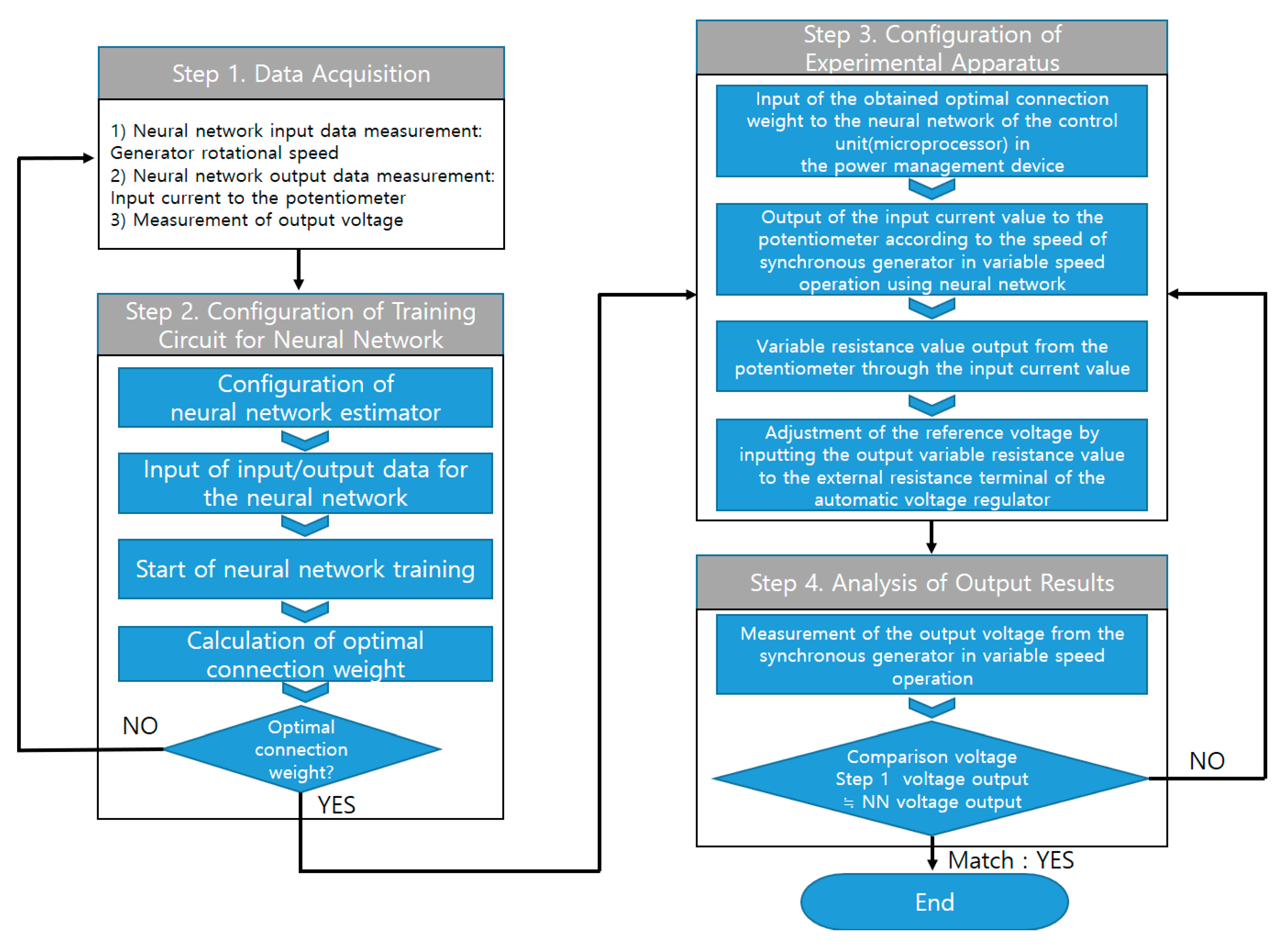
2.2. Methodology
2.2.1. Step 1: Data Acquisition
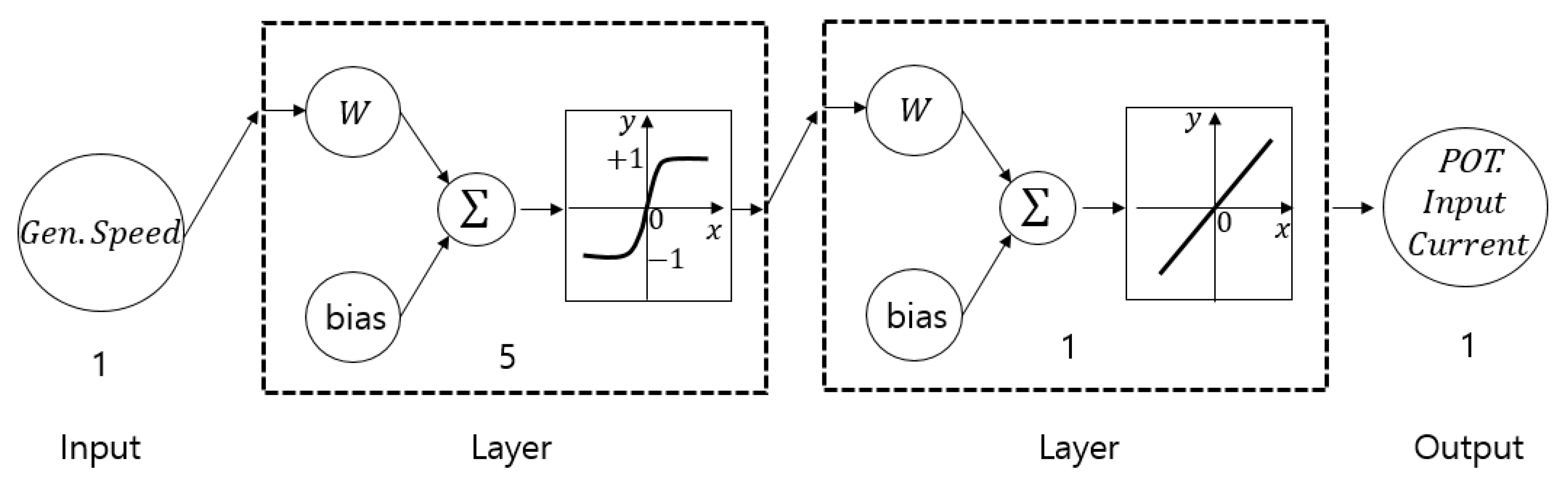
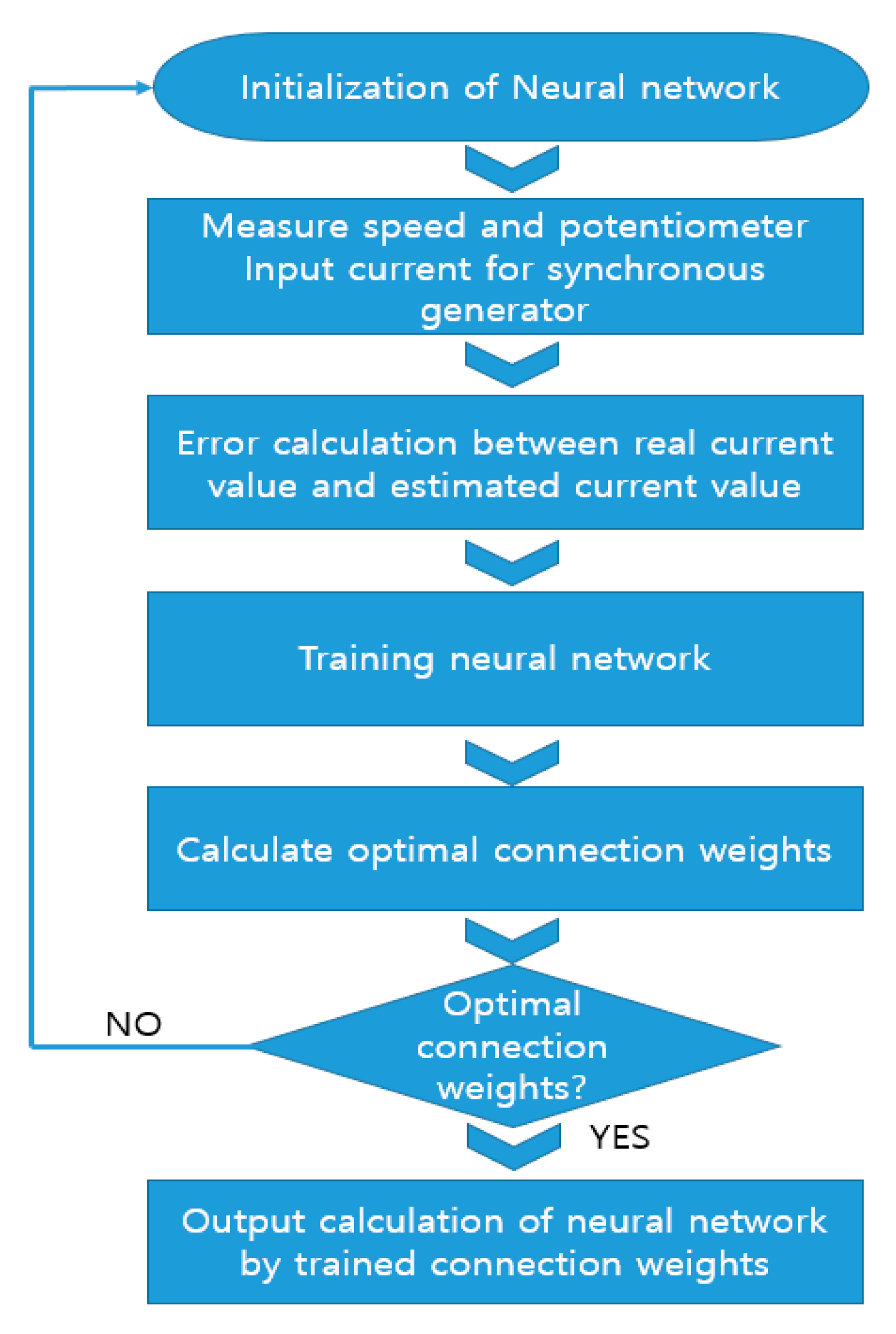
2.2.2. Step 2: Training Configuration for Neural Network
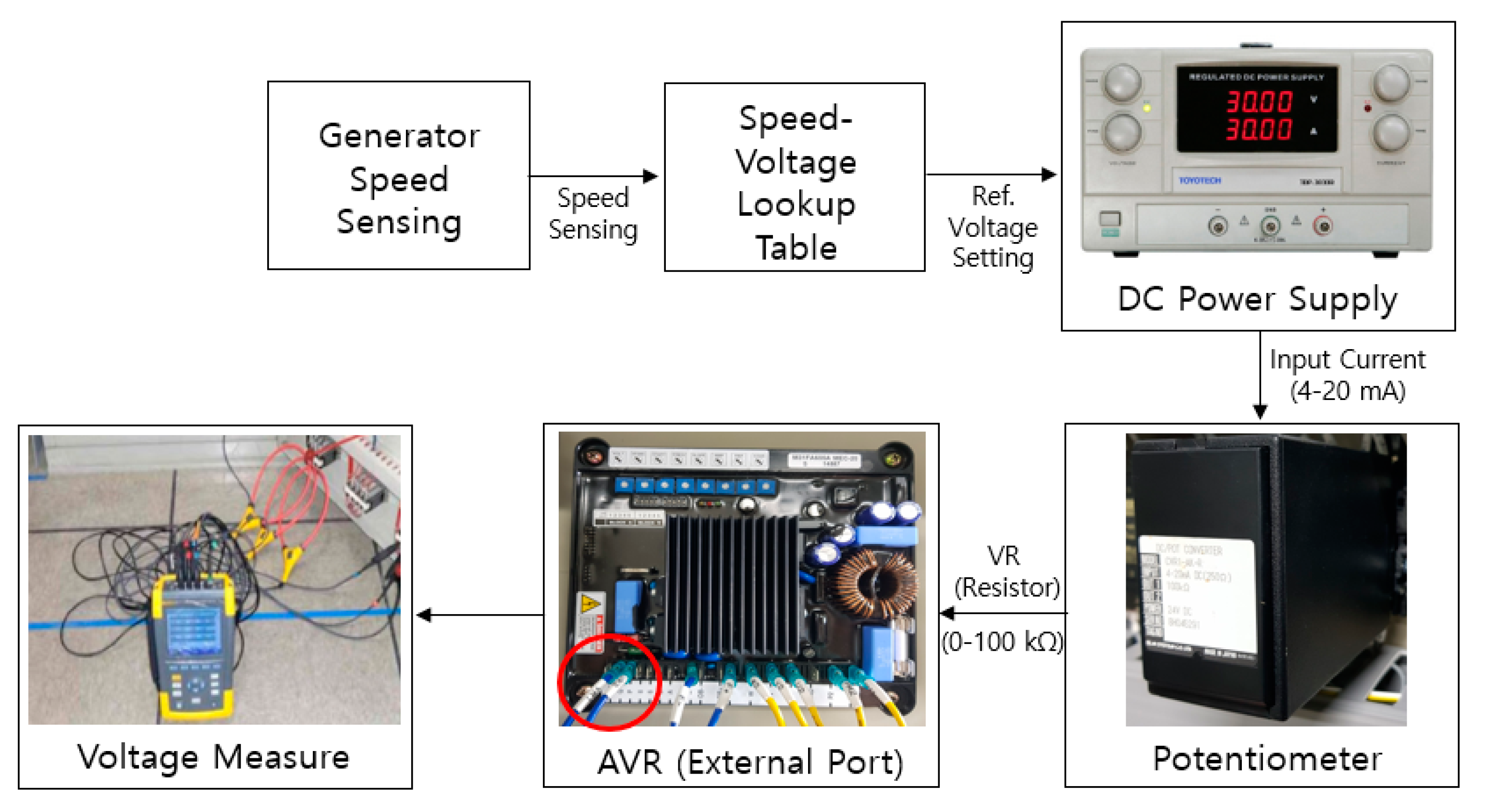
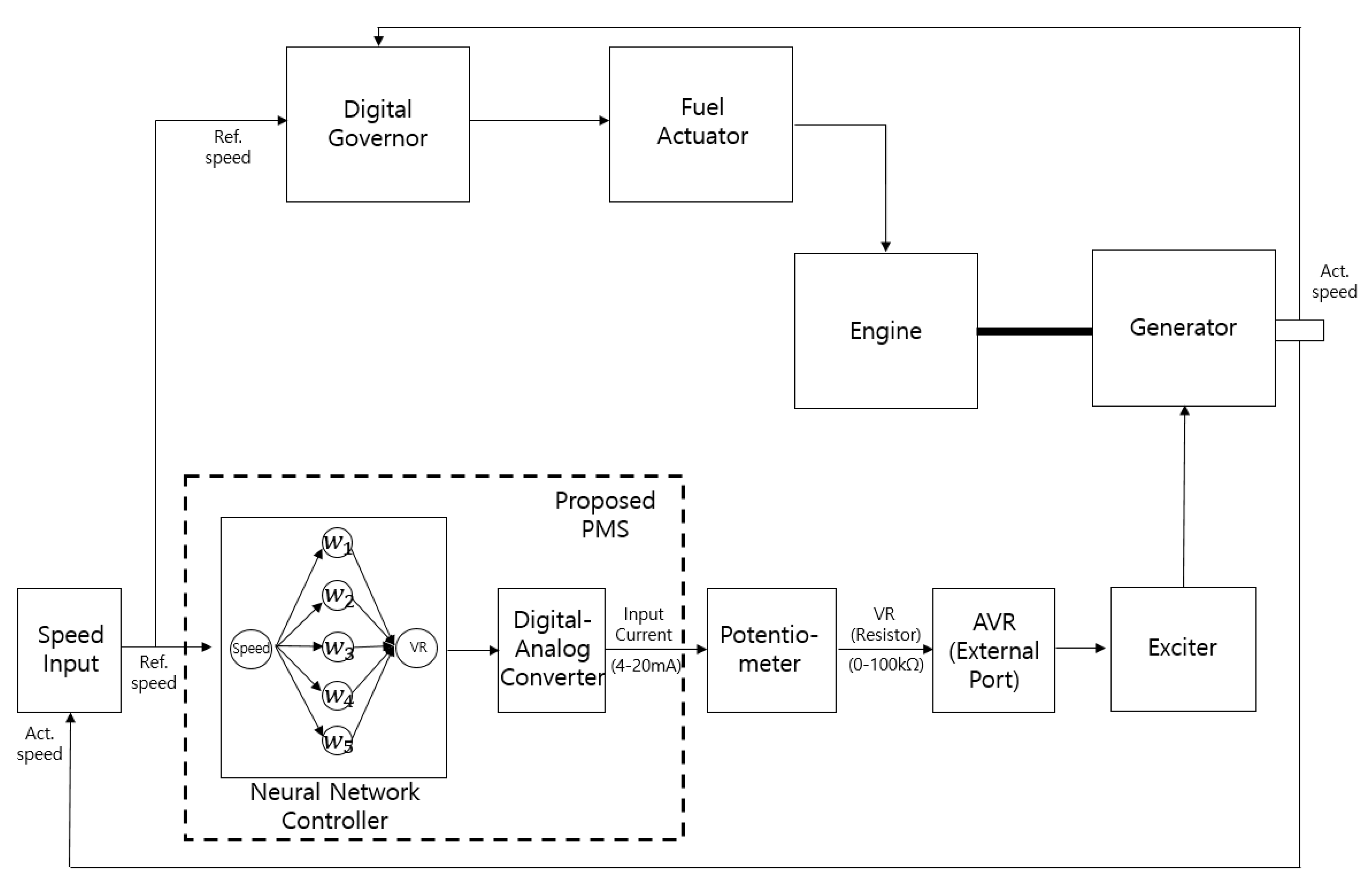
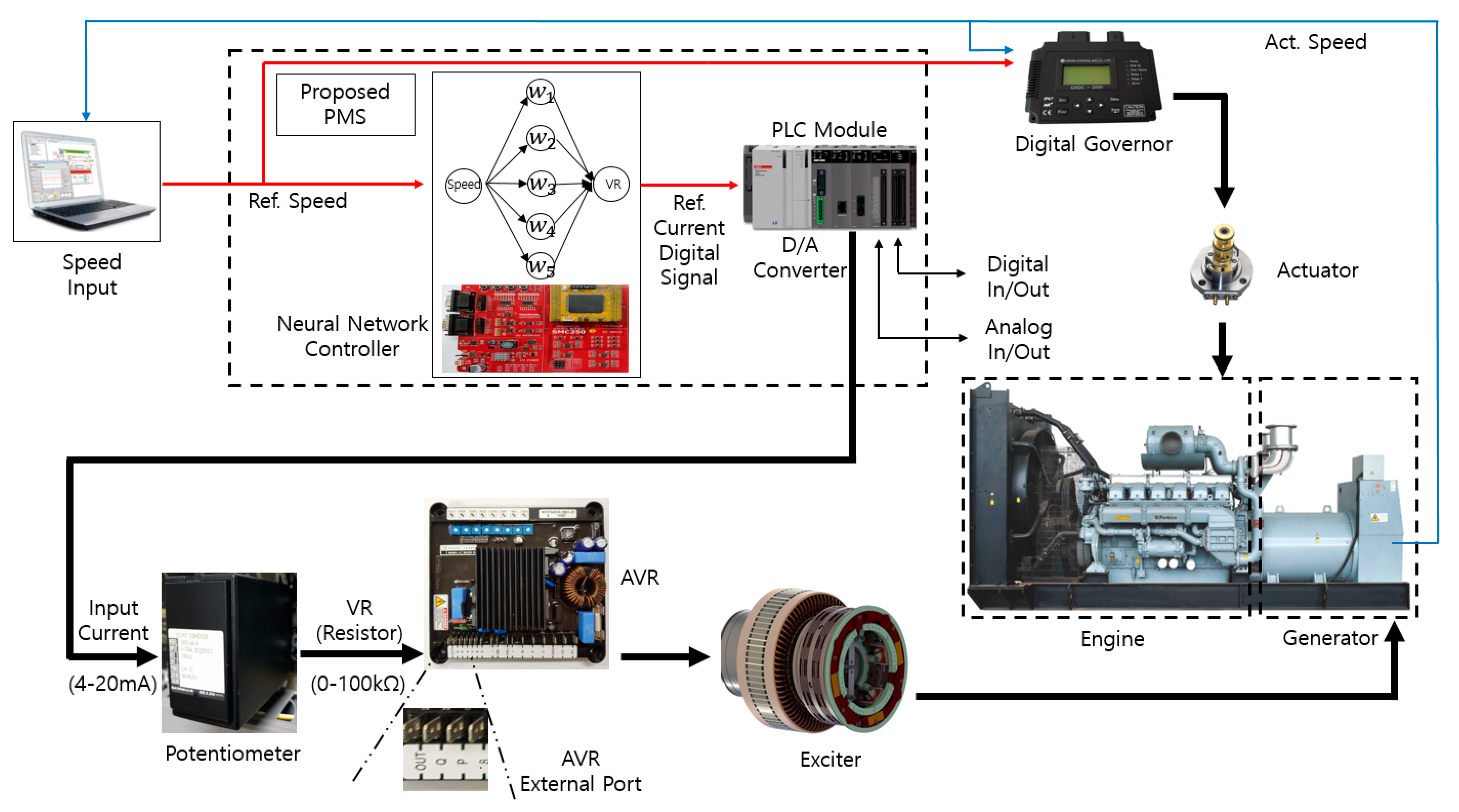
2.2.3. Step 3: Configuration of Experimental Apparatus
Variable Speed Synchronous Generator Engine
Power Management System
- -
- Control system
- -
- PLC
- -
- Communication device
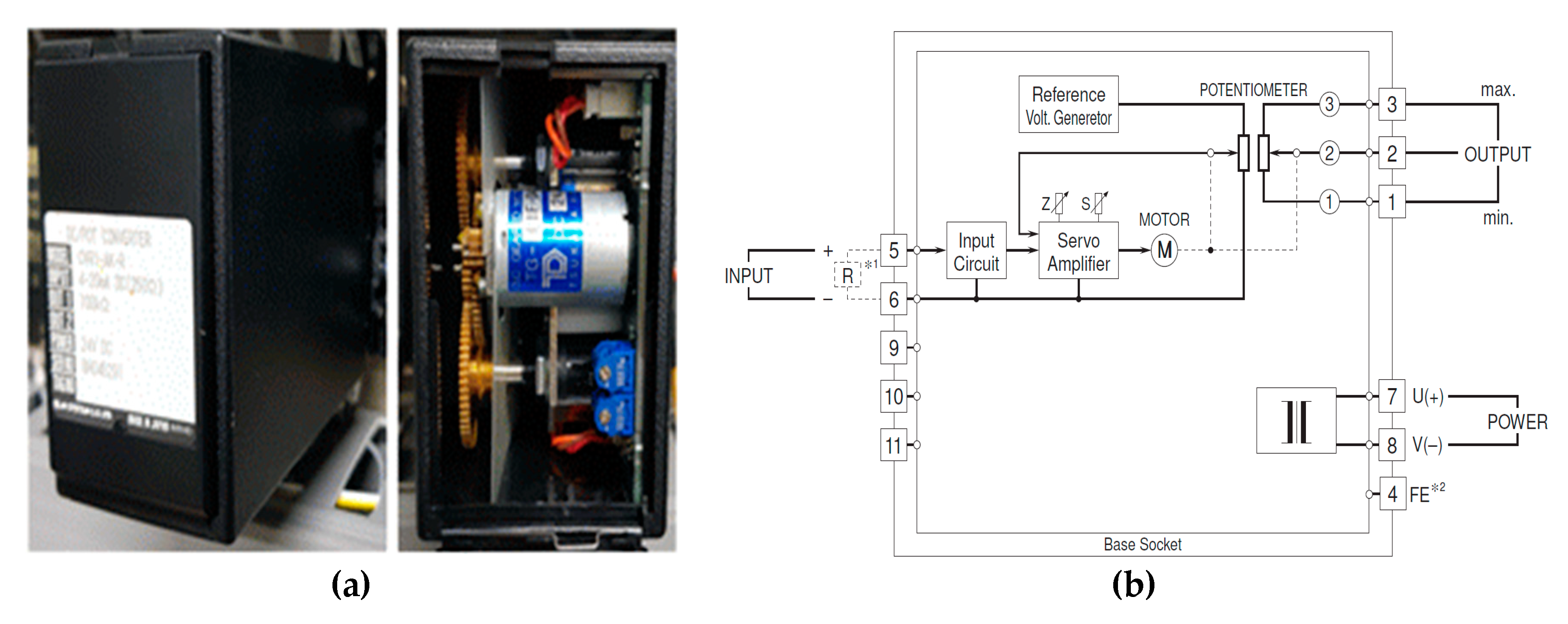
Potentiometer
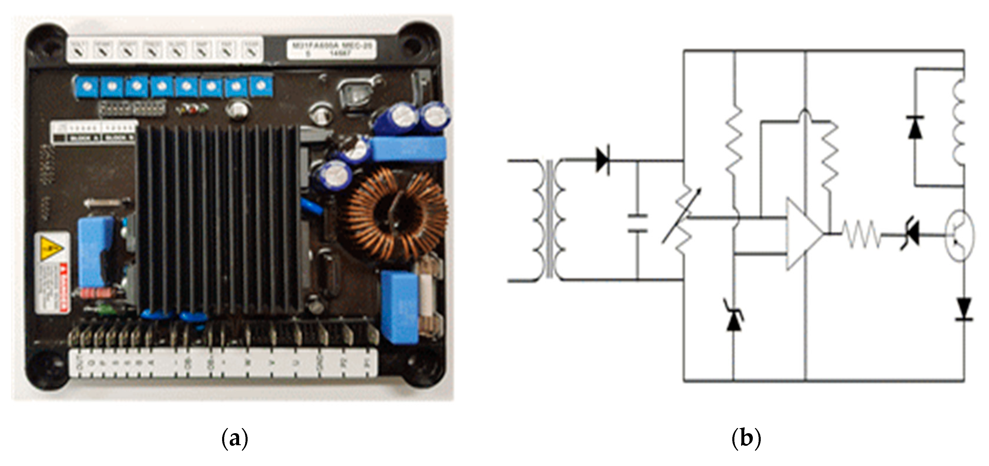
Reference Voltage Control Unit of the Automatic Voltage Regulator
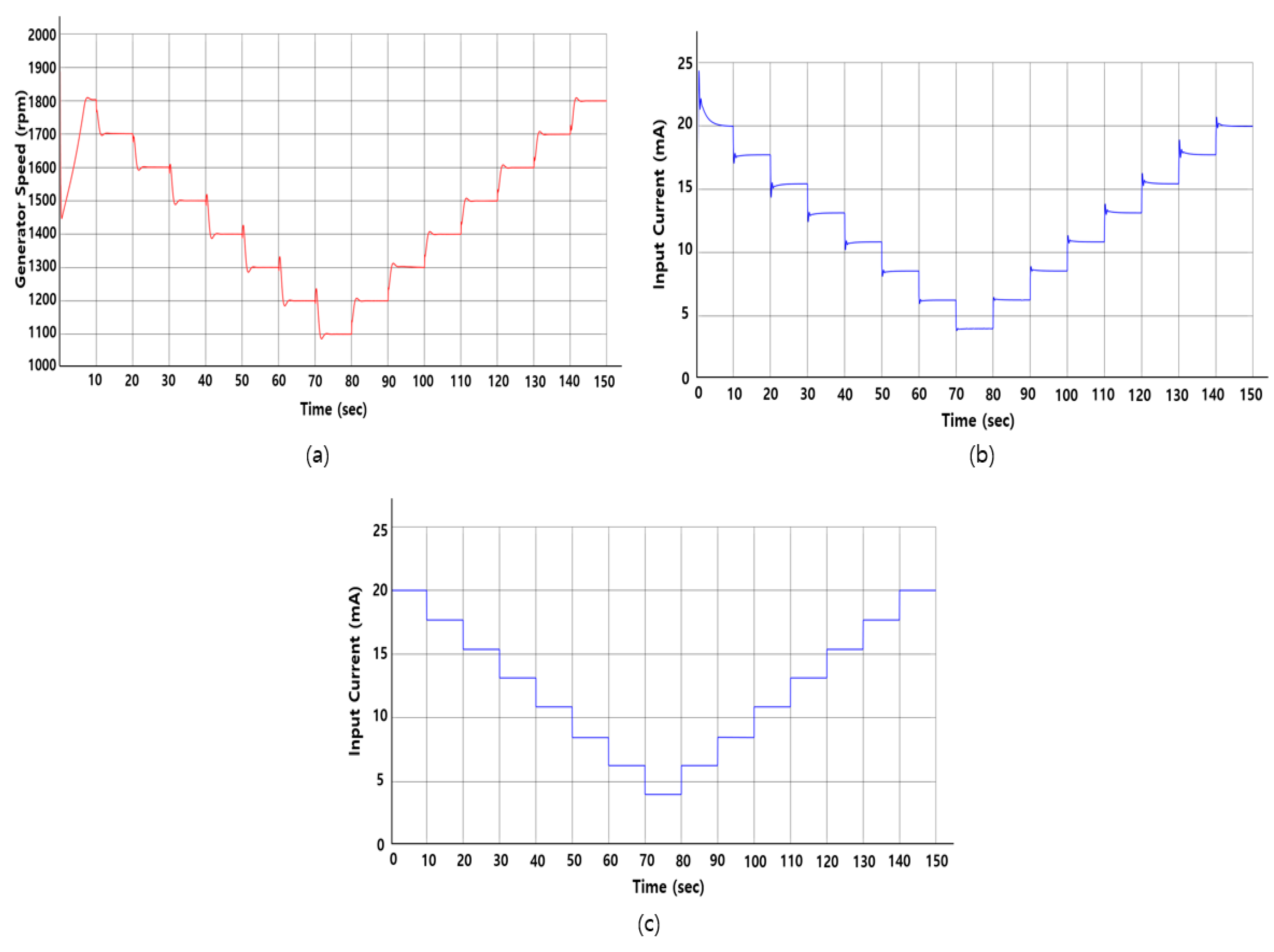
2.2.4. Step 4: Analysis of Output Results
3. Experimental Results
4. Discussion
5. Conclusions
Author Contributions
Funding
Acknowledgments
Conflicts of Interest
References
- National Air Pollutants Emission Information Center. National Air Pollutants Emission Service. Available online: https://airemiss.nier.go.kr/mbshome/mbs/airemiss/index.do (accessed on 5 June 2020).
- Lee, T.; Nam, H. A study on green shipping in major countries: In the view of shipyards, shipping companies, ports, and policies. Asian J. Shipp. Logist. 2017, 33, 253–262. [Google Scholar] [CrossRef]
- IMO. Fourth IMO Greenhouse Gas Study 2020. Available online: http://asq.kr/n8ptzWc9z1ce! (accessed on 23 September 2020).
- KMI. Trend Analysis Report. Available online: http://bitly.kr/b73lIU2jbPY (accessed on 24 May 2020).
- KMI. A Study on Assessment and Certification System for Reduction Technology of Emission from Ships; KMI: Busan, Korea, 2019. [Google Scholar]
- MOTIE. Laying the Legal Basis for Expanding the Development and Distribution of Eco-Friendly Ships. Available online: http://bitly.kr/Up78GmWPmyaU (accessed on 3 July 2020).
- Clarksons Research. Reearch’s World Fleet Register. Available online: http://asq.kr/VzUZAmVkV1HB (accessed on 15 June 2020).
- Jeon, H.; Kim, J.; Yoon, K.-K. Large-scale electric propulsion systems in ships using an active front-end rectifier. J. Mar. Sci. Eng. 2019, 7, 168. [Google Scholar] [CrossRef] [Green Version]
- Market Research Report. Electric Ships Market by Power Source, Autonomy, Ship Type and Region-Global Forecast to 2030. Available online: http://asq.kr/WM1G9LIRDimX (accessed on 11 June 2020).
- Machowski, J.; Robak, S.; Bialek, J.W.; Bumby, J.R.; Abi-Samra, N. Decentralized stability-enhancing control of synchronous generator. IEEE Trans. Power Syst. 2000, 15, 1336–1344. [Google Scholar] [CrossRef]
- Luo, L.; Gao, L.; Fu, H. The control and modeling of diesel generator set in electric propulsion ship. Int. J. Inf. Technol. Comput. Sci. 2011, 3, 31–37. [Google Scholar] [CrossRef]
- Anbarasi, S.; Muralidharan, S. Enhancing the transient performances and stability of AVR system with BFOA tuned PID controller. J. Control Eng. Appl. Inform. 2016, 18, 20–29. [Google Scholar]
- Bhatt, V.K.; Bhongade, S. Design of PID controller in automatic voltage regulator (AVR) system using PSO technique. Int. J. Eng. Res. Appl. 2013, 3, 1480–1485. [Google Scholar]
- Gaing, Z.-L. A particle swarm optimization approach for optimum design of PID controller in AVR system. IEEE Trans. Energy Convers. 2004, 19, 384–391. [Google Scholar] [CrossRef] [Green Version]
- Mosaad, A.M.; Attia, M.A.; Abdelaziz, A.Y. Whale optimization algorithm to tune PID and PIDA controllers on AVR system. Ain Shams Eng. J. 2019, 10, 755–767. [Google Scholar] [CrossRef]
- Zamani, M.; Karimi-Ghartemani, M.; Sadati, N.; Parniani, M. Design of a fractional order PID controller for an AVR using particle swarm optimization. Control Eng. Pract. 2009, 17, 1380–1387. [Google Scholar] [CrossRef]
- Sedaghati, A. A PI controller based on gain-scheduling for synchronous generator. Turk. J. Electr. Eng. Comput. Sci. 2006, 14, 241–251. [Google Scholar]
- Kim, K.; Rao, P.; Burnworth, J.A. Self-tuning of the PID controller for a digital excitation control system. IEEE Trans. Ind. Appl. 2010, 46, 1518–1524. [Google Scholar] [CrossRef]
- Çelik, E. Incorporation of stochastic fractal search algorithm into efficient design of PID controller for an automatic voltage regulator system. Neural Comput. Appl. 2018, 30, 1991–2002. [Google Scholar] [CrossRef]
- Al Gizi, A.J.; Mustafa, M.; Al Zaidi, K.M.; Al-Zaidi, M.K. Integrated PLC-fuzzy PID Simulink implemented AVR system. Int. J. Electr. Power Energy Syst. 2015, 69, 313–326. [Google Scholar] [CrossRef]
- Shao, L.; Gao, Y.; Shao, X.; Ou, Q.; Zhang, S.; Liu, Q.; Zhang, B.; Wu, J.; Ruan, Q.; Shen, L.; et al. CTLA-4 blockade reverses the Foxp3+ T-regulatory-cell suppression of anti-tuberculosis T-cell effector responses. In Proceedings of the Application of self-tuning fuzzy PID controller on the AVR system. In Proceedings of the 2012 IEEE International Conference on Mechatronics and Automation, Chengdu, China, 5–8 August 2012; Cold Spring Harbor Laboratory: New York, NY, USA, 2020; pp. 2510–2514. [Google Scholar]
- Mukherjee, V.; Ghoshal, S. Comparison of intelligent fuzzy based AGC coordinated PID controlled and PSS controlled AVR system. Int. J. Electr. Power Energy Syst. 2007, 29, 679–689. [Google Scholar] [CrossRef]
- Vasanthi, S.; Gopila, M.; Gnanambal, I. Fuzzy and PID excitation control system with AVR in power system stability analysis. Int. J. Eng. Adv. Technol. 2012, 2249–8958. [Google Scholar]
- Ansari, J.A.; Shah, M.A. Probabilistic feedforward neural network based power system stabilizer for excitation control system of synchronous generator. Bahria Univ. J. Inf. Commun. Technol. 2015, 8, 70–74. [Google Scholar]
- Bhutto, A.A.; Chachar, F.A.; Hussain, M.; Bhutto, D.K.; Bakhsh, S.E. Implementation of probabilistic neural network (PNN) based automatic voltage regulator (AVR) for excitation control system in Matlab. In Proceedings of the 2019 2nd International Conference on Computing, Mathematics and Engineering Technologies (iCoMET), Sukkur, Pakistan, 30–31 January 2019; Institute of Electrical and Electronics Engineers (IEEE): New York, NY, USA, 2019; pp. 1–5. [Google Scholar]
- Memon, A.P.; Memon, A.S.; Akhund, A.A.; Memon, R.H. Multilayer perceptrons neural network automatic voltage regulator with applicability and improvement in power system transient stability. Int. J. Emerg. Trends Electr. Electron. 2013, 9, 30–38. [Google Scholar]
- Senjyu, T.; Fujita, H. Recurrent neural network supplementary stabilization controller for automatic voltage regulator and governor. Electr. Power Components Syst. 2003, 31, 693–707. [Google Scholar] [CrossRef]
- Hansen, J.F.; Wendt, F.; Lindtjørn, J.O. In Fuel-efficient power plant featuring variable speed generation system for DP drilling units. In Proceedings of the Dynamic Positioning Conference, Houston, TX, USA, 11–12 October 2016; pp. 1–13. [Google Scholar]
- Miyazaki, M.R.; Sorensen, A.J.; Vartdal, B.J. Reduction of fuel consumption on hybrid marine power plants by strategic loading with energy storage devices. IEEE Power Energy Technol. Syst. J. 2016, 3, 207–217. [Google Scholar] [CrossRef]
- Yuan, L.C.W.; Tjahjowidodo, T.; Lee, G.S.G.; Chan, R.; Ådnanes, A.K. In Equivalent consumption minimization strategy for hybrid all-electric tugboats to optimize fuel savings. In Proceedings of the 2016 American Control Conference (ACC), Boston, MA, USA, 6–8 July 2016; pp. 6803–6808. [Google Scholar]
- De Jong, W.; Robinson, J. Generator failures caused by synchronising torques. Inst. Mar. Eng. Trans. 1986, 99, 8. [Google Scholar]
- Gross, L.C.; Anderson, L.S.; Young, R.C. Avoid Generator and System Damage Due to a Slow Synchronizing Breaker; Wisconsin Electric Power Company and Schweitzer Engineering Laboratories: Pullman, WA, USA, 1997. [Google Scholar]
- Oh, S.J.; Kim, H.S.; Kim, S.H. A Study on the Transient Phenomenon Analysis at the instant of Parallel Running for AC Generators. J. Korean Soc. Mar. Eng. 2001, 25, 1065–1075. [Google Scholar]
- Oh, S.-G.; Kim, J.-S.; Kim, S.-H.; Lee, S.-G.; Jo, S.-K. A Study on the transient phenomenon analysis of ship generator synchronization. J. Korean Soc. Mar. Eng. 2007, 31, 998–1004. [Google Scholar] [CrossRef]
- Kim, K.; Park, K.; Roh, G.; Chun, K. DC-grid system for ships: A study of benefits and technical considerations. J. Int. Marit. Saf. Environ. Aff. Shipp. 2018, 2, 1–12. [Google Scholar] [CrossRef] [Green Version]
- Hansen, J.F.; Wendt, F. History and state of the art in commercial electric ship propulsion, integrated power systems, and future trends. Proc. IEEE 2015, 103, 2229–2242. [Google Scholar] [CrossRef]
- Tufte, E.D. Impacts of Low Load Operation of Modern Four-Stroke Diesel Engines in Generator Configuration. Master’s Thesis, NTNU, Trondheim, Norway, 2014. [Google Scholar]
- Kozak, M. In New concept of ship’s power plant system with varying rotational speed gensets. In Proceedings of the 58th International Conference of Machine Design Departments, Prague, Czech Republic, 6–8 September 2017; pp. 170–175. [Google Scholar]
- Mozina, C.J. Lessons Learned From Generator Tripping Events. IEEE Ind. Appl. Mag. 2010, 16, 29–36. [Google Scholar] [CrossRef]
- Alves, E.F.; De Souza, M.A. Analysis of overexcitation relaying set up in synchronous generators for hydro power plants. In Proceedings of the 2008 IEEE/PES Transmission and Distribution Conference and Exposition, Bogota, Columbia, 13–15 August 2008; Institute of Electrical and Electronics Engineers (IEEE): New York, NY, USA, 2010; pp. 298–303. [Google Scholar]
- Sasic, M. Deterioration Processes in Large Generator Stator Cores. Available online: http://asq.kr/PaHRjslKazH (accessed on 2 July 2020).
- Hasani, A.; Haghjoo, F.; Da Silva, F.F.; Bak, C.L. Loss of field protection of synchronous generator in a realistic framework using RTDS. In Proceedings of the 2018 IEEE International Conference on Environment and Electrical Engineering and 2018 IEEE Industrial and Commercial Power Systems Europe (EEEIC/I&CPS Europe), Palrmo, Italy, 12–15 June 2018; pp. 1–5. [Google Scholar]
- Planas, E.; Andreu, J.; Gárate, J.I.; De Alegría, I.M.; Ibarra, E. AC and DC technology in microgrids: A review. Renew. Sustain. Energy Rev. 2015, 43, 726–749. [Google Scholar] [CrossRef]
- Prenc, R.; Cuculić, A.; Baumgartner, I. Advantages of using a DC power system on board ship. J. Marit. Transp. Sci. 2016, 52, 83–97. [Google Scholar] [CrossRef] [Green Version]
- Baran, M.; Mahajan, N. DC distribution for industrial systems: Opportunities and challenges. IEEE Trans. Ind. Appl. 2003, 39, 1596–1601. [Google Scholar] [CrossRef]
- Castellan, S.; Menis, R.; Tessarolo, A.; Sulligoi, G. In Power electronics for all-electric ships with MVDC power distribution system: An overview. In Proceedings of the 2014 Ninth International Conference on Ecological Vehicles and Renewable Energies (EVER), Monte Carlo, Monaco, 25–27 March 2014; pp. 1–7. [Google Scholar]
- Hammerstrom, D.J. In AC versus DC distribution systemsdid we get it right? In Proceedings of the 2007 IEEE Power Engineering Society General Meeting, Tampa, FL, USA, 24–28 June 2007; pp. 1–5. [Google Scholar]
- Hansen, J.F.; Lindtjørn, J.O.; Vanska, K. In Onboard DC Grid for enhanced DP operation in ships. In Proceedings of the Dynamic Positioning Conference, Houston, TX, USA, 11–12 October 2011; pp. 1–8. [Google Scholar]
- Syverud, T.H. Modeling and Control of a DC-Grid Hybrid Power System with Battery and Variable Speed Diesel Generators. Master’s Thesis, NTNU, Trondheim, Norway, 2016. [Google Scholar]
- Geertsma, R.; Negenborn, R.; Visser, K.; Hopman, J. Design and control of hybrid power and propulsion systems for smart ships: A review of developments. Appl. Energy 2017, 194, 30–54. [Google Scholar] [CrossRef]
- ABB. ABB: Tests Confirm up to 27% Fuel Savings on Ships from Onboard DC Grid. Available online: http://asq.kr/uFww4mREiCMK (accessed on 8 May 2020).
- Mozina, C.J.; Reichard, M.; Bukhala, Z.; Conrad, S.; Crawley, T.; Gardell, J.; Hamilton, R.; Hasenwinkle, I.; Herbst, D.; Henriksen, L. In Coordination of generator protection with generator excitation control and generator capability. In Proceedings of the Conference Record of 2008 54th Annual Pulp and Paper Industry Technical Conference, Seattle, WA, USA, 22–27 June 2008; pp. 62–76. [Google Scholar]
- Maughan, C.V. Generator Inspections, Failures. Combined Cycle J. 2011. [Google Scholar]
- Demuth, H.B.; Beale, M.H.; De Jess, O.; Hagan, M.T. Neural Network Design, 2nd ed.; Campus Pub. Service, University of Colorado Bookstore: Boulder, CO, USA, 2002. [Google Scholar]
- Haykin, S.S. Neural Networks and Learning Machines, 1st ed.; Prentice Hall: New York, NY, USA, 2009. [Google Scholar]
- Hameed, A.A.; Karlik, B.; Salman, M.S. Back-propagation algorithm with variable adaptive momentum. Knowl.-Based Syst. 2016, 114, 79–87. [Google Scholar] [CrossRef]
- Li, J.; Cheng, J.-H.; Shi, J.-Y.; Huang, F. Brief Introduction of Back Propagation (BP) Neural Network Algorithm and Its Improvement. Adv. Intell. Soft Comp. 2012, 2, 553–558. [Google Scholar] [CrossRef]


| Type | Reference: Ship Name (Type, Delivery Year) |
|---|---|
| Generator main power | MS Viking Legend (Car ferry, 2009) |
| MS Viking Prestige (Car ferry, 2011) | |
| MV Jaguar (General cargo ship, 2012) | |
| Absis Dover (PSV, 2012) | |
| Dina Star (PSV, 2013) | |
| Edda Ferd (PSV, 2013) | |
| BB Green (Ferry, 2015) | |
| Damen Eco Liner (Tanker, 2015) | |
| Edda Freya (OSV, 2016) | |
| Harvey Stone (PSV, 2016) | |
| Vision of the Fjords (Car ferry, 2016) | |
| IJ Ferry 60, 61 (Passenger ferry, 2016–17) | |
| NKT Victoria (Cable laying vessel, 2017) | |
| Van Oords Nexus (Cable laying vessel, 2017) | |
| Battery main power | FCS Alsterwasser (Ferry, 2012) |
| Ampere (Car ferry, 2014) | |
| Tycho Brahe and Aurora of HH ferries (Car ferry, 2017) | |
| Elektra (Ferry, 2017) | |
| Guangzhou Shipyard International (Cargo ship, 2017) | |
| E-ferry (Car ferry, 2018) |
| Item | Model | Description |
|---|---|---|
| Diesel Engine | P158LE-III | 400 kW |
| Alternator | MJB 355SB4 | 440 VAC, 60 Hz |
| Digital Governor | GNDC-1000 | Engine Control |
| Microprocessor | TMS320F28377D | Neural Network Controller |
| PLC Module | XGB XBC-DN32 | Analog, Digital data in/out |
| Communication Device | ADAM 4520 | RRS485 to RS232 Converter |
| Potentiometer | CVR1-AK-R | AVR External resistance control |
| AVR | M31FA600A MEC-20 | Voltage control |
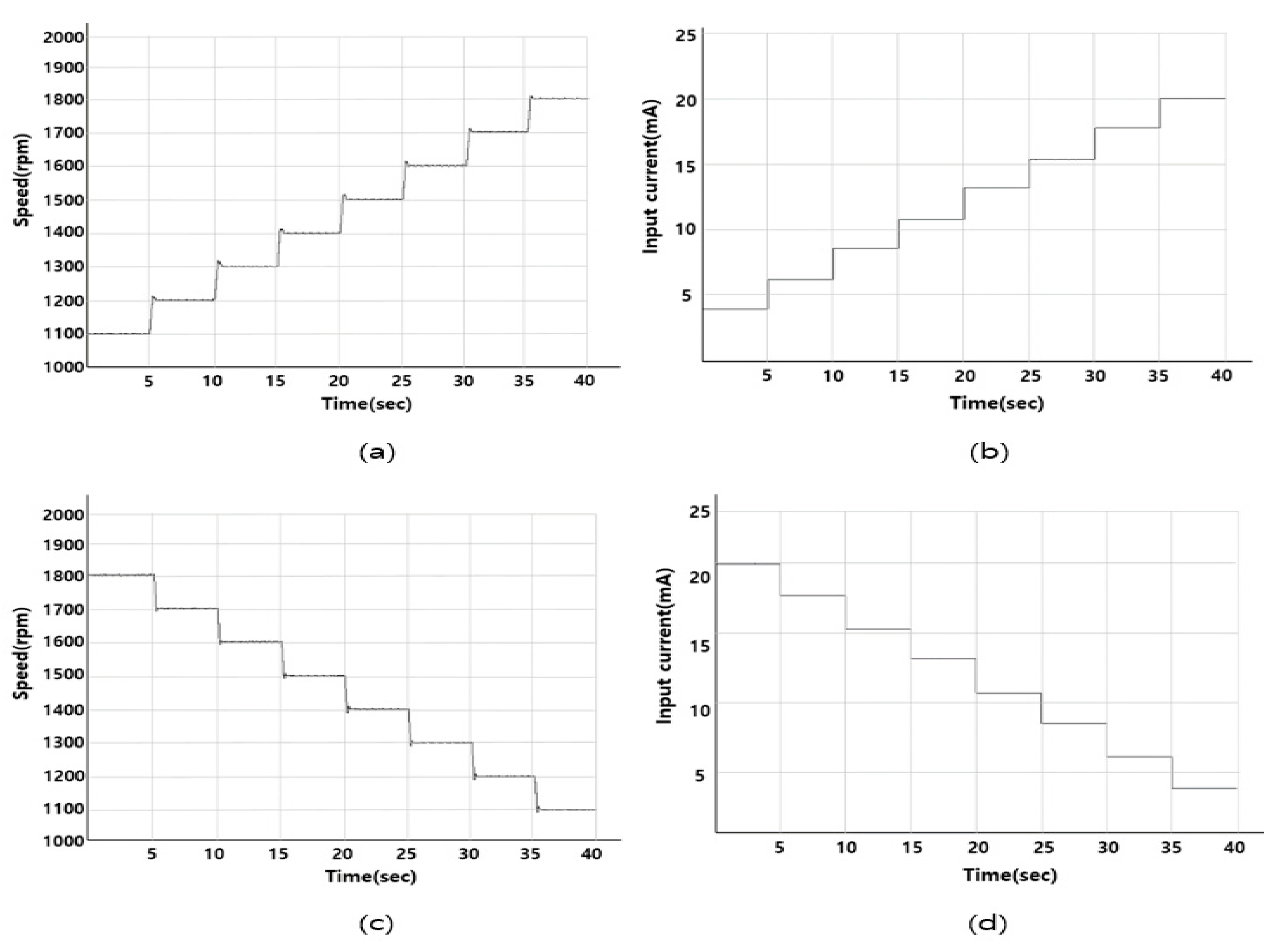
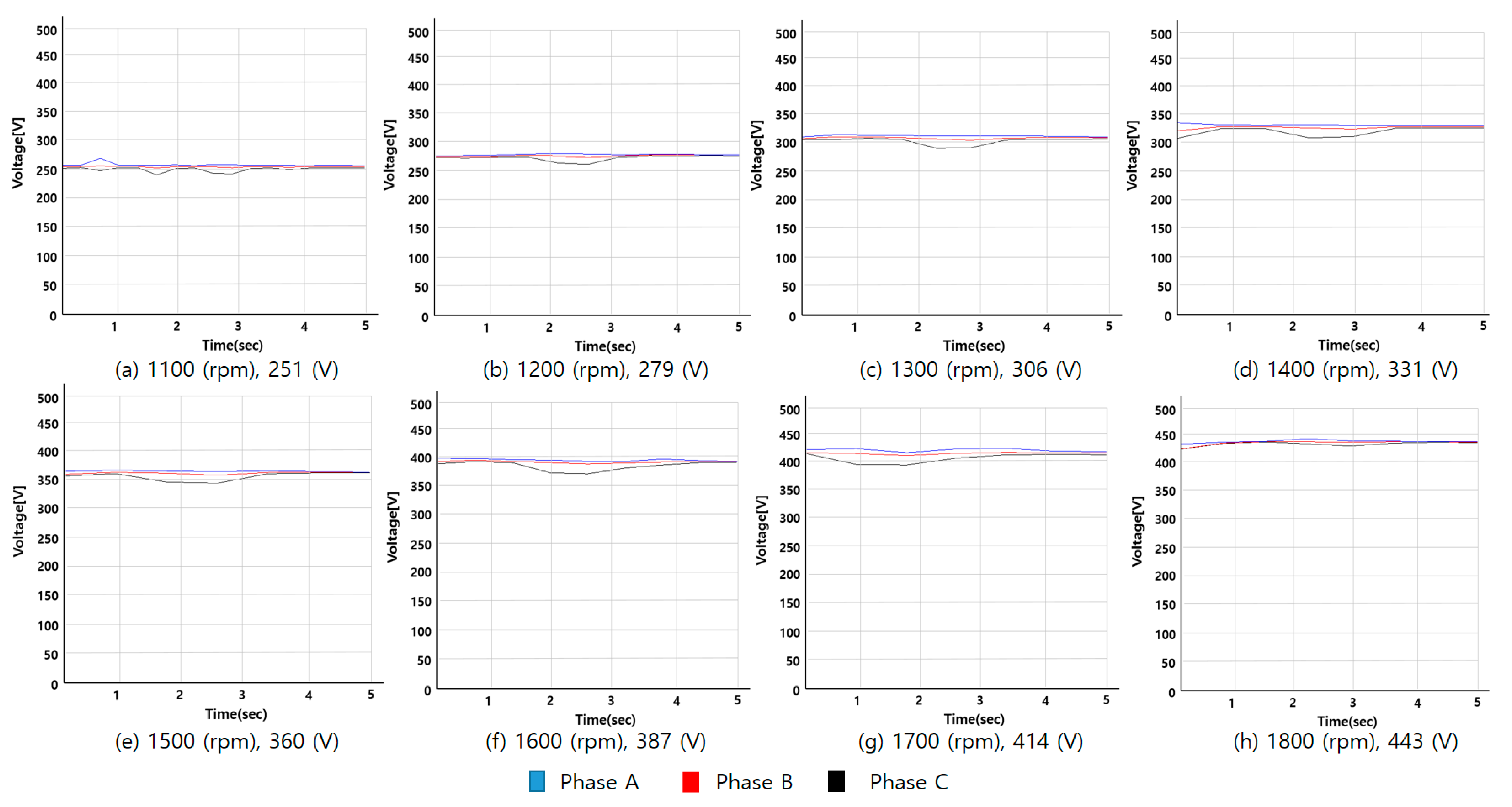
| Generator Engine Speed (rpm) | Generator Voltage (VAC) | Generator Frequency (Hz) | Potentiometer Input Current (mA) | AVR External Resistance Value (kΩ) |
|---|---|---|---|---|
| 1100 | 251 | 36.7 | 4.0011 | 4.15 |
| 1200 | 279 | 40 | 6.2388 | 18.22 |
| 1300 | 306 | 43.3 | 8.6048 | 33.67 |
| 1400 | 331 | 46.7 | 10.7804 | 47.1 |
| 1500 | 360 | 50 | 13.2004 | 62.9 |
| 1600 | 387 | 53.3 | 15.3152 | 75.9 |
| 1700 | 414 | 56.7 | 17.7208 | 91.3 |
| 1800 | 443 | 60 | 19.9908 | 98.5 |
| Load(kW) | Scale down Load(kW)/Pattern | Energy Source |
|---|---|---|
| 1423.7 | 125(Normal seagoing without reefer) | Only DG |
| 4153.7 | 357(Normal seagoing with reefer) | Only DG |
| 2148.1 | 187(Port in/out without thruster) | Only DG |
| 3860.4 | 332(Port in/out with thruster) | Only DG |
| 3714.6 | 320(Loading/Unloading) | Only DG |
Publisher’s Note: MDPI stays neutral with regard to jurisdictional claims in published maps and institutional affiliations. |
© 2020 by the authors. Licensee MDPI, Basel, Switzerland. This article is an open access article distributed under the terms and conditions of the Creative Commons Attribution (CC BY) license (http://creativecommons.org/licenses/by/4.0/).
Share and Cite
Jeon, H.; Kim, J. Application of Reference Voltage Control Method of the Generator Using a Neural Network in Variable Speed Synchronous Generation System of DC Distribution for Ships. J. Mar. Sci. Eng. 2020, 8, 802. https://doi.org/10.3390/jmse8100802
Jeon H, Kim J. Application of Reference Voltage Control Method of the Generator Using a Neural Network in Variable Speed Synchronous Generation System of DC Distribution for Ships. Journal of Marine Science and Engineering. 2020; 8(10):802. https://doi.org/10.3390/jmse8100802
Chicago/Turabian StyleJeon, Hyeonmin, and Jongsu Kim. 2020. "Application of Reference Voltage Control Method of the Generator Using a Neural Network in Variable Speed Synchronous Generation System of DC Distribution for Ships" Journal of Marine Science and Engineering 8, no. 10: 802. https://doi.org/10.3390/jmse8100802