Article

Methodology for Indoor Positioning and Landing of an Unmanned Aerial Vehicle in a Smart Manufacturing Plant for Light Part Delivery

by
Pedro Orgeira-Crespo
1,*,
Carlos Ulloa
1,
Guillermo Rey-Gonzalez
1 and
José Antonio Pérez García
2
1
Aerospace Area, Department of Mechanical Engineering, Heat Engines and Machines, and Fluids, Aerospace Engineering School, University of Vigo, Campus Orense, 32004 Orense, Spain
2
Design Engineering Department, Industrial Engineering School, University of Vigo, 36310 Vigo, Spain
*
Author to whom correspondence should be addressed.
Electronics 2020, 9(10), 1680; https://doi.org/10.3390/electronics9101680
Submission received: 18 September 2020 / Revised: 3 October 2020 / Accepted: 6 October 2020 / Published: 14 October 2020
(This article belongs to the Special Issue Autonomous Navigation Systems for Unmanned Aerial Vehicles)

Abstract

:
Unmanned aerial vehicles (UAV) are spreading their usage in many areas, including last-mile distribution. In this research, a UAV is used for performing light parts delivery to workstation operators within a manufacturing plant, where GPS is no valid solution for indoor positioning. A generic localization solution is designed to provide navigation using RFID received signal strength measures and sonar values. A system on chip computer is onboarded with two missions: first, compute positioning and provide communication with backend software; second, provide an artificial vision system that cooperates with UAV’s navigation to perform landing procedures. An Industrial Internet of Things solution is defined for workstations to allow wireless mesh communication between the logistics vehicle and the backend software. Design is corroborated through experiments that validate planned solutions.

1. Introduction and State of the Art

Unmanned aerial vehicles (UAVs) have irrupted from military and domestic entertainment uses, to distribution centers, count inventory warehouses, and supply chain logistics [1,2]. UAVs have high potential for bundle delivery in civil applications [3], having in the key speed capability, showed in several pilot tests (Amazon, Google), although yet adoption intention is still vague, because of many factors [4,5]. In logistics area, the feasibility of these flying artifacts has also been stated [6]. To achieve a certain expected delivery time from depots to customers, the infrastructure level is usually determined by simulation [7], and task-assignment and routes have to be calculated [8]. These routes must accommodate the physical constraints (locations of goods, delivery points), as in the vehicle routing problem [9]. UAVs have shown capabilities for delivering six kg payload to sixteen-kilometer distances [5], and demand as well as benefits in metropolitan areas have been estimated [10]. In urban and rural areas, UAVs have shown even lower environmental impact than traditional delivery systems [11]. Their capabilities also include coordination with trucks for last-mile distribution [12,13,14,15,16,17], profitable under many scenarios [18], specially under modular design [19]. The context of urgent goods is where important research focused [20], especially for urgent medicine transportation [21], or when roads have challenges for urgent medical supplies [22,23]. Other uses, like a life-ring delivery system, are also present [24]. Of special interest in industry are the few studies related to the evaluation, design, simulation and modelling of a drone fleet for transporting materials in a manufacturing plant [25,26,27,28]. To the best of our investigations, this is an area where research has not yet focused deeply, whilst it represents a promising alternative to traditional systems. Indoor delivery performed using UAV does not need important dedicated facilities and maintenance costs that conveyor belts and similar solutions require.
With regards UAV’s autonomous landing, computer vision has been covered in the literature through two main approaches: (a) the detection of natural environment (using line features detection of natural scenes [29] or natural landmarks [30]); (b) the use of artificial markers, where an element with a specific imagen pattern is placed in the landing region to be discovered and provide positioning and orientation (traditional “H-shape” [31], square-shaped [32], specially ARTag [33], ApriTag [34], and ArUco [35,36,37]). Indoors, especially in manufacturing plants, requires artificial markers to be deployed to allow pattern recognition and support landing. In our research, a conventional camera is selected to create a simple and affordable solution, and the recognition algorithm is simplified to reduce computing needs, and permit onboarding the system. For worker’s safety, and a proper use of the plant’s volume, a relatively high distance between flying height and the landing spot will be considered; this represents a challenge as the computer vision system has to cope with long-distance recognition of the landing pad, and short-range accuracy to have a small landing table. ArUco markers, a synthetic square marker made of a wide black border and an inner binary matrix that determines its unique identifier within a dictionary, has been successfully used for object tracking [38] and landing purposes [39].
Other research has focused on providing computer vision autonomous landing using system-on-chip devices like the Raspberry pi, based on its lightweight and computing capabilities. In [40], the focus is on simplifying the image processing algorithm so that the Raspberry-Pi 3 could handle the computer vision task and flight commanding; nevertheless, the use of floor features cannot provide the combination of long and short range recognition needed. Other studies like [41] or [42] solve the autonomous landing based on computer vision with Raspberry-Pi computers as well, but again do not focus on solving the challenge of identifying the landing pad keeping an accuracy on the small landing spot.
Indoor positioning has been intensively studied [43,44,45,46,47,48,49], since GPS is no valid solution inside a manufacturing plan. Main industry technologies involved in localization have been identified and classified as well according to their nominal operative range [50]; the set of technological solutions widely used in the industry includes NFC (Near Field Communication), RFID (Radio Frequency Identification), Bluetooth, Zigbee, ZWave, Wi-Fi, UWB, and others [2,16,51,52,53,54,55,56,57,58,59,60,61]. For items/parts, RFID has been extensively used for indoor object tracking [62,63,64], but when it comes to performing localization, RSS is commonly a difficult way to obtain precise positioning [65].
Finally, the aerial vehicle needs, as well a communication method, to receive navigation commands, report its location, and send telemetry information to the back end; reporting location is key for two aspects: (a) as means for finding it in case it does not reach its destination; (b) to provide the capability of more than one UAV delivering parts in the same plant, so that common aeronautic traffic control mechanisms can be implemented.
Consequently, three main goals have been defined for this research:
  • Provide an affordable indoor localization method for an unmanned aerial vehicle that delivers light parts inside a manufacturing plant.
  • Provide an autonomous landing system based on computer vision and affordable equipment that can be onboarded, generalizable for any manufacturing plant.
  • Provide an affordable wireless solution within a standard manufacturing plant for UAV messages (location, basic telemetry, and receiving simple commands) to be interchanged with the backend software that manages the delivery flights for these internal operations.
The work presented in this paper builds the indoor localization solution as a combination of: first, RSS (received signal strength) values from RFID passive tags accommodated in UAV’s flying corridors (coarse information on the zone where the UAV is located); second, sonar, providing accurate distance to perimetral walls for fine trajectory control; third, a specific design of flying corridor where the passive tags are located. The idea is to have an RFID reader onboard on the flying vehicle, and to locate several passive tags on well-known corridor’s location so that the UAV is detecting their presence as it navigates towards its destination. RFID for location has been already treated in the literature, but mostly focused in improving localization accuracy [66], or obtaining that accuracy by combining it with other methods [67]. In this research, to keep weight and computing requirements as low as possible, RFID RSS readings provide a coarse localization, and have been helped by sonar readings that gave fine trajectory following. A navigation algorithm is proposed to generalize the solution for any manufacturing plant, given its blueprints. A lightweight computer vision algorithm is defined to allow identification of the landing table and aid landing. Since flying height must be enough as not to obstruct work in the manufacturing plant, a combination of circle mark (for long-range) and a set of “ArUco” markers (for short-range) will control UAV’s vertical descent. A Raspberry Pi system on chip is onboarded to obtain RSS from the reader, distance readings from the sonar, compute the landing algorithm and handle communication with backend software. To address the need for a means to report location, telemetry, and receive commands from the backend software, a Zigbee mesh is proposed, using operator’s workstations. Again, a Raspberry Pi will be deployed to workstations so that Zigbee modules can forward UAV’s messages to the PAN (personal area network).
To summarize, the novelty of this work, in the scope of a UAV that delivers light parts to workstation operators within a manufacturing plant, lies on:
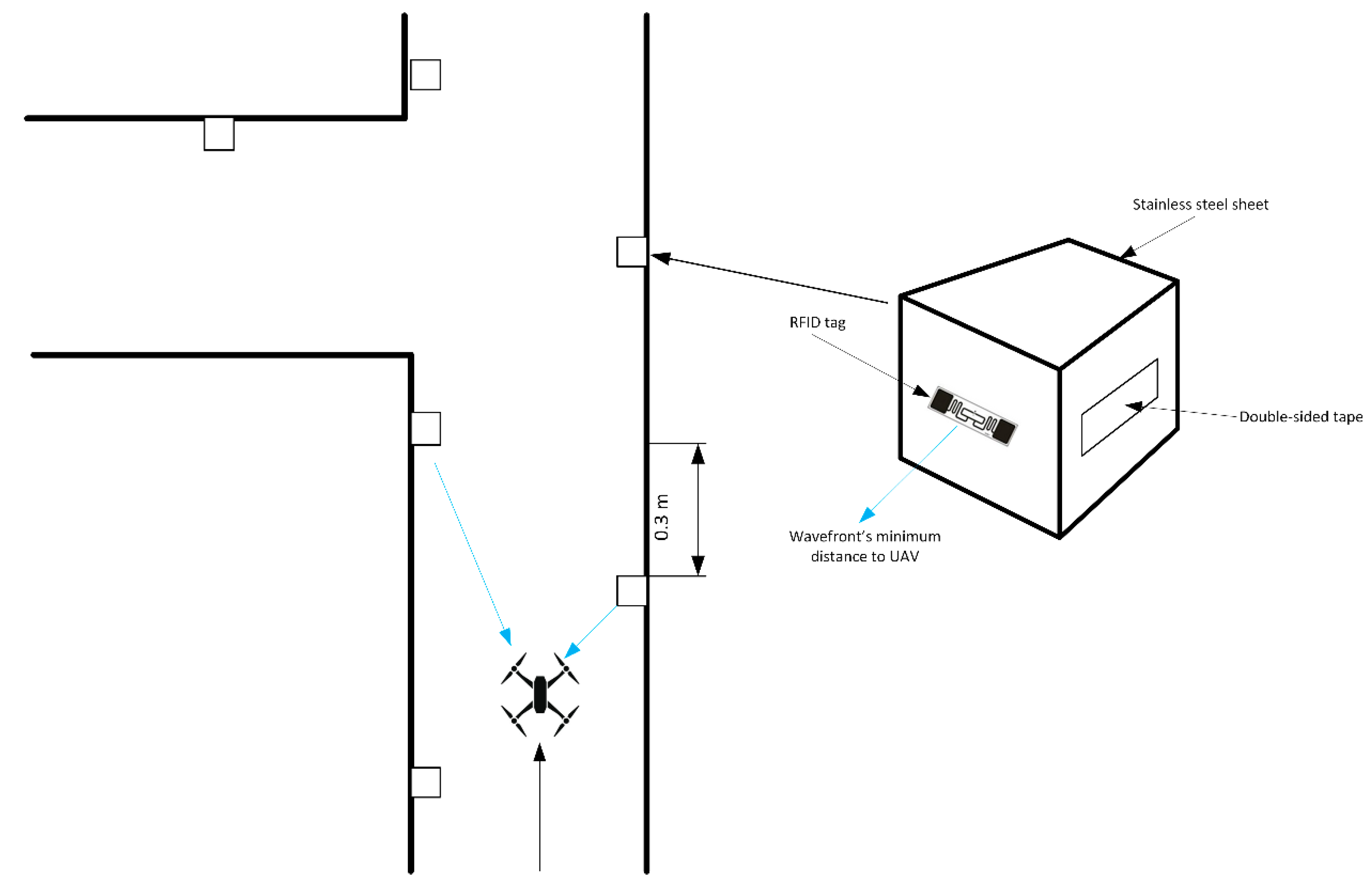
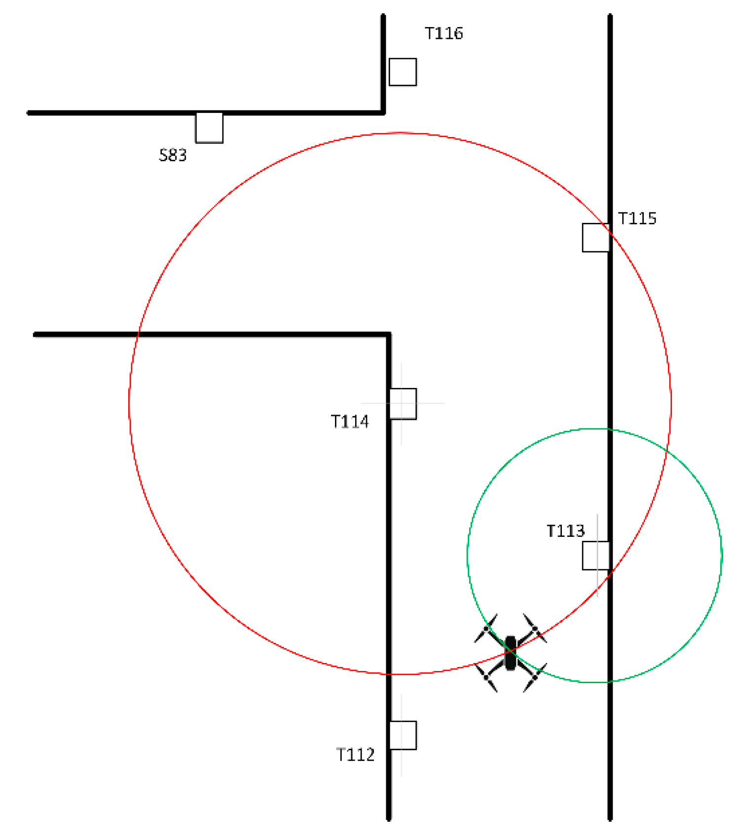
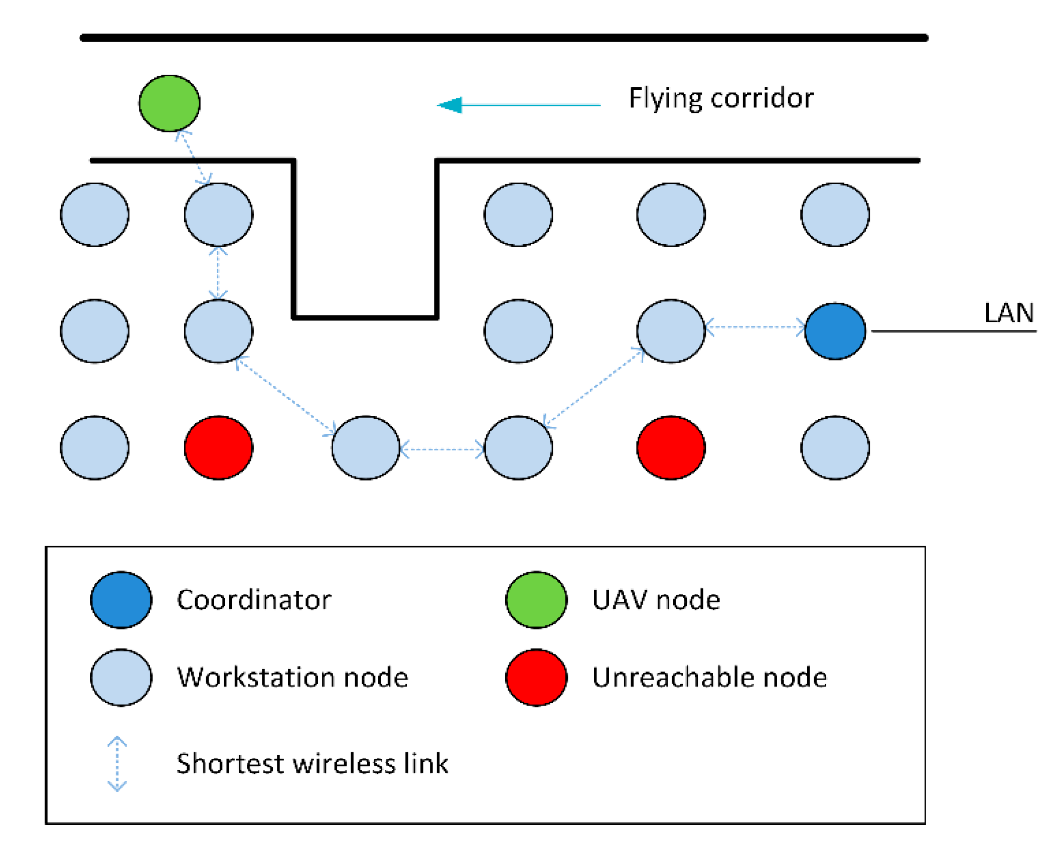
  • The positioning system: the utilization of RFID in conjunction with sonar readings from a different point of view (using the RSS values to obtain a coarse location, and the sonar to provide fine trajectory tracking, aided by a specific corridor design).
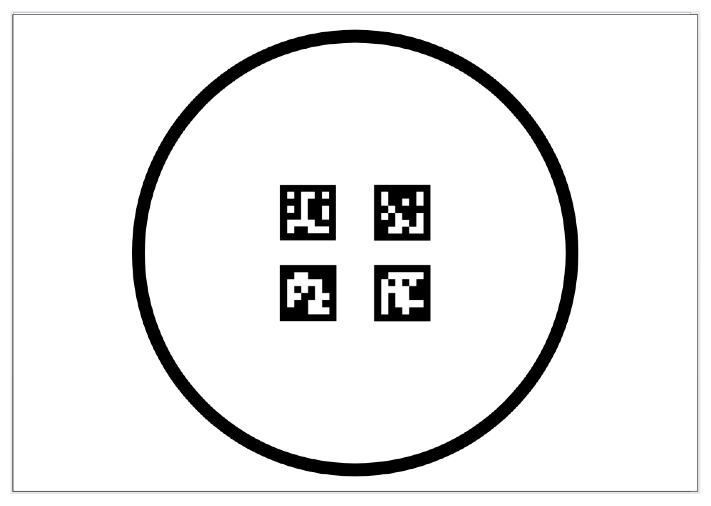
  • The landing system: the use of an onboarded camera that locates the right point to begin descent within the flying corridor, and that controls how the UAV descends (the combination of the circle shape for long-range and a special arrangement of four ArUco markers that provide accurate short-range control).
In conclusion, the novelty of this work lies in the use in conjunction RFID RSS values with sonar readings through a navigation algorithm, onboarding a system on chip and camera to perform positioning and landing, and the use of a mesh network for wireless communication within a manufacturing plant, in the scope of a UAV that delivers light parts to workstations operators.
This paper is organized as follows: Section 2 depicts the environment where the research is developed; localization algorithm is described, and flying corridors are defined; flight control and manufacturing plant abstraction are also illustrated; computer vision is also described, including the description of the vertical descent; communication with a back-end software is also designed, and the materials used are also indicated. Section 3 shows laboratory assessments performed to test design; positioning system is evaluated to review localization capabilities; computer vision landing system is also evaluated through a series of tests. Section 4 summarizes conclusions, and possible future lines of work.

2. Materials and Methods
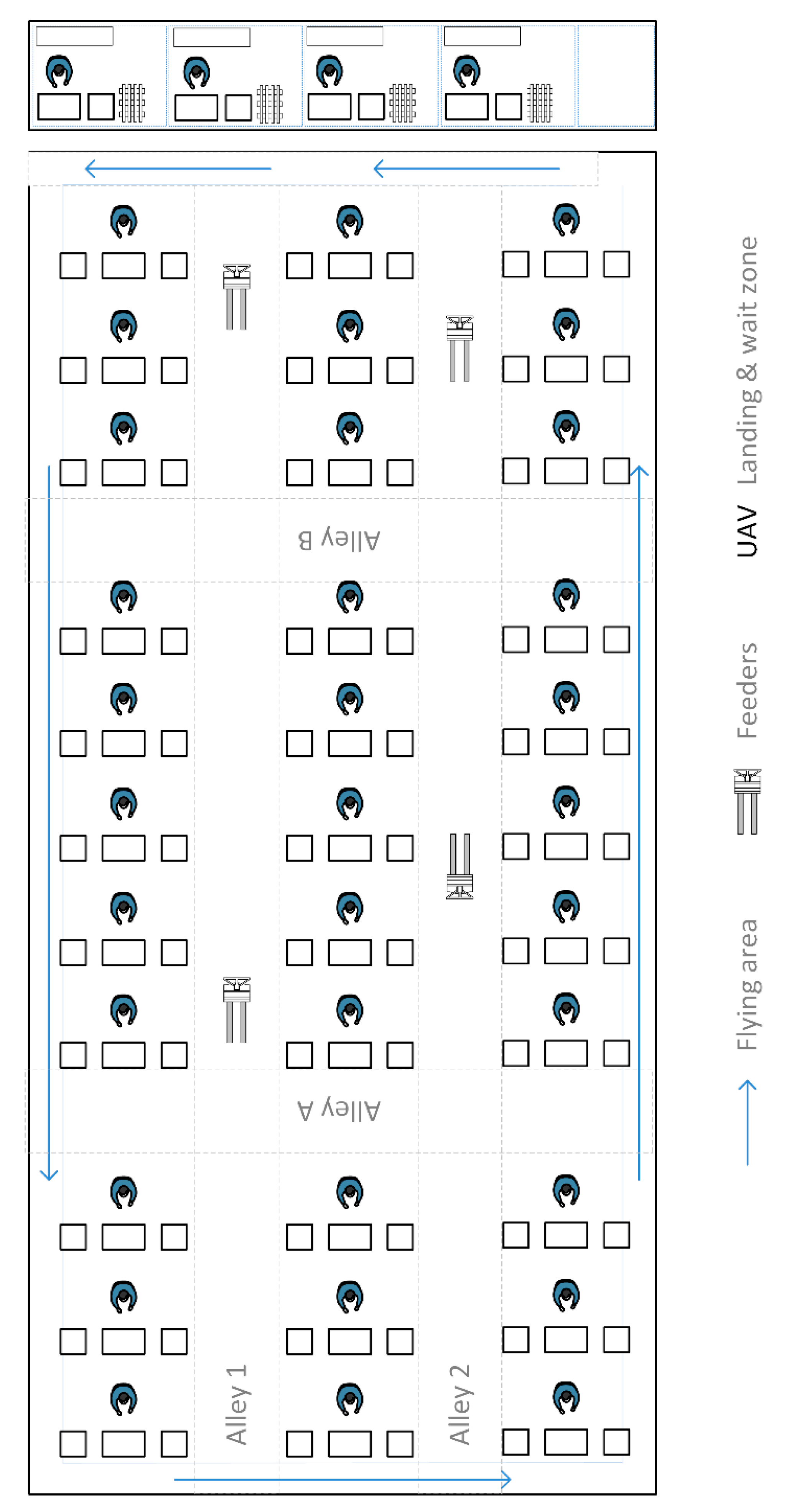
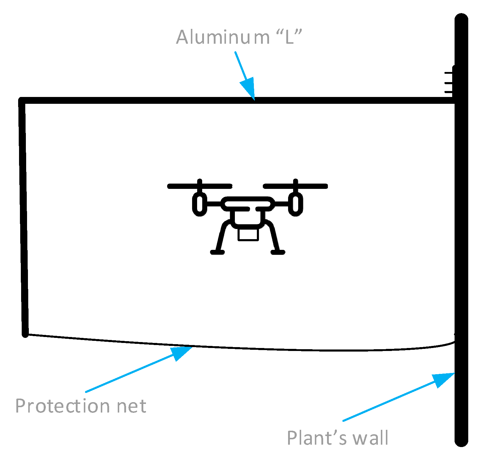
2.1. Environment

In this research paper, an unmanned aerial vehicle is used for a light manufacturing parts delivery inside a plant, without human’s intervention. For test purposes, a four copter with a cuvette underneath for small and light part transportation within the plant was used. Table 1 depicts the most significant characteristics of the UAV:
Although the proposed solution is aimed to be generic, a 190 × 100 m manufacturing plant was used for design purposes, as displayed in Figure 1.
On the top right corner, we have the UAV wait zone for the vehicle to stand-by until required for a delivery. Next to it, four team leaders prepare pallets containing the materials to be assembled in assembler workstations; manufacturing orders are received by the team leader, who prepares pallets with all necessary parts to be assembled; those pallets are taken to assembly workstations by feeders team, so that assemblers focus on assembling. Team leaders will also fetch from warehouse extra parts that might be exceptionally required by assemblers in case there is a wrong/mission part; those “urgently needed” parts are the ones to be delivered by the UAV directly to the assembler that raised that manufacturing incident.
Operators working in an assembly area can be seen in a three columns per eleven rows matrix. Every assembler has three working tables, where the left-most one is a landing table for the UAV to deliver the parts for that workstation. The UAV must navigate until finds the landing table of the assembler who raised the incident, perform a vertical landing, stop its propellers, wait until operator confirms that he has taken the part from its cuvette, to perform a vertical take-off until its cruise height, and come back to UAV’s wait zone.
The flight must be accomplished through a security flight corridor that is in the perimeter of the plant. It consists of an aluminum “L” (0.9 m width, 0.75 m tall) attached to the wall of the plant as displayed in Figure 2:
Under the “L” confined passage, a protection net is issued to prevent any accident in case there is a problem with the UAV’s flight. The net is attached to the “L” and to the wall, having openings in the vertical of the landing tables.
Abstracting the path to every workstation as a combination of a perimetral approach and a transversal translation suits the case of manufacturing plants were the workstations are aligned, distributed in rows and columns. Whenever the floor layout shows scattered workstations that are not aligned, the number of transversal corridors could potentially be too high. The maximum recommended distance from the center of a landing table to the rectilinear line that their neighbors form, would be the width of the flying corridor.

2.2. Distance Calculation

RFID positioning has been studied deeply through literature, and its challenges for obtaining an accurate distance have been already stated (as described in the Introduction). The proposal to overcome those issues and for providing UAV localization is based on the idea of RSS measurement aided by a positioning technique (bilateration), sonar readings, and a proper navigation algorithm.

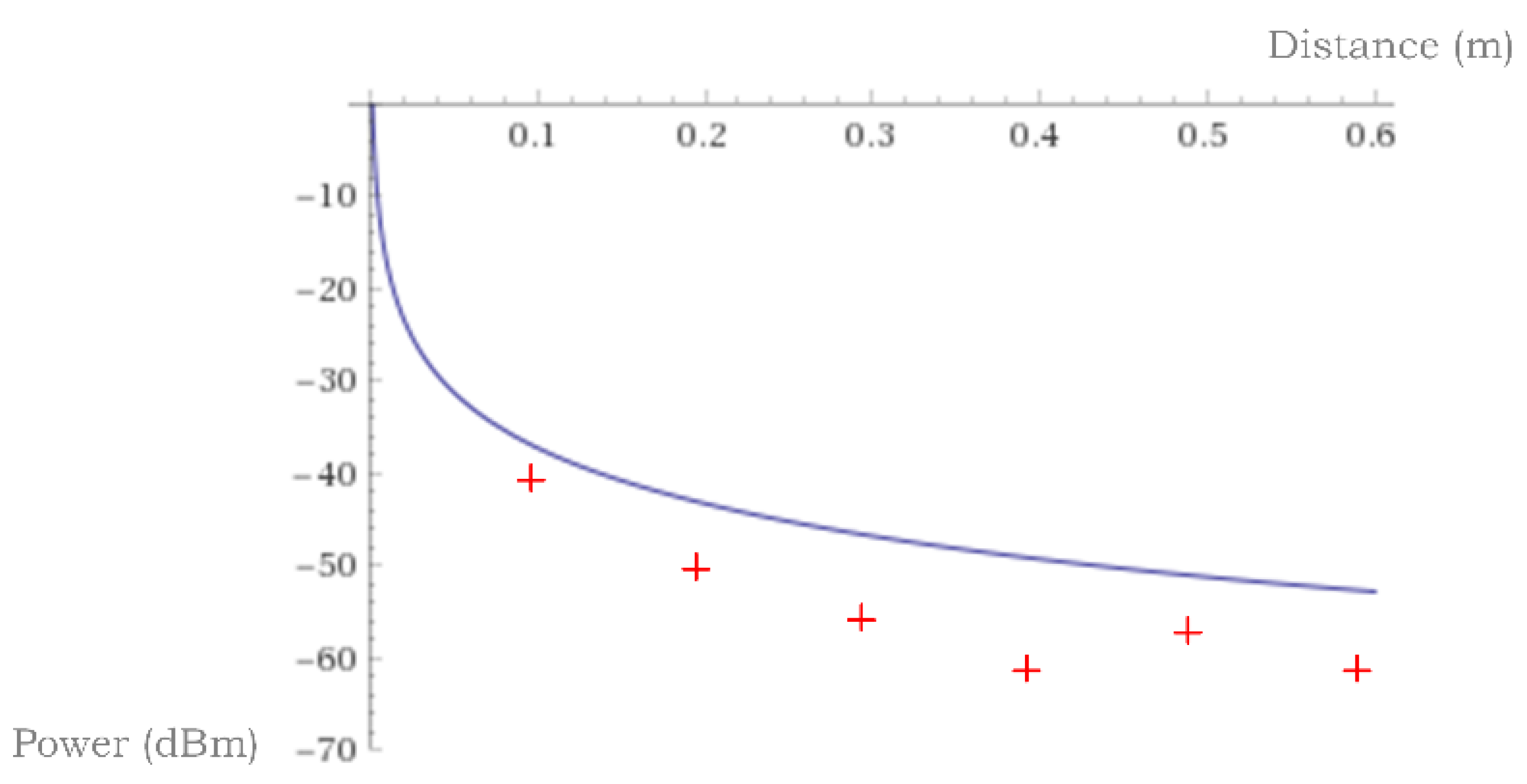
2.2.1. RSS Measurement

RSS measurement is obtained onboarding a RFID reader module and an UHF (ultra-high frequency) antenna to detect, during UAV’s progress, a series of passive tags that will be strategically placed in the “corridor” reserved for its flight. The position of the tags is known and is key to obtain better results in terms of reducing interferences between different tags and reducing multipath effect due to reflections. Figure 3 shows a plan view of the proposed method:
The UAV is flying through the perimeter corridor finding, on its course, two tags. The tags are placed left and right to avoid reflections; that arrangement and a proper distance between them allows the vehicle to receive wave fronts from the two following tags on its progression. RFID tags are placed on a 10 × 10 × 10 cm 3d-printed PTEG (poly-ethylene terephthalate glycol) wall anchor. On the front the tag is glued, so that it has direct line of sight with the onboarded reader. On the right side, the attachment on the wall is done using double-sided tape. On the back, a stainless-steel sheet coated with a radio wave propagation prevention (HSF54) is attached, in order to prevent receiving reading from surpassed tags. Confined flying “L” structure is also coated to avoid reflections and allow the reader to receive just direct readings from tags.
In free space, the power received at the antenna will be attenuated as defined in the propagation laws. Attenuation is a function of the distance to the emitter, and is explained by Friis law:
P r = P t   G t   G r L ( λ 4   π   d ) n
where Pr is the power received in the antenna of our locator; Gr is the gain of the antenna that is receiving the signal; Gt is the gain of the antenna that is emitting the radio frequency wave; λ is the length of the electromagnetic wave; d corresponds to the distance that exists, in direct vision, between both antennas; n is an experimental variable, the nature of which depends on different parameters such as the difference in height between antennas versus the wavelengths involved, and the transmission medium itself (given that the tags have been placed so that they are practically at the same height as in the drone’s flight line, and that the medium we are going to use will always be air, it is common to use a value of 2 for n); L is used to reflect the losses of the emitter–receiver set, which are not determined by the wave’s own propagation in the medium.
The Friis equation can be expressed in logarithmic power terms, as is most common when dealing with signal theory:
P r = P t + G t + G r L 10   n   log ( 4 π d λ )
Passive tags using UHF frequency have been selected, and an 871,228 MHz (located in the 860 and 960 MHz range for Gen2 tags) was the operation frequency; the corresponding wavelength for this electromagnetic radiation is λ = 0.3443   m .

2.2.2. Bilateration

Once a theoretical measure of the distance to a specific tag is obtained, the next step is to determine the distance to the other tag that is within the range and, based on them, perform bilateration, as seen in Figure 4:
The mechanism for calculating the location in two dimensions, x and y, can be found using the circumference equation. The z dimension is not really variable, since the flight altitude is predetermined to be constant, equal to the height of the confined corridor where the UAV flight must take place. Expressed in Cartesian, the distance d1 to a tag X 1 = ( x 1 ,   y 1 ) and d2 to a tag X 2 = ( x 2 ,   y 2 ) is given by:
d 1 2 =   ( x   x 1 ) 2 +   ( y   y 1 ) 2 d 2 2 =   ( x   x 2 ) 2 +   ( y   y 2 ) 2
Dixon proposed a method to obtain x and y as [68]:
x   =     v 1 + y   y 2 x 2
y =       v 2 ( x 2 ) v 1   ( x 1 x 2 ) ( y 1 y 2 ) ( x 2 ) +   ( y 2 ) ( x 1 x 2 )

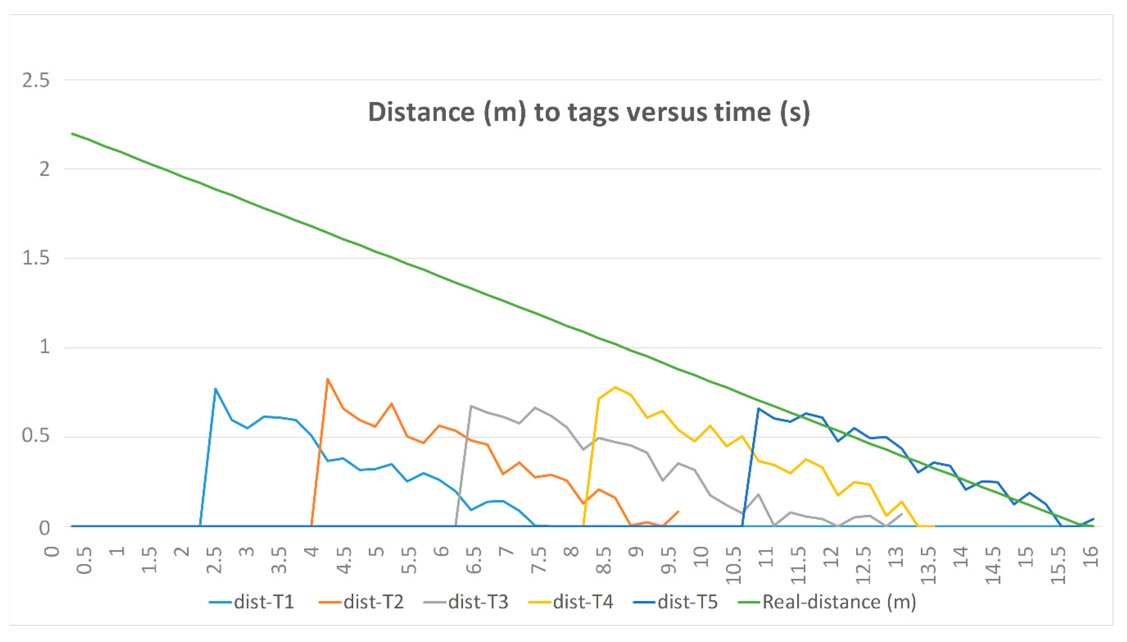
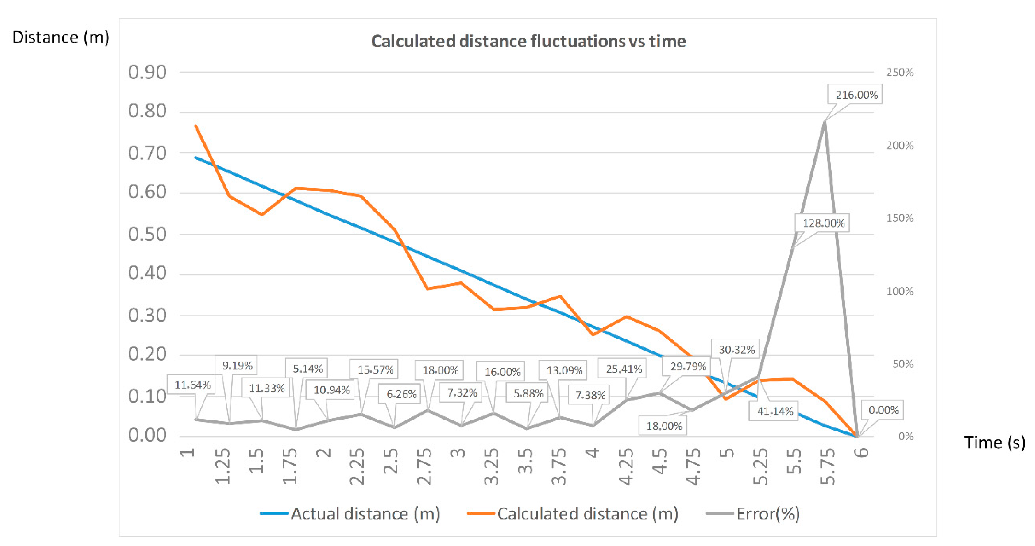
2.2.3. Second Measurement

UAVs are actually autonomous flying robots. The use of sensors is very common in autonomous robotics systems (like in robotic arms [69] or mobile robots [70]), and therefore equipping the UAVs with sensors is mandatory for the sake of positioning and collision/deadlock avoidance; combining different technologies also provides a certain redundancy in case one of the systems fails and it is a common practice, as in the aerospace world [71]. According to these ideas, and since RSS readings tend to suffer from discrepancy from the ideal model [72], a sonar sensor is added to help positioning. Selected technology has been proven in the terrestrial robotics system historical measuring distance in different ranges [73]. Five sonars corresponding to north-south-east-west and vertical (z dimension) provide distance to the walls inside confined flying corridor. Vertical sonar helps maintain the right flight level, and the other four keep the distance with respect to the walls in the confined flying corridor.

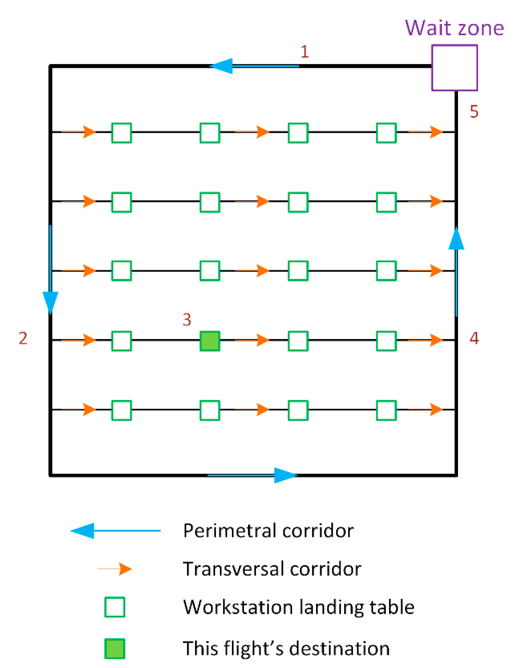
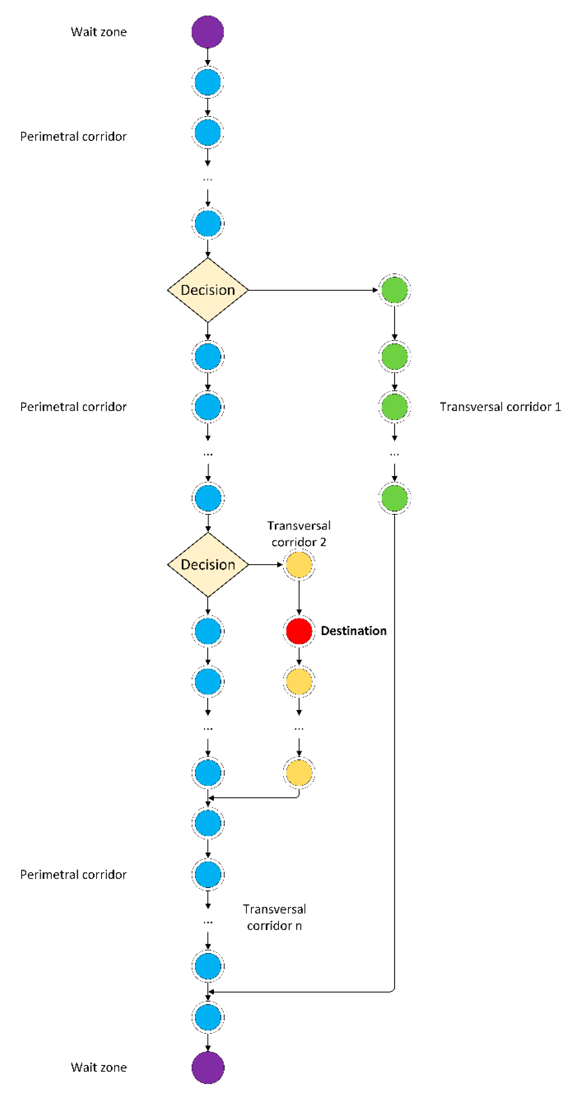
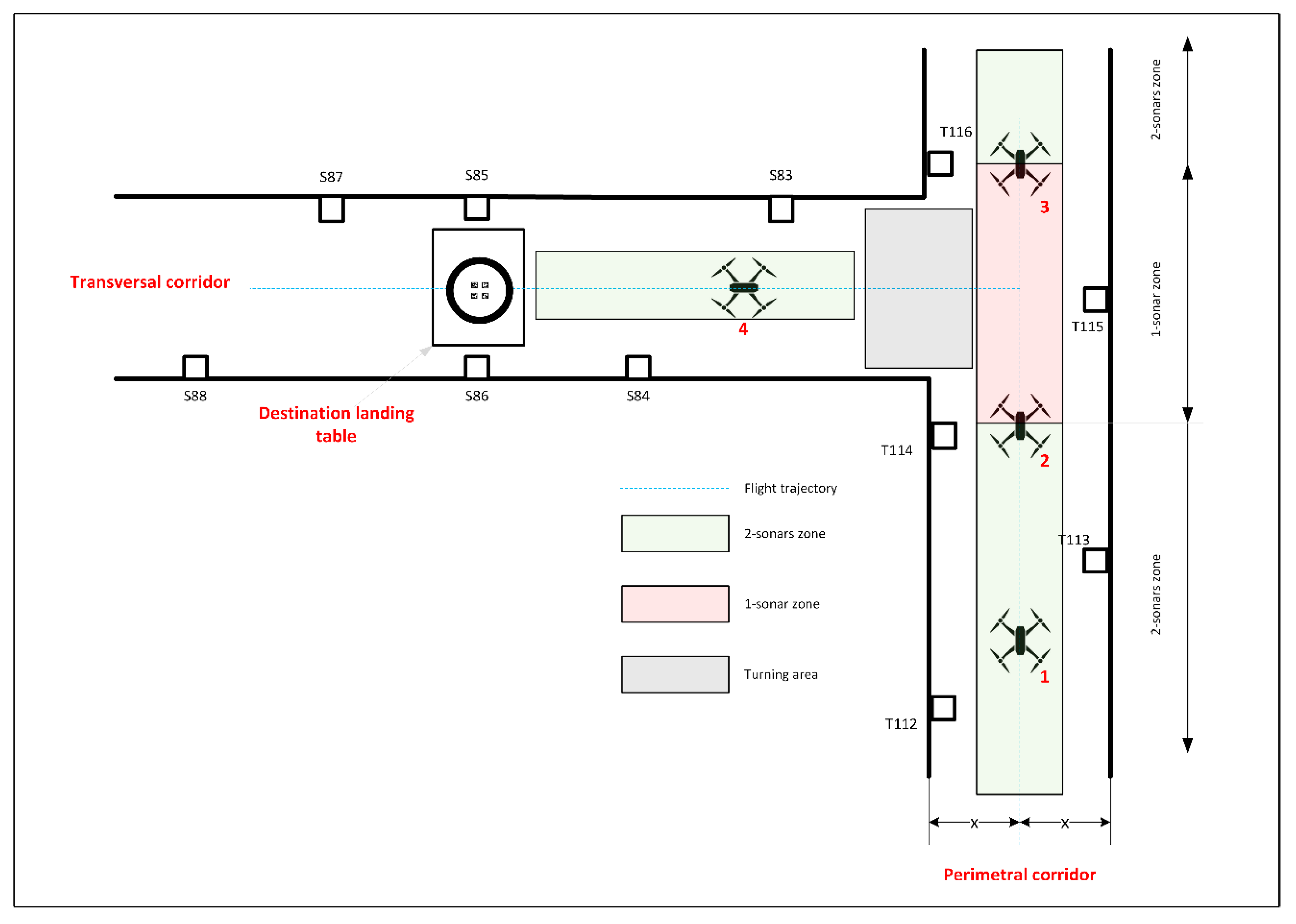
2.2.4. Navigation Algorithm

Sonar sensors working perpendicular to the forward direction of the UAV will allow keeping it centered with respect to the confined corridor. Given that vehicle’s dimensions and flying corridors are known by design, centering the UAV inside the corridor is straightforward. Flight strategy inside the plant is based on abstracting corridors and workstation landing tables (destination point) as nodes, performing navigation as shown in Figure 5:
To perform UAV’s navigation safely inside manufacturing plants, confined flying corridors with net protections are proposed. For the UAV to get to its destination carrying the load, it will climb up vertically to the flying altitude, and traverse the perimetral corridor (step 1). When it finds the transversal corridor corresponding to the landing table of the operator that raised the incident, it will perform a turn (step 2). The next steps are finding destination, performing a vertical land, waiting until the operator confirms reception, climbing again to cruise altitude, and finally getting back to its wait zone (4 and 5). The UAV will keep a centered flight inside the confined corridor, detecting tags during its course and deciding directions according to tags layout, stored on its Raspberry Pi computer. Every tag is defined as a node, to map their arrangement in memory as shown in Figure 6:
The algorithm is based on following the sequence of nodes through perimetral corridor until finding tags at the crossing between perimetral and transversal corridors, where a decision has to be taken about turning or not. In Figure 6, the destination node is on transversal corridor 2, so the UAV must turn at the second decision point, follow transversal corridor, deliver its payload at destination table, progress through transversal corridor until reaching the crossing with perimetral, and finish its journey at the wait zone again, via perimetral corridor. To obtain the shortest path to a specific goal we follow a well-known solution to this problem, that is similar to the all-pairs shortest-paths one; the idea is to use the shortest-path results calculated in previous stages to help determining the shortest paths in future ones [74], a performance oriented variation of Dijkstra’s algorithm.
Figure 7 depicts the procedure for performing turns to (and from) transversal corridors:
Over the course of most of the corridors, the UAV is having line of sight with two tags at the same time. UAV at stage 1 detects tags T113 and T114 providing location, and has two sonars (left and right) providing accurate centering, keeping the same “x” distance with respect to both sides of the corridor; it is within the 2-sonars zone. When it progresses to stage 2, only one tag (T115) is reachable, as predicted by node map. When it loses left sonar readings (the next wall is out of range), the algorithm must evaluate if a turn is required to follow the right path towards destination. If it is not the case, the UAV will keep flying straight, maintaining the same distance as the average value from previous leg, using sonar readings; it is within the 1-sonar zone. Afterwards, the tag at the intersection with the transversal corridor (in this case, T116) will be visible, announcing that 1-sonar zone is about to finish; when reading from left sonar come back to values within range, it will be confirmed that UAV is back at 2-sonar zone (stage 3), similar to stage 1. In the case that, being at stage 2, the algorithm requires a turn to reach transversal corridor, a left turn is performed at the beginning of the 1-sonar zone. At that moment (stage 4), navigation is similar to the one at perimetral corridor; at the end of transversal corridor the next turn will take the UAV back to the perimetral again, to resume to its wait zone.
While on stage 4, UAV progresses through the transversal corridor until it reaches the tags corresponding to the landing table where its load has to be delivered (in Figure 8, S85 and S86). Getting passed previous tag in the nodes list will be the sign to reduce speed up to 30%, until the hole in the net is reached and the landing table is seen from the UAV. At that moment, it will descend vertically using vertical sonar to control distance to the table, and the visual marks in the table to center descent, as seen in Figure 8:

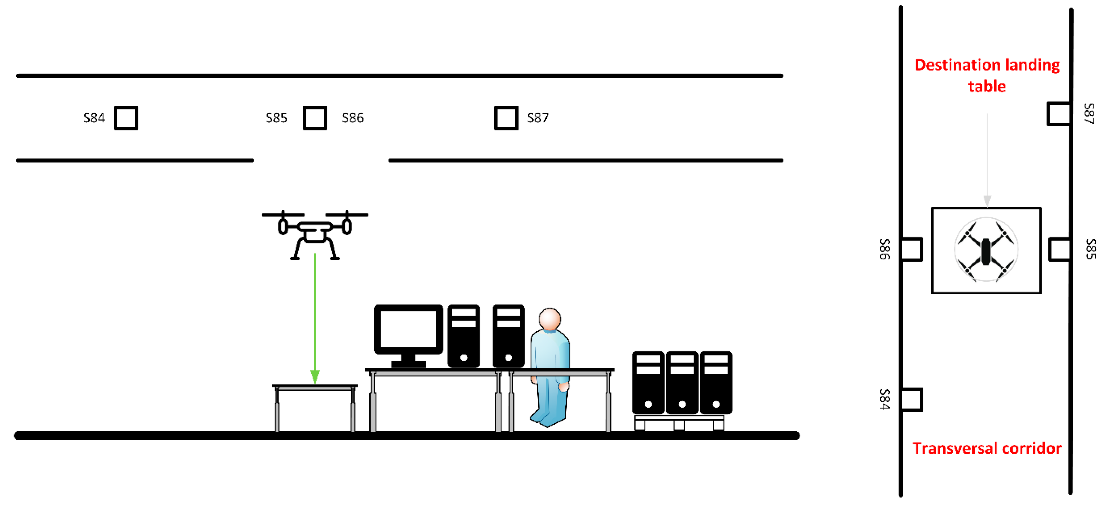
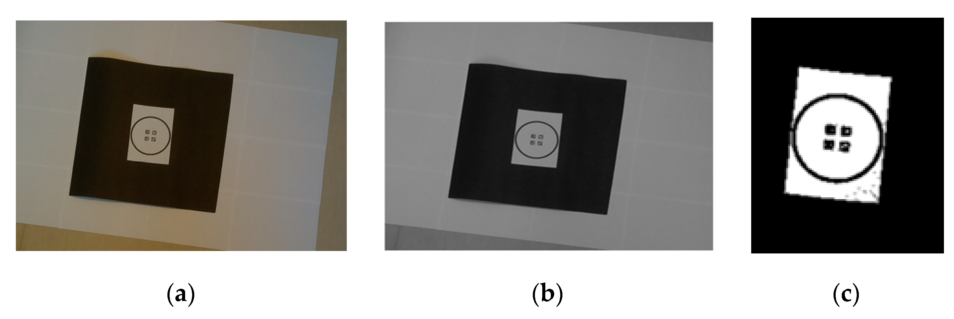
2.2.5. Computer Vision Landing Operation

Once the UAV reaches the opening area in the flying corridor, marked by its tags, it will activate the camera to begin recognition. Proposed markers on landing table include a circle for long-range recognition and a set of four ArUco marker for short range, as depicted in Figure 9:
The dimensions of the circle allow its visibility from the flying corridor, and the long-range part of the descent; when the UAV approaches the landing table, the circle is not visible, and the ArUco markers provide control at this stage. The following steps are defined for landing:

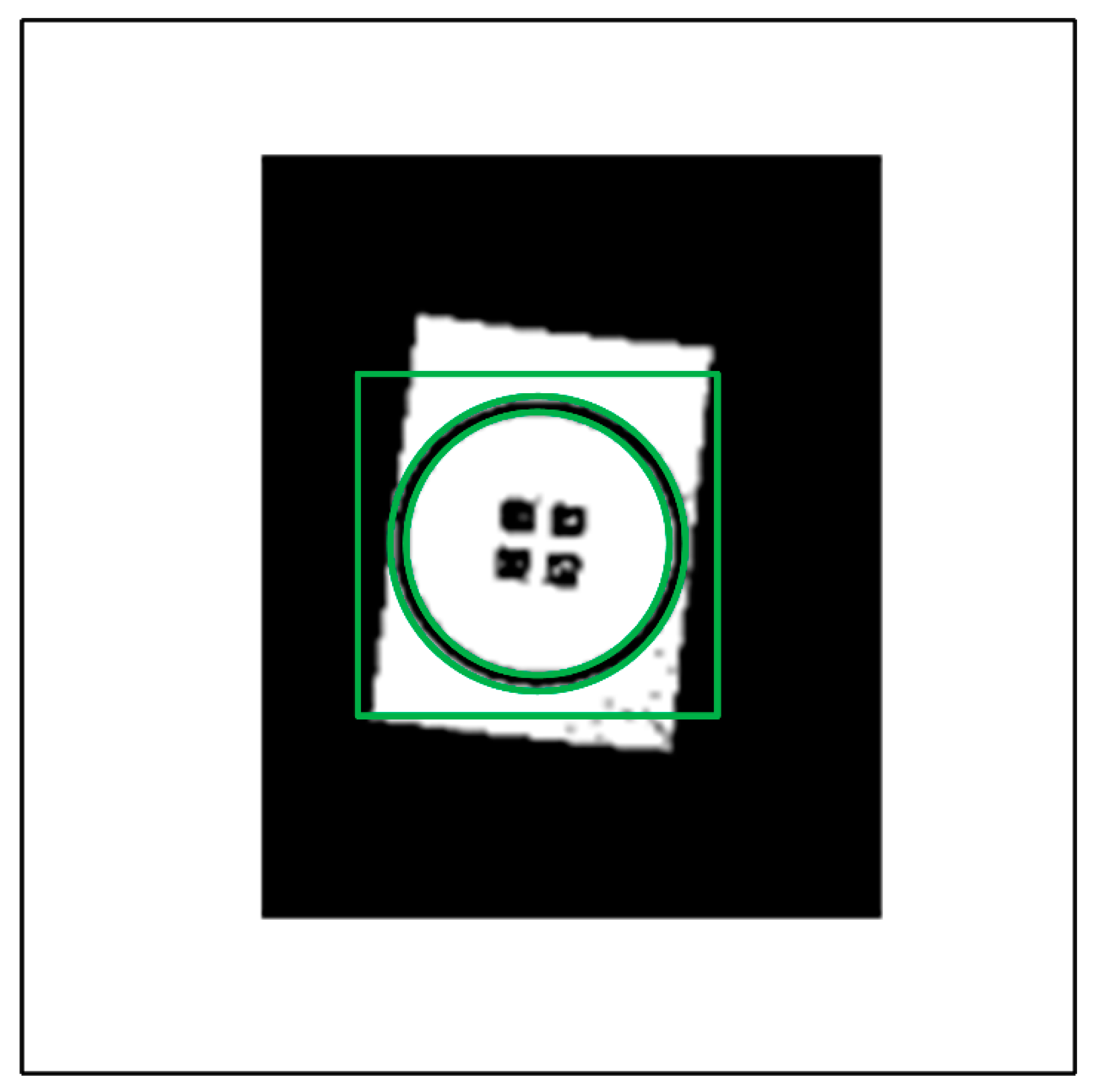
Finding the Opening at the Corridor to Begin Descent

At this step at the transversal corridor, the first requirement is to determine the point where descent must begin. While progressing through the corridor, sonar is not operative in the forward direction and RFID suffers from certain error. Fiducial markers in the landing pad of the workstation table, vertically aligned with the descent point, will be looked for and used to determine where UAV should begin descent; consequently, we need to control the x axis. The OpenCV library is used to alter the image from RGB to greyscale using discrete values from 0 to 255, and then convert it to a black and white binary image. It is morphologically transformed then to eliminate image noise and extract the contours and silhouettes of the shapes found in an opening operation (erosion and dilation processes).
Next steps are aimed to determine whether detected elements in the image correspond to a circle, as described in [75]: aspect ratio (AR) and solidity (SL) should have values similar to 1, and extension similar to π 4 . The aspect ratio is the quotient between the width and the height of the shape; the solidity is the quotient between the areas of the contour and the convex hull (the convex perimeter around the points of the circle); finally, the extension refers to the quotient between the areas of the contour and the bounding box around it. When the circle shape is confirmed, the center is obtained, and the distance to it (x, y) is determined; given that left and right sonars are keeping the UAV centered in the corridor, a value of x = 0 distance will determine descent point. We must transform the distance in pixels to meters, using the pinhole camera model [76]:
d x = K ·   x =   D d ·   x
where D is the diameter of the real circle and d is the diameter in pixels; dx is the distance to the descent point.

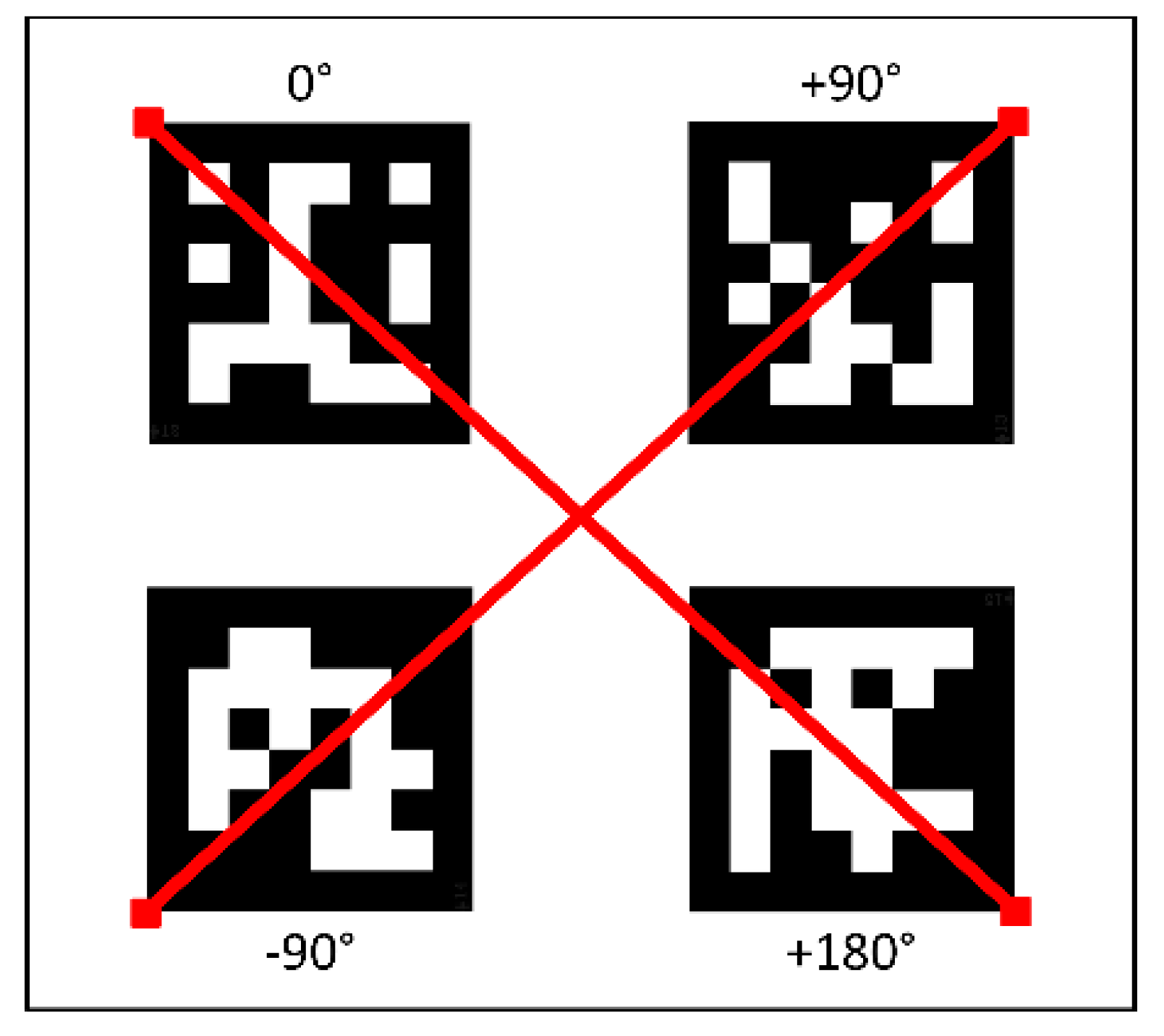
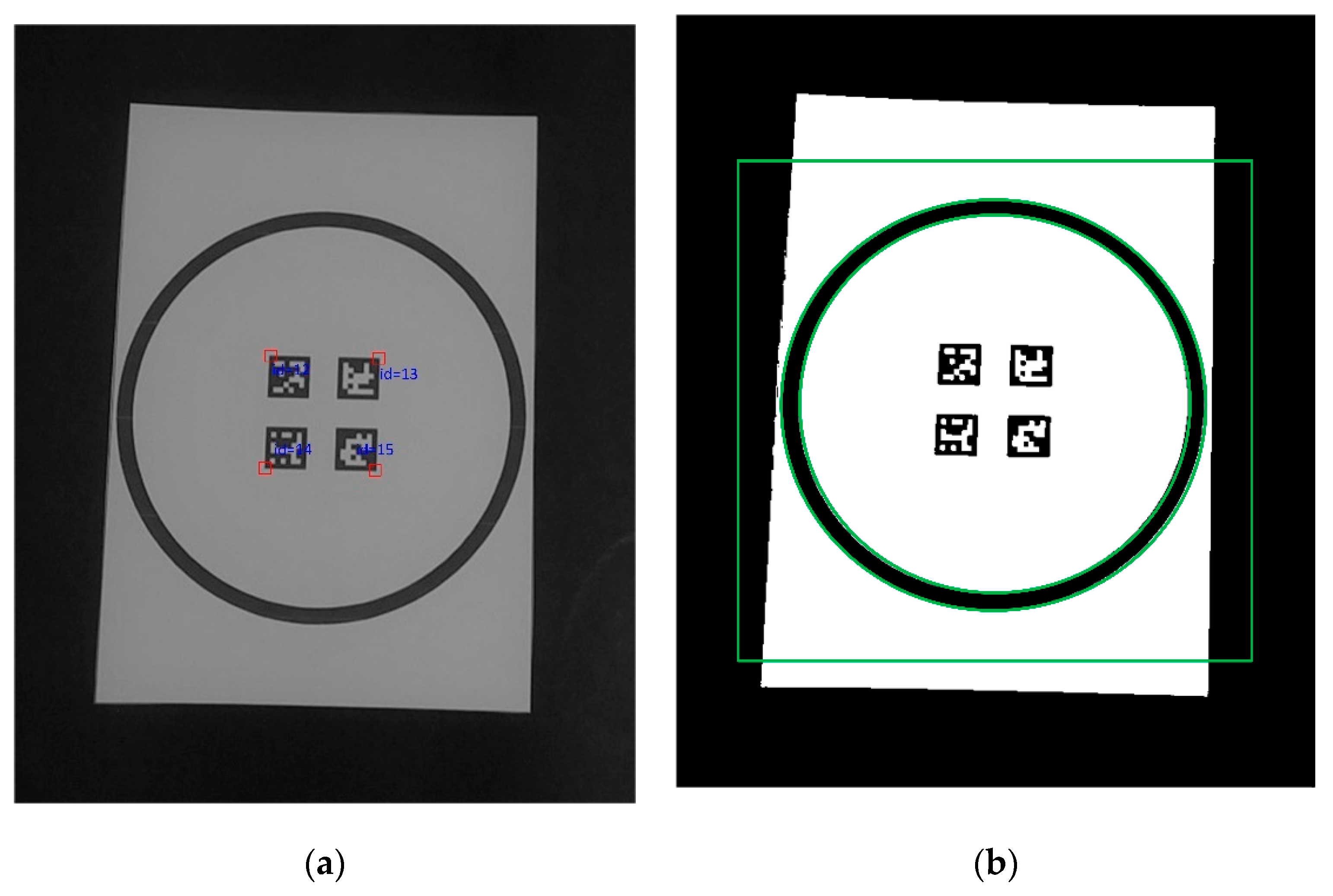
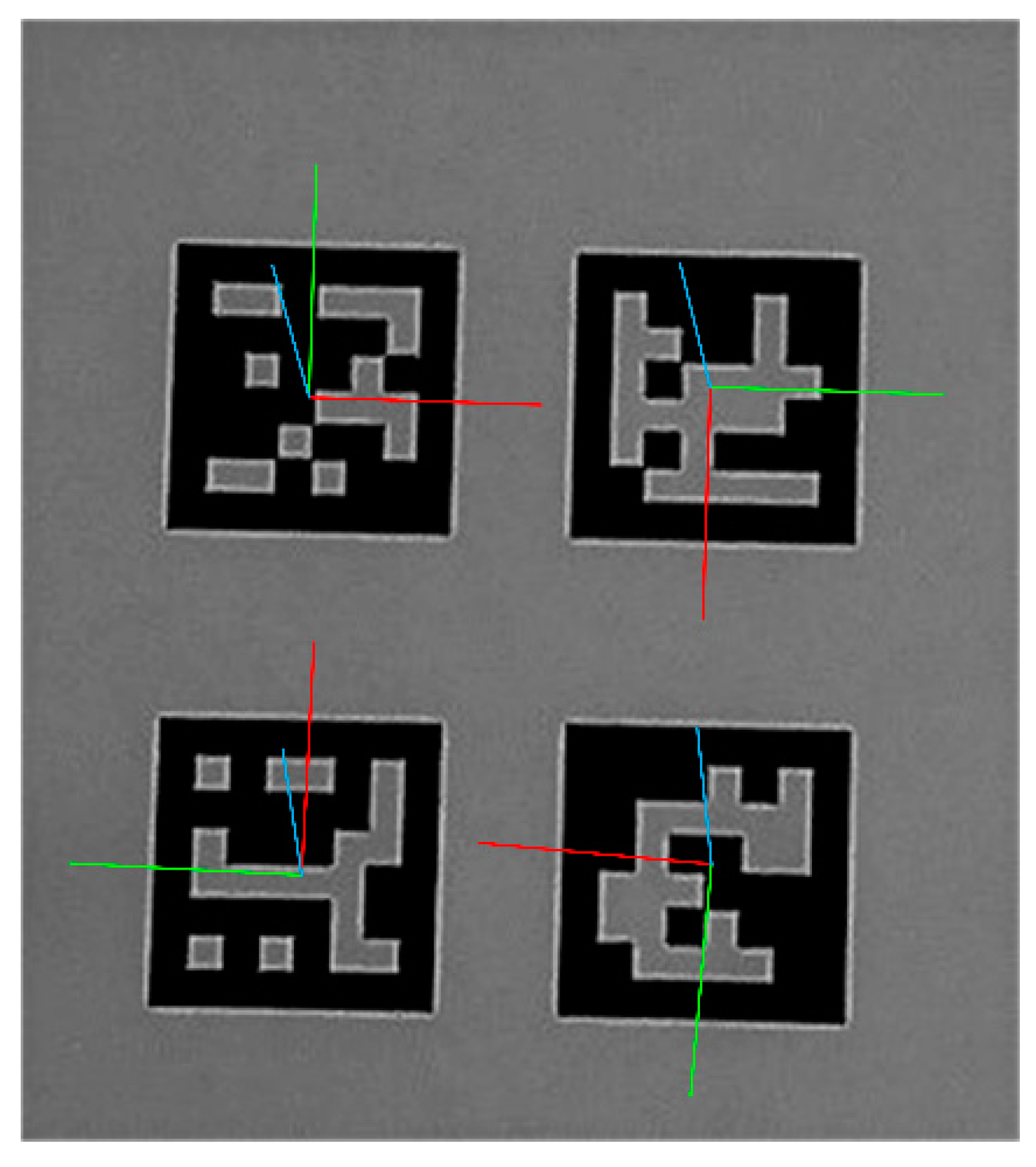
Finding the Short-Range Markers

The UAV performs descent controlling the z variable with sonar until gets out of the flying corridor; when the ArUco markers become visible, they will be used for short-range descent, where the size of the outer circle gets out of sight; after some tests, the sizes of the markers and the circle are chosen to have constant positioning. Whilst one ArUco marker can provide pose estimation for the UAV [77], in this research four are used to: (a) use a fusion algorithm that conveniently combines the information from them; (b) provide another mechanism to obtain desired landing point, as the intersection of the two diagonals that form the top-left squares of the markers, as shown in Figure 10:
In this case, the image is transformed to a greyscale, detection of its contour is performed, and a polygonal approximation is made [78], resulting in every item having binary value due to the threshold limit. Marker’s unique identifier confirms that it is one of the four selected ArUco items, and consequently recognition is confirmed.
The next step is to solve the well-known PnP problem (pinhole camera model), to describe the projection of a point from the 3d world coordinate system to a 2d image model, [79], as seen in Figure 11:
For a point p in the real-world coordinate system { W } centered at w0, the PnP model finds its projection on the image plane, represented by the imagen coordinate system { I } , through the camera coordinate system { C } (this is, PnP maps a three-dimensional scene to a two-dimensional image, in an image plane). It is a three-step procedure that first transforms the coordinates of p into the camera coordinate system (using a rotation plus a translation), then the point p is projected to the image plane (using the camera focal length), and finally the coordinates in the image coordinate system are discretized (considering the size of each pixel in the CCD, the charge-coupled device of the camera) [79].
There are several solutions in the literature for the PnP problem, and the Efficient PnP (EPnP) [81] was selected for its efficiency that allows performing the algorithm with four ArUco markers at a time. A linear system is generated as:
M   x = 0
where x is the transposed vector of unknows and M is the matrix that combines camera intrinsic calibration matrix, the 2d projections of the reference points, the scalar projective parameters, the 3d coordinates of the n control points; the method simplifies the complex problem by expressing the 3d points as a weighted sum of four virtual control points [81].
Since four markers are used, fusion estimation is performed to combine the four pose estimations into a more accurate one. The problem is within a general multisensor linearly weighted estimation fusion case, that extends the Gauss-Markov estimation to the random parameter under estimation [82]; in our case, given that mj are the pose estimations (for j in the 1–4 interval) and r’ is the unbiased estimate for m as:
r = w 1 m 1 +   w 2 m 2 +   w 3 m 3 +   w 4 m 4
where wj represent the weights to be calculated. Using the Lagrange multipliers, the variance is minimized when [83]:
w j = 1 V a r ( m j ) j = 1 4 1 V a r ( p i )
The kinematics and dynamic model for this type of UAV has been intensely studied in the literature [84,85]. In Figure 12 a simplified representation of the quadcopter is shown, with the four thrust vectors T1–T4 generated by the electric motors. A body fixed reference system {B}, centered on the UAV and attached to its structure, defines the attitude of the vehicle, using the roll, pitch, and yaw angles (φ, θ, ψ). A world reference system {W} helps define the position of the UAV as P W = ( P x W ,   P y W ,   P z W ) .
Accordingly, defining g as the gravity acceleration, m as the mass of the vehicle, and fb as the force applied to the drone in the body fixed reference system, the dynamics can be written as [86]:
P ¨ x w =   f b m   ( sin ψ +   θ cos ψ )
P ¨ y w =   f b m   ( cos ψ + θ sin ψ )
P ¨ z w =   g f b m   cos θ
Once the computer vision system provides the actual location (xa, ya, za) and yaw angle (ψa) of the destination using OpenCV, they are injected in two standard PID (proportional integra derivative) controllers: one for controlling position (considering the desired destination point), and the other for the attitude control (fed by desired yaw angle, and the result of position controller). The result is injected in the multirotor speed controller to regulate the electric motors. The PID gains were adjusted in preliminary tests to obtain a smooth trajectory.

2.2.6. Communication

Zigbee provides an affordable communication mechanism for deploying a wireless network in the manufacturing plant, capable of deliver messages between UAV and the backend software. A mesh network is proposed to send UAV location to the backend, and to receive commands. In Figure 13, the proposed Zigbee node deployment is depicted:
Taking advantage of the presence of operators’ workstations in the plant, a Zigbee node will be deployed in each of them. Keeping visual line of sight between workstations allows messages to be forwarded along any standard manufacturing plant. In the figure, the green node represents UAV’s onboarded Zigbee node, progressing through flying corridor. Light blue nodes represent on-the-ground Zigbee node, that retransmits messages. Should any node be inoperative (red node), the network itself updates routing to guarantee message delivery, using the shortest operative link at any specific time. Dark blue node (one network coordinator per PAN) manages the network and is also connected to the wired LAN (local area network); consequently, it will forward every message between wired and wireless networks.

2.3. Setup

Proposed method was tested in the laboratory using onboarded and on-the-ground systems with the following hardware, displayed in Table 2 and Table 3:
RFID module reader is a small sized (57 × 37 × 7 mm), low weight (112 gr), low power consumption (0.15 to 5 W) UHF device, with transmission capabilities up to 30 dBm. It provides two external interfaces: the antenna connector, and UART pinouts for microcontroller communication. The UART to USB adapter is plugged to the Raspberry Pi (on the USB side), and to the RFID reader (on the UART pins). Winnix antenna is a UHF compact (130 × 130 × 21 mm) lightweight (210 gr) ABS product with a net 4 dBi gain, that interfaces with RFID module reader. Selected sensor is a MaxBotix 1232 IC2 small (<22 mm) lightweight (6 gr) ultrasonic sensor, emitting a narrow beam with one-centimeter resolution in its 20–765 cm range; it supports I2C for an easy communication. Raspberry Pi allows handling computer vision and communication and calculating positioning; it is connected to the flight controller via serial connection. NoIR camera is a lightweight compatible solution to be used for capturing frames for landing operations. Zigbee communication is provided by a Xbee PRO module, which fits over the Zigbee USB adapter, that is plugged to one of the four Raspberry Pi USB ports.
On the ground, every workstation is to be equipped with a Raspberry Pi computer to become a forwarding node in the mesh architecture. Every node should at least have visual line of sight with another workstation for the mesh to be able to forward messages.

3. Results and Discussion

3.1. Positioning System
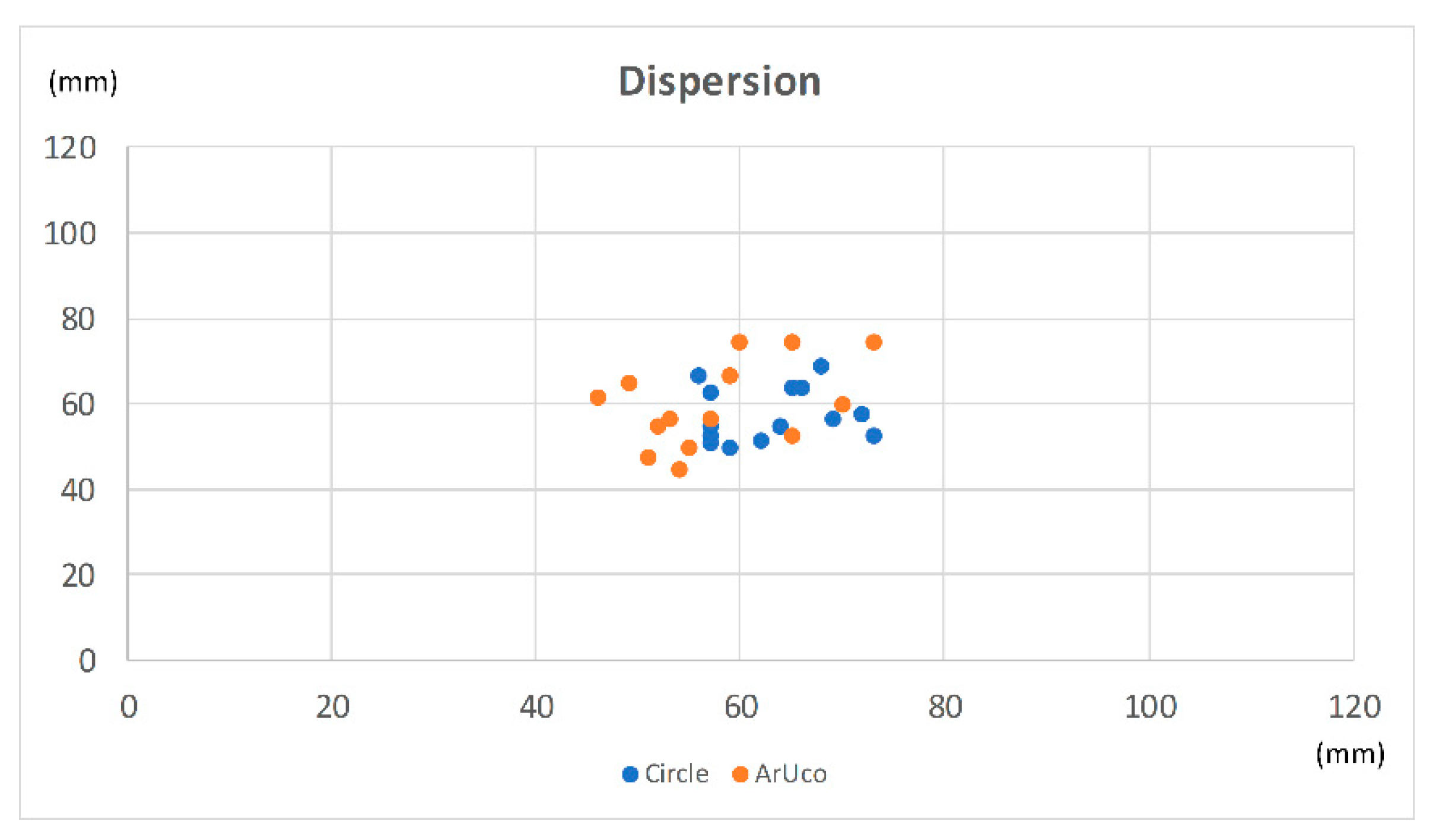
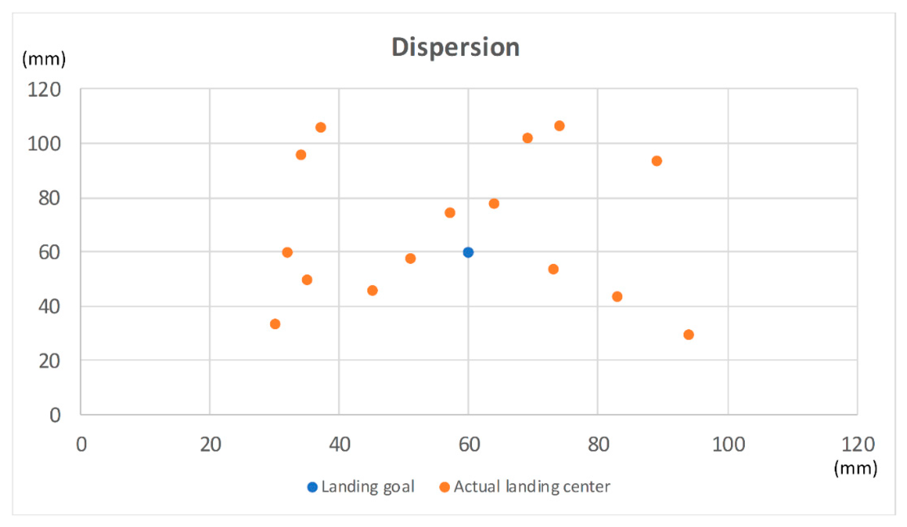
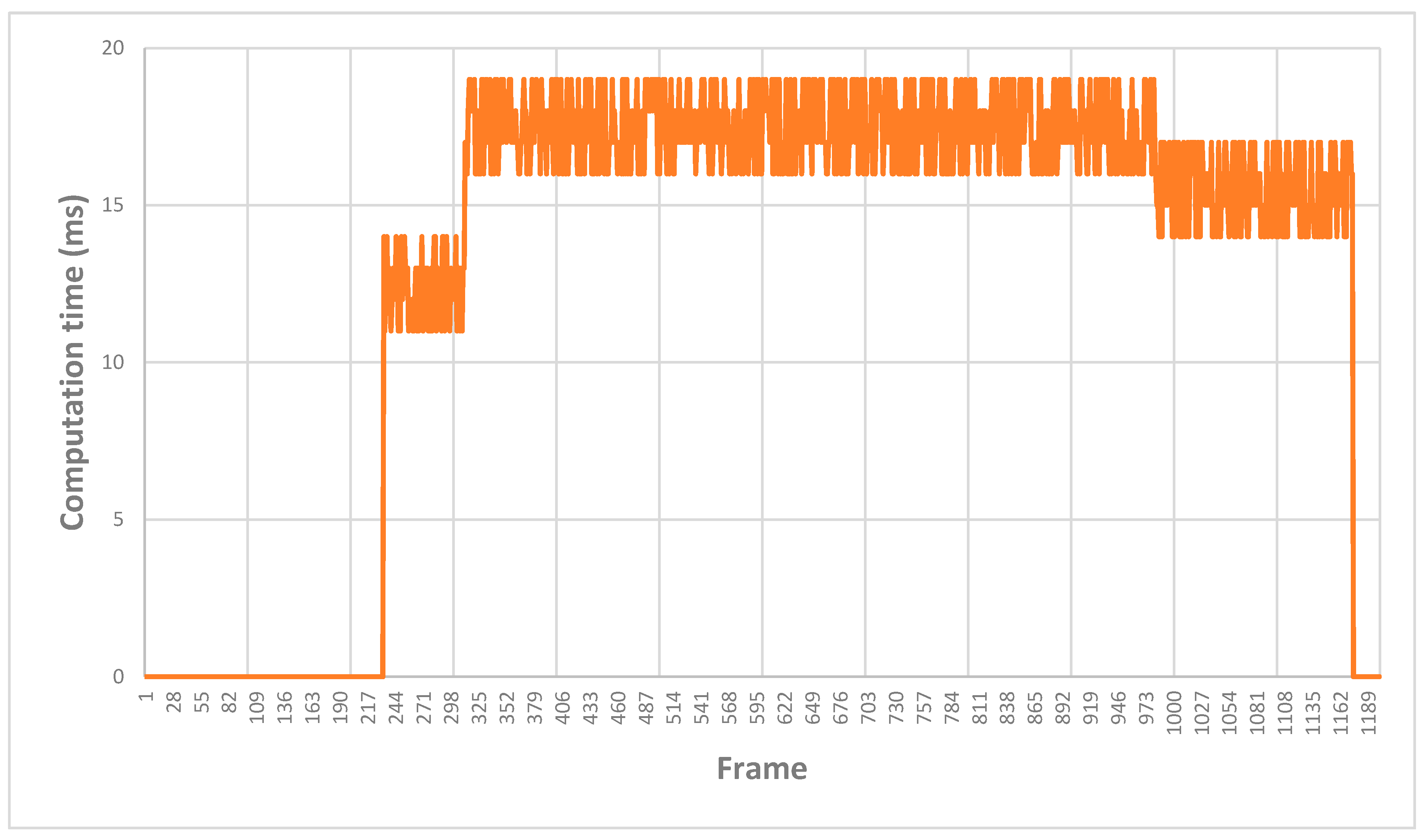
Using the specifications given by chosen hardware manufacturers, Equation (2) can be written as:
P r = P t + G t + G r L 10 ·   n · log ( 4 π d λ ) =   30 + 4 10 · 2 · l o g ( 4 π d 0.3443 )
First experiment is for evaluating the value of n in Equation (2), that provides a relationship between distance and power received. An isolated tag was initially put at 1.5 m distance from reader in the laboratory, with no other tags present. Power values were registered ten times, at twenty second intervals to provide an average value for that distance. The experiment was repeated 15 times, each time reducing the distance 10 cm. In Figure 14, the theoretical model is represented; the figure also displays average real power values from experimentation:
As it can be seen, the theoretical curve must be adjusted to fit real data. Using a value n = 2.6, we have a reasonable match between the fitted model and real values, as seen in Figure 15:
Consequently, the final model can be expressed as Equation (14) shows:
P r =   26 26 · l o g ( 4 π d 0.3443 )
Once a definitive model is achieved, another experiment is performed, to test localization in the laboratory. Five UHF passive tags representing perimetral corridor were located as shown in Figure 5. The reader progressed through it, while logging calculated distance using the model. Figure 16 displays (green) real distance measured with sonar, and the calculated distances to the five test tags. The experiment was repeated ten times and the values shown are the average:
The figure shows how, at every moment, at least two tags are providing distance readings, and consequently giving location with respect navigation nodes.
As expected, distance values suffer certain fluctuation with respect actual values. Figure 17 displays sonar readings (blue) versus average calculated values (orange) when using RSS from a tag (repeating the experiment ten times again):
Figure 17 displays percentage error as well, between calculated and actual distance. Two points at small range can be considered outliers because of the extraordinary difference with respect to actual values. Table 4 depicts those error values including all points (all), or eliminating outliers:

3.2. Landing System

The landing procedure was tested in the laboratory floor using a 0.9 × 0.9 m MDF black board as landing table on a 3 × 3 m white bed, and the proposed landing pad marker in the center of the table. It was repeated 15 times and each iteration was split into three steps:
The first step is long range landing pad detection, as shown in Figure 18:
Reasonable results were obtained for the location of the landing center as displayed in Figure 19; the circle was recognized and kept with visual range in every iteration, and every captured frame obtained its bounding box, ellipse approximation, and center calculation:
The second step is to obtain positioning from both methods for when distance to the landing pad keeps the circle in visual range and the inner markers enter visual range as well. Once the UAV leaves transversal corridor height, the ArUco markers will become visible, as shown in Figure 20:
Consistency between the two previous methods was checked to evaluate the discrepancy of the (x, y) coordinates location given by both. Average absolute calculated error among the 15 sets of values where 7 mm for the x coordinate, and 8 mm for the y coordinate. Coordinates are represented in Figure 21, showing an acceptable discrepancy between the values:
The third step is for close range positioning, when UAV’s height is low enough as to lose sight of the outer circle and perform pose estimation and locate landing point just with ArUco markers. Algorithm stops circle detector after 100 continuous frames with no circle obtained. Figure 22 displays OpenCV’s coordinate reference systems for each of the markers, according to their rotation:
Finally, once landing was finished, the landing spot was compared to the real intersection between ArUco marker’s top left corner; as a landing spot it was considered vertical from the camera, and the distance in (x, y) coordinates was measured as displayed in Figure 23. The average absolute error in the x coordinate was 19 mm, and 23 mm for the y coordinate:
A certain interference with landing table is affecting the last centimeters approach, as a ground effect, generating horizontal x and y displacements when the UAV is about to finish landing; ground effect is expected to be affecting the dynamic of the operation as it has been already discussed in the literature [87]. Since laboratory results are within acceptable error, this issue has not been addressed within this research.
All image processing takes place at the on-boarded Raspberry computer, that performs the computer vision algorithm. Figure 24 shows computation time during landing procedure, where four different stages can be seen. First, the camera is not active, while in the flying corridor. Second, when the camera is activated, in the vicinity of the opening of the corridor, and it is searching the long-range marker. Third, when the circle is detected, the long-range algorithm is controlling descent, and the short-range markers are looked for. Four, when the ArUco markers are found, and the short-range algorithm is performing the descent until landed. Computing time stays under 19 ms even in the period where the two algorithms (long and short range) are working simultaneously.

4. Conclusions and Future Work

In this research, a positioning system and a landing system are defined for an indoor light part delivery UAV within a manufacturing plant, providing a mesh network for WIFI communication with the back-end software that manages the operation. The scope for the activities of the aerial vehicle is within the perimeter of the plant, where no wind-gusts conditions are expected. The research has considered the drone for internal logistics operations, although other factory activities such as automatic inventory or surveillance could be also be appliable with the same positioning and landing system. The overall control of the UAV is provided by an onboarded Raspberry Pi, performing localization, computer vision for landing, and communication. The System on Chip computer is also providing nodes for the mesh network on the ground as well forwarding incoming command messages for the UAV and outgoing location telemetry from the flying vehicle.
As for localization, a combination of RFID, sonar, and a proper definition of flying corridors with operator’s safety in mind is done. The conjunction of the three elements provide a solution to avoid the well-known problem of RSS readings. Sonars provide accurate distance to the confined flying corridor and keep the UAV centered in the right track. An improved mechanism to deploy tags, and the use of a specific coating to prevent reflections help evading the multipath problem; consequently, the whole solution the initial lack of accuracy of RSS positioning method, and the average error and RMSE are kept within acceptable values. Manufacturing plant layout is abstracted by representing it as a series of nodes, and an improved performance algorithm is used to allow finding operator’s workstation. Horizontal flight planning has been simplified as a graph of perimetral and transversal corridors, what also allows providing required safety network for operators’ safety. Nodes’ graph and tag distribution are kept in the onboard Raspberry Pi computer to provide autonomous flight. Laboratory experiments showed reasonable results for keeping UAV’s location under back-end software control.
As for autonomous landing, an affordable computer vision is designed to provide long-range and short-range localization of the landing pad and pose estimation. Descent is split into three different steps. First, finding the point where transversal flying corridor must be left; a long-range detection of a circle helps determining when the UAV should stop going forward, and begin descent; descent begins and continues until the short-range detection mechanism, based on four ArUco markers, is within reach. Second, performing most of the descent using the short-range algorithm, while keeping the long-range still active to double-check destination point; fusion estimation is used to leverage the existence of more than one element and provide a better estimation; we even take advantage of marker’s arrangement and orientation, to obtain another reference (diagonal intersection); laboratory experiments provided acceptable discrepancy between these complementary method. Finally, the last stage uses only the ArUco markers to perform short-range approximation to the landing table; experiments show a reasonable difference between landing goal and actual landing spot.
There are still many relevant fields to be further investigated and improved. First, a single UAV is considered to be flying in this research, but it is expected that, according to the number of incidents to be attended concurrently, more than one flying vehicle needs a suitable mission control and the management of path intersection, as well as a system to regulate which UAV is attending each of the incidents raised. Second, the capability of the vehicle to attend more than one incident in a flight; in this research one flight was considered to attend one incident, but it could be improved by delivering to more than one workstation in a single run; payload’s characteristics should be taken into consideration so that the system could decide when two parts could be delivered together. Third, ground effect should be addressed; it was visually observed in the experiments that when the UAV is just a few centimeters far from ground, horizontal displacements were suffered, resulting in worst results than the ones achieved in the rest of the descent; the particular dynamics when the vehicle is about to perform landing should be added to improve landing accuracy. Fourth, the challenges that would arise when applying this methodology to a case where the UAV should perform activities inside and outside the manufacturing plant are also an interesting continuation for this research, that focused on in-door activities.
It is expected that these next steps can be taken in the near future to extend the coverage of the research already performed.

Author Contributions

Conceptualization, P.O.-C. and C.U.; Investigation, P.O.-C.; Methodology, P.O.-C. and C.U.; Project administration, P.O.-C. and G.R.-G.; Writing–original draft, P.O.-C.; Writing–review & editing, P.O.-C., C.U., G.R.-G. and J.A.P.G. All authors have read and agreed to the published version of the manuscript.

Funding

The authors received no funding for this research.

Conflicts of Interest

The authors declare no conflict of interest.

References

  1. Yang, Z.-X.; Zhang, P.; Chen, L. RFID-enabled indoor positioning method for a real-time manufacturing execution system using OS-ELM. Neurocomputing 2016, 174, 121–133. [Google Scholar] [CrossRef]
  2. Ito, Y. An indoor hybrid blimp logistics drone provided with crash-free ability at full power-loss condition. In Proceedings of the 11th International Airship Convention and Regatta, Bedford, UK, 19–21 October 2017. [Google Scholar]
  3. Otto, A.; Agatz, N.; Campbell, J.; Golden, B.; Pesch, E. Optimization approaches for civil applications of unmanned aerial vehicles (UAVs) or aerial drones: A survey. Networks 2018, 72, 411–458. [Google Scholar] [CrossRef]
  4. Yoo, W.; Yu, E.; Jung, J. Drone delivery: Factors affecting the public’s attitude and intention to adopt. Telemat. Inform. 2018, 35, 1687–1700. [Google Scholar] [CrossRef]
  5. Chipade, V.S.; Abhishek; Kothari, M.; Chaudhari, R.R. Systematic design methodology for development and flight testing of a variable pitch quadrotor biplane VTOL UAV for payload delivery. Mechatronics 2018, 55, 94–114. [Google Scholar] [CrossRef] [Green Version]
  6. Liu, M.; Li, H.; Zhai, H.; Mingzheng, L.; Hongjian, L.; Hualei, Z. Unmanned aerial vehicles for logistics applications. In Proceedings of the 33rd Chinese Control Conference, Nanjing, China, 28–30 July 2014; pp. 8299–8303. [Google Scholar]
  7. Grippa, P.; Behrens, D.A.; Wall, F.; Bettstetter, C. Drone delivery systems: Job assignment and dimensioning. Auton. Robot. 2018, 43, 261–274. [Google Scholar] [CrossRef] [Green Version]
  8. Kuru, K.; Ansell, D.; Khan, W.; Yetgin, H. Analysis and optimisation of unmanned aerial vehicle swarms in logistics: An intelligent delivery platform. IEEE Access 2019, 7, 15804–15831. [Google Scholar] [CrossRef]
  9. Yadav, V.; Narasimhamurthy, A. A heuristics based approach for optimizing delivery schedule of an Unmanned Aerial Vehicle (Drone) based delivery system. In Proceedings of the 9th International Conference on Advances in Pattern Recognition (ICAPR), Bangalore, India, 27–30 December 2017; pp. 1–6. [Google Scholar]
  10. Narkus-Kramer, M.P. Future Demand and Benefits for Small Unmanned Aerial Systems (UAS) Package Delivery. In Proceedings of the 17th AIAA Aviation Technology, Integration, and Operations Conference, Denver, CO, USA, 5–9 June 2017; p. 4103. [Google Scholar]
  11. Park, J.; Kim, S.; Suh, K. A Comparative Analysis of the Environmental Benefits of Drone-Based Delivery Services in Urban and Rural Areas. Sustainability 2018, 10, 888. [Google Scholar] [CrossRef] [Green Version]
  12. Carlsson, J.G.; Song, S. Coordinated Logistics with a Truck and a Drone. Manag. Sci. 2018, 64, 4052–4069. [Google Scholar] [CrossRef] [Green Version]
  13. Boysen, N.; Briskorn, D.; Fedtke, S.; Schwerdfeger, S. Drone delivery from trucks: Drone scheduling for given truck routes. Networks 2018, 72, 506–527. [Google Scholar] [CrossRef]
  14. Figliozzi, M. Drones for Commercial Last-Mile Deliveries: A Discussion of Logistical, Environmental, and Economic Trade-Offs; University of Toronto: Toronto, ON, Canada, 15 September 2017. [Google Scholar]
  15. Moshref-Javadi, M.; Lee, S. Using drones to minimize latency in distribution systems. In Proceedings of the First Triennial Conference, Chicago, IL, USA, 26–29 July 2017; pp. 235–240. [Google Scholar]
  16. Ni, H.; Deng, X.; Gong, B.; Wang, P. Design of Regional Logistics System Based on Unmanned Aerial Vehicle. In Proceedings of the IEEE 7th Data Driven Control and Learning Systems Conference (DDCLS), Enshi, China, 25–27 May 2018; pp. 1045–1051. [Google Scholar]
  17. Pugliese, L.D.P.; Guerriero, F. Last-Mile Deliveries by Using Drones and Classical Vehicles. In International Conference on Optimatization and Decision Science; Springer: Berlin/Heidelberg, Germany, 2017; pp. 557–565. [Google Scholar]
  18. Krakowczyk, D.; Wolff, J.; Ciobanu, A.; Meyer, D.J.; Hrabia, C.-E. Developing a Distributed Drone Delivery System with a Hybrid Behavior Planning System. In KI 2018: Advances in Artificial Intelligence; Trollmann, F., Turhan, A.Y., Eds.; Springer Science and Business Media LLC: Berlin/Heidelberg, Germany, 2018; pp. 107–114. [Google Scholar]
  19. Lee, J. Optimization of a modular drone delivery system. In Proceedings of the Annual IEEE International Systems Conference (SysCon), Montreal, QC, Canada, 24–27 April 2017; pp. 1–8. [Google Scholar]
  20. Wrycza, P.; Rotgeri, M.; Hompel, M. Spielzeitreduktion autonomer Drohnen für den Transport eiliger Güter durch den Einsatz automatisierter Lastaufnahmemittel im Kontext eines ganzheitlich automatisierten Gesamtsystems. Logist. J. Proc. 2017. [Google Scholar] [CrossRef]
  21. Gatteschi, V.; Lamberti, F.; Paravati, G.; Sanna, A.; DeMartini, C.; Lisanti, A.; Venezia, G. New Frontiers of Delivery Services Using Drones: A Prototype System Exploiting a Quadcopter for Autonomous Drug Shipments. In Proceedings of the 39th Annual Computer Software and Applications Conference, Taichung, Thailand, 1–5 July 2015; pp. 920–927. [Google Scholar]
  22. Scott, J.E.; Scott, C.H. Models for Drone Delivery of Medications and Other Healthcare Items. Int. J. Health Inf. Syst. Inform. 2018, 13, 20–34. [Google Scholar] [CrossRef]
  23. Walia, S.S.; Somarathna, K.U.S.; Hendricks, R.; Jackson, A.; Nagarur, N. Optimizing the Emergency Delivery of Medical Supplies with Unmanned Aircraft Vehicles. In Proceedings of the IISE Annual Conference and Expo, Orlando, FL, USA, 19–22 May 2018. [Google Scholar]
  24. Xiang, G.; Hardy, A.; Rajeh, M.; Venuthurupalli, L. Design of the life-ring drone delivery system for rip current rescue. In Proceedings of the 2016 IEEE Systems and Information Engineering Design Symposium (SIEDS), Charlottesville, VA, USA, 29 April 2016; IEEE: New York, NY, USA, 2016; pp. 181–186. [Google Scholar] [CrossRef]
  25. Cordova, F.; Olivares, V. Design of drone fleet management model in a production system of customized products. In Proceedings of the 2016 6th International Conference on Computers Communications and Control (ICCCC), Oradea, Romania, 10–14 May 2016; pp. 165–172. [Google Scholar]
  26. Olivares, V.; Cordova, F. Evaluation by computer simulation of the operation of a fleet of drones for transporting materials in a manufacturing plant of plastic products. In Proceedings of the 2015 Chilean Conference on Electrical, Electronics Engineering, Information and Communication Technologies (CHILECON), Santiago, Chile, 28–30 October 2015; pp. 847–853. [Google Scholar]
  27. Olivares, V.; Córdova, F.; Sepúlveda, J.M.; Derpich, I. Modeling Internal Logistics by Using Drones on the Stage of Assembly of Products. Procedia Comput. Sci. 2015, 55, 1240–1249. [Google Scholar] [CrossRef] [Green Version]
  28. Olivares, V.; Cordova, F.; Durán, C. Transport logistics and simulation model for fleet of drones in a Mass Customization System. In Proceedings of the 2017 Chilean Conference on Electrical, Electronics Engineering, Information and Communication Technologies (CHILECON), Pucon, Chile, 28–30 October 2017; pp. 1–6. [Google Scholar]
  29. Wubben, J.; Fabra, F.; Calafate, C.; Krzeszowski, T.; Marquez-Barja, J.M.; Cano, J.-C.; Manzoni, P. Accurate Landing of Unmanned Aerial Vehicles Using Ground Pattern Recognition. Electronics 2019, 8, 1532. [Google Scholar] [CrossRef] [Green Version]
  30. Yang, T.; Li, P.; Zhang, H.; Li, J.; Li, Z. Monocular Vision SLAM-Based UAV Autonomous Landing in Emergencies and Unknown Environments. Electronics 2018, 7, 73. [Google Scholar] [CrossRef] [Green Version]
  31. Lin, S.; Garratt, M.; Lambert, A.J.; Shanggang, L. Real-time 6DoF deck pose estimation and target tracking for landing an UAV in a cluttered shipboard environment using on-board vision. In Proceedings of the 2015 IEEE International Conference on Mechatronics and Automation (ICMA), Beijing, China, 2–5 August 2015; pp. 474–481. [Google Scholar]
  32. Chaves, S.M.; Wolcott, R.W.; Eustice, R.M. NEEC research: Toward GPS-denied landing of unmanned aerial vehicles on ships at sea. Nav. Eng. J. 2015, 127, 23–35. [Google Scholar]
  33. Fiala, M. ARTag, a Fiducial Marker System Using Digital Techniques. In Proceedings of the 2005 IEEE Computer Society Conference on Computer Vision and Pattern Recognition (CVPR’05)—Workshops, San Diego, CA, USA, 20–25 June 2005; pp. 590–596. [Google Scholar]
  34. Wang, J.; Olson, E. AprilTag 2: Efficient and robust fiducial detection. In Proceedings of the 2016 IEEE/RSJ International Conference on Intelligent Robots and Systems (IROS), Daejeon, Korea, 9–14 October 2016; pp. 4193–4198. [Google Scholar]
  35. Muñoz-Salinas, R.; Marín-Jimenez, M.J.; Yeguas-Bolivar, E.; Medina-Carnicer, R. Mapping and localization from planar markers. Pattern Recognit. 2018, 73, 158–171. [Google Scholar] [CrossRef] [Green Version]
  36. Romero-Ramirez, F.J.; Muñoz-Salinas, R.; Medina-Carnicer, R. Speeded up detection of squared fiducial markers. Image Vis. Comput. 2018, 76, 38–47. [Google Scholar] [CrossRef]
  37. Garrido-Jurado, S.; Muñoz-Salinas, R.; Madrid-Cuevas, F.; Medina-Carnicer, R. Generation of fiducial marker dictionaries using Mixed Integer Linear Programming. Pattern Recognit. 2016, 51, 481–491. [Google Scholar] [CrossRef]
  38. Jiménez Bravo, R. Sistema de Seguimiento de Objetos Usando OpenCv, ArUco y Filtro de Kalman Extendido; Final Degree Work; Departamento de Ingeniería de Sistemas y Automática, Universidad de Sevilla: Sevilla, Spain, 2018. [Google Scholar]
  39. Sani, M.F.; Karimian, G. Automatic navigation and landing of an indoor AR. drone quadrotor using ArUco marker and inertial sensors. In Proceedings of the 2017 International Conference on Computer and Drone Applications (IConDA), Kuching, Malaysia, 9–11 November 2017; pp. 102–107. [Google Scholar]
  40. Premachandra, C.; Thanh, D.N.H.; Kimura, T.; Kawanaka, H. A study on hovering control of small aerial robot by sensing existing floor features. IEEE/CAA J. Autom. Sin. 2020, 7, 1016–1025. [Google Scholar] [CrossRef]
  41. Anand, A.; Barman, S.; Prakash, N.S.; Peyada, N.K.; Sinha, J.D. Vision Based Automatic Landing of Unmanned Aerial Vehicle. Intelligent Tools for Building a Scientific Information Platform; Springer Science and Business Media LLC: Berlin/Heidelberg, Germany, 2020; pp. 102–113. [Google Scholar]
  42. Dergachov, K.; Bahinskii, S.; Piavka, I. The Algorithm of UAV Automatic Landing System Using Computer Vision. In Proceedings of the 2020 IEEE 11th International Conference on Dependable Systems, Services and Technologies (DESSERT), Kyiv, Ukraine, 14–18 May 2020; pp. 247–252. [Google Scholar]
  43. Bal, M.; Liu, M.; Shen, W.; Ghenniwa, H. Localization in cooperative Wireless Sensor Networks: A review. In Proceedings of the 2009 13th International Conference on Computer Supported Cooperative Work in Design, Santiago, Chile, 22–24 April 2009; pp. 438–443. [Google Scholar]
  44. Brena, R.F.; García-Vázquez, J.P.; Galván-Tejada, C.E.; Muñoz-Rodriguez, D.; Vargas-Rosales, C.; Fangmeyer, J. Evolution of Indoor Positioning Technologies: A Survey. J. Sens. 2017, 2017, 2630413. [Google Scholar] [CrossRef]
  45. Ijaz, F.; Yang, H.K.; Ahmad, A.W.; Lee, C. Indoor positioning: A review of indoor ultrasonic positioning systems. In Proceedings of the 2013 15th International Conference on Advanced Communications Technology (ICACT), PyeongChang, Korea, 27–30 January 2013; pp. 1146–1150. [Google Scholar]
  46. Kivimäki, T.; Vuorela, T.; Peltola, P.; Vanhala, J. A Review on Device-Free Passive Indoor Positioning Methods. Int. J. Smart Home 2014, 8, 71–94. [Google Scholar] [CrossRef]
  47. Mainetti, L.; Patrono, L.; Sergi, I. A survey on indoor positioning systems. In Proceedings of the 2014 22nd International Conference on Software, Telecommunications and Computer Networks (SoftCOM), Split, Croatia, 17–19 September 2014; pp. 111–120. [Google Scholar]
  48. Mrindoko, N.R.; Minga, L.M. A comparison review of indoor positioning techniques. Int. J. Comput. 2016, 21, 42–49. [Google Scholar]
  49. Yan, J.; Tiberius, C.C.J.M.; Janssen, G.J.M.; Teunissen, P.J.G.; Bellusci, G. Review of range-based positioning algorithms. IEEE Aerosp. Electron. Syst. Mag. 2013, 28, 2–27. [Google Scholar] [CrossRef] [Green Version]
  50. Zafari, F.; Gkelias, A.; Leung, K.K. A Survey of Indoor Localization Systems and Technologies. IEEE Commun. Surv. Tutorials 2019, 21, 2568–2599. [Google Scholar] [CrossRef] [Green Version]
  51. Oliveira, T.D.A.; Godoy, E.P. ZigBee Wireless Dynamic Sensor Networks: Feasibility Analysis and Implementation Guide. IEEE Sens. J. 2016, 16, 4614–4621. [Google Scholar] [CrossRef] [Green Version]
  52. Klauer, B.; Haase, J.; Meyer, D.; Eckert, M. Wireless sensor/actuator device configuration by NFC with secure key exchange. In Proceedings of the 2017 IEEE AFRICON, Cape Town, South Africa, 18–20 September 2017; pp. 473–478. [Google Scholar]
  53. Mejjaouli, S.; Babiceanu, R.F. RFID-wireless sensor networks integration: Decision models and optimization of logistics systems operations. J. Manuf. Syst. 2015, 35, 234–245. [Google Scholar] [CrossRef]
  54. Pavan, A. A Survey of Z-wave Wireless Sensor Network Technology. IJSRCSEIT 2018, 3, 556–560. [Google Scholar]
  55. Schmidt, J.F.; Neuhold, D.; Klaue, J.; Schupke, D.; Bettstetter, C. Experimental study of UWB connectivity in industrial environments. In Proceedings of the 24th European Wireless Conference, Catania, Italy, 2–4 May 2018; pp. 1–4. [Google Scholar]
  56. Yang, J.; Zhou, J.; Lv, Z.; Wei, W.; Song, H. A Real-Time Monitoring System of Industry Carbon Monoxide Based on Wireless Sensor Networks. Sensors 2015, 15, 29535–29546. [Google Scholar] [CrossRef] [Green Version]
  57. Sarma, S.E.; Weis, S.A.; Engels, D.W. RFID Systems and Security and Privacy Implications. In CHES: International Workshop on Cryptographic Hardware and Embedded Systems; Lecture Notes in Computer Science; Springer Science and Business Media LLC: Berlin/Heidelberg, Germany, 2003; pp. 454–469. [Google Scholar]
  58. Shukla, S. Access Management and Control using NFC. Int. J. Sci. Res. 2016, 5, 564–566. [Google Scholar]
  59. Ruan, Q.; Xu, W.; Wang, G. RFID and ZigBee based manufacturing monitoring system. In Proceedings of the 2011 International Conference on Electric Information and Control Engineering, Shanghai, China, 10–12 June 2011; pp. 1672–1675. [Google Scholar]
  60. Cruz, O.; Ramos, E.; Ramírez, M. 3D indoor location and navigation system based on Bluetooth. In Proceedings of the CONIELECOMP 2011, 21st International Conference on Electrical Communications and Computers, Puebla, Mexico, 28 February–2 March 2011; pp. 271–277. [Google Scholar]
  61. Rida, M.E.; Liu, F.; Jadi, Y.; Algawhari, A.A.A.; Askourih, A. Indoor Location Position Based on Bluetooth Signal Strength. In Proceedings of the 2015 2nd International Conference on Information Science and Control Engineering, Shanghai, China, 24–26 April 2015; pp. 769–773. [Google Scholar]
  62. Sharifi, H.; Kumar, A.; Alam, F.; Arif, K.M. Indoor localization of mobile robot with visible light communication. In Proceedings of the 2016 12th IEEE/ASME International Conference on Mechatronic and Embedded Systems and Applications (MESA), Auckland, New Zealand, 29–31 August 2016; pp. 1–6. [Google Scholar]
  63. Kumar, G.A.; Patil, A.K.; Patil, R.; Park, S.S.; Chai, Y.H. A LiDAR and IMU Integrated Indoor Navigation System for UAVs and Its Application in Real-Time Pipeline Classification. Sensors 2017, 17, 1268. [Google Scholar] [CrossRef] [Green Version]
  64. Xu, H.; Ding, Y.; Li, P.; Wang, R.; Li, Y. An RFID Indoor Positioning Algorithm Based on Bayesian Probability and K-Nearest Neighbor. Sensors 2017, 17, 1806. [Google Scholar] [CrossRef] [PubMed] [Green Version]
  65. Choi, J.S.; Lee, H.; Engels, D.W.; Elmasri, R. Passive UHF RFID-Based Localization Using Detection of Tag Interference on Smart Shelf. IEEE Trans. Syst. Man Cybern. Part C Appl. Rev. 2011, 42, 268–275. [Google Scholar] [CrossRef]
  66. Wu, X.; Deng, F.; Chen, Z. RFID 3D-LANDMARC Localization Algorithm Based on Quantum Particle Swarm Optimization. Electronics 2018, 7, 19. [Google Scholar] [CrossRef] [Green Version]
  67. Rehman, S.U.; Liu, R.; Zhang, H.; Liang, G.; Fu, Y.; Qayoom, A. Localization of Moving Objects Based on RFID Tag Array and Laser Ranging Information. Electronics 2019, 8, 887. [Google Scholar] [CrossRef] [Green Version]
  68. Dixon, J. Suspension Analysis and Computational Geometry; Wiley: Hoboken, NJ, USA, 2009. [Google Scholar]
  69. Foumani, M.; Gunawan, I.; Smith, K. Resolution of deadlocks in a robotic cell scheduling problem with post-process inspection system: Avoidance and recovery scenarios. In Proceedings of the 2015 IEEE International Conference on Industrial Engineering and Engineering Management (IEEM), Singapore, 6–9 December 2015; pp. 1107–1111. [Google Scholar]
  70. Foumani, M.; Moeini, A.; Haythorpe, M.; Smith-Miles, K. A cross-entropy method for optimising robotic automated storage and retrieval systems. Int. J. Prod. Res. 2018, 56, 6450–6472. [Google Scholar] [CrossRef]
  71. Patton, R. Fault detection and diagnosis in aerospace systems using analytical redundancy. Comput. Control. Eng. J. 1991, 2, 127–136. [Google Scholar] [CrossRef]
  72. Ma, H.; Wang, Y.; Wang, K. Automatic detection of false positive RFID readings using machine learning algorithms. Expert Syst. Appl. 2018, 91, 442–451. [Google Scholar] [CrossRef]
  73. Pierre, R.S.; Bergbreiter, S. Toward Autonomy in Sub-Gram Terrestrial Robots. Annu. Rev. Control. Robot. Auton. Syst. 2019, 2, 231–252. [Google Scholar] [CrossRef]
  74. Peng, W.; Hu, X.; Zhao, F.; Su, J. A Fast Algorithm to Find All-Pairs Shortest Paths in Complex Networks. Procedia Comput. Sci. 2012, 9, 557–566. [Google Scholar] [CrossRef] [Green Version]
  75. Rosebrock, A. Deep Learning for Computer Vision with Python: Starter Bundle. PyImageSearch. Available online: https://www.pyimagesearch.com/deep-learning-computer-vision-python-book/ (accessed on 25 September 2020).
  76. Kaehler, A.; Bradski, G. Learning OpenCV 3: Computer Vision in C with the OpenCV Library; O’Reilly Media: Sebastopol, CA, USA, 2016. [Google Scholar]
  77. OpenCV Documentation. Available online: http://Opencv.Org./Documentation.Html (accessed on 25 September 2020).
  78. Liu, D.; Yu, J. Otsu Method and K-means. In Proceedings of the 2009 Ninth International Conference on Hybrid Intelligent Systems, Shenyang, China, August 12–14 2009; pp. 344–349. [Google Scholar]
  79. Lu, X.X. A Review of Solutions for Perspective-n-Point Problem in Camera Pose Estimation. J. Phys. Conf. Ser. 2018, 1087, 052009. [Google Scholar] [CrossRef]
  80. Armangué, X.; Araujo, H.; Salvi, J. A review on egomotion by means of differential epipolar geometry applied to the movement of a mobile robot. Pattern Recognit. 2003, 36, 2927–2944. [Google Scholar] [CrossRef] [Green Version]
  81. Lepetit, V.; Moreno-Noguer, F.; Fua, P. EPnP: An Accurate O(n) Solution to the PnP Problem. Int. J. Comput. Vis. 2008, 81, 155–166. [Google Scholar] [CrossRef] [Green Version]
  82. Zhu, Y. Linear minimum variance estimation fusion. Sci. China Ser. F Inf. Sci. 2004, 47, 728. [Google Scholar] [CrossRef]
  83. Liu, X.; Zhang, S.; Tian, J.; Liu, L.; Liu, T. An Onboard Vision-Based System for Autonomous Landing of a Low-Cost Quadrotor on a Novel Landing Pad. Sensors 2019, 19, 4703. [Google Scholar] [CrossRef] [PubMed] [Green Version]
  84. Michael, N.; Mellinger, D.; Lindsey, Q.; Kumar, V. The GRASP Multiple Micro-UAV Testbed. IEEE Robot. Autom. Mag. 2010, 17, 56–65. [Google Scholar] [CrossRef]
  85. Hoffmann, G.; Waslander, S.; Tomlin, C. Quadrotor Helicopter Trajectory Tracking Control. In Proceedings of the AIAA Guidance, Navigation and Control Conference and Exhibit, Honolulu, HI, USA, 18–21 August 2008; p. 7410. [Google Scholar]
  86. Pestana, J.; Mellado-Bataller, I.; Sanchez-Lopez, J.L.; Fu, C.; Mondragón, I.F.; Campoy, P. A General Purpose Configurable Controller for Indoors and Outdoors GPS-Denied Navigation for Multirotor Unmanned Aerial Vehicles. J. Intell. Robot. Syst. 2013, 73, 387–400. [Google Scholar] [CrossRef]
  87. Bernard, D.D.C.; Riccardi, F.; Giurato, M.; Lovera, M. A dynamic analysis of ground effect for a quadrotor platform. IFAC 2017, 50, 10311–10316. [Google Scholar] [CrossRef]
Figure 1. Operator’s workstations at the manufacturing plant used for testing.
Electronics 09 01680 g001
Figure 2. Confined flying corridor, at the perimeter of the plant.
Electronics 09 01680 g002
Figure 3. Plan view of confined flying corridor, showing location of RFID passive tags for positioning.
Electronics 09 01680 g003
Figure 4. Using bilateration from well-known position tags to find out UAV’s positioning with a certain degree of cross-track and along-track errors.
Electronics 09 01680 g004
Figure 5. Navigation strategy.
Electronics 09 01680 g005
Figure 6. Mapping RFID tags as nodes.
Electronics 09 01680 g006
Figure 7. Performing transition from perimetral to transversal corridors.
Electronics 09 01680 g007
Figure 8. Vertical descent over operator’s landing table.
Electronics 09 01680 g008
Figure 9. Markers on landing table: four 50 × 50 mm ArUco markers from standard dictionary (#12, #13, #14, and #15) inside a 260 mm diameter circle.
Electronics 09 01680 g009
Figure 10. Markers are rotated to use OpenCV functions that provide their top left corner, calculate the diagonals and the intersection, defining UAV’s goal as landing destination.
Electronics 09 01680 g010
Figure 11. PnP model procedure [80].
Electronics 09 01680 g011
Figure 12. World and body frames of quadrotor UAV.
Electronics 09 01680 g012
Figure 13. Zigbee mesh topology.
Electronics 09 01680 g013
Figure 14. Theoretical model for power received at a certain distance (blue line) versus real values captured at specific distances (red points).
Electronics 09 01680 g014
Figure 15. Fitted model with real values.
Electronics 09 01680 g015
Figure 16. Distance to tags as reader traverses perimetral corridor.
Electronics 09 01680 g016
Figure 17. Calculated distance fluctuation for a single tag.
Electronics 09 01680 g017
Figure 18. Finding landing table from transversal corridor; from left to right: (a) Original image; (b) Greyscale modification; (c) Binarized.
Electronics 09 01680 g018
Figure 19. Bounding box area and detected circle. The ArUco markers are still not within range, but the circle helps obtaining a reference from long-range distance.
Electronics 09 01680 g019
Figure 20. Descent control while long-range and short-range are available. (a) ArUco markers first detection; top left corners are detected, and the dictionary entries are identified; the rotation of the markers generates two diagonals whose intersection indicates landing destination. (b) At this flight level, the circle is still visible and allows confrontation of destination point coordinates between the two methods.
Electronics 09 01680 g020
Figure 21. Discrepancy between center coordinates evaluated via circle versus via ArUco markers.
Electronics 09 01680 g021
Figure 22. ArUco markers close range detection.
Electronics 09 01680 g022
Figure 23. Actual landing spot versus landing goal.
Electronics 09 01680 g023
Figure 24. Computation time during landing procedure.
Electronics 09 01680 g024
Table 1. Unmanned aerial vehicle (UAV) characteristics.
CharacteristicDetail
EngineT-Motor MN3110 700 KV
ESCT-Motor T30A 300 Hz
PropellersAPC Electric E 12 × 4.7
Battery4S3P Samsung INR 18650 20S 15/20C 16.8 V 6000 mAh
Engine diagonal533 mm
Flight controllerPixhawk PX-4
ComputerRaspberry Pi 4 8G
Table 2. UAV test hardware.
DescriptionItem
RFID reader moduleChainway CM2000-1
UART adapterUART to USB adapter
UHF antennaWinnix HYN504P
SonarMaxBotix 1232 I2C
CameraRaspberry Pi NoIR v2 (8MP)
Zigbee USB interfaceUSB Adapter module for Xbee
Zigbee communicationXbee PRO module
Flight controllerPixhawk 4
ComputerRaspberry Pi 4 8GB
Table 3. On-the-ground test hardware.
DescriptionItem
Zigbee USB interfaceUSB Adapter module for Xbee
Zigbee communicationXbee PRO module
ComputerRaspberry Pi 3 B+
Table 4. Error values for the calculated distances.
ConceptValue
Average error (all values)29.83%
Average error (no outliers)15.69%
RMSE (all values)0.054
RMSE (no outliers)0.053
Publisher’s Note: MDPI stays neutral with regard to jurisdictional claims in published maps and institutional affiliations.

