A Comparative Study of Adhesion Evaluation Methods on Ophthalmic AR Coating Lens
by

Xin Zhang
1,†, 
Wei Ma
2,†,
Songjin Zhang
3,
Hongliang Huang
1,
Liu Ouyang
3,
Wei Peng
2,
Jiayi Ye
1,* and
Cheng Chen
4,5,*
1
China National Inspection Testing Center for Ophthalmic Optics Glass and Enamel Products, Donghua University, Shanghai 201620, China
2
Carl Zeiss Vision (China) Ltd., Guangzhou 510555, China
3
Carl Zeiss Vision Technical Services (Guangzhou) Ltd., Guangzhou 510555, China
4
School of Environmental and Materials Engineering, College of Engineering, Shanghai Polytechnic University, Shanghai 201209, China
5
Research Center of Resource Recycling Science and Engineering, Shanghai Polytechnic University, Shanghai 201209, China
*
Authors to whom correspondence should be addressed.
†
These authors contributed equally to this work.
Coatings 2020, 10(10), 979; https://doi.org/10.3390/coatings10100979
Submission received: 19 September 2020
/
Revised: 29 September 2020
/
Accepted: 10 October 2020
/
Published: 14 October 2020
(This article belongs to the Special Issue Manufacturing and Surface Engineering II)
Abstract
:Ophthalmic resin lenses are widely used to correct myopia and defend harmful light waves. Ophthalmic lens with anti-reflective (AR) coating has become the mainstream product in the lens market. The AR coating is composed by inorganic metal oxides, which is very different to the organic lens substrate in thermal expansion coefficients. In a normal wearing environment, coating delaminating often occurs resulting that AR function is disabled. How to evaluate adhesion of the AR coating is important. In this paper, a specially designed cutting tool was used to scratch two grids on each surface of the lens. The peel off operation was carried out with the tape within specified adhesion range. The coating detachment was evaluated by visual inspection and microscopy based on the methods defined in ISO 2409 and GB 10810.4, the applicability was compared and discussed.
1. Introduction
The vital role of the eye is to create the external world image. The imaging quality of a real object is, however, affected by refractive errors, dispersion, diffraction effects, and scattering [1,2]. The vision impairment proportion of the population has increased substantially [3,4]. To correct eyesight as well as to protect eyes against hazardous exposure to ultraviolet radiation [5], ophthalmic resin lenses are widely used and prevalent globally due to convenience and cost performance [6,7].
Surface coatings like primer coating, abrasion resistant hard coating, and anti-reflective (AR) coating are designed to improve optical quality of ophthalmic lens [8]. Of these functional coatings, AR coating is the most widely used. Usually, one or more thin films deposit sequentially on lens surface to form AR coating. By destructive interference between the light waves reflected from the surfaces and interfaces of thin films, an AR coating reduces the reflected light intensity for better transparency as well as vision [9]. The vast majority of commercial AR coatings on ophthalmic lenses are produced by physical vapor deposition (PVD) techniques [10,11]. Oxide coatings are well known to minimize surface reflections [12]. AR coatings are usually composed of inorganic metal oxides, like silica, titania, or zirconia [13,14]. However, during deposition process of the above inorganic metal oxides onto resin lens surface, several factors are still under investigation, namely low surface compatibility, deposited films homogeneity, and reflective behavior [15]. Large difference in thermal expansion coefficients between AR coating and resin lens substrate causes low surface compatibility which restricts the achievable level of durability and adhesion of AR coating [9]. In the case of avoiding coating detachment, adhesion evaluation method shall be a primary and key indicator for examining the durability of coatings at initial stage [16,17].
It is noteworthy that no formal standardized approach exists to evaluate coating adhesion of ophthalmic lens, although ISO 8980.4 [18] specifies durability test method for AR coatings on ophthalmic lens. Pull-off, twist-off, peel-off test, bend test, impact test as well as their combination or derivation test are standardized methods to measure adhesion of metallic coatings on metallic substrates [19], paints and varnishes on deformable or rigid panel [20,21,22], coatings for automobile construction [23], and adhesives [24,25]. However, these test methods are not suitable for ophthalmic resin lens for reasons like specific application, characterization aim, substrate limit, and so on. Another type of test method for adhesion can be catalogued to scratch/cut type. Under certain conditions, special cutting tools are used to draw expectant patterns on the coated samples, and partly detached coatings are removed by tape with action of “paste” and “peel off”. Results are obtained by inspecting the flaking situation of the patterns [26,27,28,29,30,31]. This type of test is flexible and unlimited by substrate shape. It is amicable for testing ophthalmic lens with convex and concave surface. As far as we know, evaluating adhesion of AR coatings for ophthalmic lenses by scratch/cut test has been scarcely reported in the literature. In this work, we used a special blade set to draw 100 small squares on AR coatings of lenses, and then a tape with specific adhesive force range to “paste” and “peel off” squares. We carried out systematic research and comparative analysis using two inspections to evaluating coating adhesion on ophthalmic resin lens according to different characterization method.
2. Materials and Methods
Sixteen pieces of AR coating lenses with a diameter of 70 mm as well as convex and concave curvature between 0.00 and 8.00 D were used as evaluation samples numbered from No. 1 to No. 16 (Note: in lens industry, curvature = (refractive index − 1)/radius of curvature). All of them were offered by China National Inspection Testing Center for Ophthalmic Optics Glass and Enamel Products (Shanghai, China).
Reflectance spectra from 380 to 780 nm were recorded by Ultraviolet-Visible-near-IR (UV-VIS-NIR) spectrophotometer (UV-3600, SHIMADZU, Kyoto, Japan). Base-lens without AR coatings was involved in testing reflectance as comparison.
Two positions were selected on convex surface of lens and the other two positions were selected on concave surfaces of the same lens. All four positions were selected at 5–10 mm from the lens edge. They were named as position A, position B, position C, and position D as shown in Figure 1. A flaw was not allowed in the selected positions.
The lens was placed and stabilized by finger pressure on a fixed tabletop. A hand-held cutting tool with five blades (Figure 2) was applied to scratch the lens surface. The cutting tool was moved under uniform pressure in one direction with moderate force, and then 6 parallel scratches of 1 mm spacing and 20 mm long were engraved. The scratch depth penetrated the coating down to the substrate lens. Another parallel scratch series were engraved perpendicularly across the center of the former scratch series. Therefore, a grid set (Figure 1, position A) was formed. The rest grid positions of lens were scratched in the same way. Finally, a total of 100 small squares on the lens were formed.
A piece of tape (Scotch 600 industrial model, 3M Company, Shanghai, China, a specification of 25.4 mm × 65.8 m and adhesion strength of 44 N/100 mm) which was 75 mm long was cut. The tape was pasted on intersection of orthogonal scratches, covering the grid set center. The tape was pasted along one direction of scratches as shown in Figure 3. The tape smoothed by finger and air bubbles between the tape and the lens were squeezed with an eraser to remove. Good contact between tape and lens was essential.
After waiting for 90 ± 30 s, the tape was removed backward at a direction parallel to the lens surface (as close as 180°), evenly and quickly. The coating detachment situation was evaluated using visual inspection and stereo microscope (SZ61 model, 20× magnification, OLYMPUS, Tokyo, Japan) observation, respectively.
The whole experiment process was carried out at a temperature of (23 ± 2) °C and a relative humidity of (50 ± 5)%.
3. Results and Discussion
Compared to base-lens without AR coatings, the AR coatings on No. 1–16 samples reduce the reflected light intensity as illustrated in Figure 4, implying the effectiveness of the AR coating.
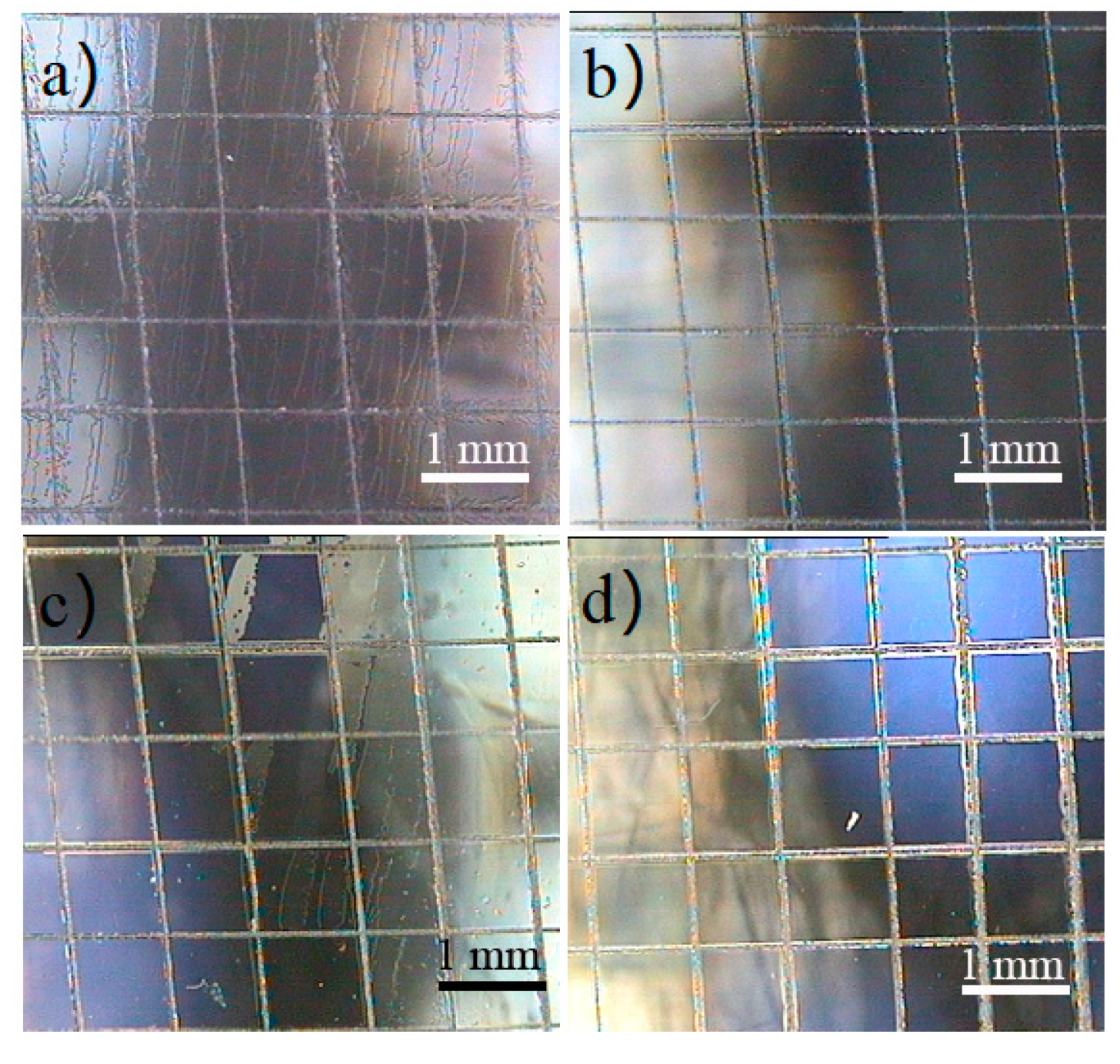
Due to the bent face designed to achieve vision correction effect, adhesion performance as well as thickness of the AR coating deposited via PVD on ophthalmic lens may vary at different positions for each lens. In order to be identical, position A and B locate on convex surface while position C and D locate on concave surface on lens. The following results show a discrepancy of adhesion performance at different positions exists. A microscope magnification image of No. 6 sample is taken as an example shown in Figure 5. From Figure 5, it is visible that coating adhesion performances at position A and C are not as good as those at position B and D.
According to ISO 2409:2013 [27] widely applied in paints and varnishes on plate substrate, coating detachment level can be divided into six classifications mainly based on detachment percent of grid area. The evaluation criterion is listed below (Table 1).
Based on Table 1, detachment area of the No. 6 sample at position A (Figure 5a) is greater than 65% which can be classified into Classification 5. All 25 squares of the grid set at position A occur detached phenomenon. But at position C, only 40–44% of area can be recognized as detachment from AR coating of the lens which can be classified into Classification 4. It is noteworthy that there are 14 squares of the grid set existing detached phenomenon while five squares detach completely from the AR coating of lens. However, the AR coating at position B and D show good adhesion as no detachment appears (Classification 0). The large discrepancy at different positions on the same AR coating of one lens suggests that it is necessary to select four positions to evaluate coating adhesion performance as precise as possible. Thus, four positions named as position A to D are examined on each lens to evaluate adhesion integrally in order to avoid randomness. To evaluate adhesion strictly, the worst classification of four positions is chosen as the final result. Therefore, for the No. 6 sample, the adhesion result can be catalogued into Classification 5.
As an account of this criterion, the results of the remaining lens samples are evaluated by visual inspection and microscope observation, respectively, in the same test environment and shown in Table 2. None of the 16 lenses shows optimal coating adhesion of Classification 0, implying that it is necessary to evaluate adhesion of coatings at the initial stage.
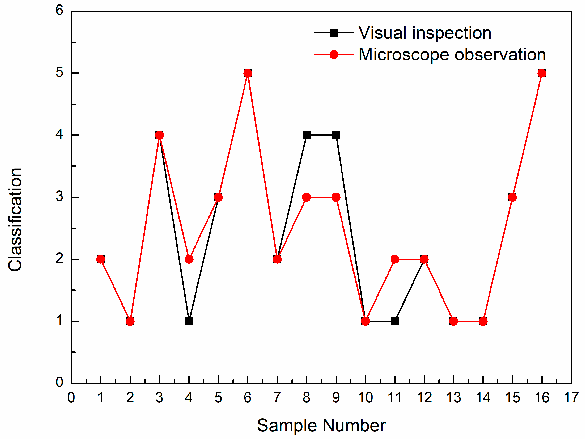
For comparison, the classification results of Table 2 are plotted on a graph shown in Figure 6. It can be seen that classification results are in good agreement by visual inspection and microscopic observation, except for four lenses (No. 4, 8, 9, and 11). A 25% difference exists between visual inspection and microscopic observation. By visual inspection, coating adhesion results for lenses of No. 4 and No. 11 rank at Classification 1, while for lenses of No. 8 and No. 9, the results rank at Classification 2. Since Classification 1 means less detachment of small flakes of the coating, it seems that lenses of No. 4 and No. 11 show better coating adhesion than lenses of No. 8 and No. 9. When magnifying microscope observation is introduced, the classification for lenses of No. 4 and No. 11 is lowered, while the classification for lenses of No. 8 and No. 9 is increased. The reason for opposite results may lie in the substrate nature and magnifying effect. Ophthalmic lenses are transparent substrate, so visually evaluating method is difficult to decide whether the square grids are already destroyed by peeling off or not when flaking is slight. Magnifying microscopic observation can compensate for absence of slight flaking area. Thus, classification belonging to satisfied coating adhesion (like Classification 1) may lower by microscopic observation instead of visual inspection. On the other hand, for coating adhesion that is not that good (like Classification 2), irregular grids are more widespread on lenses. So, the test operator may add the level of partially detached grid subjectively. Magnifying the tiny grids can redress misjudgment, resulting increased classification for lenses of No. 8 and No. 9.
Microscopic observation has the advantage of saving clear and magnifying photographed images. From the point of reproducibility, microscopic observation seems more suitable than visual inspection in evaluating detachment area. Moreover, owing to magnifying photographed images, detachment area can be evaluated more precisely. However, microscopic observation relies on microscopy equipment which is not common or essential in lens manufacture factory. It is impracticable to evaluate adhesion by microscopic observation after AR coating deposited on lens in most of lens manufacture factory. Besides, considering that ISO 2409 method requires comprehensive evaluation of the area ratio of detachment area, evaluation is highly demanding on the test operator’s professional experience and professional level. Result discrepancy among different test operators caused by subjective factor seems in existence. To avoid difficulty of evaluation detachment area, another evaluation criterion on account of counting detachment flakes amount is carried out as following.
In fact, evaluation criterion in Table 3 is from Chinese standard GB 10810.4 [32]. According to specification of currently effective standard GB 10810.4, the results are shown in Table 4. As mentioned above, there are four positions selected to evaluate adhesion, therefore, average detachment amount is introduced as an index to determine whether coating adhesion is qualified or not integrally. The value of “average detachment amount” equals that the sum value of detachment amount at four positions (A–D) is divided by four.
It can be seen that the value of average detachment amount for each lens is close, though the value of sum detachment amount is quite different when judging by visual and microscopic observations, respectively. According to GB 10810.4, the proportion of detachment amount shall be smaller than 15%, in other words, the average detachment amount shall be less than 3.75. When No. 5, 9, and 14 lenses are judged by the two observation means, adverse evaluations of qualified and unqualified occur, as shown in Figure 7. By visual inspection, No. 5, 9, and 14 lenses are qualified. The reason may be that lens sample is transparent and the scratching 100 squares are tiny. It is easy to ignore part of partially detached grids.
Table 5 is the microscope image of the three lenses of No. 5, 9, and 14. It can be seen that if the coating has flaked neatly and partially along the edges, results obtained by visual inspection and microscope observation are in discrepancy. The reason may be that lens sample is transparent and the scratching 100 squares are tiny. It is easy to ignore part of partially detached grids, especially in counting detachment amount.
Microscope observation with magnification effect can make tiny detachment much more apparently than visual inspection which is beneficial to obtain precise result. Although there are many advantages by microscope observation, it is more suitable in an elaborate lab test. It should be recognized that wider application in evaluating AR coating adhesion happens in factories for lens coating where it is scarcely possible to fit microscope equipment. Visual inspection is still an epidemic and effective means. A difference of 18.75% exists between visual inspection and microscopic observation according to counting detachment amount. Regarding lower difference and wider application for detachment amount evaluation (GB 10810.4) than detachment area evaluation (ISO 2409), detachment amount evaluation is recommended. It is worth mentioning that counting detachment amount is easier to operate and less error-prone. In addition, bent lens surface causes deformation of detachment area comparing to plane surface. Evaluation detachment area of tiny scratching grids is also more difficult.
In further work, more lens samples and test labs as well as manufacture factories should be involved in adhesion test for AR coating on ophthalmic lens so that an optimization standardized characterization method can be investigated.
4. Conclusions
In this paper, two evaluation methods (ISO 2409 and GB 10810.4) and two inspection means (visual inspection and microscope observation) for evaluating adhesion of an AR coating on ophthalmic lenses are studied. There is a 25% difference based on evaluation detachment area (ISO 2409) and an 18.75% difference based on counting detachment amount (GB 10810.4) by using visual inspection and microscope observation, implying that counting the detachment amount is more consistent. It is comprehensible that counting the amount is easier and more objective than estimating area. Transparent, bent lens surface, as well as tiny grids, exacerbate difficulty in estimating area. Although microscope images can be recorded to watch repeatedly and be evaluated by different testers to estimate deviation, it is more suitable in a lab testing scene. Visual inspection has the advantage of more application scenarios due to independence of certain equipment. Although visual inspection and microscopic observation results have statistics discrepancy, they are still within acceptable limits.
Author Contributions
Data curation, W.M. and H.H.; investigation, S.Z.; methodology, X.Z. and W.P.; project administration, C.C.; software, L.O.; supervision, J.Y. All authors have read and agreed to the published version of the manuscript.
Funding
This research was funded by the Fundamental Research Funds for the Central Universities; China National Inspection &Testing Centre for Ophthalmic Optic Glass and Enamel Products; the key subject of Shanghai Polytechnic University (Material Science and Engineering), grant number XXKZD1601, EGD19XQD03.
Conflicts of Interest
The authors declare no conflict of interest.
References
- Wu, Q.Y.; Tang, Y.H.; Chen, X.Y.; Ma, C.L.; Yao, F.; Liu, L. Method for evaluating ophthalmic lens based on Eye-Lens-Object optical system. Opt. Express 2019, 27, 37274–37285. [Google Scholar] [CrossRef] [PubMed]
- Wang, L.; Xu, Y.; Chu, Z.; Tang, W.; Qiu, Y.; Zhao, X.; Jiang, W.; Ye, J.; Chen, C. Rapid coating of ultraviolet shielding colloidal crystals. Crystals 2020, 10, 502. [Google Scholar] [CrossRef]
- Flaxman, S.R.; Bourne, R.R.A.; Resnikooff, S.; Ackland, P.; Braithwaite, T.; Cicinelli, M.V.; Das, A.; Jonas, J.B.; Keeffe, J.; Kempen, J.H.; et al. Global causes of blindness and distance vision impairment 1990–2020: A systematic review and meta-analysis. Lancet Glob. Health 2017, 5, 1221–1234. [Google Scholar] [CrossRef] [Green Version]
- Gifford, K.L.; Richdale, K.P.A.; Aller, K.T.; Lam, C.S.; Liu, Y.M.; Michaud, L.; Mulder, J.; Orr, J.B.; Rose, K.A.; Saunders, K.J.; et al. IMI–clinical management guidelines report. Investig. Ophthalmol. Vis. Sci. 2019, 60, 185–203. [Google Scholar] [CrossRef] [PubMed] [Green Version]
- Tadokoro, N.; Jaisupap, K.; Sukbumperng, A.; Pannakarn, S.; Khraikratoke, S.; Jamnongpian, P.; Iwata, N. Investigation of shrinkage and cracking of ophthalmic lens coating by a cycle test of UV radiation and high humidity. Thin Solid Film. 2012, 520, 4169–4173. [Google Scholar] [CrossRef]
- Barbero, S.J. Portilla: Simulating real-world scenes viewed through ophthalmic lenses. J. Opt. Soc. Am. A 2017, 34, 1301–1308. [Google Scholar] [CrossRef] [PubMed] [Green Version]
- Rojo, P.; Royo, S.; Caum, J.; Ramírez, J.; Madariaga, I. Generalized ray tracing method for the calculation of the peripheral refraction induced by an ophthalmic lens. Opt. Eng. 2015, 54, 025106. [Google Scholar] [CrossRef] [Green Version]
- Samson, F. Ophthalmic lens coatings. Surf. Coat. Technol. 1996, 81, 79–86. [Google Scholar] [CrossRef]
- Srivatsa, K.M.K.; Bera, M.; Basu, A.; Bhattacharya, T.K. Antireflection coatings on plastics deposited by plasma polymerization process. Bullet Mater. Sci. 2008, 31, 673–680. [Google Scholar] [CrossRef] [Green Version]
- Bosch, S. Lens coating in thermal evaporation physical vapour deposition chambers: Optimization of the geometrical configuration. J. Phys. D Appl. Phys. 1993, 26, 124–129. [Google Scholar] [CrossRef]
- Pinto, G.; Silva, F.J.G.; Porteiro, J.; Miguez, J.L.; Baptista, A.; Fernandes, L. A critical review on the numerical simulation related to Physical Vapour Deposition. Procedia Manuf. 2018, 17, 860–869. [Google Scholar] [CrossRef]
- Cosar, M.B.; Aydogdu, G.H.; Batman, H.; Ozhan, A.E.S. A solution to adhesion problem of oxide thin films on zinc selenide optical substrates. Surf. Coat. Technol. 2017, 314, 118–124. [Google Scholar] [CrossRef]
- Guo, H.; Wang, Y.G.; Fu, H.R.; Jain, A.; Chen, F.G. Combined negative thermal expansion and anti-reflective effects of ZrW2O8 layer on the VO2 films with an enhanced luminous transmittance. Sol. Energy Mater. Sol. Cells 2020, 211, 110528. [Google Scholar] [CrossRef]
- Grenadyorov, A.S.; Solovyev, A.A.; Oskomov, K.V.; Oskirko, V.O.; Semenov, V.A. Thermal stability of anti-reflective and protective a-C:H:SiOx coating for infrared optics. Appl. Surf. Sci. 2020, 510, 145433. [Google Scholar] [CrossRef]
- Arias, N.; Jaramillo, F. Highly reflective aluminum films on polycarbonate substrates by physical vapor deposition. Appl. Surf. Sci. 2020, 505, 144596. [Google Scholar] [CrossRef]
- Chen, X.; Shaw, C.; Gelman, L.; Grattan, K.T.V. Advances in test and measurement of the interface adhesion and bond strengths in coating-substrate systems, emphasising blister and bulk techniques. Measurement 2019, 139, 387–402. [Google Scholar] [CrossRef]
- Affandi, N.D.N.; Fadil, F.; Misnon, M.I. Preliminary study on the adhesion strength of electrospun bi-layer membranes by 180° peel test. Fibers Polym. 2019, 20, 1317–1322. [Google Scholar] [CrossRef]
- ISO 8980.4:2006. Ophthalmic Optics-Uncut Finished Spectacle Lenses-Part 4: Specifications and Test Methods for Anti-Reflective Coatings; The Inernational Organization for Standardization: Geneva, Switzerland, 2006. [Google Scholar]
- ISO 2819:2017. Metallic Coatings on Metallic Substrates-Electrodeposited and Chemically Deposited Coatings -Review of Methods Available for Testing Adhesion; The Inernational Organization for Standardization: Geneva, Switzerland, 2017. [Google Scholar]
- ISO 4624:2016. Paints and Varnishes-Pull-off Test for Adhesion; The Inernational Organization for Standardization: Geneva, Switzerland, 2016. [Google Scholar]
- ISO 16276-1:2007. Corrosion Protection of Steel Structures by Protective Paint Systems—Assessment of, and Acceptance Criteria for, The Adhesion/Cohesion (Fracture Strength) of a Coating—Part 1: Pull-off Testing; The Inernational Organization for Standardization: Geneva, Switzerland, 2007. [Google Scholar]
- ISO 17132:2007. Paints and Varnishes—T-Bend Test; The Inernational Organization for Standardization: Geneva, Switzerland, 2007. [Google Scholar]
- ISO 22970:2019. Paints and Varnishes-Test Method for Evaluation of Adhesion of Elastic Adhesives on Coatings by Peel Test, Peel Strength Test and Tensile Lap-Shear Strength Test with Additional Stress by Condensation Test or Cataplasm Storage; The Inernational Organization for Standardization: Geneva, Switzerland, 2019. [Google Scholar]
- ISO 8510-1:1990. Adhesives-Peel Test for a Flexible-Bonded to-Rigid Test Specimen Assembly-Part 1: 90° Peel; The Inernational Organization for Standardization: Geneva, Switzerland, 1990. [Google Scholar]
- ISO 8510-2:1990. Adhesives-Peel Test for a Flexible-Bonded to-Rigid Test Specimen Assembly-Part 2: 180° Peel; The Inernational Organization for Standardization: Geneva, Switzerland, 1990. [Google Scholar]
- ISO 16276-2:2007. Corrosion Protection of Steel Structures by Protective Paint Systems—Assessment of, and Acceptance Criteria for, The Adhesion/Cohesion (Fracture Strength) of a Coating—Part 2: Cross-Cut Testing and X-Cut Testing; The Inernational Organization for Standardization: Geneva, Switzerland, 2007. [Google Scholar]
- ISO 2409:2013. Paints and Varnishes—Cross-Cut Test; The Inernational Organization for Standardization: Geneva, Switzerland, 2013. [Google Scholar]
- ISO 20566:2020. Paints And Varnishes-Determination of The Scratch Resistance of a Coating System Using a Laboratory-Scale Car-Wash; The Inernational Organization for Standardization: Geneva, Switzerland, 2020. [Google Scholar]
- ISO 22557:2019. Paints and Varnishes—Scratch Test Using a Spring-Loaded Pen; The Inernational Organization for Standardization: Geneva, Switzerland, 2019. [Google Scholar]
- ISO 18922:2003. Imaging Materials—Processed Photographic Films—Methods for Determining Scratch Resistance; The Inernational Organization for Standardization: Geneva, Switzerland, 2003. [Google Scholar]
- ISO 20502:2005. Fine Ceramics (Advanced Ceramics, Advanced Technical Ceramics)—Determination of Adhesion of Ceramic Coatings by Scratch Testing; The Inernational Organization for Standardization: Geneva, Switzerland, 2005. [Google Scholar]
- GB 10810.4-2012. Uncut Finished Spectacle Lenses—Part 4: Specifications and Test Methods for Anti-Reflective Coatings; The Standardization Administration of the People′s Republic of China: Beijing, China, 2012. [Google Scholar]
Publisher′s Note: MDPI stays neutral with regard to jurisdictional claims in published maps and institutional affiliations. |
Figure 1.
Schematic diagram of 4 positions (grid sets) on one piece of lens.

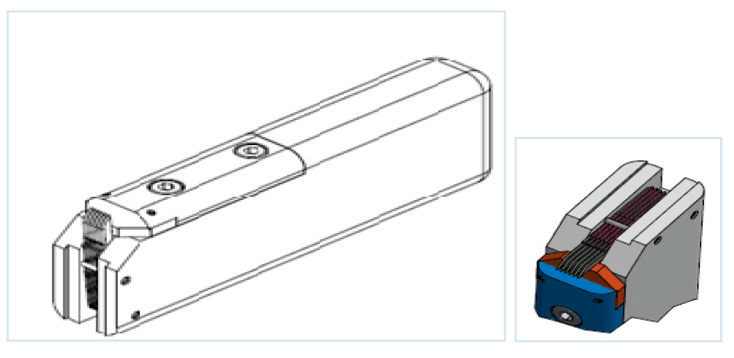
Figure 2.
Schematic diagram of a hand-held cutting tool.

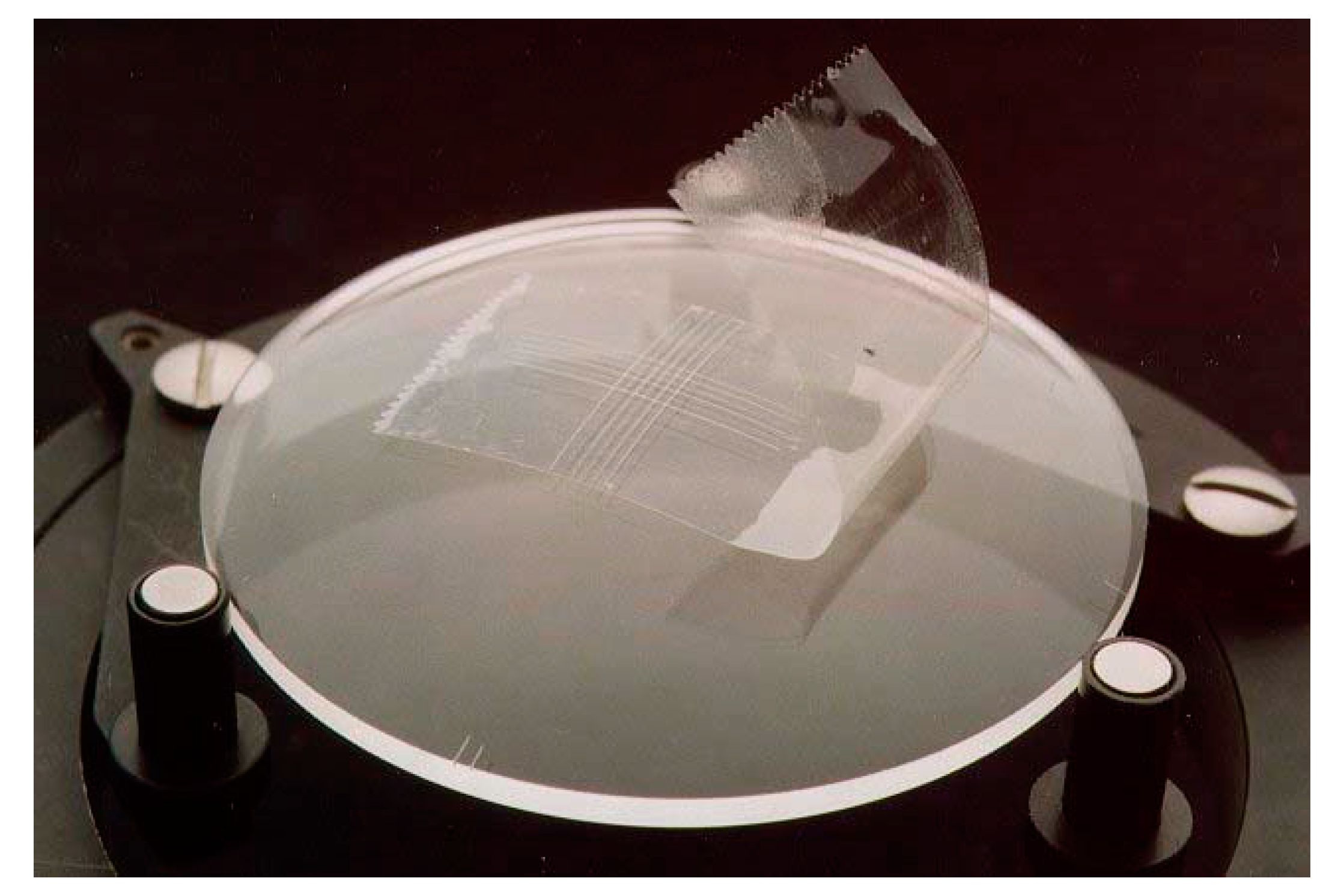
Figure 3.
Schematic diagram of well contact between tape and lens.

Figure 4.
Reflectance spectra of base-lens without AR coatings and lens sample of No. 1–16 with AR coatings. Based on AR coating on No. 1–16 lenses, reflected light intensity decreases compared to the base-lens without AR coatings.
Figure 4.
Reflectance spectra of base-lens without AR coatings and lens sample of No. 1–16 with AR coatings. Based on AR coating on No. 1–16 lenses, reflected light intensity decreases compared to the base-lens without AR coatings.

Figure 5.
Microscope images of scratching squares on No. 6 sample: (a) position A, (b) position B, (c) position C, and (d) position D.
Figure 5.
Microscope images of scratching squares on No. 6 sample: (a) position A, (b) position B, (c) position C, and (d) position D.

Figure 6.
Classification results evaluated by visual inspection and microscope observation, respectively, according to ISO 2409. For No. 4, 8, 9, and 11 samples, different classification is obtained due to different inspection.
Figure 6.
Classification results evaluated by visual inspection and microscope observation, respectively, according to ISO 2409. For No. 4, 8, 9, and 11 samples, different classification is obtained due to different inspection.

Figure 7.
Difference in qualified and unqualified results for No. 5, 9, and 14 sample.


Table 1.
Evaluation criterion according to ISO 2409.
| Classification | Description | Appearance of Grid Sets |
|---|---|---|
| 0 | The edges of the cuts are completely smooth and none of the squares of the lattice is detached. | — |
| 1 | Detachment of small flakes of the coating at the inter-sections of the cuts. A cross-cut area not greater than 5% is affected. |  |
| 2 | The coating has flaked along the edges and/or at intersections of the cuts. A cross-cut area greater than 5%, but not greater than 15%, is affected. |  |
| 3 | The coating has flaked along the edges of the cuts partly or wholly in large ribbons, and/or it has flaked partly or wholly on different parts of the squares. A cross-cut area greater than 15%, but not greater than 35%, is affected. |  |
| 4 | The coating has flaked along the edges of the cuts in large ribbons, and/or some squares have detached partly or wholly. A cross-cut area greater than 35%, but not greater than 65%, is affected. |  |
| 5 | Any degree of flaking that cannot even be classified by classification 4. | — |
Table 2.
Results comparison by visual inspection and microscope observation based on ISO 2409.
| Sample Number | ISO 2409 Method | |
|---|---|---|
| Visual Inspection | 20× Microscope | |
| Classification | Classification | |
| 1 | 2 | 2 |
| 2 | 1 | 1 |
| 3 | 4 | 4 |
| 4 | 1 | 2 |
| 5 | 3 | 3 |
| 6 | 5 | 5 |
| 7 | 2 | 2 |
| 8 | 4 | 3 |
| 9 | 4 | 3 |
| 10 | 1 | 1 |
| 11 | 1 | 2 |
| 12 | 2 | 2 |
| 13 | 1 | 1 |
| 14 | 1 | 1 |
| 15 | 3 | 3 |
| 16 | 5 | 5 |
Table 3.
Evaluation criterion according to GB 10810.4.
| Classification | Description |
|---|---|
| — | The edges of the cuts shall be completely smooth; none of the squares of the lattice shall be detached. If the coating has flaked along the edges and/or at intersections of the cuts, the number of flaking grids shall be smaller than 15%. Completely detachment of coating within one grid is not permitted. |
Table 4.
Results obtained by visual inspection and microscope observation based on GB10810.4 respectively.
Table 4.
Results obtained by visual inspection and microscope observation based on GB10810.4 respectively.
| Lens Number | GB 10810.4 | |||
|---|---|---|---|---|
| Visual Inspection | 20× Microscope Observation | |||
| Detachment Amount | Average Detachment Amount 1 | Detachment Amount | Average Detachment Amount | |
| 1 | 13 | 3 | 13 | 3 |
| 2 | 18 | 5 | 21 | 5 |
| 3 | 31 | 8 | 40 | 10 |
| 4 | 37 | 9 | 41 | 10 |
| 5 | 10 | 3 | 25 | 6 |
| 6 | 39 | 10 | 39 | 10 |
| 7 | 8 | 2 | 9 | 2 |
| 8 | 22 | 6 | 22 | 6 |
| 9 | 12 | 3 | 27 | 7 |
| 10 | 7 | 2 | 13 | 3 |
| 11 | 25 | 6 | 27 | 18 |
| 12 | 35 | 9 | 45 | 11 |
| 13 | 16 | 4 | 28 | 7 |
| 14 | 10 | 3 | 15 | 4 |
| 15 | 25 | 6 | 41 | 10 |
| 16 | 30 | 8 | 35 | 9 |
1 Average detachment amount means the sum detachment amount of 4 grids divided by 4.
Table 5.
Microscope images of No. 5, 9, and 14 lenses.
| SampleNumber | Front Surface | Back Surface | ||
|---|---|---|---|---|
| Position A | Position B | Position C | Position D | |
| 5 |  |  |  |  |
| Visual inspection | detachment amount = 10 | detachment amount = 0 | No detachment | No detachment |
| Microscope observation | detachment amount = 10 | detachment amount = 15 | No detachment | No detachment |
| 9 |  |  |  |  |
| Visual inspection | detachment amount = 12 | detachment amount = 0 | No detachment | No detachment |
| Microscope observation | detachment amount = 20 | detachment amount = 7 | No detachment | No detachment |
| 14 |  |  |  |  |
| Visual inspection | detachment amount = 10 | detachment amount = 0 | No detachment | No detachment |
| Microscope observation | detachment amount = 15 | detachment amount = 0 | No detachment | No detachment |
© 2020 by the authors. Licensee MDPI, Basel, Switzerland. This article is an open access article distributed under the terms and conditions of the Creative Commons Attribution (CC BY) license (http://creativecommons.org/licenses/by/4.0/).
Share and Cite
MDPI and ACS Style
Zhang, X.; Ma, W.; Zhang, S.; Huang, H.; Ouyang, L.; Peng, W.; Ye, J.; Chen, C. A Comparative Study of Adhesion Evaluation Methods on Ophthalmic AR Coating Lens. Coatings 2020, 10, 979. https://doi.org/10.3390/coatings10100979
AMA Style
Zhang X, Ma W, Zhang S, Huang H, Ouyang L, Peng W, Ye J, Chen C. A Comparative Study of Adhesion Evaluation Methods on Ophthalmic AR Coating Lens. Coatings. 2020; 10(10):979. https://doi.org/10.3390/coatings10100979
Chicago/Turabian StyleZhang, Xin, Wei Ma, Songjin Zhang, Hongliang Huang, Liu Ouyang, Wei Peng, Jiayi Ye, and Cheng Chen. 2020. "A Comparative Study of Adhesion Evaluation Methods on Ophthalmic AR Coating Lens" Coatings 10, no. 10: 979. https://doi.org/10.3390/coatings10100979
Note that from the first issue of 2016, this journal uses article numbers instead of page numbers. See further details here.