

Abstract
3D printing is widely used for manufacturing complex non-functional parts, and recently, the fabrication of electronics has also attracted research attention. The commercialized process of fused-filament fabrication (FFF), which is still evolving,has been used in the preparation of basic electronic conductors and sensors but only a few studies of more complex structures with integrated circuits and passive components have been reported. Notably, the usage of FFF in wearable stretchable electronics has not been studied previously. We demonstrate that the combination of FFF printing and commonly used stretchable electronics materials and methods enables new wearable stretchable electronics. In this study, thermoplastics were extruded directly onto a stretchable substrate and their adhesion was measured using T-peel tests. The test results were further used in the fabrication of supports for meander-shaped screen-printed interconnects. The elongation of the interconnects with the supports were studied by tensile tests with simultaneous measurements of the electrical conductivity. The results were good, and the adhesion exceeded the constitution of the substrate when the filament and the substrate were of the same material type. The average bond strength was ∼2 N mm−1. Support structures placed close to the meander-shaped interconnects changed the interconnects' deformation under elongation. The average maximum elongation of the interconnects was improved by ∼27% when the supports directed stresses away from the interconnects' weak areas. Conversely, the results were ∼21% lower when the supports directed stresses towards the weak areas. This study demonstrates that it is possible to use direct 3D printing onto highly stretchable substrates. Currently, commercial FFF materials and methods can be used to manufacture supports, frames and other non-functional parts on wearable electronics substrates in a single process step. We believe that in the future, FFF will become a valuable tool in the manufacture of inexpensive and reliable wearable electronics.
Export citation and abstract BibTeX RIS

Original content from this work may be used under the terms of the Creative Commons Attribution 4.0 license. Any further distribution of this work must maintain attribution to the author(s) and the title of the work, journal citation and DOI.
1. Introduction
In a normal process flow for manufacturing rigid and flexible PCBs, screen printing is used to pattern interconnects and dielectric layers onto a substrate. In addition to normal rigid and flexible substrates, interconnections are now also fabricated on highly stretchable substrates [1]. However, the use of stretchable substrates has introduced new adhesion and stress concentration issues [2]. In particular, the attachment of rigid electronic modules and components to highly stretchable plastic substrates has proved difficult [3]. In addition, the stress concentrations at the interconnections and the electrical contacts between the conductor and the modules cause reliability problems [4].
In this paper, we show how manufacturing methods based on 3D printing can be used to improve the realiability of stretchable electronics. 3D printing allows the easy fabrication of complex module geometries and support structures for interconnects. The available literature describes many approaches for 3D-printed electronics, but no practical application in the domain of wearable stretchable electronics with fused-filament fabrication (FFF) has been presented [5–10].
1.1. 3D-printed electronics
At present, sensors and electrical structures are successfully integrated into pliable polydimethylsiloxane and thermoplastic polyurethane (TPU) systems by the direct ink writing (DIW) method [5, 6]. The structures fabricated in this way have high maximum elongations but the method is not suitable for pliable multilayered elements and the components require an additional heat treatment to solidify the inks and elastic materials.
In addition, stereolithography (SLA) is used in the fabrication of 3D printed electronics. Micro-sized components, such as coils, can be prepared by a modified two-photon SLA method [7]. SLA is also combined with the DIW method to produce multi-chip modules [8]. These methods can produce accurate and rigid 3D printed electronics on rigid substrates, which could be used as modules in stretchable electronics.
Totally new 3D-printing setups have also been prepared for 3D printed stretchable electronics. For example, gallium-based liquid metal is coprinted with flexible silicon material to make elastic conductors and components [9]. Inflatable silicone membranes, which can work as elastic substrates for stretchable electronics, can be printed on an air-permeable mandrel [10]. However, these setups are still at the development stage; working with liquid metal is inconvenient, components are bulky and inert silicon materials can make the assembly of stretchable systems difficult.
1.2. Direct 3D printing
In this paper, we propose a novel direct 3D printing method for attaching polymer-based supports, PCB islands and other similar structures to a stretchable substrate, which utilizes the widely used FFF method and common additive manufacturing materials. In this method, an FFF machine is used to place a molten polymer material directly onto a stretchable substrate. With this method, the supports for interconnects, frames and mountings for rigid PCB islands can be made easily and cost-effectively using existing non-conductive polymers. Also, multimaterial FFF printing, which can be applied for single-step fabrication of PCB islands on a stretchable substrate, has been used to create bendable wearable electronics [11]. This method is straightforward compared to most other current stretchable electronics manufacturing methods, and takes advantage of the versatility of additive manufacturing processes to form complex 3D structures instead of common planar designs [10].
There are several things which we believe this method will accomplish:
- (a)The adhesion between the melted printing material and the stretchable substrate must be strong enough. In the optimal case, the bonding strength would be better than the constitution of the substrate itself.
- (b)The placement of structures on the substrate must be accurate and reliable. For example, damage to screen-printed interconnects must be avoided when placing structures on the substrate.
- (c)This method allows the fabrication of complex geometries to tackle stress concentration issues on the substrate.
As described in this paper, peel tests were used to test the adhesion between the substrate and direct printed materials. The placement of structures by an FFF printer was also tested by printing support structures for shaped stretchable interconnects. Furthermore, different shapes of support structures were prepared to study how they affect the reliability of the interconnects.
1.3. Support structures for stretchable interconnects
There are two common ways to prepare stretchable interconnects on a highly stretchable substrate: screen printing with stretchable conductive ink and using methods from flexible PCB manufacturing to pattern copper foil onto a stretchable substrate. Screen printing with conductive ink enables simple and short interconnects that can have high elongations [12]. The structures and shapes of ink interconnects crack and induce high relative resistance changes due to strain, which prevents their use in sensitive measurement applications such as bioimpedance lead wires. As the whole structure of the interconnect elongates, the shapes of the interconnects can induce stress concentration and irregular deformations, finally decreasing maximum elongations [13].
The other way to make strechable interconnects is to adhere copper film onto a stretchable substrate and etch it to create meander-shaped interconnects [14]. The copper interconnects have a small and stable resistance increase under elongation because the meander opens and twists, and the conductor itself does not elongate. However, copper interconnects do not elongate as much as ink interconnects and their multi-stage preparation process is complicated.
Thanks to the direct 3D-printing method, it is possible to combine the best properties of the ink and copper interconnects and produce supported meander-shaped silver ink interconnects. The support structures are directly and additively manufactured alongside the interconnects and guide deformations for more regular stretchability.
2. Methods
2.1. Materials
In this work, 100 µm-thick TPU film is used as a substrate. Initially, a TPU film (Platilon® U 4201AU by Covestro) was tested and found to be suitable. However, in practice, the temperature of the heated building plate of the 3D printer affected the TPU film and caused softening and swelling of the film. The softening improves the formation of adhesion between the film and the 3D-printed polymer, but the swelling makes the film unevenly wavy and unsuitable for the process. Therefore, a carrier film is needed to keep the TPU film even and stable in the printing process. A TPU film (Platilon® U U073 by Covestro), which has a 100 µm thick TPU film with a carrier film is used as the substrate. Furthermore, the original polyethylene (PE) carrier film is replaced by a thermally stable polyethylene terephthalate film.
The four materials directly 3D printed onto TPU films are presented in table 1, which introduces the 3D-printing filaments used, their compositions and process temperatures (nozzle temperatures).
Table 1. 3D-printed materials and the printing temperatures of the peel samples.
| Trade name and manufacturer | Polymer | Nozzle temperature (°C) |
|---|---|---|
| nGen, colorFabb | copolyester (CPE) | 235 |
| Nylon, Ultimaker BV | polyamide (PA) | 260 |
| TPU95A, Ultimaker BV | TPU | 240 |
| TPU95A, Ultimaker BV | TPU | 260 |
Copolyester (CPE) and polyamide (PA) filaments are common 3D-printing plastics which have good mechanical properties and are used for more demanding applications. Also, TPU95A is a natural choice for the direct printing because it is based on the same polymer as the film. The recommended printing temperature for TPU95A is 240 °C, but 260 °C can also be used for better adhesion.
In addition to the direct 3D printing, meander interconnects are screen printed onto the film by a screen printer (DEK 248) using conductive silver ink (CI-1036 by ECM). For each sample, the screen printer squeezes the ink twice through the screen using 14 kg of pressure. The ink is heat treated in an oven (30 min at 125 °C) following the screen printing to make the ink conductive [1, 13].
2.2. Preparation of samples
All the test samples are direct printed on the TPU film with an FFF printer (Ultimaker 3 by Ultimaker BV). The film is placed on a heated build plate (80 °C), whose temperature straightens the film, adheres the film temporarily to the build plate and assures sufficient bonding between the film and 3D printed polymer. The thickness of the film is taken into account by setting the z offset value to 0.17 mm in the slicer program used (Cura v. 4.0.0. by Ultimaker BV). Moreover, a 0.4 mm nozzle and a 0.15 mm layer thickness is used in the samples' printing.
The T-peel test samples are based on the SFS-EN ISO 11 339 standard. The length of the samples is 210 ± 1 mm and the width is 25 ± 1 mm. The samples consist of two substrates, the film and the directly 3D-printed bar, which together have 160 ± 1 mm of bonded area and 50 ± 1 mm of separated area. The separated area is made by adding Kapton tape to the TPU film before printing. The thickness of the 3D-printed bar is 0.5 mm, which varies slightly because of the different properties of polymers. The bar is 3D printed with 100% infill density with a rectilinear 45° infill pattern.
In addition, support structures for screen-printed interconnects are 3D printed on the film. The length of the samples is 150 ± 1 mm and the width is 40 ± 1 mm. The meander-shaped interconnects are 1 mm wide, 140 mm long (straightened length ∼310 mm) and have a 30° turn between meanders. The 0.3 mm-thick support structures are 3D printed with TPU filament (Ultimaker TPU95A) using a 260 °C nozzle temperature, in order to produce stiff but still pliable supports. The measured initial resistance of the interconnects before the tensile tests is 10.7 ± 1.3 Ω. Various factors, such as the interconnects' thickness and process steps, affect the resistance. In screen printing, the thickness of the interconnects depends on the heat treatment and the roughness of the substrate. A small (±3 µm) thickness variation can be present for smooth substrates such as plastic films [15]. In the tests, the screen-printed interconnects can also be affected by the 3D-printing process and the removal of the carrier film after the 3D printing. For example, an average increase of 3.2% of the resistance was observed after the carrier film was removed in the final preparation step. Figure 1 presents the preparation steps of the tensile test samples.

Figure 1. The three preparation steps of the support structure sample.
Download figure:
Standard image High-resolution imageAltogether four series of meander samples (with six parallel samples) are tested, one unsupported and three supported, as presented in figure 2. The support structures in figures 2(a) and (b) are designed to toughen the meanders' peaks and figure 2(c) to stiffen the unprinted TPU between the meanders. During the interconnects' elongation, stress concentrates on top of the meanders [16], and it is assumed that the support structures close to the meanders' peaks decrease the stress concentration effect and improve the maximum elongation of interconnects.

Figure 2. Direct 3D-printed support structures on the screen-printed TPU film. (a) Curved support inside the meanders. (b) straight support outside the meanders. (c) straight support in the space between the meanders. (d) unsupported meanders.
Download figure:
Standard image High-resolution imageFor comparison, two conventionally shaped straight interconnect samples (2 mm wide and 140 mm long) are also screen printed and tested to see the electrical differences due to the different interconnect shapes. The initial resistance of the straight interconnects is 2.8 Ω.
2.3. Peel tests
In the tests, a tensile test machine with a 500 N force cell is used (Tinius Olsen H5KT). The machine measures the force (N) and the displacement of the upper grip during the tests (mm). The peel test samples are tested using the tensile test machine with 100 mm min−1 speed, 70 mm gauge length and a 1.0 N preload. The displacement limit of the peel tests was 450 mm, which was defined by the height of the tensile test machine. The machine is equipped with 50 mm-wide tacky-film jigs, which prevent the samples from slipping during the tests.
The results of the peel tests provide the bond strength of the samples (N/mm), which was calculated as the measured force divided by the width of the samples. The test series consisted of five parallel samples, and in the comparison, the average maximum bond strength of each test series and the failure mechanisms are analyzed.
2.4. Tensile tests of reinforced printed interconnects
The effect of shaped support structures on the maximum elongation of the interconnects is tested using the tensile test setup, which is presented in figure 3. In the tests, the test speed used was 100 mm min−1, the gauge length was 100 mm and the extension limit was 200 mm. While the tensile test machine measured mechanical properties of the samples, a two-wire measurement system (iCraft ADC 4x by iCraft Oy, Tampere, Finland) measured the electrical properties of the interconnects. The system used a 24-bit A/D channel and measured the voltage across the samples to calculate the resistance of the interconnects. The tensile tests were carried out until the resistance of the samples increased rapidly, which indicated critical failure of the interconnects. The system was calibrated to have less than a ±2% error over the whole measurement range of 0–3000 Ω. The sample was compressed between two PCBs in order to form a stable low-resistance connection.

Figure 3. The tensile test setup. The upper and lower sides of the sample are connected to probes with two PCBs and clamps. The probes are connected to the iCraft measurement system, which measures the electrical behaviour of the sample.
Download figure:
Standard image High-resolution image3. Results
3.1. Peel tests
The results of the T-peel tests are presented in table 2 and figure 4, where the CPE and PA sample series have lower average maximum bond-strength values (under 1 N mm−1) compared to the TPU95A sample series values (between 1.5–2.0 N mm−1). The bond-strength values are complemented by the prevailing failure mechanisms and peeling behaviors of the sample series, which are visualized in figure 5.

Figure 4. Average maximum bond strength (N/mm) and range of the T-peel samples.
Download figure:
Standard image High-resolution image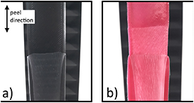
Figure 5. T-peel test samples in the peel tests. (a) PA peel sample that has low adhesion between the TPU film and the direct printed PA bar. The TPU film has pale stripes, which reveal locally higher elongations and adhesion forces in the peeling. (b) TPU95A (260 °C) peel sample before breaking of the film. The film and substrate have distinctly deformed.
Download figure:
Standard image High-resolution imageTable 2. Peel tests' results.
| Sample series | Average maximum bond strength and standard deviation (N mm−1) | Dominant peeling behavior | Dominant failure mechanism |
|---|---|---|---|
| CPE (235 °C) | 0.78 ± 0.08 | Steady | Adhesion failure |
| PA (260 °C) | 0.85 ± 0.05 | Jerky | Adhesion failure |
| TPU95A (240 °C) | 1.70 ± 0.21 | Steady | Adhesion failure |
| TPU95A (260 °C) | 1.88 ± 0.03 | Steady | Substrate failure (of TPU film) |
In the adhesion failure of the peel test samples, the TPU film peels from the direct 3D-printed bar, which is the most typical failure mechanism in the CPE, PA and TPU95A (240 °C) sample series. After the start of peeling, the peeling is steady in the CPE and TPU95A (240 °C) sample series. The PA sample series peels unevenly in jerks, which leaves deformed pale stripes in an otherwise clear TPU film figure 5(a).
The TPU95A (260 °C) sample series has the highest average maximum adhesion with 1.88 N mm−1 of bond strength and an unpredictable failure mechanism. The TPU film is tightly bonded to the 3D-printed bar and at some point in the peeling process, the film breaks instead of continuing to peel. figure 5(b) shows the TPU95A (260 °C) sample before the breaking of the film, when the surface of the 3D-printed bar is ripped and the TPU film is deformed and elongated. The breaking of the film indicates that the strength of the 3D-printed TPU filament is higher than the constitution of the TPU film, thus the bond area of the components is stronger than the TPU film itself.
The TPU film elongates during the peeling, which especially affects the peeling of the more durable TPU95A sample series. To verify the elongation's effect, the beginnings of the peel curves are compared to a tensile test of a bare TPU film, with a gauge length of 35 mm (the length of the TPU film in the peel tests) in figure 6.
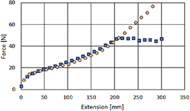
Figure 6. Comparison of a TPU95A peel test (square blue curve) and a tensile test of the TPU film (round orange curve). The curves' points represent every thirtieth measurement point.
Download figure:
Standard image High-resolution imageAs figure 6 shows, the beginning of the peel test of the TPU95A sample series has a gradual increase of force, which resembles the tensile test of the TPU film. In other words, the TPU95A samples have a high enough adhesion to first make the TPU film elongate before the peeling starts.
3.2. Tensile tests
In the tensile test results of the reinforced printed interconnect samples in figure 7, the effects of the different support structures on the interconnects' elongation can be seen. The unsupported meander interconnect samples have, on average, a 35.4% maximum elongation before electrical failure takes place. When bar-shaped supports are added between the meanders (figure 2(c)), the average maximum elongation drops to 29.1%, which is 20.7% lower than the unsupported samples. Correspondingly, the bar supports outside the meanders (figure 2(b)) increase the average maximum elongation to 42.9%, but they also increase the range between the samples. Also, the curved support samples (figure 2(a)) improve the elongation, and the series has an average maximum elongation of 45.3% with a small range. Compared to the unsupported sample series, the bar supports outside the meanders have 26.2% and the curved support samples have 27.3% higher average maximum elongation.
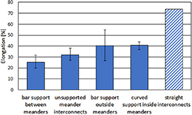
Figure 7. The average maximum elongation (%) and the ranges of the tensile test samples before interconnect failure. As a comparison with the meander interconnects, the patterned column shows the straight interconnects' results.
Download figure:
Standard image High-resolution imagefigure 7 also presents the scale of difference between straight and meander-shaped interconnects. The meander interconnects' average maximum elongation is 35.4%, and the straight interconnects' average elongation is 73.7%. The difference between interconnects can also be seen in figure 8.
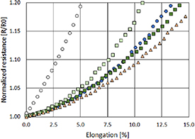
Figure 8. Initial resistance development of tensile test samples. The curves' points present every fifth measurement point. The curves from the largest normalized resistance change to the smallest are: the straight interconnects (light gray circles), bar support between meanders (light green squares), the unsupported meander interconnects (dark blue cirrcles), bar support outside meanders (dark green squares) and curved support inside meanders (light red triangles).
Download figure:
Standard image High-resolution image3.3. Resistance development of interconnects
figure 8 presents the interconnect support samples' initial resistance changes in the tensile tests. The results for the meander-shaped interconnects follow the average maximum elongation results (figure 7). The series with bar supports outside the meander (figure 2(b)) and the curved support (figure 2(a)) sample series have a lower resistance increase than the unsupported samples (figure 2(d)), which indicates a more even elongation of interconnects. The series with bar support between the meanders (figure 2(c)) has a higher resistance increase than the unsupported series, which points to unstable elongation of the shaped interconnects. figure 8 also shows the resistance increase of the straight interconnects, which differs from the meander interconnects. The straight interconnects' resistance increase has a distinctly steeper positive curve than the unsupported meanders', despite the high maximum elongation in figure 7.
It should be noted that the straight interconnects have a distinctly lower initial resistance than the meander-shaped interconnects, which is caused by the larger width and shorter length of the interconnects.
3.4. Interconnects' deformations under elongation
The sample series have different resistance developments under elongation, which are presented in figures 7 and 8. This phenomenon is caused by deformations in the TPU film and the interconnects, which are shown in figures 9 and 10.
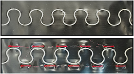
Figure 9. The unstretched unsupported meander interconnect versus the stretched supported interconnect. As the unstretched interconnect is 6 meanders long, the stretched interconnect is 5,5 meanders long. The stretched sample has elongation residues, which are seen from the length of the interconnect and wrinkled film around the 3D-printed supports.
Download figure:
Standard image High-resolution image
Figure 10. The area between two elongated meanders of the interconnect samples. (a) The unsupported meanders have elongated evenly from the tips of the meanders. (b) Bar supports between the meanders induce higher elongations in the meanders' tips. (c) Bar supports outside the meanders have changed the meanders' elongation. Close to the middles of the supports, the interconnects are denser and closer to the supports' edges and the interconnects have cracked more and thus elongated more. (d) Curved supports smooth the elongation of the interconnects and change the shapes of the elongated interconnects a little bit.
Download figure:
Standard image High-resolution image
During the tensile test, the TPU film and the interconnect on it elongates unevenly, due to stiffer support structures. figure 9 presents the unelongated unsupported sample and the elongated supported sample, which differ distinctly. The TPU film of the unsupported sample is smooth, but the elongated support sample has wrinkles around the supports, which are caused by residual strain. The wrinkles indicate that the TPU film and the meander interconnect have elongated less closer to the supports.
As the meanders' elongation is based on the stretching and cracking of the conductive ink, the supports' effect on the interconnect's elongation can be seen as divergent cracking of the conductive ink, which is shown in figure 10. figure 10 presents close-ups from areas between two meanders from all the elongated test series that are shown in figure 2. figure 10(a) shows the unsupported test series, and figure 10(b) presents the sample series with straight supports between the meanders. figure 10(c) shows the straight-support test series with supports just outside the meanders. Finally, figure 10(d) presents the curved-support test series, which had the highest maximum average elongation.
4. Discussion
4.1. Peel tests
Good adhesion between the additively manufactured materials and the stretchable film is a basic requirement for direct 3D-printed stretchable electronic structures. As figures 4, 5 and table 2 present, the TPU95A filament can form a proper bond with the TPU film, which leads to the TPU film's failure before the joint's failure. The filament's adhesion is on the same scale as a laminated copper film's adhesion with the TPU film, which makes the direct 3D-printed structures also usable with laminated- copper interconnects [14].
The bonding of 3D-printed plastic on a plastic film is mainly affected by same factors that influence multi-material FFF printing. In multi-material 3D printing, the material properties, process settings, geometry and environment affect the formation of an interface between two plastics [17]. In particular, diffusion and mechanical interlocking adhesion theories should be applied, which can be improved by increasing the thermal energy radiated and optimizing the surface roughness and geometries of the printing process [17].
In direct 3D printing on a 'semi-manufactured' stretchable substrate, the main method for adhering a 3D printed plastic to a film is based on diffusion theory and the polymer chain mobility at the interface between two polymers. The amount of diffusion is easily controlled in 3D printing by varying the time and temperature of the 3D printing process.
In addition, the first layer of the printed pattern shapes the TPU film, and the pattern can be optimized according to mechanical interlocking theory.
Conventionally solid structures are fabricated on stretchable films using adhesives. The majority of adhesives form a polymeric composition after curing [18]. Different kinds of adhesives have been studied for use in stretchable electronics joints, and the durable bonding of rigid and highly pliant substrates has been found challenging [19]. The removal of the requirement for adhesive is a major benefit of the direct 3D-printing method, which considerably simplifies the fabrication process and improves the stretchability of the system.
4.2. Tensile tests
The tensile tests of supported interconnects showed that directly 3D-printed structures close to screen-printed interconnects can be used to affect the durability of interconnects. Based on the results, the interconnects start to crack from the meanders' tops, and the cracks propagate towards intersections of the meanders. 3D-printed support structures can be used to create stiffened areas on the stretchable film, and they can be placed close to the meanders' tops to make the film's unsupported areas elongate first. The supports can be placed either outside or inside the meanders to stiffen the meanders' top areas. Under elongation, the meanders straighten, which induces tensile stresses in the inside areas and compressive stresses in the outside areas of the meanders. The high stiffness difference between an interconnect material and the stretchable substrate promotes stresses in the meanders, which should particularly be considered in the case of laminated-metal interconnects [20]. Based on the tensile test results, it is more effective to place 3D printed supports inside meanders to prevent tensile stresses in the interconnects.
Overall, the elongations of screen-printed meander-shaped interconnects were lower than assumed, and the unsupported meanders' average maximum elongation was 35.4%. For future work, it would be interesting to prepare curved support structures inside the meanders for optimized meander interconnects with 0° turns [21]. The optimized screen-printed meander interconnects' properties would be somewhere in between the commonly used screen printed unshaped interconnects and laminated-metal-film meander interconnects. The screen printed meander interconnects have a low relative resistance change in figure 8, which makes them a good option for sensing applications, compared to non-shaped screen-printed interconnects or laminated-metal-film interconnects.
It should also noted that the support structures were fabricated with simple planar designs as a proof of concept. Currently, most preparation methods in stretchable electronics use planar designs, which can be replaced with 3D printing. The thicknesses, shapes and locations of direct 3D-printed structures on a stretchable substrate can easily be modified, which makes local control of the elongation of the stretchable substrate possible. As conductive plastics and inks are developed and used, 3D printing can combine several process steps and 3D-printed electronic modules can be made on a stretchable substrate by a single-step method. With recent inventions, such as clover-shaped modules, new customizable and durable wearable electronics can be created [22].
4.3. Interconnects' deformations under elongation
In figure 10, elongated interconnect areas can be seen between two meanders in the four tensile test series. figure 10(a) shows the unsupported meander interconnect, which has a typical elongation mechanism. The interconnect cracks from the tips of the meanders, and the cracks progress evenly towards the transition area of the meanders. The meanders flatten and become thinner when the elongation increases, and finally the cracks in the tips of the meanders break the interconnect. figure 10(b) presents the bar support between the meanders, which decreased the interconnects' elongation. The bar-shaped supports locally decrease the elongation of the TPU film around them, but, on the contrary, the space between the supports has large elongations induced. The supports are placed so that the meanders' tips are just between them, which stretches and straightens the meanders more than in the unsupported sample.
Straight support samples just outside the meanders affected the cracking of the meanders in figure 10(c). The supports blocked elongation in the tips of the meanders, and they have minimum cracking. However, the length of the supports was not enough to protect the whole meander, and they started to crack close to the supports' ends. This local cracking of meanders can cause random failures of interconnects, which explains the high variation of the test series in figure 7.
Curved supports inside the meanders are shown in figure 10(d). The cracking of the meanders is uniform, but the shape of the interconnect has changed a little. As the TPU film elongates more between the supports, the elongation is concentrated in the thicker transition areas of the meanders, which increases the durability of the meanders.
5. Conclusions
In the field of wearables and stretchable electronics, there are various benefits of using an FFF printer to manufacture direct printed structures on a stretchable substrate. This study introduced an easy alternative method for producing deformable supports and frames. Eventually, this work will lead to complex additively manufactured multilayer circuit boards using the multimaterial FFF method. Most importantly, the results demonstrated that the adhesion between 3D-printed TPU material and a stretchable substrate is excellent and can exceed the constitution of the substrate, which is a basic requirement for directly printed supports and other structures. In addition, the direct printing method allows the easy additive manufacture of complex geometries and accurate placement of small shapes without adhesives. Furthermore, the direct printing method is compatible with the most common materials and manufacturing methods used for stretchable electronics. The direct printed structures could be also used as platforms for electronics components.
We demonstrated the approach by direct printing several kinds of support structures for screen-printed stretchable interconnects. With the support structures, the stretchability of the interconnects improved by up to 27.3%. The support structures enable the use of meander-shaped screen-printed interconnects, which have a more stable resistance increase under elongation than traditional straight interconnects; this makes them more suitable for sensing applications, where resistance fluctuations are potential error sources.
We believe that this method will enable cost-effective manufacture for new applications in the fields of smart textiles, wearable healthcare products and automotive interior design. In the future, the authors will continue to develop direct 3D-printing methods for the fabrication of stretchable electronics for wearable applications.
Acknowledgments
This work was funded by the European Union Regional Development Fund (ERDF) and the city of Kankaanpää under the project SOFT3L (Project A73741) and by Business Finland under the project Elastronics (Grant Nos. 2947/31/2018).