Microstructural Evolution and Mechanical Properties of Hybrid Bevel Gears Manufactured by Tailored Forming


 , and
, and
Abstract
:1. Introduction
2. State of the Art
3. Materials and Methods
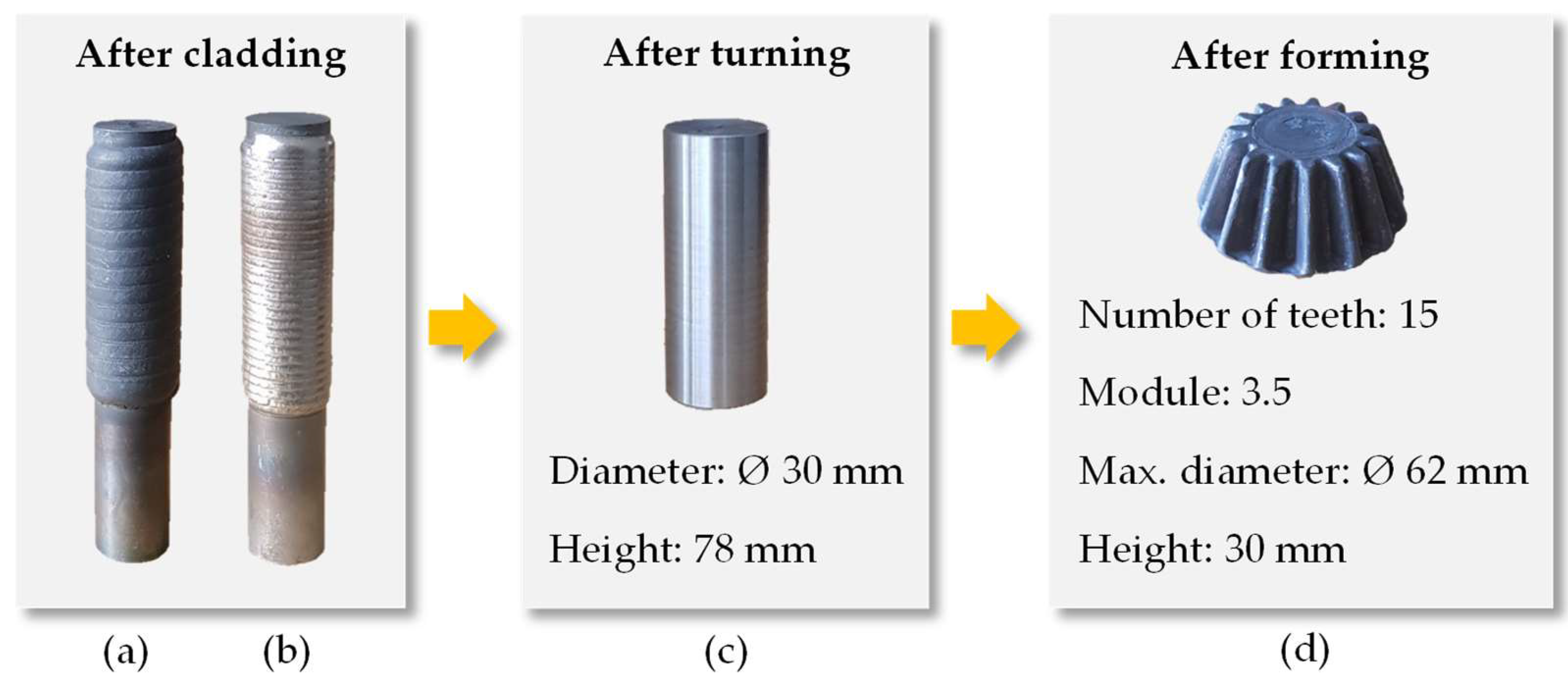
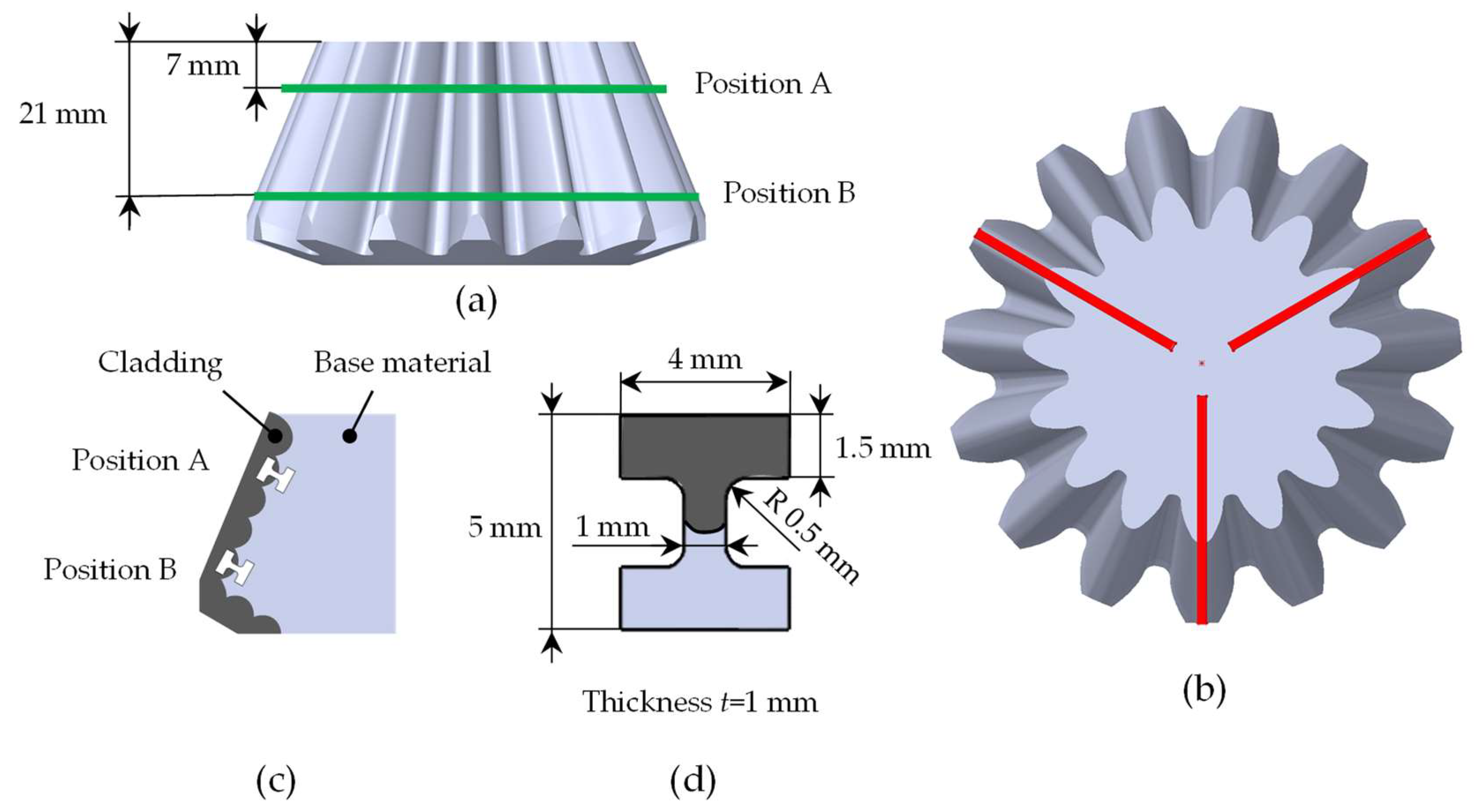
3.1. Initial Geometry
3.2. Die Forging
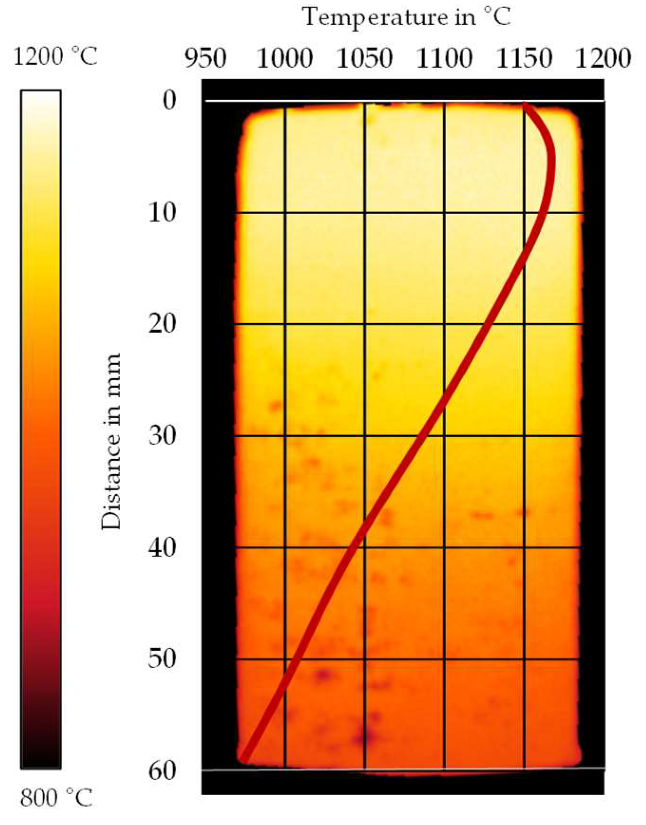
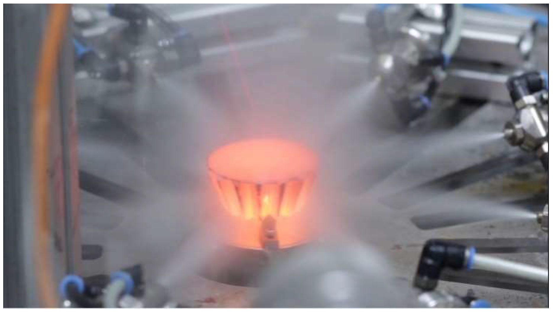
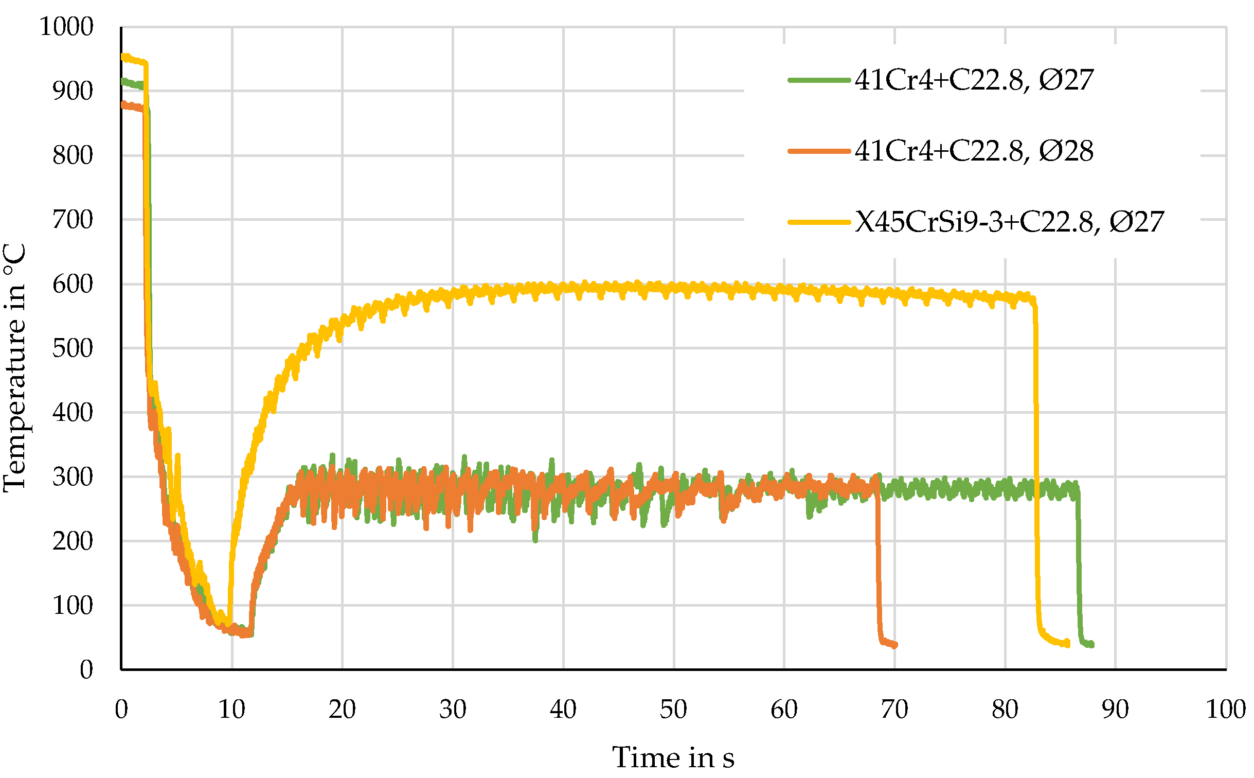
3.3. Heat Treatment
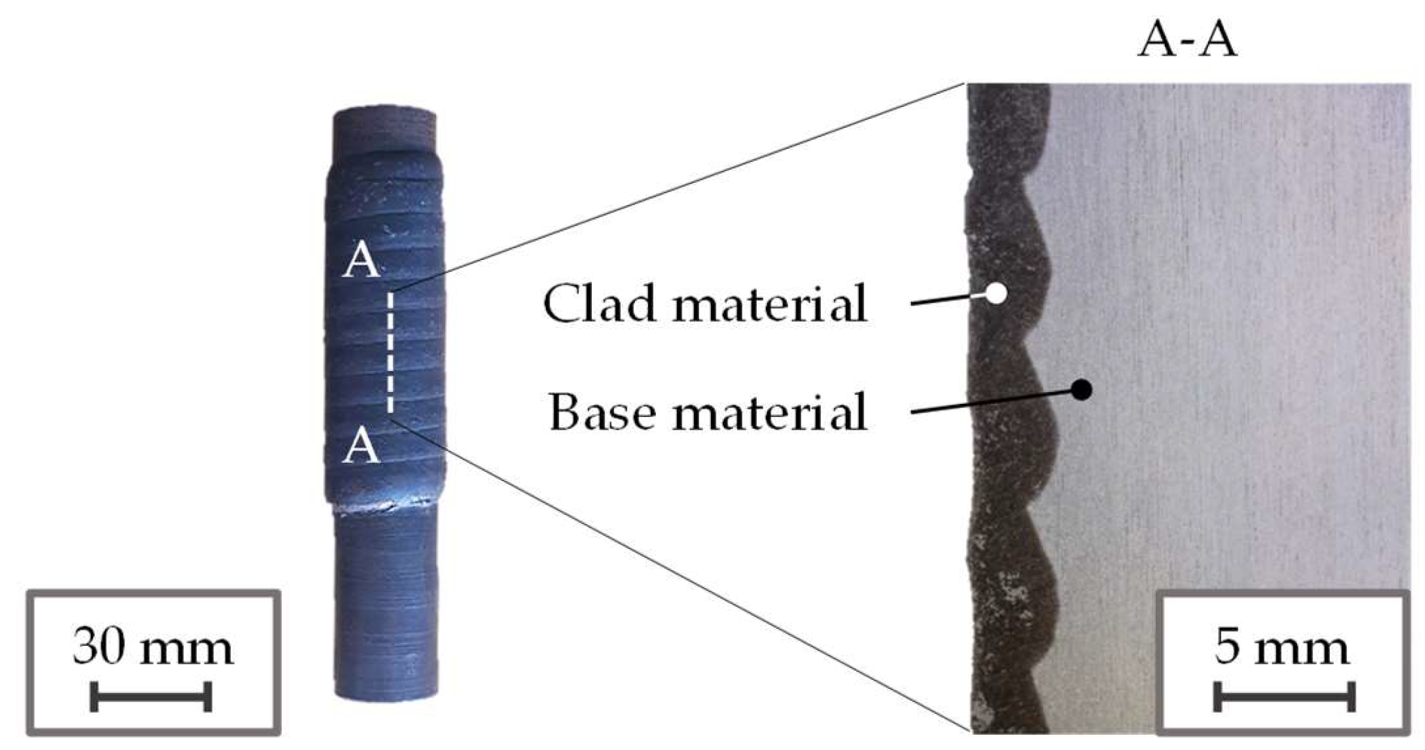
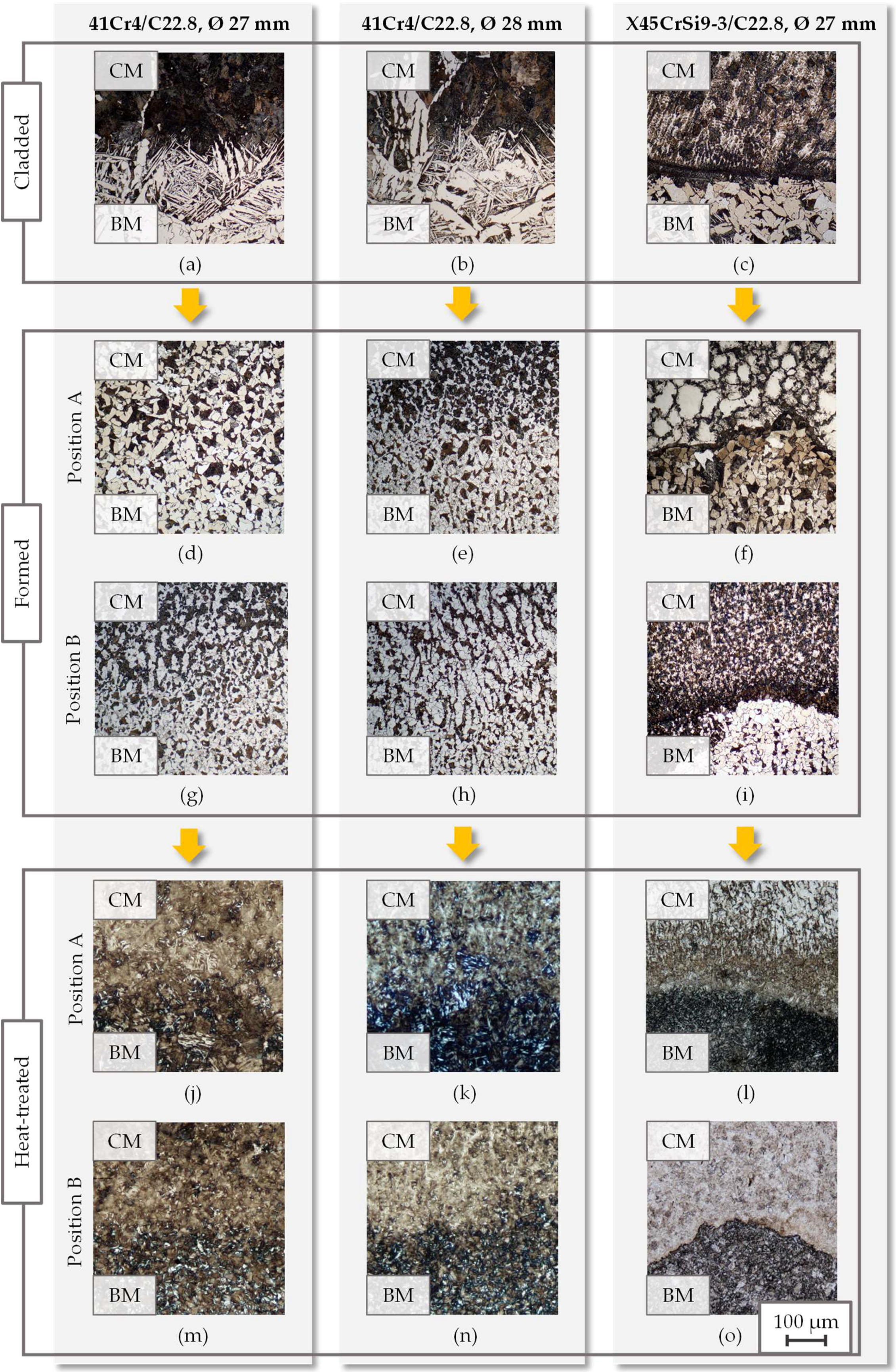
3.4. Investigation of the Joining Zone
4. Results
5. Discussion
6. Conclusions
- The forming process has a great influence on the microstructure refinement. Due to the thermomechanical processing during forging, the initially coarse weld microstructure recrystallizes.
- The cooling strategy has the most important influence on the resulting values of hardness and tensile strength. High cooling rates by air-water spray quenching are the main strengthening factor. In air-cooled condition, hardness and strength remain almost unaffected.
- A process-integrated heat treatment by air-water spray quenching and self-tempering allows tailoring hardness and tensile strength in the cladding and the substrate.
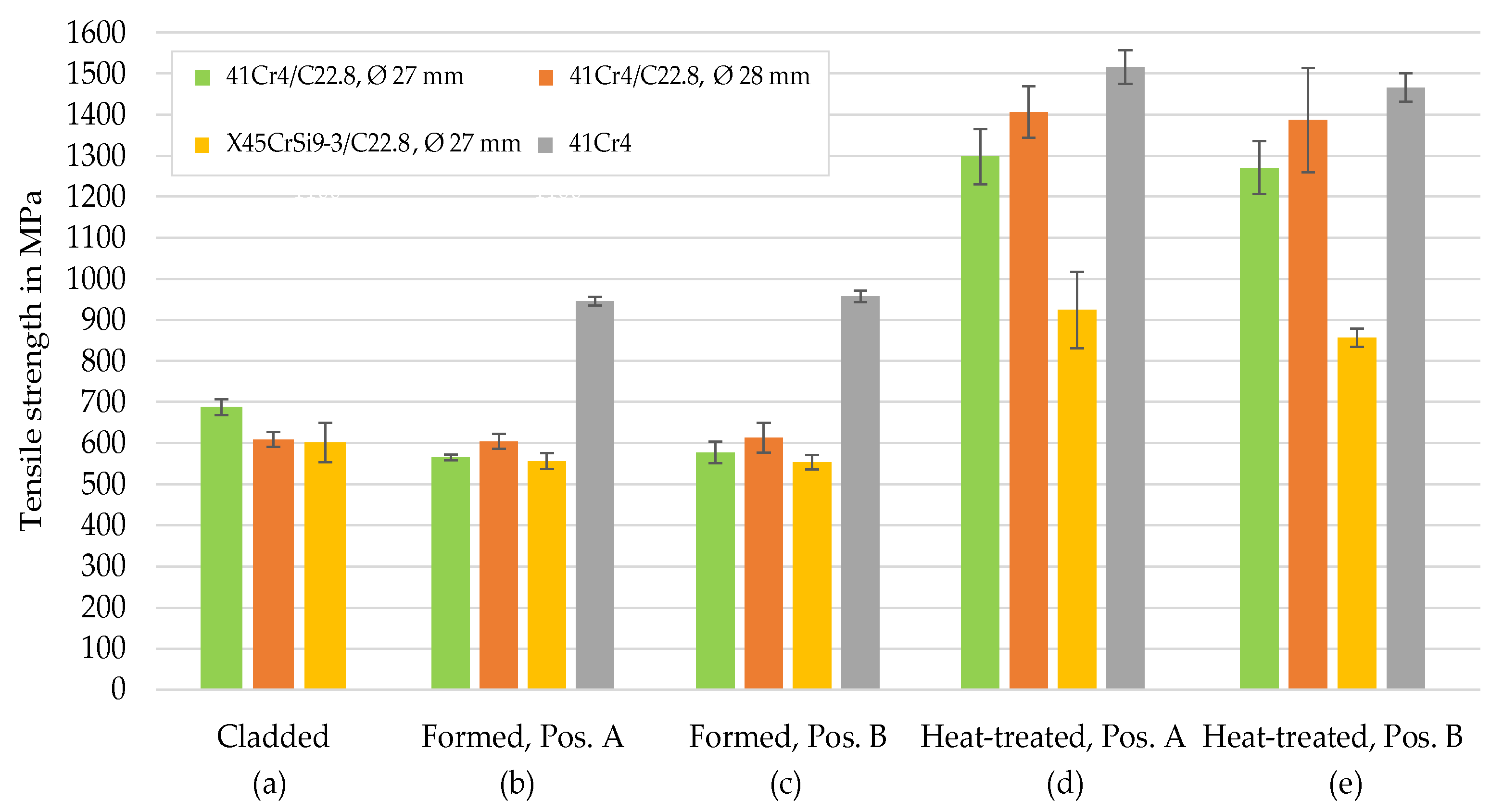
- Since fracture of the hybrid tensile samples occurred in the lower strength substrate, a high quality of the bond at the interface was obtained.
- Hybrid bevel gears of the material combination 41Cr4/C22.8 manufactured by Tailored Forming feature a tensile strength similar to bevel gears of 41Cr4 mono-material.
- In comparison, bevel gears of the material combination X45CrSi9-3/C22.8 show a higher hardness in the cladding layer but a lower hardness in the substrate. While the increased hardness in the cladding is attributed to the formation of chromium carbides, the lower hardness in the substrate is caused by the increased self-tempering temperatures recommended for the steel grade X45CrSi9-3.
- The combination of Tailored Forming and a process-integrated heat treatment allows producing components with adapted hardness gradients by employing different materials and customized time-temperature profiles.
Author Contributions
Funding
Acknowledgments
Conflicts of Interest
References
- Ashby, M.F. Multi-objective optimization in material design and selection. Acta Mater. 2000, 48, 359–369. [Google Scholar] [CrossRef]
- Martinsen, K.; Hu, S.J.; Carlson, B.E. Joining of dissimilar materials. CIRP Ann. 2015, 64, 679–699. [Google Scholar]
- Merklein, M.; Johannes, M.; Lechner, M.; Kuppert, A. A review on tailored blanks—Production, applications and evaluation. J. Mater. Process. Technol. 2014, 214, 151–164. [Google Scholar] [CrossRef]
- Wang, S.; Liu, B.X.; Chen, C.X.; Feng, J.H.; Yin, F.X. Microstructure, mechanical properties and interface bonding mechanism of hot-rolled stainless steel clad plates at different rolling reduction ratios. J. Alloys Compd. 2018, 766, 517–526. [Google Scholar] [CrossRef]
- Carradò, A.; Sokolova, O.; Ziegmann, G.; Palkowski, H. Press joining rolling process for hybrid systems. Key Eng. Mater. 2010, 425, 271–281. [Google Scholar] [CrossRef]
- Behrens, B.-A.; Chugreev, A.; Matthias, T.; Poll, G.; Pape, F.; Coors, T.; Hassel, T.; Maier, H.J.; Mildebrath, M. Manufacturing and evaluation of multi-material axial-bearing washers by tailored forming. Metals 2019, 9, 232. [Google Scholar] [CrossRef] [Green Version]
- Behrens, B.-A.; Sokolinskaja, V.; Chugreeva, A.; Diefenbach, J.; Thürer, S.; Bohr, D. Investigation into the bond strength of the joining zone of compound forged hybrid aluminium-steel bearing bushing. AIP Conf. Proc. 2019, 2113, 040028. [Google Scholar]
- Behrens, B.-A.; Bonhage, M.; Bohr, D.; Duran, D. Simulation Assisted Process Development for Tailored Forming. Mater. Sci. Forum 2019, 949, 101–111. [Google Scholar] [CrossRef] [Green Version]
- Sun, C.Y.; Li, L.; Fu, M.W.; Zhou, Q.J. Element diffusion model of bimetallic hot deformation in metallurgical bonding process. Mater. Des. 2016, 94, 433–443. [Google Scholar] [CrossRef]
- Kong, T.F.; Chan, L.C.; Lee, T.C. Qualitative study of bimetallic joints produced by solid state welding process. Sci. Technol. Weld. Join. 2008, 13, 679–682. [Google Scholar] [CrossRef]
- Wohletz, S.; Groche, P. Temperature influence on bond formation in multi-material joining by forging. Procedia Eng. 2014, 81, 2000–2005. [Google Scholar] [CrossRef] [Green Version]
- Förster, W.; Binotsch, C.; Awiszus, B. Process Chain for the Production of a Bimetal Component from Mg with a Complete Al Cladding. Metals 2018, 8, 97. [Google Scholar] [CrossRef] [Green Version]
- Domblesky, J.; Kraft, F.; Druecke, B.; Sims, B. Welded preforms for forging. J. Mater. Process. Technol. 2006, 171, 141–149. [Google Scholar] [CrossRef]
- Klotz, U.E.; Henderson, M.B.; Wilcock, I.M.; Davies, S.; Janschek, P.; Roth, M.; Gasser, P.; McColvin, G. Manufacture and microstructural characterisation of bimetallic gas turbine discs. Mater. Sci. Technol. 2005, 21, 218–224. [Google Scholar]
- Bach, F.W.; Krause, C.; Behrens, B.-A.; Dahndel, H.; Huskic, A. Integration of heat treatment in precision forging of gear wheels. Arab. J. Sci. Eng. Sect. B Eng. 2005, 30, 103–112. [Google Scholar]
- Puschmann, F.; Specht, E. Transient measurement of heat transfer in metal quenching with atomized sprays. Exp. Therm. Fluid Sci. 2004, 28, 607–615. [Google Scholar] [CrossRef]
- Krause, C.; Wulf, E.; Nürnberger, F.; Bach, F.W. Wärmeübergangs-und Tropfencharakteristik für eine Spraykühlung im Temperaturbereich von 900–100 °C. Forsch. IM Ing. 2008, 72, 163–173. [Google Scholar] [CrossRef]
- Behrens, B.-A.; Bistron, M.; Küper, A. Investigation of load adapted gears and shafts manufactured by compound-forging. J. Adv. Manuf. Syst. 2008, 7, 175–182. [Google Scholar] [CrossRef]
- Behrens, B.-A.; Diefenbach, J.; Chugreeva, A.; Kahra, C.; Herbst, S.; Nürnberger, F. Tailored Forming of Hybrid Bevel Gears with Integrated Heat Treatment. Procedia Manuf. 2020, 47, 301–308. [Google Scholar]
- Rudnev, V.; Loveless, D.; Cook, R.L. Handbook of Induction Heating; CRC Press: London, UK, 2017. [Google Scholar]
- Herbst, S.; Steinke, K.F.; Maier, H.J.; Milenin, A.; Nürnberger, F. Determination of heat transfer coefficients for complex spray cooling arrangements. Int. J. Microstruct. Mater. Prop. 2016, 11, 229–246. [Google Scholar] [CrossRef]
- EN ISO 6507-1: Metallic Materials—Vickers Hardness Test—Part 1: Test Method; International Organization for Standardization: Geneva, Switzerland, 2005.
- EN ISO 6892-1: Metallic Materials—Tensile Testing—Part 1: Method of Test at Room Temperature; International Organization for Standardization: Geneva, Switzerland, 2005.
- Wadleigh, A.S. Multi-Metal Composite Gear/Shaft—Produced by Consecutively Forming, Friction Welding, Reforming and Friction Welding, then Machining Three Elements of Dissimilar Metals. U.S. Patent No. 5492264, 20 February 1996. [Google Scholar]
- Miller, W.H. Gear Blanks. U.S. Patent No. 3847557, 12 November 1974. [Google Scholar]
- Politis, D.J.; Lin, J.; Dean, T.A. Investigation of material flow in forging bi-metal components. Steel Res. Int. 2012, 231, 234. [Google Scholar]
- Politis, D.J.; Lin, J.; Dean, T.A.; Balint, D.S. An investigation into the forging of Bi-metal gears. J. Mater. Process. Technol. 2014, 214, 2248–2260. [Google Scholar] [CrossRef]
- Wu, P.; Wang, B.; Lin, J.; Zuo, B.; Li, Z.; Zhou, J. Investigation on metal flow and forming load of bi-metal gear hot forging process. Int. J. Adv. Manuf. Technol. 2017, 88, 2835–2847. [Google Scholar] [CrossRef]
- Deng, H.X.; Shi, H.J.; Tsuruoka, S.; Yu, H.C.; Zhong, B. Influence of Heat Treatment on Characteristic Behavior of Co-Based Alloy Hardfacing Coatings Deposited by Plasma Transferred Arc Welding. Key Eng. Met. 2011, 462, 593–598. [Google Scholar] [CrossRef]


| Material Combination | 41Cr4, 41Cr4/C22.8, Ø 27 and Ø 28 mm | X45CrSi9-3/C22.8, Ø 27 mm |
|---|---|---|
| Start temperature | 950 °C | 1000 °C |
| Duration 1st phase | 10 s | 8 s |
| Cooling medium 1st phase | Air-water spray | Air-water spray |
| Tempering temperature 2nd phase | 300 °C | 750 °C |
| Cooling medium 2nd phase | Air-water spray | Air-water spray |
| Material Combination | 41Cr4/C22.8, Ø27 mm | 41Cr4/C22.8, Ø28 mm | X45CrSi9-3/C22.8, Ø27 mm | ||
|---|---|---|---|---|---|
| Cladded workpiece | Cladding layer | 299 ± 16 | 289 ± 13 | 379 ± 13 | |
| Substrate | 164 ± 7 | 165 ± 13 | 146 ± 3 | ||
| After forging | Position A | Cladding layer | 221 ± 9 | 262 ± 8 | 462 ± 77 |
| Substrate | 170 ± 3 | 166 ± 4 | 148 ± 4 | ||
| Position B | Cladding layer | 224 ± 7 | 238 ± 3 | 276 ± 4 | |
| Substrate | 156 ± 8 | 152 ± 4 | 140 ± 2 | ||
| After heat treatment | Position A | Cladding layer | 513 ± 7 | 539 ± 9 | 589 ± 23 |
| Substrate | 410 ± 6 | 413 ± 6 | 268 ± 5 | ||
| Position B | Cladding layer | 503 ± 6 | 534 ± 7 | 732 ± 7 | |
| Substrate | 345 ± 12 | 340 ± 14 | 188 ± 3 | ||
© 2020 by the authors. Licensee MDPI, Basel, Switzerland. This article is an open access article distributed under the terms and conditions of the Creative Commons Attribution (CC BY) license (http://creativecommons.org/licenses/by/4.0/).
Share and Cite
Behrens, B.-A.; Chugreeva, A.; Diefenbach, J.; Kahra, C.; Herbst, S.; Nürnberger, F.; Maier, H.J. Microstructural Evolution and Mechanical Properties of Hybrid Bevel Gears Manufactured by Tailored Forming. Metals 2020, 10, 1365. https://doi.org/10.3390/met10101365
Behrens B-A, Chugreeva A, Diefenbach J, Kahra C, Herbst S, Nürnberger F, Maier HJ. Microstructural Evolution and Mechanical Properties of Hybrid Bevel Gears Manufactured by Tailored Forming. Metals. 2020; 10(10):1365. https://doi.org/10.3390/met10101365
Chicago/Turabian StyleBehrens, Bernd-Arno, Anna Chugreeva, Julian Diefenbach, Christoph Kahra, Sebastian Herbst, Florian Nürnberger, and Hans Jürgen Maier. 2020. "Microstructural Evolution and Mechanical Properties of Hybrid Bevel Gears Manufactured by Tailored Forming" Metals 10, no. 10: 1365. https://doi.org/10.3390/met10101365