Article

A Statistical Evaluation of the Influence of Different Material and Process Parameters on the Heat Transfer Coefficient in Gravity Die Casting

Institute of Foundry, RWTH Aachen University, Intzestraße 5, 52072 Aachen, Germany
*
Author to whom correspondence should be addressed.
Metals 2020, 10(10), 1367; https://doi.org/10.3390/met10101367
Submission received: 1 September 2020 / Revised: 29 September 2020 / Accepted: 10 October 2020 / Published: 13 October 2020
(This article belongs to the Special Issue Advances in Metal Casting Technology)

Abstract

:
Local heat transfer in gravity die casting is of great importance for precision in terms of distortion, mechanical properties, and the quality of the castings due to its effect on solidification. Depending on contact conditions such as liquid melt to solid mold, a gap between mold and component, or contact pressure between casting and mold as a result of shrinkage, there are very large differences in heat transfer. The influences of mold material, mold coating and its influence of aging, mold temperature control, and layout on the heat transfer coefficient (HTC) were investigated experimentally for different contact cases. The experiments were carried out on a rotationally symmetrical experimental setup with modular exchangeable die inserts and cores using an AlSi7Mg0.3 alloy. From the results of the individual test series, the quantitative shares of the above-mentioned influencing variables in the respective effective heat transfer coefficients were determined by means of analysis of variance. From this, the parameters having the most significant influence on the local heat balance were derived.

1. Introduction

The heat transfer between casting and mold during gravity die casting has a direct influence on the solidification rate and the corresponding microstructure and, thus, on the mechanical properties of the casting. The formation of casting defects such as shrinkage, distortion, and residual stresses is also a consequence of the heat exchange with the mold. Regarding the heat transfer coefficient (HTC) between casting and mold, two cases can be observed. As long as the melt has not solidified, there is a solid-to-liquid contact between the mold and the casting. This is replaced by a solid-to-solid contact as soon as a solidified, mechanical coherent outer shell forms in the casting. Then, at most areas of the casting–mold interface, a gap forms or contact pressure increases, depending on part geometry.
Investigations on the matter of the heat transfer between mold and casting have a long history [1,2,3,4]. Several of the early works considered heat transfer as a function of the properties (e.g., roughness) of the interacting surfaces [4,5,6]. It was assumed that in the case of an air gap formation this dominates the HTC [2,7,8]. Studies on the formation of air gaps induced by solidification shrinkage during the casting processes has been carried out for a long time as well [1,9]. Later investigations combined these analyses with the HTC determination of the mold–casting interface [2,10,11]. A comparison of different simulation programs and different models for characterizing the dependencies of the HTC showed that gap-dependent descriptions showed the best matches [10]. On the experimental side, the influence of die temperature or cooling rates on the air gap formation was also evaluated [12] as well as the influence on the HTC [7,13]. The relationship between contact pressure and heat transfer was investigated separately, mainly through the application of external forces on the investigated interface [3,14,15]. The initial value of the HTC for the contact condition when the melt is still liquid, thus before the air gap formation or contact pressure building starts, was investigated as well [4,16] as it has a significant influence on the cooling curves.
The respective heat transfer coefficients are influenced by several parameters in permanent mold casting, such as mold temperature, thermal conductivity of the casting and mold, and the thickness and surface roughness of the coating [7,8,17]. The influence of the type and thickness of the coating and the age of the mold coatings on the HTC has been investigated in earlier studies as an isolated parameter [18,19,20]. The first parameter chosen to be investigated in the experimental setup used for this work was the influence of the mold temperature control on the heat transfer [13,21,22]. As in real casting processes, it is obvious that, depending on the geometry of a component, both shrinkage-induced air gap formation and contact pressure can occur in parallel. In the present study, both phenomena were considered simultaneously as in two of the previously mentioned works [21,22].
In the works mentioned above, the authors mainly attempted to describe the HTC using physical models. The complexity of the real casting process, such as movement in the still liquid melt, many disturbance factors and the simultaneously occurring different contact conditions combined with the physical properties of the materials involved, which are not fully known in the solid–liquid range, makes this very difficult. Furthermore, the investigation in each of the mentioned works was limited to researching either individual parameters or small sets of parameters and their influence on the heat transfer between casting and mold, e.g., casting alloy, mold temperature, coating and its thickness in a mold with a practically one-dimensional temperature gradient [7]. Since these investigations were carried out under strongly deviating boundary conditions in very different experimental setups, the significance of the respective influencing parameters on the total HTC can only be derived from them insufficiently. In this work, a different approach is taken. To establish an empirical model describing the HTC based on the physical processes at the melt–mold interface, the active influencing factors in each temperature range must be known. Determining these factors by direct measurement in a macroscale experiment requires the statistical evaluation of the behavior of the HTC compared to that of the relevant material and process parameters. The compilation and combined evaluation of the results obtained in the works on the influence of process and material on the heat transfer coefficient, which were carried out in a single experimental setup under constant boundary conditions [13,20,21,22], allow the determination of their respective share of the total heat transfer coefficient. In addition to the influencing parameters already considered, the layout of the temperature control channels and the mold and core material with different physical properties were added in the current study. In the present case, the analysis of variance (ANOVA) points towards statistical connections and their strength between the HTC and the variables. Thus, a contribution is made to the identification of the relevant influencing parameters for later modeling.

2. Materials and Methods

To avoid geometric influences, the test specimen was designed as a rotationally symmetrical cast part. To provide the possibility of measuring the contact pressure on a core, the cup-shaped test specimen was positioned with the open side facing downwards. In order to ensure a heat flow as radial as possible with simultaneous active cooling, an additional insulation of the bottom and top side was integrated, while temperature control channels for oil temperature control were inserted in the mold inserts arranged around the circumference. The modular design of the mold allowed the use of different mold modules that differed in material or, for example, the layout of the temperature control system. Temperatures were measured via type k thermocouples (TC Mess- & Regeltechnik GmbH, Mönchengladbach, Germany) in the mold modules and in the casting. The measuring setup allowed for an accuracy of ± 2 °C, and all used thermocouples were taken from the same production batch to further reduce the inaccuracies. The thermocouples were placed in groups on the upper side of the mold and the specimen, as well as on the lower side of the core and the specimen to be able to extrapolate the interface temperatures near the measuring points of the gap and the pressure measurements [13,21,22]. For the measurement of gap formation, the displacement of the mold and the casting was measured by means of linear variable differential transformers (LVDTs) (Eddylab GmbH, Otterfing, Germany), which were coupled via quartz glass rods to the mold and the casting. To derive the formation of the gap, the difference in displacement between the mold wall and the casting was determined at three points around the circumference of the component. From these three differences, the gap was then calculated as their mean value. The shrinkage force transmitted from the casting to the core was measured by a load cell (Lorenz Messtechnik GmbH, Alfdorf, Germany) also coupled by a quartz glass rod. The measurements of temperature and air gap formation were carried out in a similar way to previous experiments [23] and described in detail in previous works [13,21,22]. The measurements were recorded with a sampling rate of 20 Hz. Figure 1 shows a sectional view of the experimental setup on the left side, with mold and measuring components, and an exploded view with the changeable die inserts and core marked on the right side.
Figure 2 shows a cast specimen on the left side made during one of the experiments and the mold inserts with the different temperature control channel layouts shown schematically on the right side. The conventionally manufactured inserts with straight cooling channels can be seen in the upper part of the illustration,, and the contour-adapted layout with cooling channels, which are positioned closer to the surface in generative (using selective laser melting) manufactured modules, is shown in the lower part. The entire mold structure is made of X37CrMoV5-1 steel, except for the insulating plates made of calcium silicate, the sand cores, and a set of mold modules made of copper CuCr1Zr.

2.1. Experiments

For the experiments, a common industrially used alloy was chosen, namely A356 (AlSi7Mg0.3), of which the measured composition is given in Table 1. Before each casting, the melt was subjected to a 15 min argon degassing treatment with a flow of 2.5 min−1 and the casting temperature was selected to be 720 °C measured in the crucible directly before pouring. During the tests, the measurements of temperature, displacement, and pressure during solidification and cooling were recorded with a sampling rate of 20 Hz.
In multiple series of experiments in the described setup, different process and material parameters were varied and their influence on the respective heat transfer coefficient between mold or core and casting was determined. The oil temperature control was set to 30, 100, 200, and 300 °C and the effect on the resulting heat transfer was determined [13,21,22] and a corresponding model was derived [22]. The influence of different mold coatings and a plasma-sprayed ceramic permanent coating was considered from the point of view of their individual insulating properties. Moreover, the influence on the HTC, also in terms of coating wear, was determined [20]. The following parameters were then varied in further experiments:
  • Mold inserts made of different materials, once of the standard die steel X37CrMoV5-1 and once made of the copper alloy CuCr1Zr, whereby their geometry was kept the same.
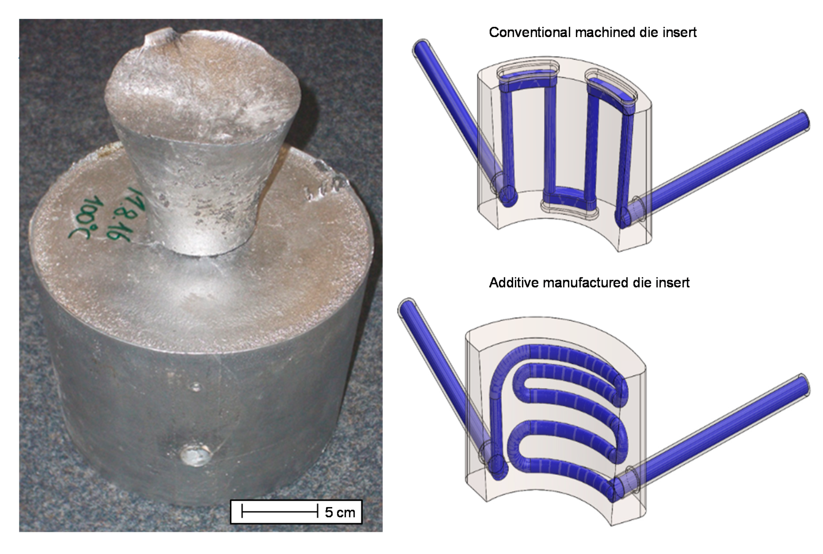
  • Mold inserts once conventionally manufactured with straight temperature control channels at a distance of 15 mm from the cavity and once generatively manufactured with contour-adapted channels at a distance of 10 mm from the cavity (see Figure 2). Both made of the same steel (X37CrMoV5-1).
  • In addition to the steel core, a version made of furan resin sand was also used, which, in addition to significantly different thermal properties, has other contact conditions due to its different surface properties and at least partial compressibility.
  • From the investigation of various mold coatings and their respective wear behavior with regard to the heat transfer [20], to reduce the number of parameters, only a single die coating (KS 81 from Hüttenes-Albertus, Düsseldorf, Germany) was selected for the experiments underlying this work. Furthermore, some experiments were carried out with completely uncoated mold modules. The age of the coating was 2, 3, 4, 5, 6, or 7 previous castings (or set to 20 if no coating was used).

2.2. HTC Determination

When determining the heat transfer coefficient h, three cases must be distinguished depending on the contact conditions. Above the temperature at which a shell has formed, there is liquid–solid contact between melt and mold. This means that there is neither a formed gap ∆x nor a contact pressure p that exceeds the metallostatic one, which can be neglected compared to the magnitude of the contact pressure (i.e., ∆x = 0, p = 0). Accordingly, the application of Equation (1) leads to an incorrect estimate of h with an infinite value when the gap width approaches zero. In fact, under such conditions, there is a high heat transfer coefficient hin. To find a suitable value for the heat transfer coefficient hin, the mean heat flow q = (qc + qm)/2 is calculated according to Equation (2), where qc represents the heat flow from the casting into the gap and qm represents the heat flow from the gap into the mold. Both are calculated from the temperature gradients at the interface determined in the casting and the mold [24].
The other two cases arise as soon as the interface temperature on the melt side falls so far that a coherent shell forms, which can transmit mechanical forces, and thus a firm contact is present. On the outside of the casting towards the mold, gap formation then begins with the width ∆x which increases progressively as the casting shrinks and the mold expands. The heat transfer coefficient at the interface between casting and mold h is determined by the gap width ∆x and the thermal conductivity of air kair according to Equation (1). In that equation, kair is the temperature-dependent thermal conductivity of air calculated from the interface temperatures of casting and mold [11], assuming that the gas in the forming gap is air due to the fact that it is open to the environment. It is further assumed that the heat flow across the air gap per time step is constant because the specific heat capacity of the air and that of the ceramic coating are small. The third case is as well present from the point in time when a first coherent shell between the casting and core has solidified. Then, the casting shrinks onto the core and at the core surface the thin formed solid shell exerts a contact pressure p on the core surface. For the calculation of the heat transfer coefficient under the contact pressure p, an analytical model from Mikić [25] was used, where the thermal conductance is considered for an elastic deformation (Equation (3)). In that equation, ks, E′, and σs are the equivalent thermal conductivity, the modulus of elasticity, and the surface roughness of the contacting solid surfaces at the corresponding interface temperatures, respectively. For the calculation of the respective HTCs, the temperature-dependent material characteristics were taken from the database on which the foundry simulation MAGMASOFT® (version 5.3.1, MAGMA Gießereitechnologie GmbH, Aachen, Germany) is based [26], with the exception of the thermal conductivity of air [27]. Since steel and sand as material for the core differ in many physical properties, the normalized heat capacity for the core cpcw was introduced as follows:
h = k a i r Δ x
h = q / ( T c T m )
h = 1.9 k s σ s ( P E ` ) 0.94

2.3. Analysis of Variance (ANOVA)

To establish connections between various parameters and the HTC, an analysis of variance was carried out. The changes in the means for the individual variables were compared using this method. A similar behavior of a variable and the HTC indicates a higher probability that this variable has a significant influence on the HTC. The statistically identified variables can form the basis for future models used to calculate the HTC under different conditions. Accordingly, the influence of different variables listed in Table 2 on the heat transfer coefficients at the mold and core interface are considered independently of each other.
As the development of the relationship of HTC and influencing parameters with changes in interface temperatures were investigated for each interface temperature considered, a new analysis took place. Whether there was a statistical relationship between a variable and the HTC was evaluated by means of the p-value. If it fell below a value of 0.05, a relationship between the corresponding variable at the considered interface temperature and the HTC was assumed. The strength of the influence exerted by this variable is expressed by means of the impact factor (IF). This is the proportion of the variable-related square sum to the total square sum. Since further discussions focus on the impact factor, parameters with a p-value above 0.05 were assigned an impact factor of zero. In the present work, the implementation of ANOVA in the statistical programming language R was used [28].

3. Results

The different test series showed that the gap formed uniformly over the circumference in nearly all experiments, as expected from the rotationally symmetrical component. Figure 3 shows an example of the measured values of an experiment with copper mold inserts, steel core, and the mold temperature control set to 100 °C. It can be seen that, almost at the beginning of the solidification, the air gap and the contact pressure start to build up. On the left side, the recorded temperatures and the derived interface temperatures at the point of gap measurement are shown together with the measured gap width. On the right side, the corresponding temperatures towards the core are shown together with the measured contact pressure. More detailed results for the individual test series and parameter variations can be found in the corresponding publications [13,20,21,22].
After the series of experiments under different process conditions, some results had to be discarded because the measuring devices failed (e.g., broken quartz glass rods). The statistical relationship between different measured and process variables with the HTC can be determined by means of an analysis of variance (ANOVA) used on the remaining data sets (listed in Table 3). Of particular interest is the development of the relationships with changes in interface temperature. The interface temperatures considered here were 460, 480, 500, 510, 520, 530, and 540 °C. The reasons for choosing the observed interface temperatures are threefold. The upper limit was chosen because the formation of a solidified shell is assumed to have taken place there, while the inner areas of the casting are still liquid. It is also assumed that, above this temperature, the liquid-to-solid contact condition is dominant with influencing parameters not included in the analysis, e.g., roughness of the surfaces [8,17]. Furthermore, the lower temperature limit was set by the greater rate of failure of the pressure sensors below that temperature [21]. The smaller step size between 500 and 540 °C was picked due to the assumption of changes in behavior in this range prior to the analysis.

3.1. HTC at the Mold–Casting Interface

The impact factors for the HTC at the mold–casting interface for the chosen interface temperatures are listed in Table 4 and their development over the interface temperatures is shown in Figure 4. The strength of the statistical relationships, given here by the relevant impact factors, changes during the cooling of the casting. For the interface at the mold wall with temperature at or above 480 °C, the main influencing factor for the HTC is the thermal conductivity of the mold material (km), with a smaller yet still noticeable impact made by the distance of the cooling channels to the mold wall (cc). The set temperature for the cooling channels (tc) also has an impact over the full temperature range, but the impact factor stays below 1% (IF < 0.01). For an interface temperature of 460 °C, the behavior changes completely. The highest impact factor can now be observed for the thermal conductivity of air (kair) with 68.36%, the gap width (wg) has an impact factor of 7.40%, while the influence of the thermal conductivity of the mold material (km) drops to 4.58%. This change can be attributed to the formation of a gap between the outside of the circular specimen and mold due to the shrinking of the cooling casting. It is noticeable that the age of the coating (ac) has no influence at all in the considered temperature interval, since there are no impact factors for p-values below 0.05. Furthermore, the physical properties of the core seem to be almost negligible for the HTC between casting and mold; only the thermal conductivity of the core material (kc) has a very small influence with a maximum of only 0.5% at 460 °C.

3.2. HTC at the Core–Casting Interface

The impact factors for the HTC at the core–casting interface for the chosen interface temperatures are listed in Table 5 and their development over the interface temperatures is shown in Figure 5. It can be seen that, at the interface of core and casting, the HTC and the investigated variables show different statistical connections than those at the interface to the outer mold. Unlike the behavior at the casting–mold interface, almost all observed parameters show a connection, albeit low, to the HTC at the core over the full observed temperature range. Standouts here are the thermal conductivity of the core material (kc), analogue to the behavior of km at the mold interface, which has the highest impact between 540 and 480 °C. However, the gap width at the mold (wg), the heat capacity of the mold material (cpm), and the age of the coating (ac) have a significant influence. Those show increased values over various points of the observed temperature range. A change in behavior again occurs at a temperature of 460 °C. Here the impact of the thermal conductivity of the core diminishes. The parameters with noticeably increased influence here are the age of the coating (ac) and the heat capacity of air (kair).

4. Discussion

The change in magnitude for the impact factor for the mold wall material heat conductivity (km) below 480 °C for both observed cases fits with the expected temperature range [2,8,18] for the formation of a gas (assumed to be air)-filled gap at the outer mold wall. In the higher temperature range showing stable behavior, variations in the impact factor value can mostly be explained by a combination of the limited data available for analysis and the small differences in process and handling during casting inherent in the single-part mold casting process [6]. The same reasons are probably responsible for the occurrence of small impacts for variables outside of the otherwise observable behavior.

Comparison of the Mold-Casting and Core–Casting Interface

An explanation for the differences in behavior at the interfaces for core and mold can be sought in the different cooling conditions, since cooling channels are only present in the outer mold, and in the different contact conditions at the interfaces created by the shrinking of the casting onto the core leading to contact pressure, while creating a gap with the mold wall. Furthermore, the development of the temperature distribution in the core cannot be assumed to be quasi one-dimensional like near the center of the mold wall due to heat transfer from multiple directions into the core simultaneously.
The development of a more complex temperature state is assumed to lead to higher fluctuations in the influence of the various parameters. This leads to the observed changes in the behavior of low impact factors for a high number of influencing variables.
The behavior of the mold and core wall interfaces at 460 °C differs significantly from the behavior at higher temperatures, as previously described. The impact factors for the interface temperature 460 °C for the two contact cases are shown in Figure 6. The significant change in contact condition at or above this temperature, experienced in different ways by the two contact zones, leads to the replacement of thermal conductivity of the wall material (km, kc) with parameters dependent on the contact conditions as the most impactful factors influencing the HTC. For the mold wall, the newly important parameter is the thermal conductivity of air (kair), followed by the nearly unchanged impact of the distance of the cooling channels to the interface (cc) and increasing impact of the gap width (wg). This can be attributed to the formation of a gap between casting and mold wall, replacing the previously active mechanisms for heat flow with the one dominated by the air-filled gap. In contrast to this, the significant impactful parameters at the core-side interface are more widespread, but with a smaller overall impact for the dominating influence, which is the age of the coating (ac). The second highest influence at the core interface is the heat capacity for air (cpair). This is probably due to the formation of a gap at the outer mold wall severely limiting the heat flow in that direction, dependent on the air’s heat capacity. The impact of gap width (wg) and heat capacity of the mold material (cpm) can be considered to affect the heat flows in a similar way. The impact of the age of the coating, on the other hand, is directly connected to the contact condition at the core interface and becomes the most dominating influence. The increasing pressure induced by a shrinking casting leads to a higher influence on the overall heat flow at the interface as influencing parameters such as surface roughness come into account [14]. Since the analysis of variance is based on linear models, a possible attenuation of the effect with more worn coatings cannot be found with this analysis.

5. Conclusions

The results of the current work improve the understanding about the factors influencing the HTC in the permanent mold casting process. They allow for a weighting of these factors dependent on the prevailing contact conditions between mold wall and casting in the investigated temperature range. Differentiated contact conditions include the formation of a gap and the increase in contact pressure during the cooling process.
  • For areas with gap formation, changes of the mold material show the highest impact on the HTC before the gap forms.
  • After the formation of a gap, some influence can be achieved by changing the layout of the cooling channels.
  • Should an increase in contact pressure be observable at the interface, the mold material again shows a strong influence on the HTC at higher temperatures, while at lower temperatures the condition of the coating increases in influence. For this last case, the overall state of the heat flow in the casting also must be considered.
  • The influence of the overall temperature and heat flow distribution may be reducible by facilitating heat transport away from the mold wall using active cooling even under pressure.
For future work, several approaches can be identified. To verify and improve the findings of this work, further experiments are required. This will improve the accuracy of the results, reduce the fluctuations still present, and allow further analysis based on the combined effect of multiple parameters. An expanded data base and more accurate results allow for the formulation of an empirical model for the HTC under a high number of process conditions.

Author Contributions

Conceptualization, N.W. and G.Z.; methodology, N.W. and G.Z.; software, G.Z.; validation, N.W., G.Z., and U.V.; formal analysis, N.W.; investigation, N.W.; resources, N.W.; data curation, G.Z.; writing—original draft preparation, N.W.; writing—review and editing, G.Z. and U.V.; visualization, N.W. and G.Z.; supervision, U.V.; project administration, U.V. and A.B.-P.; funding acquisition, A.B.-P. All authors have read and agreed to the published version of the manuscript.

Funding

This research was funded by the Deutsche Forschungsgemeinschaft e.V. (DFG, German Research Foundation).

Acknowledgments

The presented investigations were carried out at RWTH Aachen University, Aachen, Germany, within the framework of the Collaborative Research Centre SFB1120-236616214 “Bauteilpräzision durch Beherrschung von Schmelze und Erstarrung in Produktionsprozessen” and funded by the Deutsche Forschungsgemeinschaft e.V. (DFG, German Research Foundation). The sponsorship and support is gratefully acknowledged.

Conflicts of Interest

The authors declare no conflict of interest.

References

  1. Engler, S.; Schleiting, G. Spaltbildung beim Gießen von Aluminium-Silicium-Legierungen in Kokille. Gießerei-Forsch. 1978, 30, 25–30. [Google Scholar]
  2. Nishida, Y.; Droste, W.; Engler, S. The Air-Gap Formation Process at the Casting-Mold Interface and the Heat Transfer Mechanism through the Gap. Metall. Trans. B 1986, 17, 833–844. [Google Scholar] [CrossRef]
  3. Sekhar, J.A.; Abbaschian, G.J.; Mehrabian, R. Effect of Pressure on Metal-Die Heat Transfer Coefficient during Solidification. Mater. Sci. Eng. 1979, 40, 105–110. [Google Scholar] [CrossRef]
  4. Ho, K.; Pehlke, R.D. Metal-Mold interfacial heat transfer. Metall. Mater. Trans. B 1985, 16, 585–594. [Google Scholar] [CrossRef]
  5. Griffiths, W.D. The heat-transfer coefficient during the unidirectional solidification of an Al-Si alloy casting. Metall. Mater. Trans. B 1999, 30, 473–482. [Google Scholar] [CrossRef]
  6. Griffiths, W.D. A model of the interfacial heat-transfer coefficient during unidirectional solidification of an aluminum alloy. Metall. Mater. Trans. B 2000, 31, 285–295. [Google Scholar] [CrossRef]
  7. Hallam, C.P.; Griffiths, W.D. A Model of the Interfacial Heat-Transfer Coefficient for the Aluminum Gravity Die-Casting Process. Metall. Mater. Trans. B 2004, 35, 721–733. [Google Scholar] [CrossRef]
  8. Campbell, J. Castings; Butterworth-Heinemann: London, UK, 1991. [Google Scholar]
  9. Lagerstedt, A.; Kron, J.; Yosef, F.; Fredriksson, H. Measurements and modeling of air gap formation in iron-base alloys. Mater. Sci. Eng. A 2005, 413–414, 44–51. [Google Scholar] [CrossRef]
  10. Kron, J.; Bellet, M.; Ludwig, A.; Pustal, B.; Wendt, J.; Fredriksson, H. Comparison of numerical simulation models for predicting temperature in solidification analysis with reference to air gap formation. Int. J. Cast Met. Res. 2004, 17, 295–310. [Google Scholar] [CrossRef] [Green Version]
  11. Ahmadein, M.; Pustal, B.; Wolff, N.; Bührig-Polaczek, A. Determination and Validation of the Gap Dependent Heat Transfer Coefficient during Permanent Mold Casting of A356 Aluminum Alloy. Mater. Sci. Eng. Technol. 2017, 48, 1249–1256. [Google Scholar]
  12. Gunasegaram, D.R.; Nguyen, T.T. Effect of cooling rate on air gap formation in aluminium alloy permanent mould casting. Int. J. Cast Met. Res. 2006, 19, 116–122. [Google Scholar] [CrossRef]
  13. Wolff, N.; Pustal, B.; Vossel, T.; Laschet, G.; Bührig-Polaczek, A. Development of an A356 Die Casting Setup for Determining the Heat Transfer Coefficient Depending on Cooling Conditions, Gap Size, and Contact Pressure. Mater. Sci. Eng. Technol. 2017, 48, 1235–1240. [Google Scholar] [CrossRef]
  14. Griffith, W.D.; Kawai, K. The effect of increased pressure on interfacial heat transfer in the aluminium gravity die casting process. J. Mater. Sci. 2010, 45, 2330–2339. [Google Scholar] [CrossRef]
  15. Fardi Ilkhchy, A.; Jabbari, M.; Davami, P. Effect of pressure on heat transfer coefficient at the metal/mold interface of A356 aluminum alloy. Int. Commun. Heat Mass Transf. 2012, 39, 705–712. [Google Scholar] [CrossRef] [Green Version]
  16. Nayak, R.K.; Sundarraj, S. Sensitivity study of IHTC on solidification simulation for automotive casting. Int. J. Cast Met. Res. 2009, 22, 294–297. [Google Scholar] [CrossRef]
  17. Spinelli, J.E.; Ferreira, I.L.; Garcia, A. Evaluation of heat transfer coefficients during upward and downward transient directional solidification of Al–Si alloys. Struct. Multidiscip. Optim. 2006, 31, 241–248. [Google Scholar] [CrossRef]
  18. Hamasaiid, A.; Dargusch, M.S.; Davidson, C.J.; Tovar, S.; Loulou, T.; Rezaiaria, F.; Dour, G. Effect of Mold Coating Materials and Thickness on Heat Transfer in Permanent Mold Casting of Aluminum Alloys. Metall. Mater. Trans. A 2007, 38, 1303–1316. [Google Scholar] [CrossRef] [Green Version]
  19. Mitterer, C.; Holler, F.; Üstel, F.; Heim, D. Application of hard coatings in aluminum die casting—Soldering, erosion and thermal fatigue behavior. Surf. Coat. Technol. 2000, 125, 233–239. [Google Scholar] [CrossRef]
  20. Wolff, N.; Krampe, J.; Vroomen, U.; Bührig-Polaczek, A. Comparison of the Thermal Properties of Industrially Used Die Coatings and a Plasma Sprayed YSZ Coating for Gravity Die Casting Applications. AFS Trans. 2019, 127, 309–314. [Google Scholar]
  21. Vossel, T.; Wolff, N.; Pustal, B.; Bührig-Polaczek, A. Influence of die temperature control on solidification and the casting process. Int. J. Met. 2019, 1–19. [Google Scholar] [CrossRef]
  22. Wolff, N.; Ahamadein, M.; Pustal, B.; Bührig-Polaczek, A. Identification of relevant Parameters for a gap and pressure dependent heat transfer model for different cooling conditions in gravity die casting. In Proceedings of the Liquid Metal Processing & Casting Conference, Birmingham, UK, 8–11 September 2019; pp. 319–325. [Google Scholar]
  23. Galles, D.; Beckermann, C. Distortion of a Steel Cylinder Casting with a Core. Presented at the 67th SFSA Technical and operating Conference, Chicago, IL, USA, 17 December 2013. [Google Scholar]
  24. Ruifeng, D.; Tianran, G.; Xunliang, L.; Zhi, W. Effects of contact pressure, interface temperature, and surface roughness on thermal contact conductance between stainless steel surfaces under atmosphere condition. Int. J. Heat Mass Transf. 2016, 94, 156–163. [Google Scholar]
  25. Mikić, B.B. Thermal contact conductance; theoretical considerations. Int. J. Heat Mass Transf. 1974, 17, 205–214. [Google Scholar] [CrossRef]
  26. MAGMASOFT®, 5.3. User’s Manual; MAGMA Gießereitechnologie GmbH: Aachen, Germany, 2016. [Google Scholar]
  27. Deutscher Ingenieure, V.; VDI, e.V. VDI-Wärmeatlas. 11; Springer: Berlin/Heidelberg, Germany, 2013; ISBN 978-3-642-19981-3. [Google Scholar]
  28. Core Team, R. R: A Language and Environment for Statistical Computing; R Foundation for Statistical Computing: Vienna, Austria, 2017. [Google Scholar]
Figure 1. A section wise cutaway depiction of the experimental setup with a cast test specimen as well as the attached measuring devices on the left and an exploded view of the setup on the right [13].
Metals 10 01367 g001
Figure 2. On the left is shown a cast test specimen. It has an outer diameter of 153 mm, a height without feeder of 120 mm, a wall thickness of 20 mm, and a 5° draft angle on the inside and outside. The right side shows sketches of the exchangeable die inserts to provide different temperature gradients through different designs of the cooling channels (blue). On the top right is shown the classic design and below is displayed the contour-adapted layout with cooling channels positioned closer to the surface [13].
Metals 10 01367 g002
Figure 3. Measurements of temperatures, gap formation, and contact pressure building for the experiment with copper die inserts, steel core, and the temperature control set to 100 °C [13].
Metals 10 01367 g003
Figure 4. Development of the impact factors for the HTC between casting and mold over the interface temperatures.
Metals 10 01367 g004
Figure 5. Development of the impact factors for the HTC between casting and core over the interface temperatures.
Metals 10 01367 g005
Figure 6. Investigated variables and their impact factors for a casting interface temperature of 460 °C on the left side for the casting–mold interface and, on the right side, for the casting–core interface.
Metals 10 01367 g006
Table 1. Measured chemical composition of the AlSi7Mg0.3 in mass % used in the experiments.
AlSiFeCuMnMgTiOther
Balance7.10.10.020.050.420.09Sr
Table 2. Definition of the parameters investigated for influence on the heat transfer coefficient (HTC).
LabelDescription of Variable
tcTarget temperature in the cooling channels
ccDistance of the cooling channels in the mold from the interface to the casting
kmThermal conductivity of the mold material at the considered interface temperature
cpmHeat capacity of the mold material at the considered interface temperature
wgWidth of the gap between casting and mold wall
kairThermal conductivity of air at the calculated temperature in the gap
cpairHeat capacity of air at the considered interface temperature
acNumber of casts on the coated mold before the test; for tests without coating, a value of 20 casts is used
kcThermal conductivity of the core material at the considered interface temperature
cpcHeat capacity of the core material at the considered interface temperature
cpwcHeat capacity of the core material at the considered interface temperature normalized to the weight of the core
Table 3. Parameter sets used for the statistical analysis.
Parameter SetTemperature Control (°C)Cooling Channel Distance (mm)Mold MaterialCore MaterialAge of Coating
130015coppersteel2
220015coppersteel3
310015coppersteel4
43015coppersteel5
530015coppersand6
63015coppersand7
930015steelsteel2
1330015steelsand6
143015steelsand7
1820010steelsteel3
1910010steelsteel4
2330015coppersteel20
2420015coppersteel20
2510015coppersteel20
263015coppersteel20
2730015coppersteel20
3230015steelsteel2
3320015steelsteel3
3410015steelsteel4
353015steelsteel5
Table 4. Impact factors for the HTC at the casting–mold interface for p < 0.05.
(°C)460480500510520530540
tc0.003978.05 × 10−59.21 × 10−50.006380.004680.002350.00228
cc0.159460.136730.136740.151330.126930.112880.11301
km0.045820.863180.863170.842280.868390.884770.88464
cpm0.019233.49 × 10−7-----
wg0.07403-----1.41 × 10⁻⁵
kair0.68357------
cpair0.00769------
ac-------
kc0.0051-1.14 × 10⁻⁷-1.18 × 10⁻⁷--
cpc-------
cpwc-------
Table 5. Impact factors for the HTC at the casting–core interface for p < 0.05.
(°C)460480500510520530540
tc0.033150.001080.001060.000160.004470.002740.00325
cc0.026370.031790.030250.037460.033950.030520.03078
km0.00060.017440.017560.008170.00131.59 × 10−5-
cpm0.11193-0.120140.096520.108670.120180.07945
wg0.107460.075170.0450.092890.161150.174030.24973
kair0.0030.022830.006440.001070.010140.008520.04854
cpair0.203560.002450.000650.009650.017011.96 × 10−50.03928
ac0.427090.000620.134480.144930.101680.06220.03847
kc0.086770.849930.644260.609030.561540.601630.51035
cpc4.10 × 10−50.00013-----
cpwc1.25 × 10−57.76 × 10⁻⁵---0.00011-

