Up-Concentration of Chromium in Stainless Steel Slag and Ferrochromium Slags by Magnetic and Gravity Separation


Vlaamse Instelling Voor Technologisch Onderzoek (VITO), 2400 Mol, Belgium
*
Author to whom correspondence should be addressed.
Minerals 2020, 10(10), 906; https://doi.org/10.3390/min10100906
Submission received: 31 August 2020
/
Revised: 8 October 2020
/
Accepted: 9 October 2020
/
Published: 12 October 2020
(This article belongs to the Special Issue Ferroalloy Minerals Processing and Technology)
Abstract
:Slags coming from stainless steel (SS) and ferrochromium (FeCr) production generally contain between 1 and 10% Cr, mostly present in entrapped metallic particles (Fe–Cr alloys) and in spinel structures. To recover Cr from these slags, magnetic and gravity separation techniques were tested for up-concentrating Cr in a fraction for further processing. In case of SS slag and low carbon (LC) FeCr slag a wet high intensity magnetic separation can up-concentrate Cr in the SS slag (fraction <150 µm) from 2.3 wt.% to almost 9 wt.% with a yield of 7 wt.%, and in the LC FeCr slag from 3.1 wt.% to 11 wt.% with a yield of 3 wt.%. Different behavior of Cr-containing spinel’s in the two slag types observed during magnetic separation can be explained by the presence or absence of Fe in the lattice of the Cr-containing spinel’s, which affects their magnetic susceptibility. The Cr content of the concentrates is low compared to chromium ores, indicating that additional processing steps are necessary for a recovery process. In the case of high carbon (HC) FeCr slag, a Cr up-concentration by a factor of more than three (from 9 wt.% to 28 wt.%) can be achieved on the as received slag, after a single dry low intensity magnetic separation step, due to the well-liberated Cr-rich compounds present in this slag. After gravity separation of the HC FeCr slag, a fraction with a Cr content close to high grade Cr ores (≥50% Cr2O3) can be obtained. This fraction represents 12 wt.% of the HC FeCr slag, and can probably be used directly in traditional smelting processes.
1. Introduction
In 2018, 50.7 Mt of stainless steel (SS) was produced globally, with an average annual growth of 5.8% since 1950 [1]. It is estimated that approximately 0.3 tons of slag per ton of SS is produced as a by-product [2]; thus, about 17 Mt of SS slag is produced annually. In case of FeCr production, the amount of generated slag depends on the type of produced FeCr. During high-carbon (HC) FeCr production, 1.1–1.6 tons of slag per ton of HC FeCr is produced with a global annual production of 13 Mt HC FeCr in 2018; this implies an annual production of about 17 Mt of HC FeCr slag. In the case of low-carbon (LC) FeCr, the amount of produced slag per ton of LC FeCr is 2.4–2.5 tons with a global annual production 0.9 Mt in 2018 [3], which corresponds to 2.2 Mt of LC FeCr slag.
Although, a significant part of the SS and FeCr slags produced in Europe are being valorized mainly in the construction industry (road construction, addition in cement and concrete, etc.) [4,5], the relatively high Cr content in these slags (1–10 wt.%) [3,6,7] represent a serious obstacle in their full valorization.
In slags from stainless steel and FeCr production, Cr is mostly present in the form of stable spinels, as Cr(III), which is a non-toxic, non-hazardous, essential trace element [8]. However, there is a risk of possible oxidation of Cr(III) to Cr(VI) [9], which present a serious concern for human health and the environment [8].
Moreover, Cr is an element with high economic importance for the EU economy [10] and SS and FeCr slags could be considered secondary raw materials for the recovery of Cr and other valuable elements (e.g., V, Nb, and Mo).
Production of SS and other metal alloys accounts for approximately 85% of Cr consumption [11]. In case of SS production, Cr is added as FeCr, which dependent on carbon content can be classified as high-carbon (HC) FeCr (2–12% C), medium-carbon (MC) FeCr (0.5–4% C), and low-carbon (LC) FeCr (0.01–0.5% C) [12].
HC FeCr is produced mainly by direct carbothermic reduction of chromite ore in submerged arc furnaces (SAF), while MC FeCr can be produced by the silicothermic reduction of chromite ores and concentrates, or by the decarburization of HC FeCr in an oxygen-blow converter. In the European union, LC FeCr is produced by the Duplex process, which is based on silicothermic reduction of a lime-chromite slag in a tiltable AC arc furnace with Søderberg electrodes [12].
Commercial chromite ores used in FeCr production can be classified based on Cr2O3 content as low grade (25–38 wt.% Cr2O3), medium grade (38–50 wt.% Cr2O3), and high grade (>50 wt.% Cr2O3). To use a chromite ore directly as an input for smelting FeCr, the ore generally needs to contain more than 49 wt.% Cr2O3. Chromite ores with Cr2O3 content lower than 49 wt.% need to be further up-concentrated by mineral processing techniques (e.g., magnetic separation, gravity separation, flotation, etc.) [13].
Considering the depletion of high-grade Cr ores and the increasing global demand for SS and FeCr, attention also needs to be paid to recovery of Cr from secondary raw materials. It is evident that, in order to make Cr recovery from SS and FeCr slags by traditional smelting/pyrometallurgical processes economically interesting, the Cr content needs to be increased substantially. This could be achieved by applying mineral processing technologies like magnetic and gravity separation. Several studies dealing with physical separation techniques for up-concentration of Cr from primary Cr ores have been published in the last decade [14,15,16,17].
As the physical and chemical properties of secondary raw materials (e.g., Cr-containing slags) often differ from those of primary Cr-ores, technological solutions used for primary Cr ores need to be adapted for treating these secondary raw materials. For instance, in SS and FeCr slags, small Cr-rich grains (often 10–100 µm) are enclosed in the matrix minerals [3] and to liberate them an additional comminution step needs to be included prior to the separation. By comminution, fine-grained material (often <500 µm) is produced which present a serious challenge for physical separation techniques. This is not the case for primary ores, where grain sizes of 0–15 mm are separated and used in FeCr production [13]. Moreover, Cr in chromite ore is mostly present as Fe-Cr spinel, while the spinels present in SS and LC FeCr slag contain no, or very little, Fe. In the SS and LC FeCr slags the main spinel phase is MgCr2O4 [3].
The main aim of this study was to investigate the potential of magnetic and gravity separation techniques for up-concentration of Cr present in SS and FeCr slags mainly as Cr-containing spinel and Fe–Cr alloy. Up-concentration of Cr by using physical separation could improve both the feasibility of subsequent Cr recovery processes and facilitate the valorization of the Cr-depleted fractions.
2. Materials and Methods
2.1. Materials
SS slag, delivered by slag treatment plant from Belgium and two types of FeCr slags coming from European FeCr producers, were studied. Representative samples of LC FeCr and HC FeCr slags were delivered as size fractions 4–9 mm and 0–6 mm, respectively. The SS slag is an end product after metal recovery and was delivered as a fine powder (D90 = 150 µm).
2.2. Methods
2.2.1. Characterization of the Samples
Representative subsamples were taken from all three slag samples. These subsamples were dried to constant weight at 40 °C. After drying, the samples were crushed, milled, and sieved. Fractions <125 µm were used for chemical and mineralogical analysis.
Chemical analyses of the starting materials were performed by a high performance energy dispersive X-ray fluorescence spectrometer (EDXRF) with polarized X-ray excitation geometry (HE XEPOS, Spectro Analytical Systems, Kleve, Germany). The instrument was equipped with a 50 W tungsten end window tube (maximum 60 kV, 2 mA) and a Silicon Drift Detector. For signal optimization different targets were applied. All analysis was performed under helium atmosphere. Dried and finely ground (<125 μm) samples were analyzed as fused beads. The quantification was performed using a pre-calibrated software package for the quantitative analysis of geological fused beads.
In addition to EDXRF, a handheld XRF analyzer (Niton XL3t GOLDD+, ThermoFisher Scientific, Madison, WI, USA) placed in a mobile test stand, was used for fast elemental analysis of intermediate and final fractions produced by magnetic or gravity separation. The XRF analyzer is equipped with a Ag anode (50 kV and 0.2 mA). Measuring time was 120 s for every measurement. This XRF analyzer was chosen for the analysis based on initial comparison with ICP-OES, EDXRF (powder) and EDXRF (fused bead) where it gave comparable values for Cr and Fe in particular.
Mineralogy was determined by X-ray powder diffraction (XRD), carried out with a PANalytical Empyrean system (PANalytical B.V., Almelo, the Netherlands), operated at 40 kV and 45 mA, with Co tube (fine focus, wavelength = 1.7903 Å). Continuous scans with a step size rate of 0.013°/49.725 s were performed in a 2θ range of 5 to 120° (2D-detector). The obtained diffractograms were qualitatively analyzed with the aid of HighScore Plus software (version 4.6a).
For SEM-EDS analysis, the samples were embedded in a low-viscosity epoxy resin and gradually polished down to ¼ μm diamond powder grit size. The samples were coated with Pt–Pd prior to microscopic analysis. Morphological observations were carried out by a SEM microscope FEI NOVA NANOSEM 450 (Brno, Czech Republic) with EDX analyzer BRUKER QUANTAX 200 (Berlin, Germany) with SDD detector.
2.2.2. Sample Preparation
In cases when crushing and/or milling were applied as pre-treatment methods, a laboratory jaw crusher (Model BB200, Retsch, Germany) and planetary ball mill (Model PM400, Retsch, Germany) were used. Sieving was carried out using a vibratory sieve shaker (Model AS200, Retsch, Germany).
2.2.3. Magnetic Separation
Several magnetic separation techniques were employed in order to up-concentrate Cr-rich phases present in SS and FeCr slags. Based on preliminary experiments, the most suitable magnetic separation techniques were selected for a certain slag. All the magnetic separation equipment was delivered by Master Magnets Ltd. Tested magnetic separation techniques and their allocations to slag materials (including particle size) are listed in Table 1.
LIMS/HIMS (Supplementary Materials, Figure S1a) was carried out by spreading a dry sample of ca. 200 g in a thin layer on a flat surface. The permanent magnet (ferrite or REE(Rare-earth elements) was covered with a plastic bag for convenient removal of the magnetic fraction. After the separation magnetic and non-magnetic fractions were analyzed by XRF.
WLIMS/WHIMS were carried out on a wetchute (Supplementary Materials, Figure S1b) with a permanent magnet (ferrite or REE). A sample of 10 g was mixed with 500 mL water (L:S ratio = 50), and the suspension was fed at the top of the wetchute. The magnetic fraction stayed on the wetchute, while the non-magnetic fraction was washed out. Additional washing of the magnetic fraction with 500 mL of distilled water was carried out to clean the magnetic fraction. Resulting fractions were dried for 24 h at 40 °C before milling (<125 µm) and XRF analysis.
WHIMSe experiments were carried out using WHIMSe separator (Supplementary Materials, Figure S1c). Steel wool was used as a separation matrix. The purpose of the steel wool in the WHIMSe is to hold magnetic (ferro- and paramagnetic) materials in the magnetic field while diamagnetic (non-magnetic) particles are being washed out. The magnetic field in WHIMSe can be adjusted from 0 to 2 T by adjusting the electric current (0–17.5 A) in the coils. As it is difficult to measure the exact magnetic field strength when steel wool is used as a matrix, in this paper the WHIMSe set-up is reported in Amperes. An indicative relation between the electric current (in Amperes) and the magnetic field (in Gauss), provided by the equipment manufacturer, can be found in Supplementary information (Supplementary Materials, Figure S2). The material was first fed into the WHIMSe at the maximum current of 17.5 A and the non-magnetic fraction was washed out. The magnetic fraction was recovered by turning off the magnetic field and washing with water. All output fractions were dried for 24 h at 40 °C before XRF analysis.
In order to optimize WHIMSe for Cr up-concentration, sequential experiments were carried out by gradually decreasing the electric current. In this case, after washing out the non-magnetic fraction at the highest current (17.5 A), the current was sequentially reduced to 15, 10, 5, 1, and 0 A, and the non-magnetic fraction was washed out at every step. The final fractions were dried for 24 h at 40 °C and analyzed by XRF.
2.2.4. Gravity Separation
The gravity separation test was carried out using a Holman–Wilfley wet shaking table (WST). The test was performed only for HC FeCr slag, fraction 1–2 mm. Approximately 360 g of the sample was used for the test. Conditions used during WST separation are listed in Table 2.
The final output fractions were dried for 24 h at 40 °C, milled (<125 µm) and analyzed by XRF. The WST, with the indication of outputs for different fractions (fraction 1 = the lightest; fraction 5 = the heaviest), are shown in Supplementary Materials, Figure S3.
3. Results
3.1. Characterization of the Samples
Table 3 shows the chemical composition of the studied slags analyzed by EDXRF.
The main phases identified in the SS slag by XRD analysis were: Ca-(Mg-Al-)silicates (merwinite, bredigite, akermanite, cuspidine, and dicalcium silicate), calcite, periclase, and spinel (MgCr2O4). Significant differences in chemical composition (Table 3) and mineralogy between LC FeCr slag and HC FeCr slag were observed. In the case of LC FeCr production, reduction with silicon proceeds in the presence of lime, which results in a significantly higher CaO content of the LC FeCr slag (present mainly as bredigite and merwinite minerals in the slag). In the case of HC FeCr slag, also metallic Fe-Cr grains were identified. The reason for the presence of Fe-Cr particles might be that in HC FeCr production, after carbothermal reduction in SAF, molten metal and slag are tapped off through the same tap holes using cascade tapping into the same metal vessel [12].
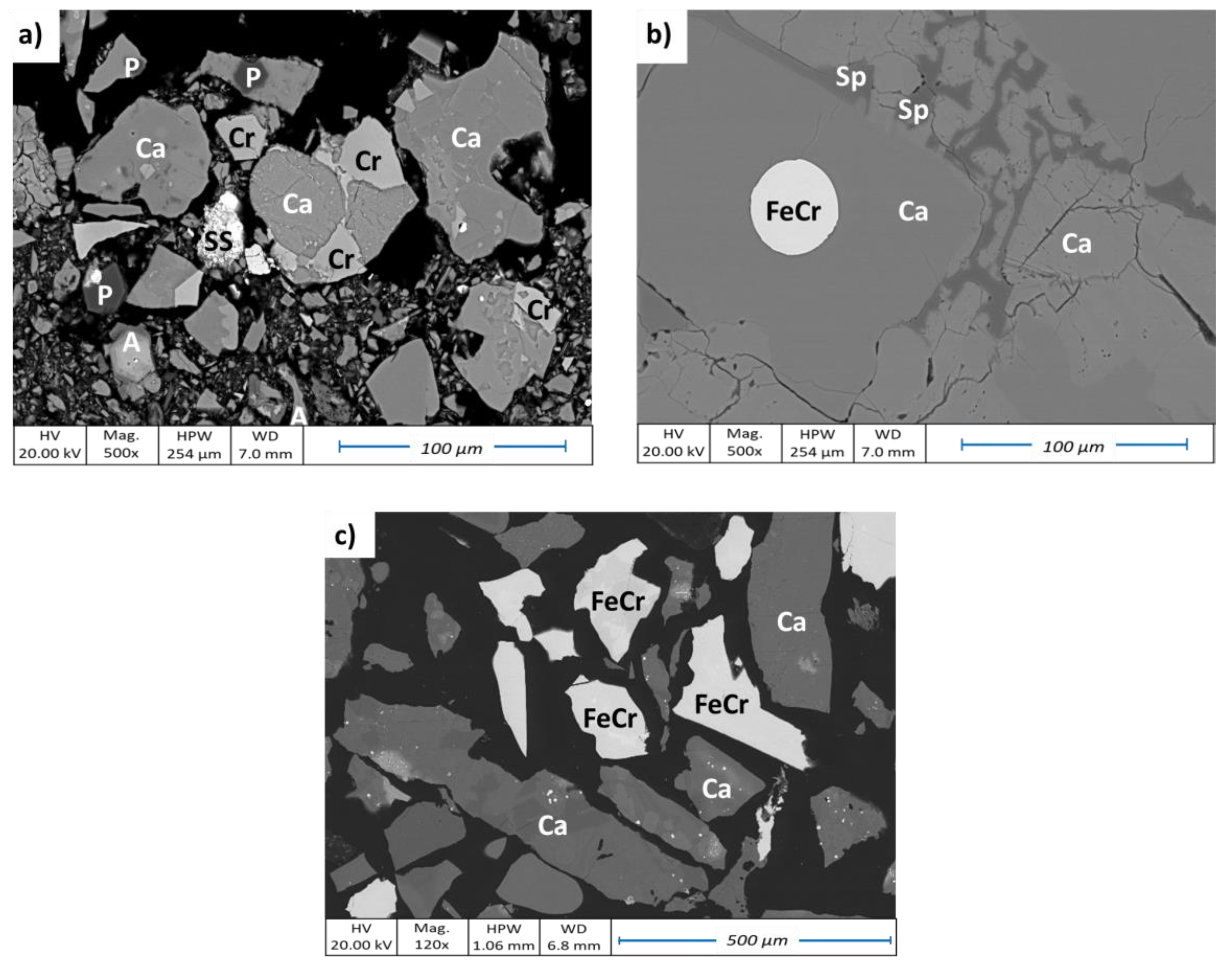
As can be seen from SEM-EDS analysis, the matrix of the SS slag consists of Ca-silicates and Ca-Mg-Al-silicates (Figure 1a). Cr-spinel phases can be clearly identified, showing a potential for physical separation. However, due to the small dimensions of the Cr-rich particles, full liberation would require additional milling.
The SEM-EDS analysis of LC FeCr slag (Figure 1b) shows elongate grains of Ca-silicates in between which veins of spinels are present. Small (20–40 µm) metallic FeCr particles are spread out diffusely over the material. As shown in Figure 1b, some of them are encapsulated in the Ca-silicate matrix. In the case of HC FeCr slag (Figure 1c), Cr-rich grains (mostly as FeCr particles) and Ca-silicates grains are already very well liberated indicating potential for their separation. Observation of the SEM analysis are well aligned with the results of mineral liberation analysis (MLA) published in our recent study [3].
3.2. Results of Magnetic Separation
3.2.1. Magnetic Separation—SS Slag
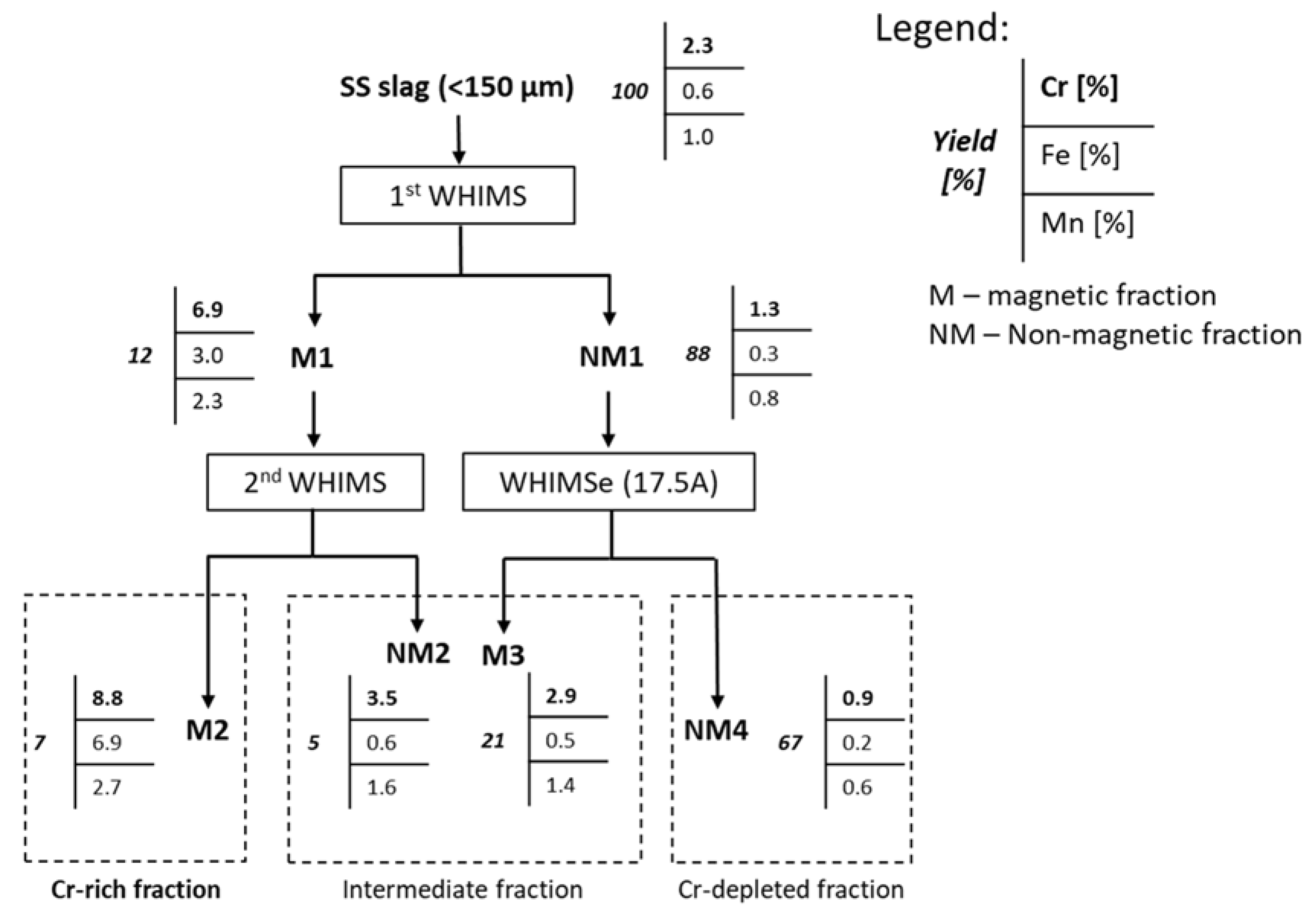
A combination of WHIMS and WHIMSe was used to process SS slag. The final flowsheet, including chemical compositions of input, intermediate and final fractions, is shown in Figure 2. The SS slag, as received (D90 = 150 μm), was treated by WHIMS, after which the magnetic fraction was further purified by a second WHIMS separation step and the non-magnetic fraction was processed by a single WHIMSe separation step (at 17.5 A). Three output fractions (M2, NM2+M3, and NM4) with different Cr contents were obtained. The Cr-rich fraction (M2) contains 8.8% Cr, which represents an increase by almost a factor 4. The weight yield of the Cr-rich fraction was 7% representing 31% of Cr recovery. As expected, Fe was up-concentrated in the M2 fraction together with Cr. Up-concentration of Mn in the same fraction indicates presence of Mn-Cr spinels.
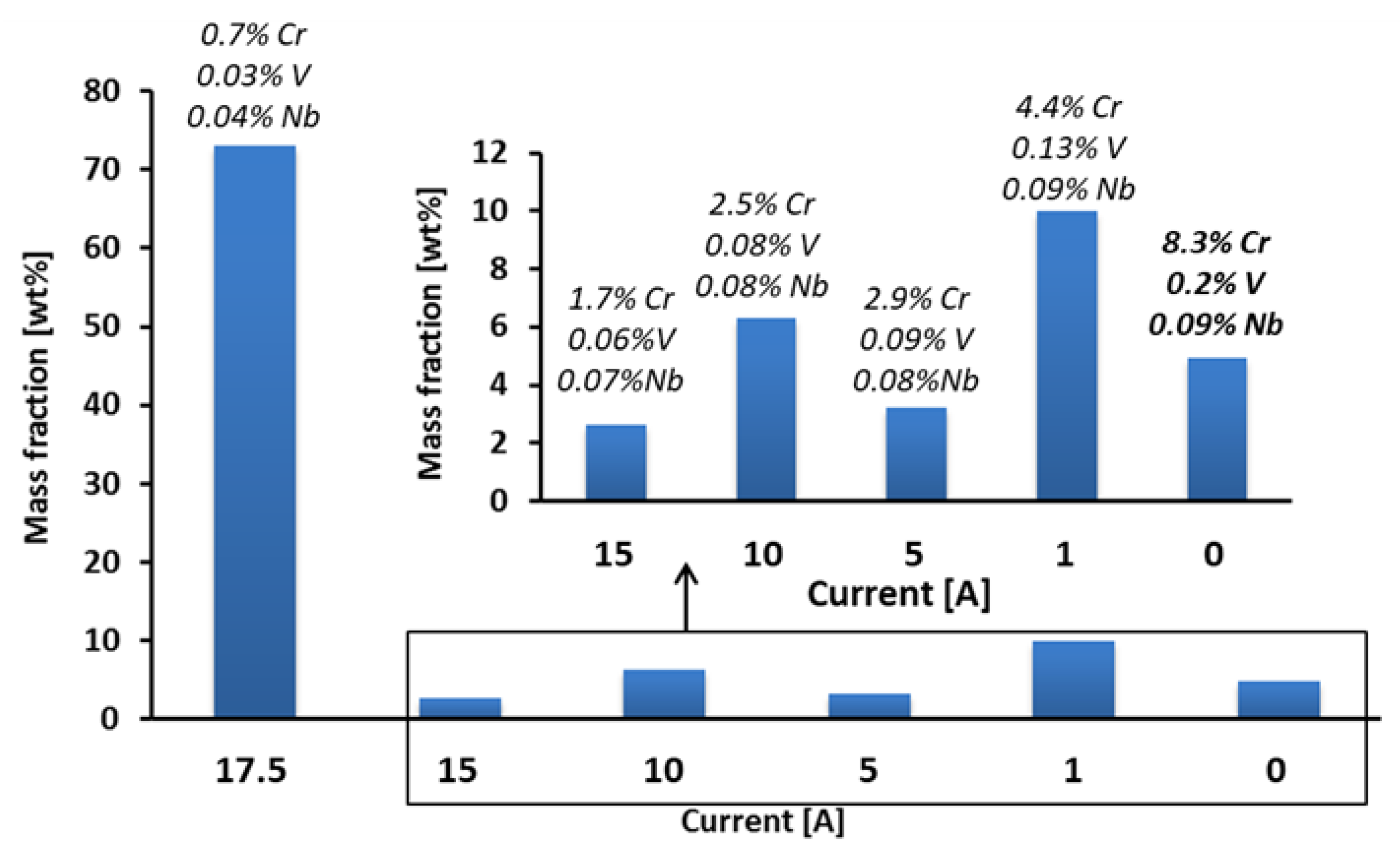
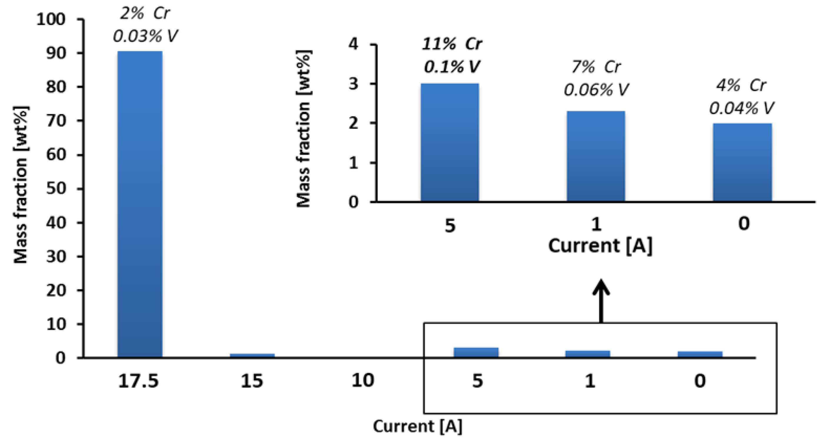
During sequential WHIMSe separation, similar Cr up-concentration (but also V and Nb) can be observed. As shown in Figure 3, the Cr content in the magnetic fractions increases with decreasing magnetic field, indicating than Cr-rich particles are those with the highest magnetic susceptibility. The highest Cr content (8.3 wt.%) was measured in the final magnetic fraction washed out at the lowest magnetic field (current 0 A). In this case the weight yield was 5% representing 21% Cr recovery in this fraction. On the other hand, the fraction washed out at the highest magnetic field (at 17.5 A), with a weight yield of 73%, contains only 0.7 wt.% Cr, and thus only 22% of the initial Cr. These results indicate that by performing a single WHIMSe separation at 17.5 A, the majority of the Cr can be removed from the matrix (non-magnetic) material.
3.2.2. Magnetic Separation—LC FeCr Slag
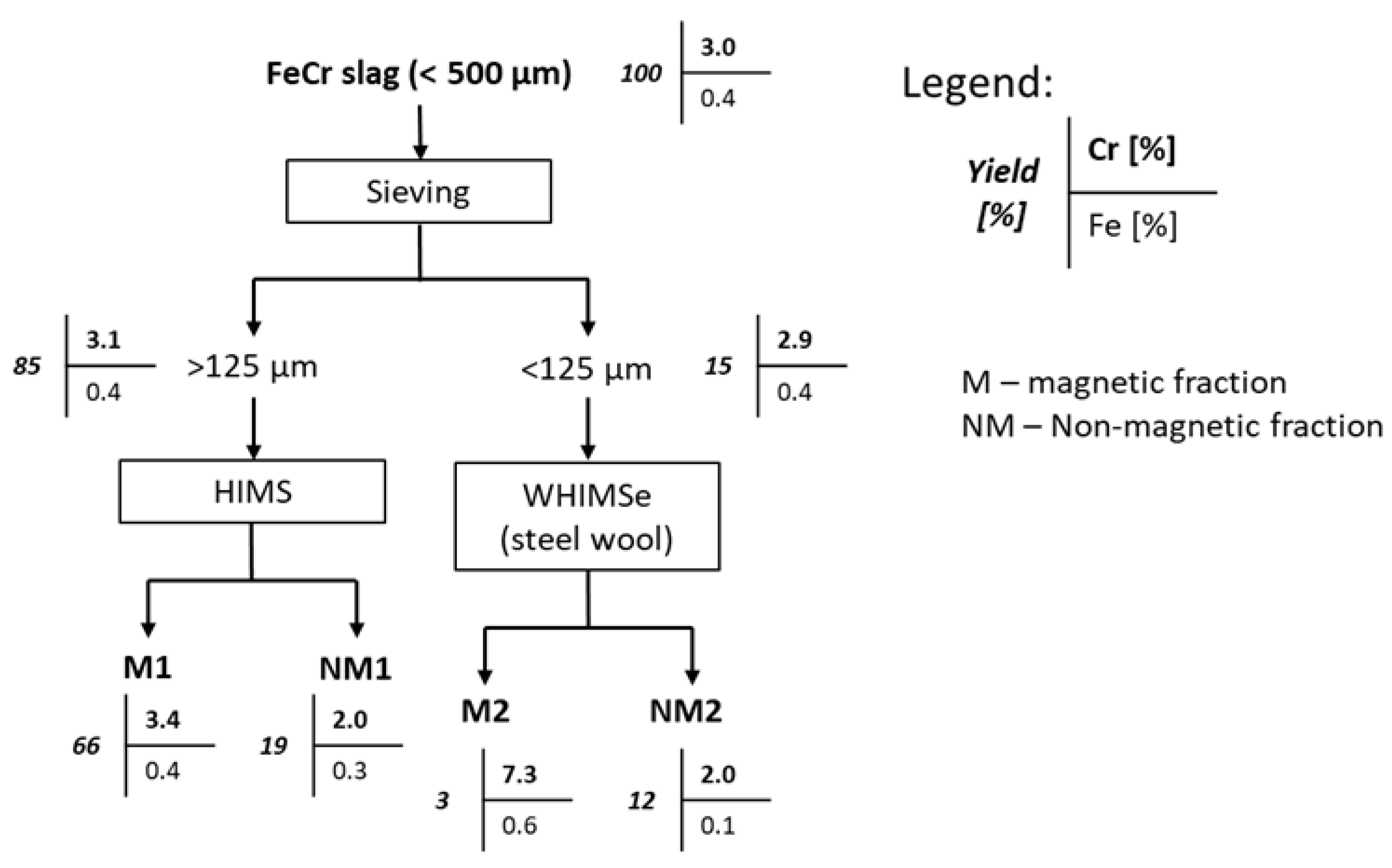
A combination of HIMS and WHIMSe was employed to process LC FeCr slag (size fraction <500 µm). The process flow with the mass balance and chemical composition of the different streams are shown in Figure 4.
As shown in Figure 4, the <500 µm fraction was first sieved into <125 μm and >125 μm fractions, which were treated by different techniques (dry vs. wet). Generally, in case of coarse particles (>75 μm) both dry or wet magnetic separation can be used, while in case of fine particles (<75 μm) wet magnetic separation is more appropriate [18]. HIMS was used to treat the fraction >125μm while single WHIMSe (at 17.5 A) was used for treating the fraction <125 μm.
The difference in Cr content before and after HIMS separation (3.1 wt.% vs 3.4 wt.%) was too small to justify the separation. On the other hand, treating the fraction <125 μm by WHIMSe shows a more significant Cr up-concentration in the magnetic fraction (M2) (7.3 wt.% vs. 2.9 wt.%). This might be explained by a better liberation of the Cr-rich phases in the fraction <125 μm as shown by SEM-EDS analysis (Figure 1b). However, the weight yield of fraction M2 was only 3%, representing only 7% Cr recovery.
Figure 5 shows the results of sequential WHIMSe on LC FeCr slag <125 mm with decreasing electric current. The fraction with the highest Cr content (11 wt.%) was obtained after washing at 5 A. The weight yield and Cr recovery were 3% and 14%, respectively.
Based on the results shown in Figure 4 and Figure 5, it can be concluded that to up-concentrate Cr present in LC FeCr slag by magnetic separation requires an additional milling step to liberate Cr-rich particles from the matrix. However, considering the very low yield and Cr recovery, the economic feasibility of using a magnetic separation for LC FeCr slag is questionable.
3.2.3. Magnetic Separation—HC FeCr Slag
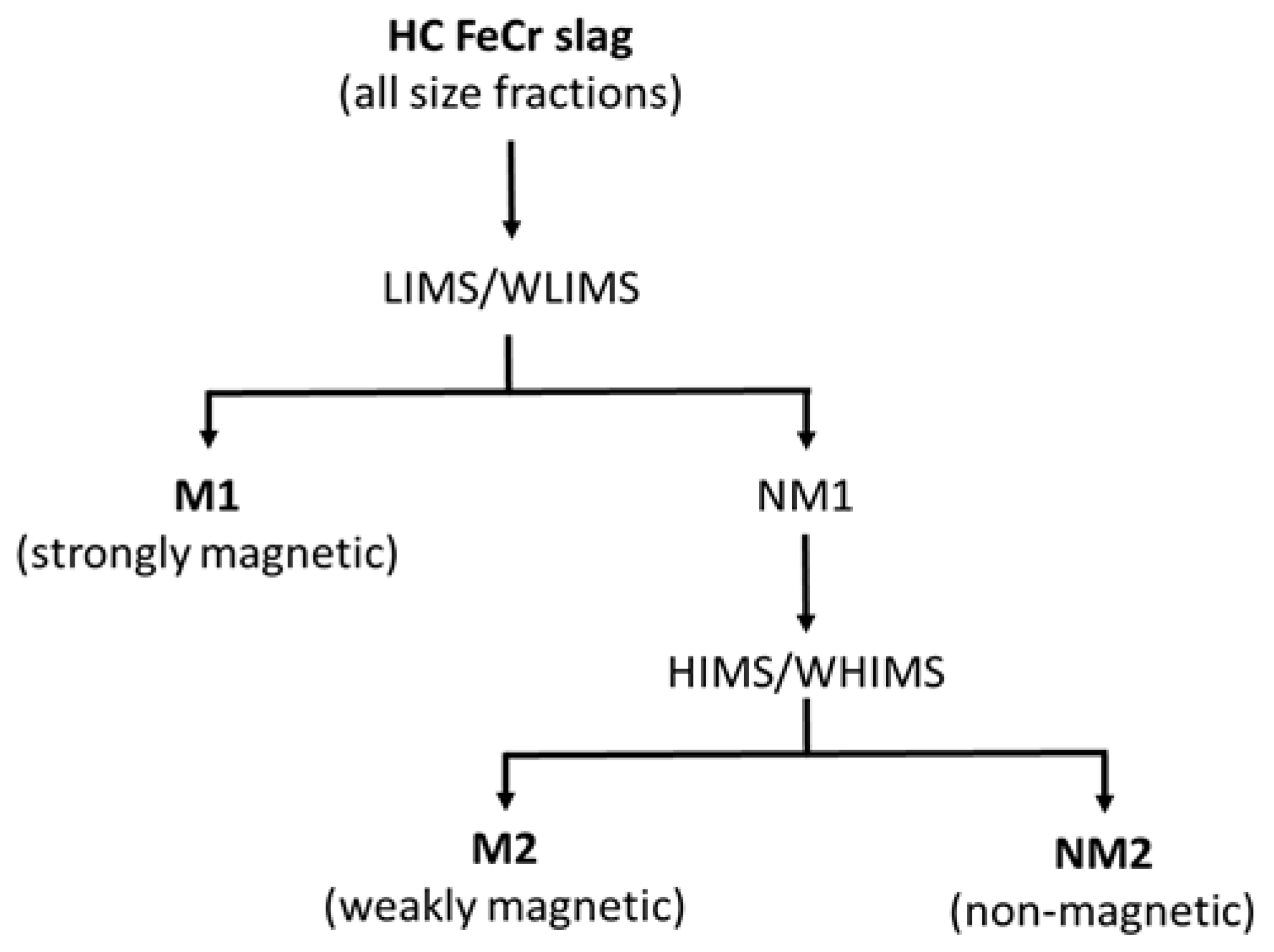
A combination of low and high intensity magnetic separation techniques was used to separate a Cr-rich phase from a Si-rich matrix. As observed in the SEM images (Figure 1c), relatively large fully liberated FeCr particles of around 500 µm diameter, can be found in the HC FeCr slag. For this reason, magnetic separation tests were performed on a wide range of particle sizes (from <125 µm to >2 mm). Depending on the particle size either dry or wet magnetic separation techniques were used. The fractions >500 μm were separated by dry magnetic separation and the fractions < 500 μm by wet magnetic separation techniques. Figure 6 shows the separation process with three final output fractions.
Before magnetic separation, the material was split into different size fractions. Chemical analysis of all size fractions (Table 4) clearly showed that Cr tends to concentrate in the smallest size fractions (<125 μm and 125–250 μm). As Cr is mostly present as a FeCr alloy, the Fe content follows the same trend.
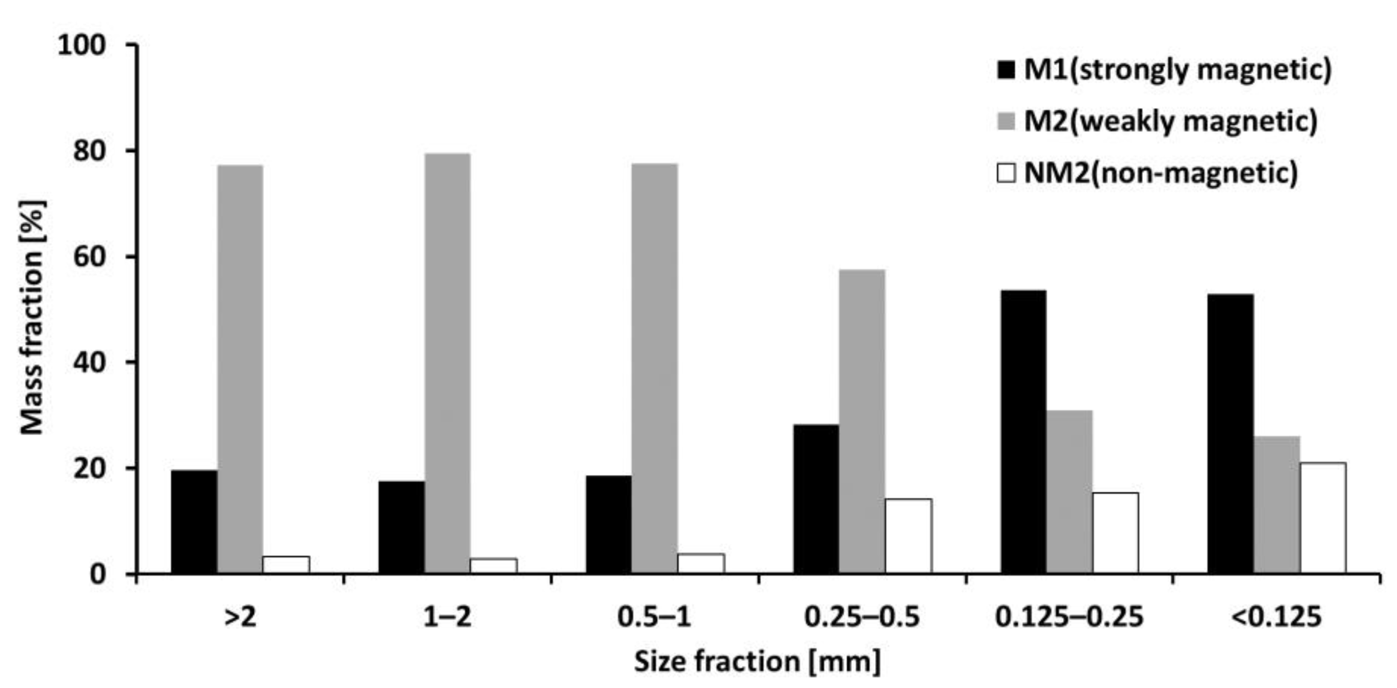
All size fractions were subjected to the magnetic separation according to Figure 6. As shown in Figure 7, the amount of the strongly magnetic fraction (M1) increased with decreasing particle size indicating that FeCr particles are mainly present as particles smaller than 250 µm.
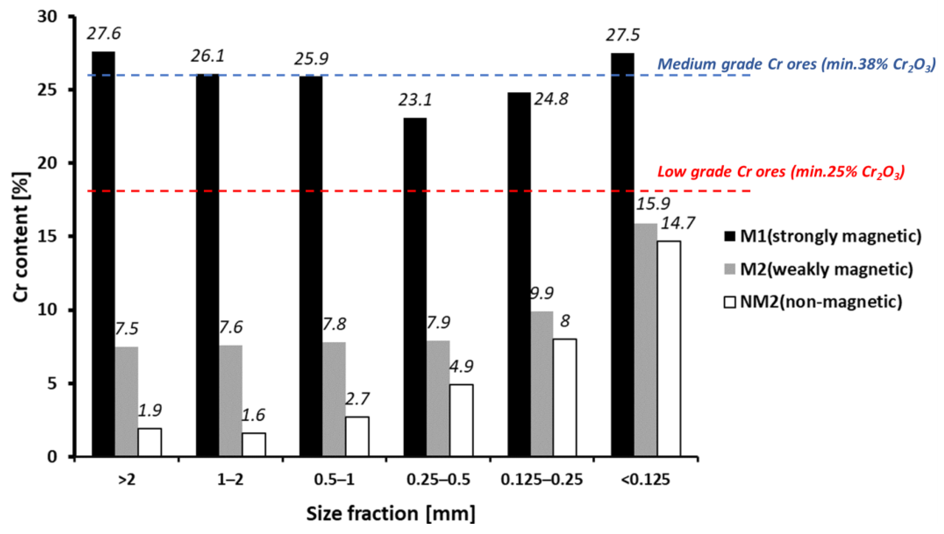
Figure 8 clearly shows that Cr is concentrated in the M1 fraction up to a level comparable with Cr ores of different grades (dashed lines in Figure 8). As expected, Fe also tends to concentrate in the M1 fractions (Supplementary Materials, Figure S4) while Si concentrates more in the non-magnetic (NM2) fractions (Supplementary Materials, Figure S5).
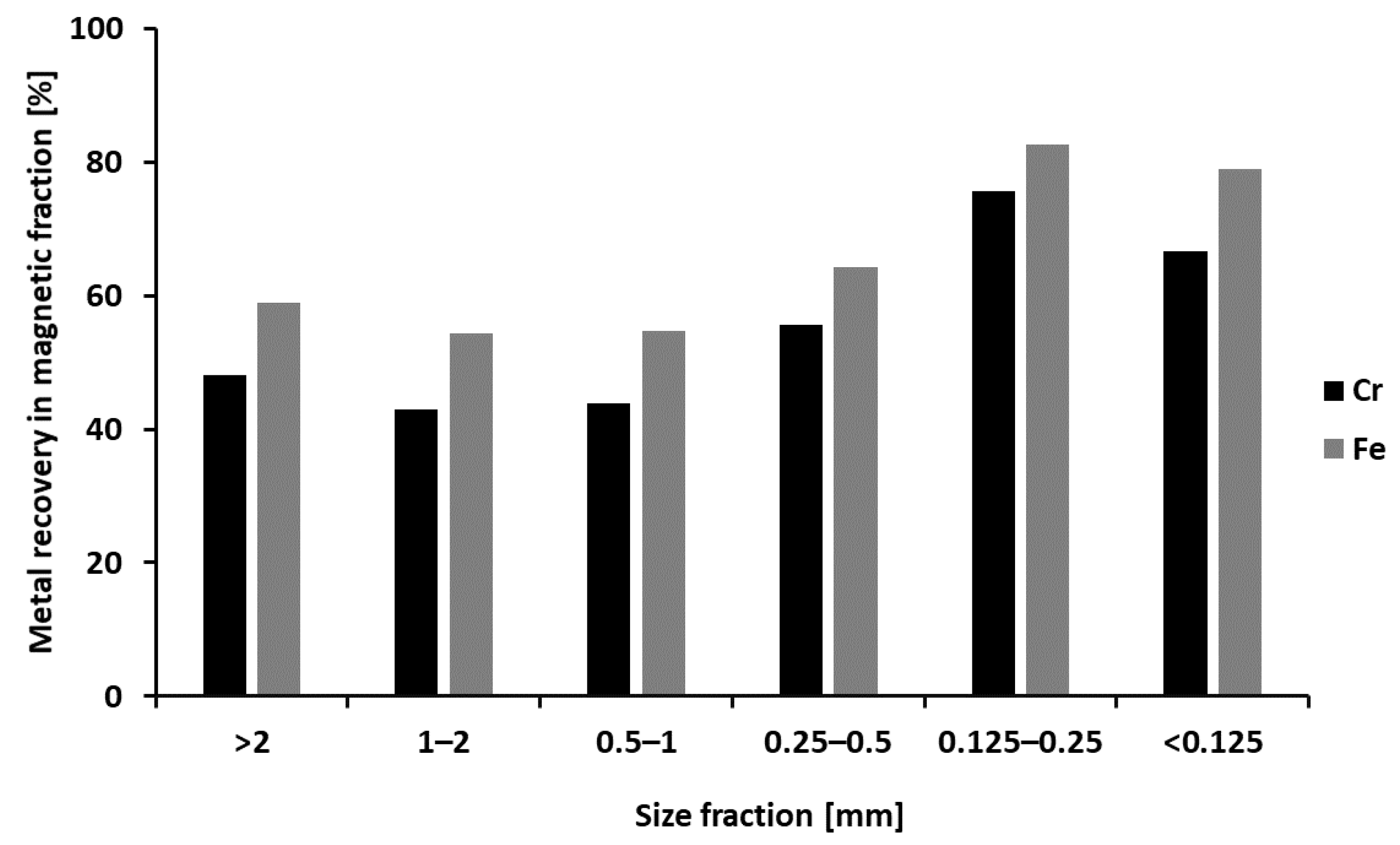
The final recoveries of Cr and Fe are shown in Figure 9. The highest recoveries of Cr and Fe (76% and 86%) were obtained for size fraction 125–250 µm. This is mainly due to the better liberation of Cr (and Fe) rich phases. A slightly lower recovery for the fraction < 125 μm can be caused by the presence of very fine particles, which are difficult to separate even by wet magnetic separation.
3.3. Results of Gravity Separation
Gravity Separation—HC FeCr Slag
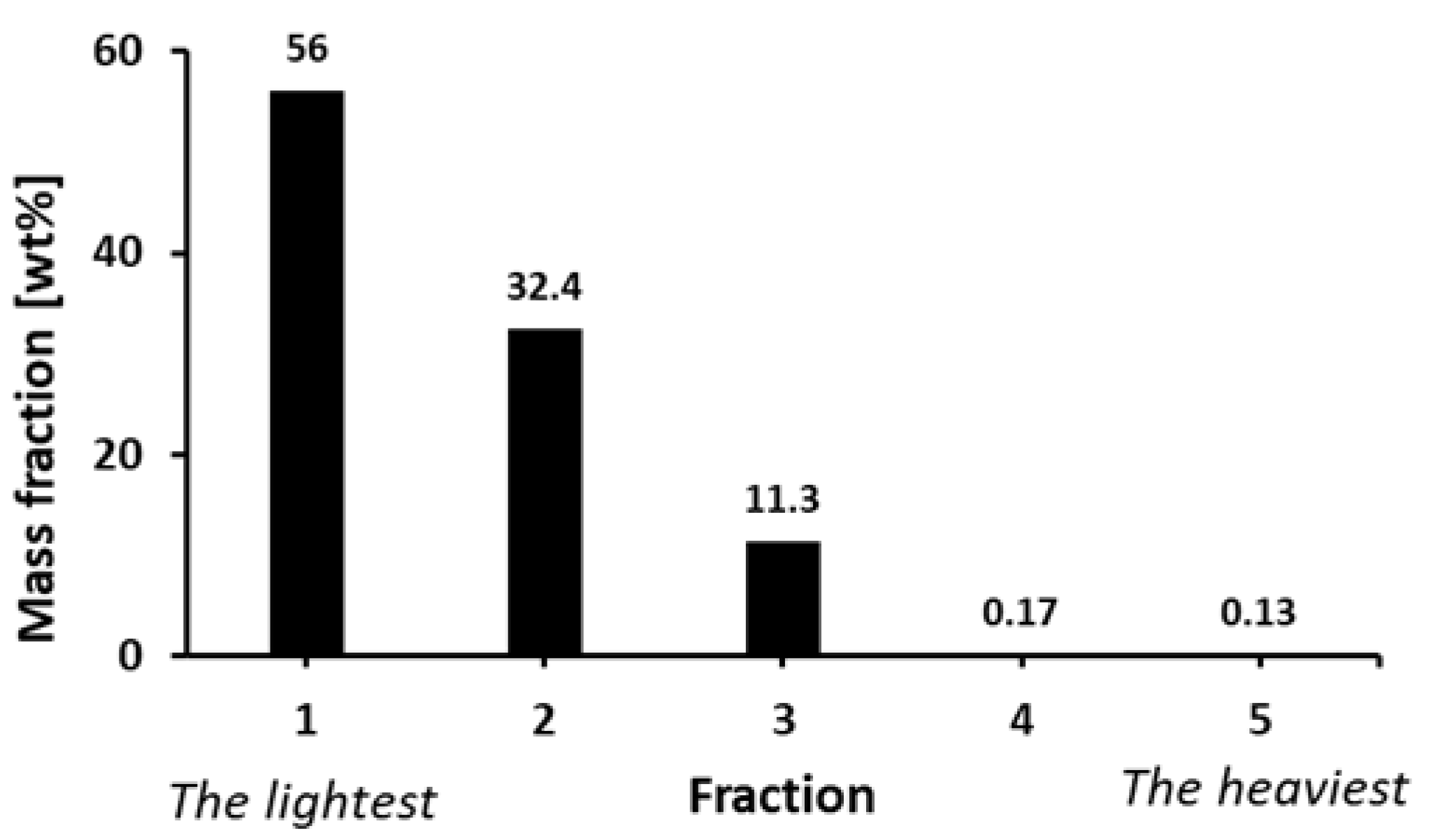
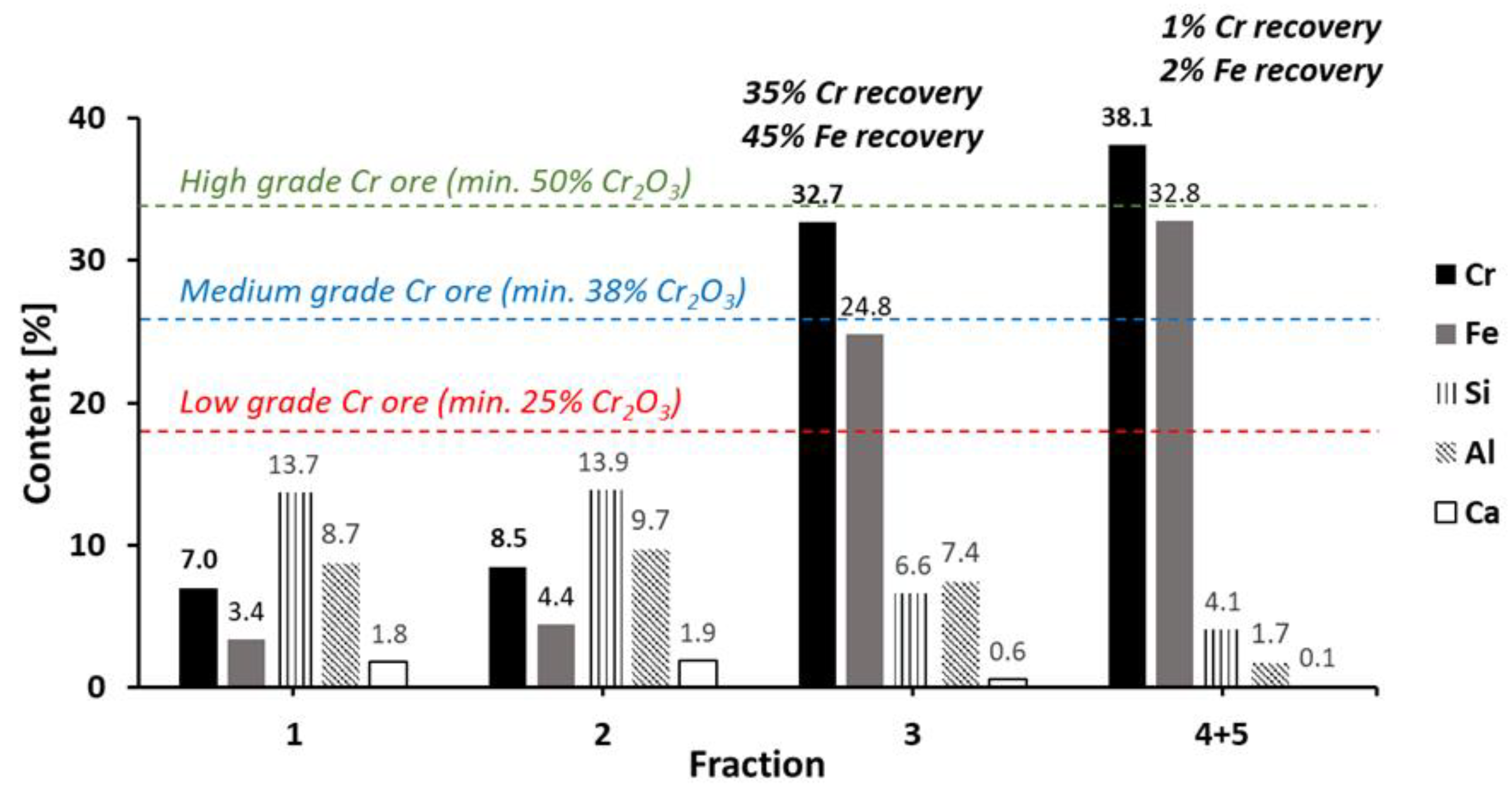
Five fractions (Supplementary Materials, Figure S6) were obtained after the gravity separation of HC FeCr slag (size fraction 1–2 mm) using a wet shaking table (WST). The mass balance of the output fractions is shown in Figure 10. After separation, all fractions were dried (24 h at 40 °C) and milled below <125 µm for XRF analysis. Results of XRF analysis are shown in Figure 11. Due to the very small amounts and visual similarity between fractions 4 and 5, these two fractions were combined and analyzed as one fraction.
The combined fraction (4 + 5) contains more than 38 wt.% Cr and has a Cr content comparable with high grade Cr ores. However, this fraction represents only 0.3 wt.% of the initial material. By further combining with fraction 3, the Cr content of the combined sample would stay high (>32 wt.% Cr) and the weight yield would increase to almost 12 wt.%, representing 36% Cr recovery. This material could possibly be used as a replacement for primary high grade Cr ores in FeCr production plants.
4. Discussion
By using magnetic separation, the Cr content of SS slags can be increased fourfold up to 8.8 wt.% with 31% Cr recovery. While the obtained concentrations are too low to recover Cr by traditional pyrometallurgical processes, the up-concentration can be beneficial for the application in alternative hydrometallurgical processes. Such processes can be based on heap leaching [19], alkaline pressure leaching or alkaline roasting followed by water leaching where after selective Cr removal, the Cr-depleted matrix can be used as a construction material [20,21]. As the capacity of hydrometallurgical facilities (especially those working at hydrothermal conditions) are often limited, reducing the amount of material to treat by preparing an up-concentrated fraction prior to the leaching step can be beneficial.
The Cr content in LC FeCr slag can be increased from 3% up to 11% by sequential WHIMSe separation. However, in this case the weight yield (3 wt.%) and total Cr recovery (14%) are relatively low. Moreover, to achieve such Cr up-concentration, the slag needs to be milled down to <125 µm, what incurs additional costs. Considering the facts above, the economic feasibility of processing this LC FeCr slag by magnetic separation is questionable.
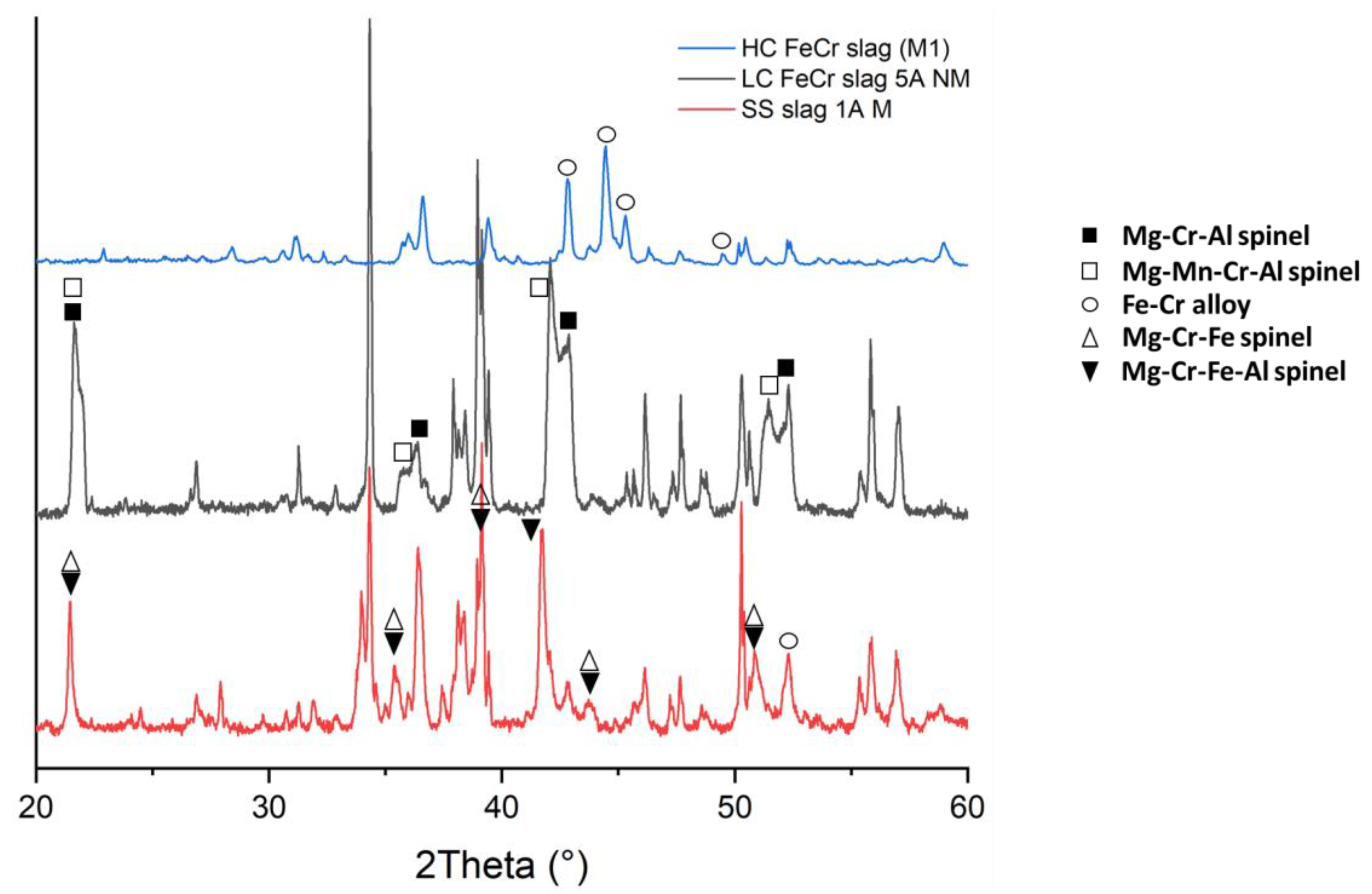
Cr content in HC FeCr slag can be increased by single step LIMS/WLIMS to the level comparable with medium grade ores. This can be achieved due to the presence of well liberated Cr-rich grains in the initial material (as shown by SEM in Figure 1c). XRD analysis of the up-concentrated magnetic fraction (Figure 12) showed that except of Cr-spinels also metallic Fe-Cr particles can be clearly identified. However, Cr content in up-concentrated magnetic fractions was still below the typical requirements (>49% Cr2O3) for using it as input material for smelting of FeCr. Additional Cr up-concentration can be achieved, for instance, by combining magnetic and gravity separation and/or combining different gravity separation techniques in one process as demonstrated by Can et al. [22].
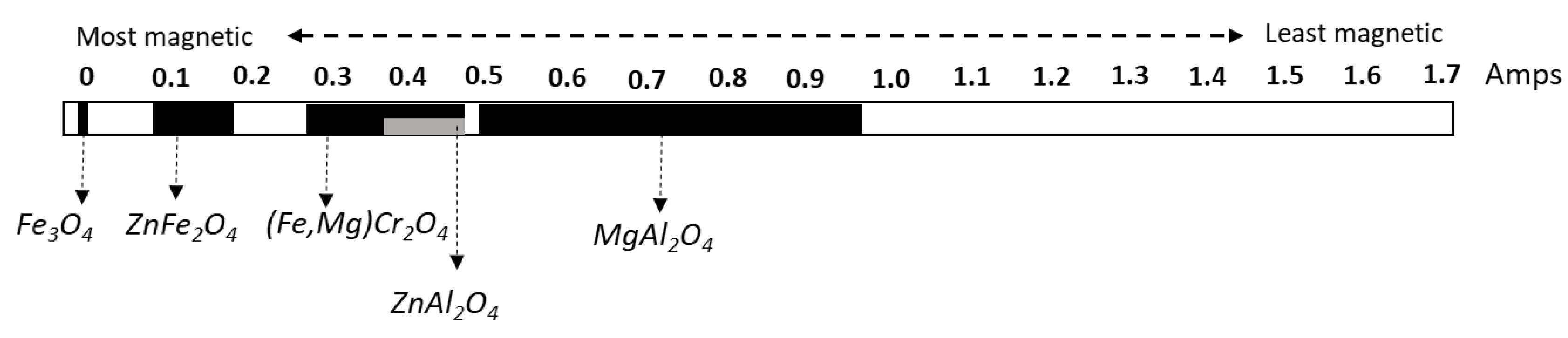
Although, SS slag and LC FeCr slag have very similar chemical and mineralogical compositions, there are significant differences in Cr up-concentration after magnetic separation. This can be explained by different Cr-containing spinels present in both samples. As shown in Figure 12, in case of LC FeCr slag, the Cr containing spinels were represented by Mg-Cr-Al and Mg-Mn-Cr-Al spinels, while in SS slag it was mainly Mg-Cr-Fe and Mg-Cr-Fe-Al spinels. Even though all those spinels have the same structure (cubic, space group Fd-3m) different metal cations present in the structure can be responsible for different magnetic susceptibility, and thus a slightly different behavior in a magnetic field. The presence of Fe in the Mg-Cr-Fe spinels, in case of SS slag, can explain why Cr was concentrated mostly in the most magnetic fraction while in case of LC FeCr slag, the Cr rich fraction was obtained as a weak-magnetic fraction at 5A. As shown in Figure 13, compounds with spinel structure containing Fe in their lattice are more magnetic compared to those without Fe.
In case of gravity separation of HC FeCr slag, the Cr content in the heaviest fractions can be increased by a factor of more than three to the level comparable with high grade ores, which might be used directly in FeCr production. Light fractions after gravity separation, containing 7.0 and 8.5 wt.% Cr, might be processed, in a similar way as the up-concentrated fraction of SS slags, i.e., by hydrometallurgical methods to selectively remove Cr and enable full valorization of the Cr-depleted matrix in construction industry.
In comparison with other studies (summarized in a review paper of Murphy et al. [14]), where the aim was to up-concentrate Cr in low grade ores by applying gravity and magnetic separation techniques, reported Cr up-concentrations were rarely above a factor of two. Moreover, in order to reach such up-concentrations, a combination of different separation techniques was used (e.g., shaking table and WHIMS). Results of our study clearly show that even one-step gravity separation of HC FeCr slag, can lead to Cr up-concentration by a factor of more than three to the level of high grade Cr ore, with 35% of Cr recovery. This is caused by the presence of metallic Fe-Cr particles (mainly in HC FeCr slag, as shown in Figure 12) which due to higher magnetic susceptibility and density can be separated from the matrix (mostly Ca-Mg-Al silicates) more easily. This proves, that HC FeCr slag can already be considered, after magnetic or gravity separation, as a replacement for medium or even high grade primary ores used in FeCr production. Reusing a part of FeCr slag back in FeCr production could help to accelerate the transition to a circular economy in FeCr industry.
5. Conclusions
Magnetic and gravity separation techniques were investigated in order to up-concentrate Cr in Cr-containing slags coming from SS and FeCr productions. Results of this study clearly show potential for applying of these beneficiation methods in processing SS and HC FeCr slags.
In case of SS slag, Cr up-concentration up to almost 9 wt.% can be obtained by WHIMS. As this Cr content is still low for FeCr production, this can be considered as a pre-treatment step prior to hydrometallurgical Cr recovery. Although, similar Cr up-concentration by using WHIMSe was obtained also in case of LC FeCr slag, in this case due to required milling and low yield (3 wt.%) such treatment would not be economically feasible. In case of HC FeCr slag, both magnetic and gravity separation resulted in an up-concentrated fraction with a Cr content comparable with commercial primary Cr ores. Especially, when gravity separation by wet shaking table was applied on 1–2 mm HC FeCr slag, material comparable with high grade Cr ores was obtained.
Supplementary Materials
The following are available online at https://www.mdpi.com/2075-163X/10/10/906/s1, Figure S1: Magnetic separation equipment used: (a) LIMS/HIMS, (b) WLIMS/WHIMS, and (c) WHIMSe.; Figure S2: Relation between current (in Amperes) and magnetic field (in Gauss)—provided by the equipment manufacturer Master Magnets Ltd.; Figure S3: The WST (wet shaking table) with the indication of the output fractions.; Figure S4: Fe content after magnetic separation of HC FeCr slag.; Figure S5: Si content after magnetic separation of HC FeCr slag. Figure S6: Output fractions after WST separation of HC FeCr slag (fraction 1–2 mm).
Author Contributions
Conceptualization, F.K. and P.N.; writing—original draft preparation, F.K.; writing—review and editing, F.K., P.N., and L.H.; funding acquisition, L.H. All authors have read and agreed to the published version of the manuscript.
Funding
This research was funded by the European Union’s Horizon 2020 Research and Innovation program under Grant Agreement no 730471.
Conflicts of Interest
The authors declare no conflict of interest. The funders had no role in the design of the study; in the collection, analyses, or interpretation of data; in the writing of the manuscript, or in the decision to publish the results.
References
- International Stainless Steel Forum (ISSF) Shanghai, Stainless Steel in Figures 2018. 2018. Available online: http://www.worldstainless.org/Files/issf/non-imagefiles/PDF/ISSF_Stainless_Steel_in_Figures_2018_English_Public.pdf (accessed on 24 June 2020).
- Salman, M.; Dubois, M.; Di Maria, A.; Van Acker, K.; Van Balen, K. Construction Materials from Stainless Steel Slags: Technical Aspects, Environmental Benefits, and Economic Opportunities. J. Ind. Ecol. 2016, 20, 854–866. [Google Scholar] [CrossRef]
- Horckmans, L.; Möckel, R.; Nielsen, P.; Kukurugya, F.; Vanhoof, C.; Morillon, A.; Algermissen, D. Multi-Analytical Characterization of Slags to Determine the Chromium Concentration for a Possible Re-Extraction. Minerals 2019, 9, 646. [Google Scholar] [CrossRef] [Green Version]
- Euroslag, Statistics 2016. Available online: https://www.euroslag.com/wp-content/uploads/2019/01/Statistics-2016.pdf (accessed on 24 June 2020).
- Karhu, M.; Talling, B.; Piotrowska, P.; Matas Adams, A.; Sengottuvelan, A.; Huttunen-Saarivirta, E.; Boccaccini, A.R.; Lintunen, P. Ferrochrome Slag Feasibility as a Raw Material in Refractories: Evaluation of Thermo-physical and High Temperature Mechanical Properties. Waste Biomass Valorizat. 2020. [Google Scholar] [CrossRef]
- Mombelli, D.; Mapelli, C.; Barella, S.; Di Cecca, C.; Le Saout, G.; Garcia-Diaz, E. The effect of chemical composition on the leaching behaviour of electric arc furnace (EAF) carbon steel slag during a standard leaching test. J. Environ. Chem. Eng. 2016, 4, 1050–1060. [Google Scholar] [CrossRef] [Green Version]
- Zhao, Q.; Liu, C.; Cao, L.; Zheng, X.; Jiang, M. Stability of chromium in stainless steel slag during cooling. Minerals 2018, 8, 445. [Google Scholar] [CrossRef] [Green Version]
- Kotas, J.; Stasicka, Z. Chromium occurence in the environment and methods of its speciation. Environ. Pollut. 2000, 107, 263–283. [Google Scholar] [CrossRef]
- Cheremisina, E.; Schenk, J. Chromium Stability in Steel Slags. Steel Res. Int. 2017, 87, 1–7. [Google Scholar] [CrossRef]
- European Commission, Critical Raw Materials. Available online: https://ec.europa.eu/growth/sectors/raw-materials/specific-interest/critical_en (accessed on 30 June 2020).
- Seuker, J. Chromium. In Environmental Forensics: Contaminant Specific Guide; Morrison, R.D., Murphy, B., Eds.; Elsevier Inc.: Amsterdam, The Netherlands, 2006; pp. 81–93. [Google Scholar]
- Gianluca, C.; Rodrigo Gonzalo, M.; Farrell, F.; Roudier, S.; Remus, R.; Delgado Sancho, L. Best Available Techniques (BAT) Reference Document for the Main Non-Ferrous Metals Industries; European Commission: Brussels, Belgium, 2017. [Google Scholar] [CrossRef]
- Gasik, M.I. Technology of Chromium and Its Ferroalloys. Handb. Ferroalloys 2013. [Google Scholar] [CrossRef]
- Murthy, Y.R.; Tripathy, S.K.; Kumar, C.R. Chrome ore benefication challenges & opportunities—A review. Miner. Eng. 2011, 24, 375–380. [Google Scholar]
- Tripathy, S.K.; Banerjee, P.K.; Suresh, N. Magnetic separation studies on ferruginous chromite fine to enhance Cr:Fe ratio. Int. J. Miner. Metall. Mater. 2015, 22, 217–224. [Google Scholar] [CrossRef]
- Tripathy, S.K.; Singh, V.; Ramamurthy, Y. Improvement in Cr:Fe Ratio of Indian Chromite Ore for Ferro Chrome Production. Int. J. Min. Eng. Miner. Process. 2012, 1, 101–106. [Google Scholar] [CrossRef]
- Tripathy, S.K.; Murthy, Y.R.; Singh, V.; Suresh, N. Processing of ferruginous chromite ore by dry high-intensity magnetic separation. Miner. Process. Extr. Metall. Rev. 2016, 37, 196–210. [Google Scholar] [CrossRef]
- Svoboda, J. Magnetic Techniques for the Treatment of Materials; Kluwer Academic Publishers: Dordrecht, The Netherlands, 2004. [Google Scholar]
- Spooren, J.; Kim, E.; Horckmans, L.; Broos, K.; Nielsen, P.; Quaghebeur, M. In-situ chromium and vanadium recovery of landfilled ferrochromium and stainless steel slags. Chem. Eng. J. 2016, 303, 359–368. [Google Scholar] [CrossRef]
- Kim, E.; Spooren, J.; Broos, K.; Nielsen, P.; Horckmans, L.; Geurts, R.; Vrancken, K.C.; Quaghebeur, M. Valorization of stainless steel slag by selective chromium recovery and subsequent carbonation of the matrix material. J. Clean. Prod. 2016, 117, 221–228. [Google Scholar] [CrossRef] [Green Version]
- Gu, F.; Zhang, Y.; Peng, Z.; Su, Z.; Tang, H.; Tian, W.; Liang, G.; Lee, J.; Rao, M.; Li, G.; et al. Selective recovery of chromium from ferronickel slag via alkaline roasting followed by water leaching. J. Hazard. Mater. 2019, 374, 83–91. [Google Scholar] [CrossRef] [PubMed]
- Can, İ.B.; Özsoy, B.; Ergün, Ş.L. Developing an optimum beneficiation route for a low-grade chromite ore. Physicochem. Probl. Miner. Process. 2019. [Google Scholar] [CrossRef]
- USA Geological Survey, Magnetic Susceptibilities of Minerals, Reston, VA. 2000. Available online: https://doi.org/10.3133/ofr99529 (accessed on 24 June 2020).
Figure 1.
SEM-Backscattered Electron (BSE) images of (a) SS slag,(b) LC FeCr slags and (c) HC FeCr slag. SS = stainless steel, Ca = Ca- silicates, A = CaMgAl-silicates, Cr = Cr-rich spinel phase, P = Periclase, Sp = spinel, FeCr = Ferrochrome particle. Phase identifications are based on SEM-EDS analysis.

Figure 2.
Processing of SS slag by combination of WHIMS and WHIMSe.

Figure 3.
Results of the sequential WHIMSe separation for SS slag.

Figure 4.
Processing flowsheet for LC FeCr slag.

Figure 5.
Results of sequential WHIMSe separation for LC FeCr slag-fraction <125 µm.

Figure 6.
Combination of low and high intensity magnetic separation used for HC FeCr slag. (LIMS and HIMS for fractions >500 µm and WLIMS and WHIMS for fractions <500 µm).
Figure 6.
Combination of low and high intensity magnetic separation used for HC FeCr slag. (LIMS and HIMS for fractions >500 µm and WLIMS and WHIMS for fractions <500 µm).

Figure 7.
Mass balance after separation for all size fractions of HC FeCr slag.

Figure 8.
Cr content after magnetic separation of HC FeCr slag (Cr ores grades according to [13]).
Figure 8.
Cr content after magnetic separation of HC FeCr slag (Cr ores grades according to [13]).

Figure 9.
Recovery of Cr and Fe after magnetic separation of HC FeCr slag in M1 fraction.

Figure 10.
Mass balance after WST separation of HC FeCr slag (fraction 1–2 mm).

Figure 11.
Content of metals in different fractions after WST (Cr ores grades according to [13]).
Figure 11.
Content of metals in different fractions after WST (Cr ores grades according to [13]).

Figure 12.
XRD patterns showing Cr-phases in the most up-concentrated fractions of SS, LC FeCr, and HC FeCr slag (not identified peaks belong mostly to Ca-(Mg-Al-)silicates like merwinite, bredigite, and akermanite).
Figure 12.
XRD patterns showing Cr-phases in the most up-concentrated fractions of SS, LC FeCr, and HC FeCr slag (not identified peaks belong mostly to Ca-(Mg-Al-)silicates like merwinite, bredigite, and akermanite).

Figure 13.
Magnetic properties of different spinel structures [23].
Figure 13.
Magnetic properties of different spinel structures [23].


Table 1.
Magnetic separation techniques tested in this study.
| Abbreviation | Description (Type) | Magnetic Field Strength (Tesla) | Tested Material (Size Fraction) |
|---|---|---|---|
| LIMS | Dry low intensity magnetic separation (Handheld ferrite magnet) | 0.15 | HC 1 FeCr slag (0.5–4 mm) |
| HIMS | Dry high intensity magnetic separation (Handheld REE 2 magnet) | 1 | LC 1 FeCr slag (0.125–0.5 mm) HC FeCr slag (0.5–4 mm) |
| WLIMS | Wet low intensity magnetic separation (Wetchute with ferrite magnet) | 0.15 | HC FeCr slag (<0.5 mm) |
| WHIMS | Wet high intensity magnetic separation (Wetchute with REE magnet) | 0.8 | SS 1 slag (<0.15 mm) HC FeCr slag (<0.5 mm) |
| WHIMSe | Wet high gradient/intensity magnetic separation (WHIMS 500) | 0–2 | SS slag (<0.15 mm) LC FeCr slag (<0.125 mm) |
1 HC—High carbon; LC—Low carbon; SS—stainless steel. 2 REE—Rare-earth elements.
Table 2.
Conditions for wet shaking table (WST) separation of HC FeCr slag (fraction 1–2 mm).
| Parameter | Value | Unit |
|---|---|---|
| stroke speed | 250 | rpm |
| washing water flow | 1000 | L/h |
| feed dilution water | 250 | L/h |
Table 3.
Chemical composition of the studied slags.
| Element/Oxide | Units | SS Slag | LC FeCr Slag | HC FeCr Slag 2 |
|---|---|---|---|---|
| Al2O3 | wt.% | 4.2 ± 0.5 | 7.2 ± 0.6 | 17.9 |
| CaO | wt.% | 45.1 ± 2.6 | 43.0 ± 2.9 | 2.5 |
| Fetot. | wt.% | 0.6 ± 0.1 | 0.3 ± 0.1 | 6.4 |
| MgO | wt.% | 11.0 ± 1.8 | 14.0 ± 1.8 | 15.8 |
| MnO | wt.% | 1.1 ± 0.2 | 0.1 ± 0.01 | 0.2 |
| SiO2 | wt.% | 30.8 ± 5.6 | 30.3 ± 2.9 | 29.1 |
| V2O5 | wt.% | 0.09 ± 0.03 | 0.06 ± 0.02 | 0.09 |
| Cr | wt.% | 2.3 ± 0.5 | 3.2 ± 0.4 | 11.5 |
| Mo | mg/kg | 40 1 | <5 | <5 |
| Nb | mg/kg | 617 1 | <5 | <5 |
1 Only 1 measurement. 2 Measured by Handheld XRF as a powder.
Table 4.
Chemical composition of different size fractions after sieving (HC FeCr slag).
| Fraction | Yield (wt.%) | Content (wt.%) | ||||
|---|---|---|---|---|---|---|
| Fe | Cr | Ca | Al | Si | ||
| 2–4 mm | 10.9 | 6.8 | 8.7 | 1.8 | 10.9 | 13.7 |
| 1–2 mm | 20.4 | 5.2 | 10.1 | 1.9 | 9.9 | 13.8 |
| 0.5–1 mm | 25.5 | 5.0 | 9.4 | 1.9 | 9.5 | 13.3 |
| 250–500 µm | 17.9 | 5.9 | 10.7 | 1.9 | 9.8 | 13.8 |
| 125–250 µm | 14.8 | 8.8 | 14.8 | 1.7 | 10.5 | 13.6 |
| <125 µm | 10.1 | 10.9 | 16.8 | 1.8 | 11.2 | 12.8 |
| Total | 100 | 6.5 | 11.2 | 1.8 | 10.1 | 13.5 |
© 2020 by the authors. Licensee MDPI, Basel, Switzerland. This article is an open access article distributed under the terms and conditions of the Creative Commons Attribution (CC BY) license (http://creativecommons.org/licenses/by/4.0/).
Share and Cite
MDPI and ACS Style
Kukurugya, F.; Nielsen, P.; Horckmans, L. Up-Concentration of Chromium in Stainless Steel Slag and Ferrochromium Slags by Magnetic and Gravity Separation. Minerals 2020, 10, 906. https://doi.org/10.3390/min10100906
AMA Style
Kukurugya F, Nielsen P, Horckmans L. Up-Concentration of Chromium in Stainless Steel Slag and Ferrochromium Slags by Magnetic and Gravity Separation. Minerals. 2020; 10(10):906. https://doi.org/10.3390/min10100906
Chicago/Turabian StyleKukurugya, Frantisek, Peter Nielsen, and Liesbeth Horckmans. 2020. "Up-Concentration of Chromium in Stainless Steel Slag and Ferrochromium Slags by Magnetic and Gravity Separation" Minerals 10, no. 10: 906. https://doi.org/10.3390/min10100906
Note that from the first issue of 2016, this journal uses article numbers instead of page numbers. See further details here.