Influence of AISI D2 Workpiece Roughness on Heat Partition and Plasma Channel Radius in the WEDM Process


1
Department of Mechanical Engineering, Aeronautics Advanced Manufacturing Center, CFAA (UPV/EHU), Bizkaia Technology Park, Building 202, 48170 Zamudio, Spain
2
Department of Mechanical Engineering, UPV/EHU, Plaza Torres Quevedo 1, 48013 Bilbao, Spain
*
Author to whom correspondence should be addressed.
Metals 2020, 10(10), 1360; https://doi.org/10.3390/met10101360
Submission received: 10 September 2020
/
Revised: 5 October 2020
/
Accepted: 7 October 2020
/
Published: 12 October 2020
(This article belongs to the Special Issue State-of-Art within 3D Printing and Advanced Machining Processes)
Abstract
:As an important advanced machining process, in Wire Electrical Discharge Machining (WEDM) certain fundamental issues remain need to be studied in-depth, such as the effect of part surface roughness on heat transfer mechanisms. In the WEDM process, roughing cut wire goes into the workpiece to do the first shaping and in trim cut the wire sweeps on the outer surface to improve the surface roughness. In both of these two cases, the generation of sparks depends on the passing surface roughness. Therefore, with AISI D2 material and brass wire, this paper presents a study of the influence of part surface roughness on heat partition and the radius of the plasma channel in the WEDM process. Through extensive single discharge experiments, it is shown that the removal capacity per discharge can increase if the discharge occurs on a smoother surface. A Finite Element thermal model was then used for inverse fitting of the values of heat partition and radius of the plasma channel. These parameters completely define the characteristics of the heat conduction problem. The results indicate a strong correlation between an increase in heat partition ratio and a decrease in part surface roughness. The values of plasma channel radius show an increase in this value when discharging on rougher surfaces. It means that with the increasing of plasma channel radius, the heat source goes into the workpiece more dispersed. In the case of rougher surface, although the there is more area that affected by the heat source, finally the temperature of most area cannot reach to the melting point and it causes the smaller crater radius and volume, while the metal removal rate decreases. These results contribute towards a more complete understanding of the influence of surface roughness to the spark occurring.
1. Introduction
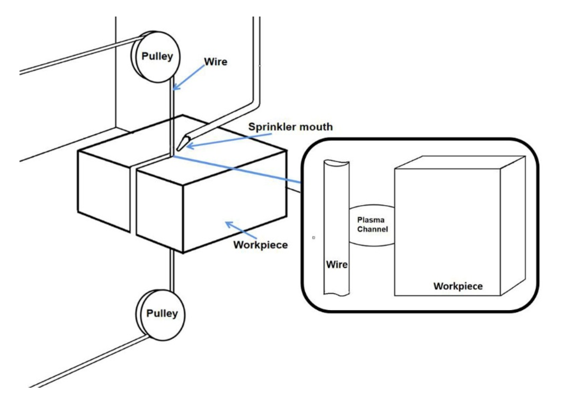
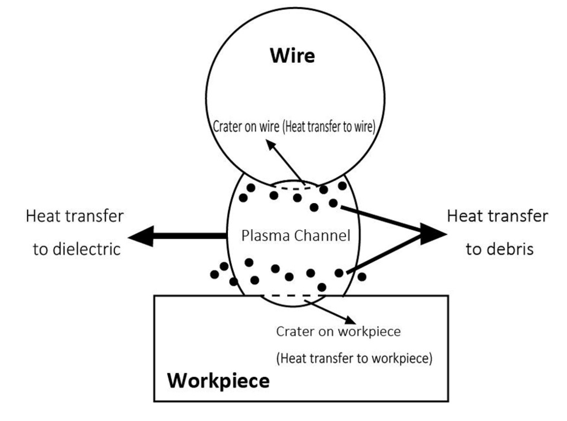
In the last few years, Wire Electrical Discharge Machining (WEDM) has played an important role in the field of advanced machining. Whether in the aerospace or the automatic machining sector, with greater flexibility and high machining accuracy, WEDM can satisfy most processing requirements while also considerably lowering costs. Therefore, to further master this advanced machining technology, more and more studies have been conducted to gain a more in-depth understanding of the WEDM process. As a kind of electro-erosion machining method, the WEDM system involves two electrodes—usually a metal wire (Cathode) and a conductive workpiece (Anode). Figure 1 briefly shows the working principle. The WEDM process is generally performed under immersion in deionized water, oil, or kerosene [1]. While machining is in process, a high number of discharges are generated between the surfaces of the two electrodes. By means of transfer through the plasma channel, a certain part of the heat is partitioned within the workpiece to achieve the objective of material removal. At the same time, the deionized water plays an important role not only in achieving plasma channel but also in cooling the working area and clearing away the debris. In addition, Figure 2 illustrates the plasma channel and it explained that the major heat source has transferred into four parts. They are, respectively, wire, workpiece, debris, and dielectric. The percentage of heat transfer from plasma channel to each part is called as heat partition.
A fundamental study of WEDM conducted by Kunieda et al. [2] that included both mechanical and electrical principles provided a basic insight into the WEDM process. Moreover, in recent years, a large amount of research has focused on improving the WEDM process combining this process with other advanced technologies. For instance, Radhakrishnane et al. [3] and Chu et al. [4] studied the removal rate and advantage of vibration-assisted WEDM. Moreover, in the works of Sanchez et al. [5] and Thankachan et al. [6], machine learning (including both unsupervised learning deep learning) was employed to detect defects in the WEDM process, including surface roughness and material removal rate. Thermal modeling is a useful method for restoring the internal heat transfer process through the simulation of WEDM discharge. In the works of both Izquierdo et al. [7] and Zhang et al. [8], the Finite Element Method (FEM) was applied to finish the construction of the thermal model. In these works, heat partition is critical and included as a fixed value, as in the study reported by Kunieda et al. [2], while plasma channel radius is always regarded as a variable value. Some clues can be initially seen in the work of Spur and Schönbeck [9] that they presented that the plasma channel radius changes depends on the time.
Given that surface roughness is a critical aspect of defining machining result, a considerable number of studies have been carried out with the aim of optimizing the WEDM parameters for the machining of different materials, such as the work of Kavimani et al. [10] and Mouralova et al. [11]. By judging the importance of machining parameters, they were able to improve the parameter settings. However, aside from the machining result, the way in which workpiece roughness influences the WEDM internal process is a matter of interest, and one that is worthy of investigation. The researches of Wang et al. [12] and Pandit et al. [13] suggest that the crater volume varies as a function of changes in surface roughness. Moreover, the WEDM cutting starts on a flat surface and then progresses on a rough surface. Depending on cutting regime (roughing or finishing), the surface roughness on which discharges occur also changes, whereas, as a controllable external machining condition, workpiece roughness is still not taken into account when attempting to understand the real machining process. In fact, the change of workpiece roughness could be helpful for finding the internal changes in heat transfer. With the change of workpiece surface roughness, some thermal changes could occur, such as heat partition and changes to plasma channel radius. The aim of this work is to provide an in-depth analysis of the underlying causes of this phenomenon.
Because of the thermal nature of the WEDM process, it becomes critical to have a thorough understanding of the mechanisms that govern heat transfer between wire and workpiece. Certain fundamental issues remain unclear, such as the effect of part surface roughness on heat transfer mechanisms. To the best of our knowledge, the work presented in this paper is the first attempt to examine the influence of part surface roughness on heat partition and on the radius of the plasma channel in the WEDM process. As it is known that in WEDM, roughing cut and trim cut are two essential processes for advanced manufacturing, whereas in these two kinds of cut, the wire works in the absolutely different condition. In roughing cut wire goes into the workpiece to do the first shaping. It means that in the whole cutting process sparks occur in a relatively rough surface, whereas in trim cut, the wire only sweep on the outer surface to realize the objective of improving surface roughness. In this process, all the generation of sparks depends on the roughness that outer surface. Therefore three kinds of surface roughness are taken into account in this work. First, surfaces with different roughness are prepared and through extensive single discharge experiments (Section 2), it is shown that removal capacity per discharge can increase as much as 40.4% if the discharge occurs on a smoother surface. A Finite Element thermal model (Section 3) is then used for inverse fitting of the values of heat partition and radius of the plasma channel. These parameters completely define the characteristics of the heat conduction problem. The results are discussed in Section 4, which show a strong correlation between an increase of heat partition ratio and a decrease in part surface roughness. The values of radius of the plasma channel are compatible with those found in other works in the literature. The deviation between the values of experimental and simulated crater diameters is below 1 µm for all of the part surfaces examined. These results contribute towards a more complete understanding of the influence of surface roughness to the spark occurring.
2. Materials and Methods
2.1. Experimental Procedures and Measurement of a Single Crater on Different Surfaces
In order to conduct an in-depth analysis of the influence of workpiece roughness on the heat partition, the real crater produced by WEDM machining under various conditions of surface roughness is needed. Therefore, the following experiments were planned. An AISI D2 (Table 1) metal workpiece of 50 mm thickness and CuZn37 brass wire of 0.25 mm diameter were, respectively, selected as the anode and cathode for study. Further, ONA AV-35 was chosen as the WEDM machine (ONA, Durango, Spain). As a first step, several workpiece surfaces of varying degrees of roughness need to be prepared. In this work, three kinds of surface roughness conditions were considered: flat surface, trim surface, and rough surface. The flat surface refers to the initial surface of the workpiece, trim surface is the surface resulting from a rough cut and double trim cut, whereas the rough surface is the one that remains after a rough cut. The specific parameters of WEDM are shown in Table 2.
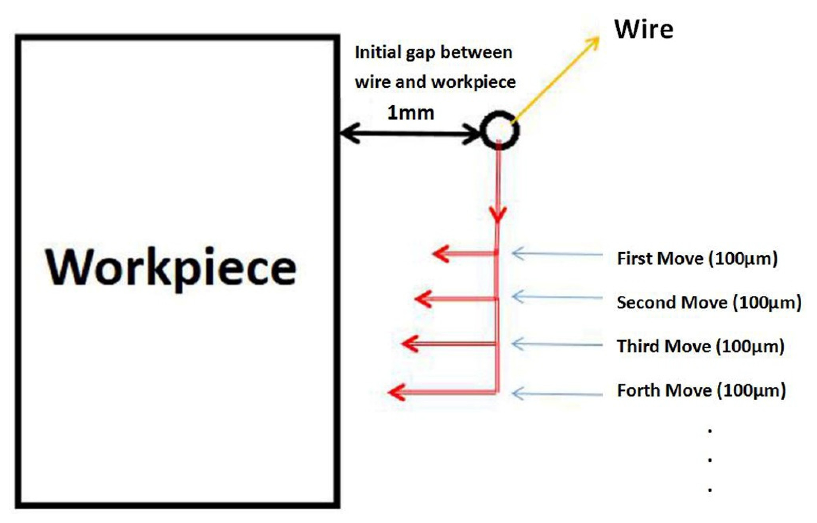
Given that there are different ways of processing the workpiece surface, three kinds of surface roughness are detected by the Mitutoyo SJ210 surface roughness tester (Mitutoyo, Kanagawa, Japan), the results of which are displayed in Table 3. Because of this, during the normal process of WEDM industrial machining, the discharges are continuous, and the craters will become connected so that it is almost impossible to study each individual crater. Therefore, with the objective of obtaining a clearly visible single crater on the prepared surfaces, another series of experiments was designed. One idea worth bearing in mind is the importance of finding the first touch between wire and workpiece. By means of the coordinate movement system of a WEDM machine, it is possible to monitor the moving distance of the wire. A number of adjustments allows for tracking the first craters that appear on the surface. As shown in Figure 3, first, the initial gap between wire and workpiece is controlled at 1 mm and then the wire is gradually positioned closer to the workpiece with every move of 100 µm until the first few sparks occur. This same process is repeated on the three surfaces of varying roughness, some parts of which are shown in Figure 4. Finally, from the single craters, 10 craters are chosen randomly for further observation and measurement.
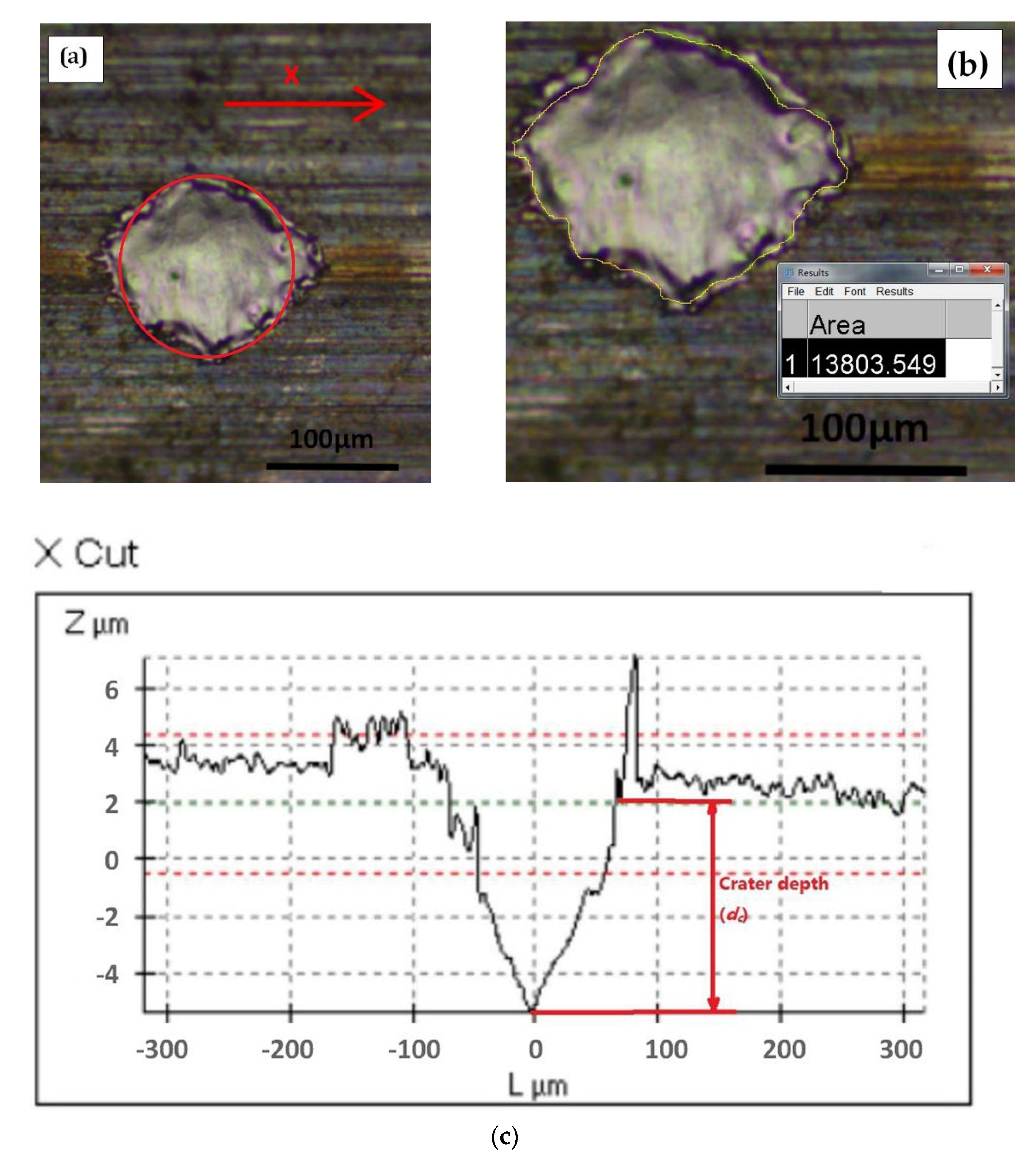
A Leica DCM3D profilometer (Leica Camera AG, Wetzlar, Germany) was used to observe and measure the different dimensions. Figure 5a clearly shows a single crater on the flat surface, and the profile of the crater shows round-like. Therefore, every crater can be approximately done analogy as a circle contour. For further defining of the crater radius (rc), ImageJ (Version 2, ImageJ, Stapleton, New York, NY, USA) is used for outline the precise crater contour and the area is also calculated automatically by the same software (Figure 5b). Based on that, rc of each crater can be obtained and the average value is shown in Table 4. In addition, it is also possible to establish crater depth (dc) by Leica DCM3D as shown in Figure 5c. With that, assuming that the shape of the crater is a spherical cap, the crater volume (vc) can be calculated (Table 4).
It can be observed that, through the increase of Ra and Rt, the change in crater radius is no more than 8.1%, whereas the decreases in depth and volume can reach 37.7% and 40.4%, respectively. In order to understand in more depth the reasons for these changes, a number of simulations were carried out. These will be described in the following section.
2.2. Numerical Simulation Set-up
As previously mentioned, in order to further explore the underlying reasons for the observed changes in the crater resulting from changes in workpiece roughness, several numerical simulations were programmed in the FEM software ANSYS (Version 19.1, ANSYS, Canonsburg, PA, USA). According to the numerical simulation carried out in the work of Wang et al. [12], the influence of workpiece model surface is only approximately 5%, which is too small to change the crater dimension that is shown in Section 2. Therefore, for the simulation conducted in this work, only a workpiece model with an original flat surface is chosen, along with a mesh grid size of 2 μm.
Figure 6 shows the principle of heat transfer in the process of WEDM machining. It is known that the heat flux of each discharge enters the workpiece through a plasma channel. Assuming that the nature of the heat source is known, as shown in partial derivative Equation (1), the heat flow and the internal thermal calculation can be seen as three-dimensional transient heat transfer, and thus the boundary conditions need to be considered.
where ρ is material density, Cp is specific heat capacity, Kt is thermal conductivity, T is temperature, r and z are the coordinates describing the distances to the center of the heat source.
In order to make the above equation more rigorous, certain assumptions are introduced, which have also been validated by previous works of other researchers:
- (1)
- (2)
- The plasma channel is regarded as a cylinder [14].
- (3)
- The material properties of the workpiece and wire depend on the temperature [14].
- (4)
- Heat radiation is ignored during the heat transfer process [16].
- (5)
- The pulse duration, voltage, and current of all discharges are considered to be equal, and the occurrence of abnormal pulses is ignored [16].
Further, Patel et al. [17] proposed a Gaussian heat distribution equation, which is shown in Equation (2). In this equation, fc is the heat partition to the workpiece; U and I are voltage and discharge current respectively, both of which can be directly set on the WEDM machine (Table 2); and Rp is the radius of the plasma channel. It is known that, in this function, the heat will change according to the distance between the current position and the center of the heat source. This provides a more realistic representation of the Gaussian heat source.
For the definition of Rp, there are two types of model that are most widely used and accepted. One of these was used in the work of Joshi and Pande [15] (Equation (3)) and is dependent on pulse current (I) and pulse duration (ton). Another (Equation (4)) is presented in the work of Spur and Schönbeck [9]. In this work, the authors considered that Rp changes over time, while they also demonstrated that in cases of short on-times, such as those used in WEDM, the time-dependent model can be more accurate. Therefore, as the pulse duration is approximately 2 μs in this work, the second model was adopted.
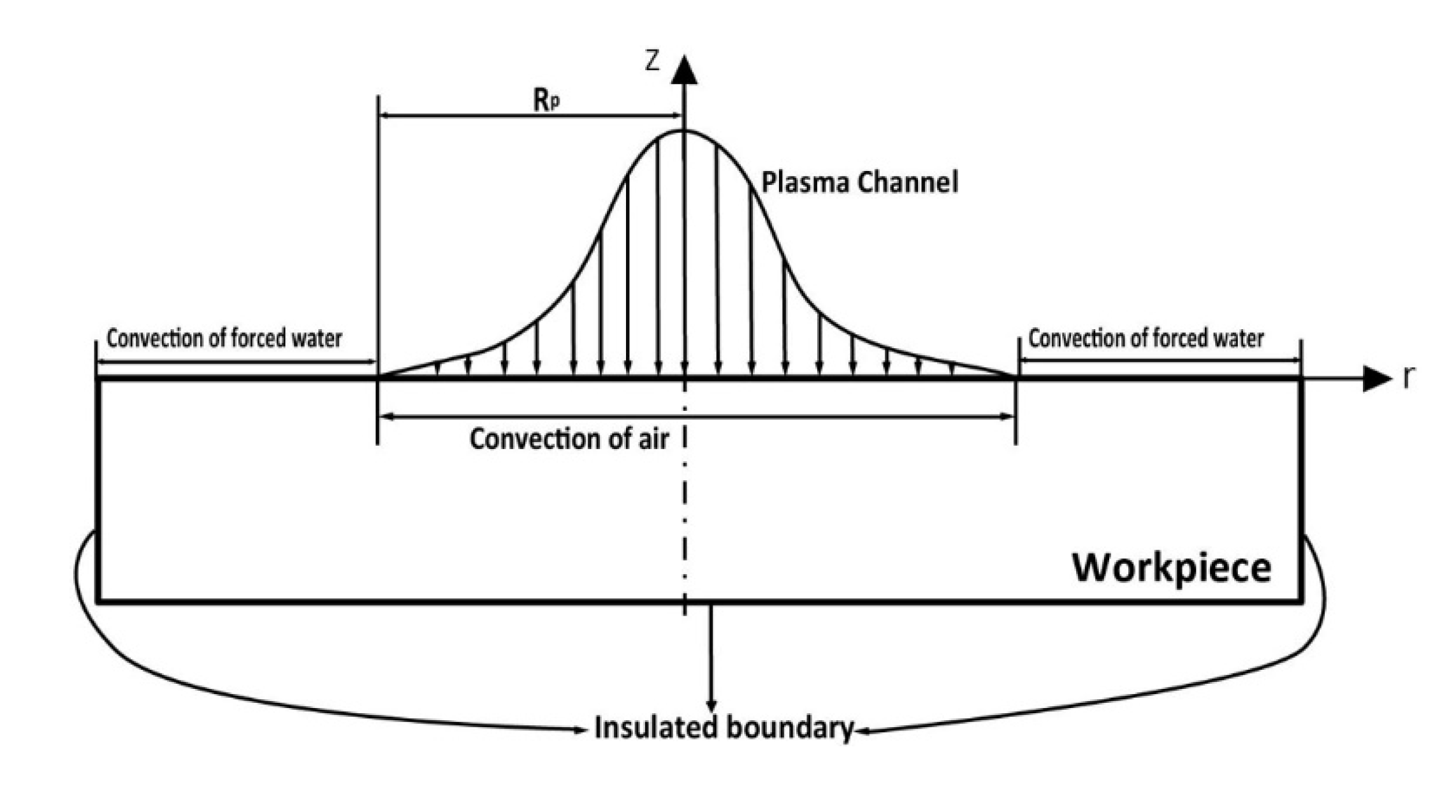
The boundary conditions change over time in the discharge process. First, during the on-time, heat is transferred through the plasma channel. Equation (5) expresses this part of the problem mathematically. As presented in the work of Kitamura et al. [18], although the entire machining process is carried out in a tank filled with dielectric water, the gap between wire and workpiece is almost completely occupied by air bubbles. Therefore, air convection will be used in the simulation of the internal part of plasma channel during pulse on time. For the remaining part that is outside of the plasma channel, the convection of forced deionized water is used. Furthermore, the off-time is as much as 5 times longer than the on-time in this phase, with convection of forced deionized water acting on the entire modeling area. As described in the assumptions presented previously, the influence of heat loss due to radiation can be ignored. Equation (6) expresses heat transfer by convection, where Kt is the thermal conductivity, h is the convection transfer coefficient (which depends on the described boundary conditions) and T0 is the initial temperature.
Moreover, it is necessary to take into account the properties of the material. Given that an extremely high number of discharges are produced in the WEDM process, the maximum temperature must be higher than the melting point of the metal to achieve the objective of material removal. Chen et al. [14] pointed out that the latent heat in the change of state from solid to liquid should not be ignored. Based on this suggestion, the equivalent specific heat of the material is optimized in this work by means of Equation (7). In this equation, Cp and Cmelting are, respectively, the equivalent specific heat capacity when the material is in a solid and liquid state. Tmelting is the melting point, Tref is the ambient reference temperature, and Lmelting is the latent heat in the process of fusion.
As discussed previously, the thermal properties of AISI D2 are listed in Table 5. In addition, the values of Rp and fc that can be found in the literature correspond to experiments carried out under conditions that are very different to those that exist in the working gap in WEDM. The specific resistance of deionized water is 15 to 50 µS/cm (when cutting steel), while this value for EDM oil is approximately 1400 µS/cm. Further, current WEDM commercial machines use very short on-times (approximately 2 μs) when compared to those used in sinking electrical discharge machining. Therefore, the first objective is to obtain feasible values of Rp and fc for the WEDM process, and to study the influence of part surface roughness on these values.
3. Results and Discussion
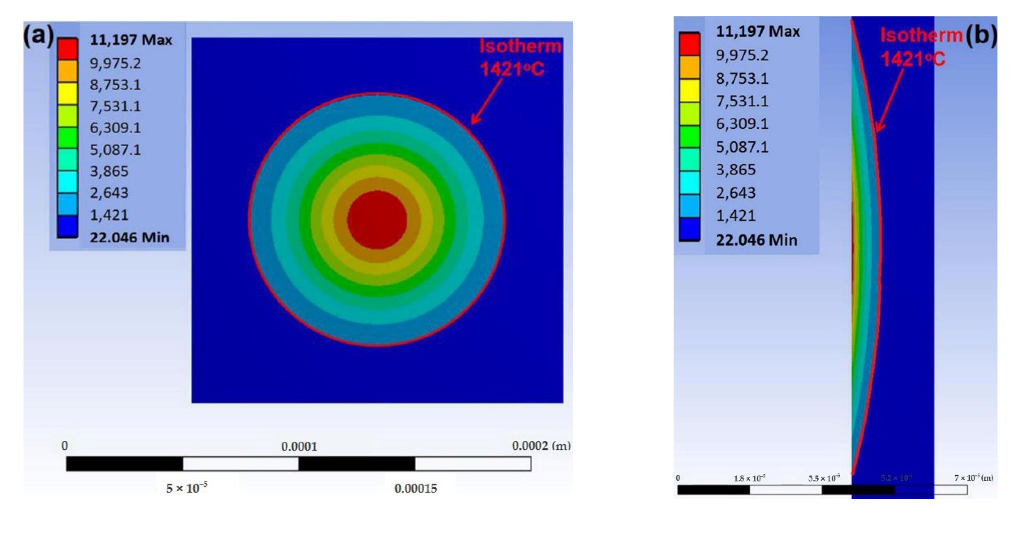
For studying the evolution of the radius of the plasma channel, a time-dependent expression was employed, based on Equation (4), except that the value of channel expansion after 2 μs was varied. Values of Rp after 2 μs from 60 μm to 110 μm were used in the simulations. In the case of heat partition to the workpiece, simulations were run using values from 40% to 90%. Flushing efficiency must be considered, given the fact that not all of the material melted by the discharge is removed and some of debris can be resolided on the surface of workpiece to form a recast layer. Therefore, in the calculation of removal capacity, the volume of the part of the recast layer needs to be subtracted. In this work, a flushing efficiency coefficient of 93% [12] (based on measurements of recast layer for similar working conditions), is used for the following simulation. By applying this coefficient, it was found that the equivalent removal isotherm is 1421 °C (Figure 7). Finally, Table 6 displays the results from the simulations in terms of crater dimensions (volume, diameter and depth) using the numerical model.
To obtain the continuous simulation result and to avoid lengthy simulations, the relations between crater dimensions and volume vs. Rp and fc have been converted into explicit equations using polynomial fitting with Matlab (Version 2019b, MathWorks, Natick, Massachusetts, MA, USA). In order to find the optimum values of Rp and fc that minimize the deviation between numerical simulations and single discharge experiments, an error function accounting for the volume and radius of crater has been proposed (Equation (8)). In this function, vsim is the simulated crater volume and vc is the real crater volume; rsim is the simulated crater radius and rc is the real crater radius. As the limitation of mesh grid of 2 µm, the change of crater depth cannot be showed precisely in the simulation result. Therefore, its weight of verification is further below than vc and rc. However, it also can be later used for checking the accuracy of the results. By establishing the minimum value of error, the optimum value of both Rp and fc can be obtained. The results are shown in Table 7.
The results can be verified by checking the agreement in terms of crater depth. In Table 8, dsim is the simulated crater depth and dc is the real crater depth. According to the obtained results for fc and Rp, the deviations in crater depth are always below 1 μm.
From the comparison above, it appears that experiments conducted on surfaces of lower roughness yield results that are compatible with the notion of an increase in heat partition ratio to the workpiece. With a single discharge on a rough surface, a good agreement between experiments and simulation is found for the combination Rp = 102.66 μm and fc = 58.94%. When discharging on a trim surface, the optimum values of both Rp and fc increase up to 110 μm and 65.91%, respectively. The effect is confirmed when discharging on a smoother flat surface: in this case, the optimum value of fc becomes as high as 85.44% and the plasma channel decreases to 81.43 μm. Therefore, it can be concluded that the surface on which discharge occurs has an influence on the heat partition ratio to the workpiece. In addition, with a change from a rough surface to a trim surface or flat surface, the plasma channel radius increases to 25.97% and 20.68%, respectively.
4. Conclusions
This work represents the first attempt to study the influence of part surface roughness on the heat conduction mechanisms in WEDM. It can help us to further understand the detail of removal principle in no matter roughing cut and trim cut. In the experiments, the anode of AISI D2 and cathode of brass are adopted. On the basis of the results obtained, the following conclusions can be drawn.
1. Single discharge experiments were conducted on samples with different surface topographies, characterized by different values of Ra and Rt. With the increase of Ra from 0.46 μm to 2.60 μm and Rt from 3.59 μm to 15.27 μm, the crater radius decreases by approximately 8.1%. Moreover, the decreases of depth and volume are more marked, falling to 37.7% and 40.4%, respectively.
2. A Finite Element thermal model was applied in order to run simulations with different values of both variables (fc and Rp). Through inverse fitting between experimental and numerical results, optimal values of heat partition and plasma channel radius can be obtained. In the case of flat surface, fc is 85.44% and Rp is 81.43 μm. On a trim surface, fc is 65.91% and Rp is 110.00 μm. Finally, on a rough surface fc is 58.94% and Rp is 102.66 μm.
3. With regard to the plasma channel radius, smaller values were obtained for the smoothest part surface, and the resulting values are in agreement with existing values in the literature (approximately 80 μm). When increasing the part surface roughness, the value of the radius can increase up to approximately 25.97%. Correlating with the observed real crater radius and volume, it can be known that with the increasing of plasma channel radius, the heat source goes into the workpiece more dispersed. In the case of rougher surface, although the there is more area that affected by the heat source, finally the temperature of most area cannot reach to the melting point and it causes the smaller crater radius and volume, while the metal removal rate decreases.
4. A strong correlation was observed between an increase of heat partition ratio and a decrease in part surface roughness. For the roughest surface, a value of 58.94% was obtained for the heat partition to the workpiece. This value increases sharply to 85.44% when discharging on the smoothest surface. This trend was confirmed by the results obtained when discharging on a surface of intermediate topography (65.91%).
5. The parameters obtained from inverse fitting were then validated by conducting a comparison between the experimental and numerical values of crater diameter. For the three cases of surface roughness studied, the results show deviations below 1 μm, thus confirming the validity of the approach. These results contribute towards a more complete understanding of the influence of surface roughness to the spark occurring.
Author Contributions
Conceptualization, J.W. and J.A.S.; methodology, J.W., J.A.S., and B.I.; software, J.W.; validation, J.W.; formal analysis, J.W. and J.A.S.; investigation, J.W. and J.A.S.; resources, J.A.S, B.I., and I.A.; data curation, J.W.; writing—original draft preparation, J.W.; writing—review and editing, J.A.S.; visualization, J.A.S.; supervision, J.A.S. and B.I.; project administration, I.A.; funding acquisition, J.A.S. and B.I. All authors have read and agreed to the published version of the manuscript.
Funding
This research was funded by the Spanish Ministry of Economy and Competitiveness and the European Regional Development Fund (ERDF) operation program for funding the project “Scientific models and machine-tool advanced sensing techniques for efficient machining of precision components of Low-Pressure Turbines” (DPI2017-82239-P).
Conflicts of Interest
The authors declare no conflict of interest.
Abbreviations
The following abbreviations are used in this manuscript.
| C | Specific heat (J/(kg·°C)) |
| dc | Crater depth (µm) |
| dsim | Simulation depth of Crater (µm) |
| f | Wire infeed rate (mm/min) |
| fc | Fraction of total heat transferred to workpiece (%) |
| FEM | Finite element method |
| I | Pulse Current (A) |
| r | Distance to the center of heat source (µm) |
| Ra | Roughness Average (µm) |
| rc | Crater radius (µm) |
| rsim | Simulation radius of crater (µm) |
| Rp | Plasma channel radius (µm) |
| Rt | Total height of the roughness profile (µm) |
| ton | Pulse duration (µs) |
| toff | Pulse off time (µs) |
| T | Temperature (°C) |
| t | Time (µs) |
| U | Voltage (V) |
| Us | Servo voltage (V) |
| vc | Crater volume (µm3) |
| vsim | Simulation volume of crater (µm3) |
| WEDM | Wire Electrical Discharge Machining |
References
- Volosova, M.A.; Okunkova, A.A.; Fedorov, S.V.; Hamdy, K.; Mikhailova, M.A. Electrical discharge machining non-conductive ceramics: Combination of materials. Technologies 2020, 8, 32. [Google Scholar] [CrossRef]
- Kunieda, M.; Lauwers, B.; Rajurkar, K.P.; Schumacher, B.M. Advancing EDM through fundamental insight into the process. CIRP Ann. 2005, 54, 64–87. [Google Scholar] [CrossRef]
- Radhakrishnan, P.; Vijayaraghavan, L.; Ramesh, B.N. Assessment of material removal capability with vibration-assisted wire electrical discharge machining. J. Manuf. Process. 2017, 26, 323–329. [Google Scholar]
- Chu, X.; Zeng, X.; Zhuang, W.; Zhou, W.; Quan, X.; Fu, T. Vibration assisted high-speed wire electric discharge machining for machining surface microgrooves. J. Manuf. Process. 2019, 44, 418–426. [Google Scholar]
- Sánchez, J.A.; Conde, A.; Arriandiaga, A.; Wang, J.; Plaza, S. Unexpected event prediction in wire electrical discharge machining using deep learning techniques. Materials 2018, 11, 1100. [Google Scholar] [CrossRef] [PubMed] [Green Version]
- Thankachan, T.; Prakash, K.S.; Malini, R.; Ramu, S.; Sundararaj, P.; Rajandran, S.; Rammasamy, D.; Jothi, S. Prediction of surface roughness and material removal rate in wire electrical discharge machining on aluminum based alloys/composites using Taguchi coupled Grey Relational Analysis and Artificial Neural Networks. Appl. Surf. Sci. 2019, 472, 22–35. [Google Scholar] [CrossRef] [Green Version]
- Izquierdo, B.; Sánchez, J.A.; Plaza, S.; Pombo, I.; Ortega, N. A numerical model of the EDM process considering the effect of multiple discharges. Int. J. Mach. Tools Manuf. 2009, 49, 220–229. [Google Scholar] [CrossRef]
- Zhang, G.; Huang, H.; Zhang, Z.; Zhang, Y. Study on the effect of three dimensional wire vibration on WEDM based on a novel thermophysical model. Int. J. Adv. Manuf. Technol. 2019, 100, 2089–2101. [Google Scholar]
- Spur, G.; Schönbeck, J. Anode Erosion in Wire-EDM-A Theoretical Model. CIRP Ann. 1993, 42, 253–256. [Google Scholar] [CrossRef]
- Kavimani, V.; Prakash, K.S.; Thankachan, T. Multi-objective optimization in WEDM process of graphene-SiC-magnesium composite through hybrid techniques. Measurement 2019, 145, 335–349. [Google Scholar] [CrossRef]
- Mouralova, K.; Zahradnicek, R.; Benes, L.; Prokes, T.; Hrdy, R.; Fries, J. Study of micro structural material changes after WEDM based on TEM lamella analysis. Metals 2020, 10, 949. [Google Scholar] [CrossRef]
- Wang, J.; Sanchez, J.A.; Izquierdo, B.; Ayesta, I. Experimental and numerical study of crater volume in wire electrical discharge machining. Materials 2020, 13, 577. [Google Scholar] [CrossRef] [PubMed] [Green Version]
- Pandit, S.M.; Rajurkar, K.P.; Shaw, M.C. Data Dependent systems approach to EDM process modeling from surface roughness profiles. CIRP Ann. 1980, 29, 107–112. [Google Scholar] [CrossRef]
- Chen, Z.; Zhang, G.; Han, F.; Zhang, Y.; Rang, Y. Determination of the optimal servo feed speed by thermal model during multi-pulse discharge process of WEDM. Int. J. Mech. Sci. 2018, 142, 359–369. [Google Scholar] [CrossRef]
- Joshi, S.N.; Pande, S.S. Development of an intelligent process model for EDM. Int. J. Adv. Manuf. Technol. 2009, 45, 300–317. [Google Scholar]
- Das, S.; Joshi, S.S. Modeling of spark erosion rate in microwire-EDM. Int. J. Adv. Manuf. Technol. 2010, 48, 581–596. [Google Scholar] [CrossRef]
- Patel, M.R.; Barrufet, M.A.; Eubank, P.T.; DiBitonto, D.D. Theoretical models of the electrical discharge machining process. II. The anode erosion model. J. Appl. Phys. 1989, 66, 4104–4111. [Google Scholar] [CrossRef]
- Kitamura, T.; Kunieda, M.; Abe, K. Observation of relationship between bubbles and discharge locations in EDM using transparent electrodes. Precis. Eng. 2015, 40, 26–32. [Google Scholar] [CrossRef]
Figure 1.
Wire Electrical Discharge Machining (WEDM) working principle.

Figure 2.
Heat transfer of plasma channel.

Figure 3.
Top view of the adjustments for tracking the first craters that appear on the surface.

Figure 4.
Craters on different surface: (a) Craters on a flat surface; (b) Craters on a trim surface; (c) Craters on a rough surface.
Figure 4.
Craters on different surface: (a) Craters on a flat surface; (b) Craters on a trim surface; (c) Craters on a rough surface.

Figure 5.
(a) Crater topography following a single-discharge experiment on a flat surface; (b) Determination of crater contour with ImageJ; (c) Measurement of crater depth.
Figure 5.
(a) Crater topography following a single-discharge experiment on a flat surface; (b) Determination of crater contour with ImageJ; (c) Measurement of crater depth.

Figure 6.
Heat transfer to workpiece.

Figure 7.
One of the simulation results of the thermal modeling of the crater: (a) Front view and (b) lateral view.
Figure 7.
One of the simulation results of the thermal modeling of the crater: (a) Front view and (b) lateral view.


Table 1.
AISI D2 tool steel chemical composition.
| Element | Weight (%) |
|---|---|
| C | 1.55 |
| Si | 0.3 |
| Mn | 0.4 |
| Mo | 0.8 |
| Cr | 11.8 |
| V | 0.8 |
Table 2.
WEDM parameters for preparing the surface.
| WEDM Parameters | Rough Cut | 1st Trim Cut | 2nd Trim Cut |
|---|---|---|---|
| I (A) | 5 | 5 | 3 |
| U (V) | 80 | 100 | 90 |
| Us (V) | 52 | 48 | 10 |
| f (mm/min) | 12 | 10 | 10 |
| ton (μs) | 2 | 2 | 2 |
| toff (μs) | 12 | 9 | 1 |
| Dielectric | Deionized water | ||
Table 3.
Surface roughness following different processes.
| Flat Surface | Trim Surface | Rough Surface |
|---|---|---|
| Ra (μm): 0.46 | Ra (μm): 0.81 | Ra (μm): 2.60 |
| Rt (μm): 3.59 | Rt (μm): 5.92 | Rt (μm): 15.27 |
Table 4.
Descriptive statistics of a crater produced by single discharge experiments on parts of varying roughness.
Table 4.
Descriptive statistics of a crater produced by single discharge experiments on parts of varying roughness.
| Surface | Ra (μm) | Rt (μm) | rc (μm) | dc (μm) | vc (μm3) | ||
|---|---|---|---|---|---|---|---|
| Average | STD | Average | STD | Average | |||
| Flat surface | 0.46 | 3.59 | 53.0 | 16.2 | 7.7 | 1.3 | 35,648.49 |
| Trim surface | 0.81 | 5.92 | 52.85 | 27.7 | 4.8 | 0.7 | 23,168.42 |
| Rough surface | 2.60 | 15.27 | 48.75 | 21.6 | 5.1 | 1.2 | 21,255.18 |
Table 5.
Thermal properties of AISI D2 tool steel.
| Density (kg/m3) | Thermal Conductivity (W/m·°C) | Melting Point (°C) | Specific Heat (J/kg·°C) | |
|---|---|---|---|---|
| at 20 °C | at 1421 °C | |||
| 7700 | 20 | 1421 | 460 | 730 |
Table 6.
Crater dimensions from numerical simulation of different combinations of heat partition to the workpiece (fc) and radius of the plasma channel after 2 μs.
Table 6.
Crater dimensions from numerical simulation of different combinations of heat partition to the workpiece (fc) and radius of the plasma channel after 2 μs.
| Rp (After 2 μs) | Crater | fc (%) | |||||
|---|---|---|---|---|---|---|---|
| 40% | 50% | 60% | 70% | 80% | 90% | ||
| 60 μm | vsim (μm3) | 16,910.59 | 20,798.83 | 24,550.84 | 27,910.57 | 30,814.83 | 33,526.78 |
| rsim (μm) | 38 | 40 | 42 | 44 | 44 | 46 | |
| dsim (μm) | 6 | 8 | 8 | 8 | 8 | 10 | |
| 70 μm | vsim (μm3) | 16,414.99 | 20,983.64 | 25,079.94 | 29,055.76 | 32,950.84 | 36,199.14 |
| rsim (μm) | 40 | 42 | 44 | 46 | 48 | 50 | |
| dsim (μm) | 6 | 6 | 6 | 6 | 8 | 8 | |
| 80 μm | vsim (μm3) | 14,975.55 | 20,192.55 | 25,327.77 | 29,567.07 | 33,366.77 | 37,454.72 |
| rsim (μm) | 40 | 44 | 48 | 50 | 52 | 52 | |
| dsim (μm) | 4 | 6 | 6 | 6 | 6 | 8 | |
| 90 μm | vsim (μm3) | 13,495.76 | 18,528.32 | 23,815.98 | 29,222.14 | 33,766.65 | 37,854.46 |
| rsim (μm) | 40 | 46 | 48 | 53 | 54 | 56 | |
| dsim (μm) | 4 | 4 | 6 | 6 | 6 | 6 | |
| 100 μm | vsim (μm3) | 10,663.54 | 16,992.50 | 22,239.65 | 27,029.98 | 32,942.26 | 37,791.04 |
| rsim (μm) | 40 | 46 | 50 | 52 | 56 | 58 | |
| dsim (μm) | 4 | 4 | 4 | 6 | 6 | 6 | |
| 110 μm | vsim (μm3) | 8351.63 | 14,200.44 | 20,383.55 | 25,638.57 | 30,221.82 | 36,071.15 |
| rsim (μm) | 36 | 44 | 50 | 54 | 56 | 60 | |
| dsim (μm) | 2 | 4 | 4 | 4 | 4 | 6 | |
Table 7.
Optimum values of Rp and fc as obtained by minimizing error for workpieces of varying roughness.
Table 7.
Optimum values of Rp and fc as obtained by minimizing error for workpieces of varying roughness.
| Surface | Optimum Values | Error (%) | |
|---|---|---|---|
| fc (%) | Rp (μm) | ||
| Flat surface | 85.44 | 81.43 | 0.004 |
| Trim surface | 65.91 | 110.00 | 2.594 |
| Rough surface | 58.94 | 102.66 | 0.01 |
Table 8.
Validation of results in terms of crater depth.
| Surface | dc (μm) | dsim (μm) |
|---|---|---|
| Flat surface | 7.7 | 7.02 |
| Trim surface | 4.8 | 4.23 |
| Rough surface | 5.1 | 4.23 |
© 2020 by the authors. Licensee MDPI, Basel, Switzerland. This article is an open access article distributed under the terms and conditions of the Creative Commons Attribution (CC BY) license (http://creativecommons.org/licenses/by/4.0/).
Share and Cite
MDPI and ACS Style
Wang, J.; Sánchez, J.A.; Izquierdo, B.; Ayesta, I. Influence of AISI D2 Workpiece Roughness on Heat Partition and Plasma Channel Radius in the WEDM Process. Metals 2020, 10, 1360. https://doi.org/10.3390/met10101360
AMA Style
Wang J, Sánchez JA, Izquierdo B, Ayesta I. Influence of AISI D2 Workpiece Roughness on Heat Partition and Plasma Channel Radius in the WEDM Process. Metals. 2020; 10(10):1360. https://doi.org/10.3390/met10101360
Chicago/Turabian StyleWang, Jun, Jose Antonio Sánchez, Borja Izquierdo, and Izaro Ayesta. 2020. "Influence of AISI D2 Workpiece Roughness on Heat Partition and Plasma Channel Radius in the WEDM Process" Metals 10, no. 10: 1360. https://doi.org/10.3390/met10101360
Note that from the first issue of 2016, this journal uses article numbers instead of page numbers. See further details here.