Production-Related Surface and Subsurface Properties and Fatigue Life of Hybrid Roller Bearing Components


 , and
, and
Abstract
:1. Introduction
- Can the surface and subsurface properties be adjusted to a similar extent as for conventional components by varying the cutting parameters?
- Do the components have the same operating behavior with regard to friction or deflection due to an alternating shear force?
- Do the same damage mechanisms occur regarding rolling contact fatigue and possible structural failure?
- Even if the joining zone is not directly loaded in the later application, is it still the weakest point in the component?
2. Materials and Methods
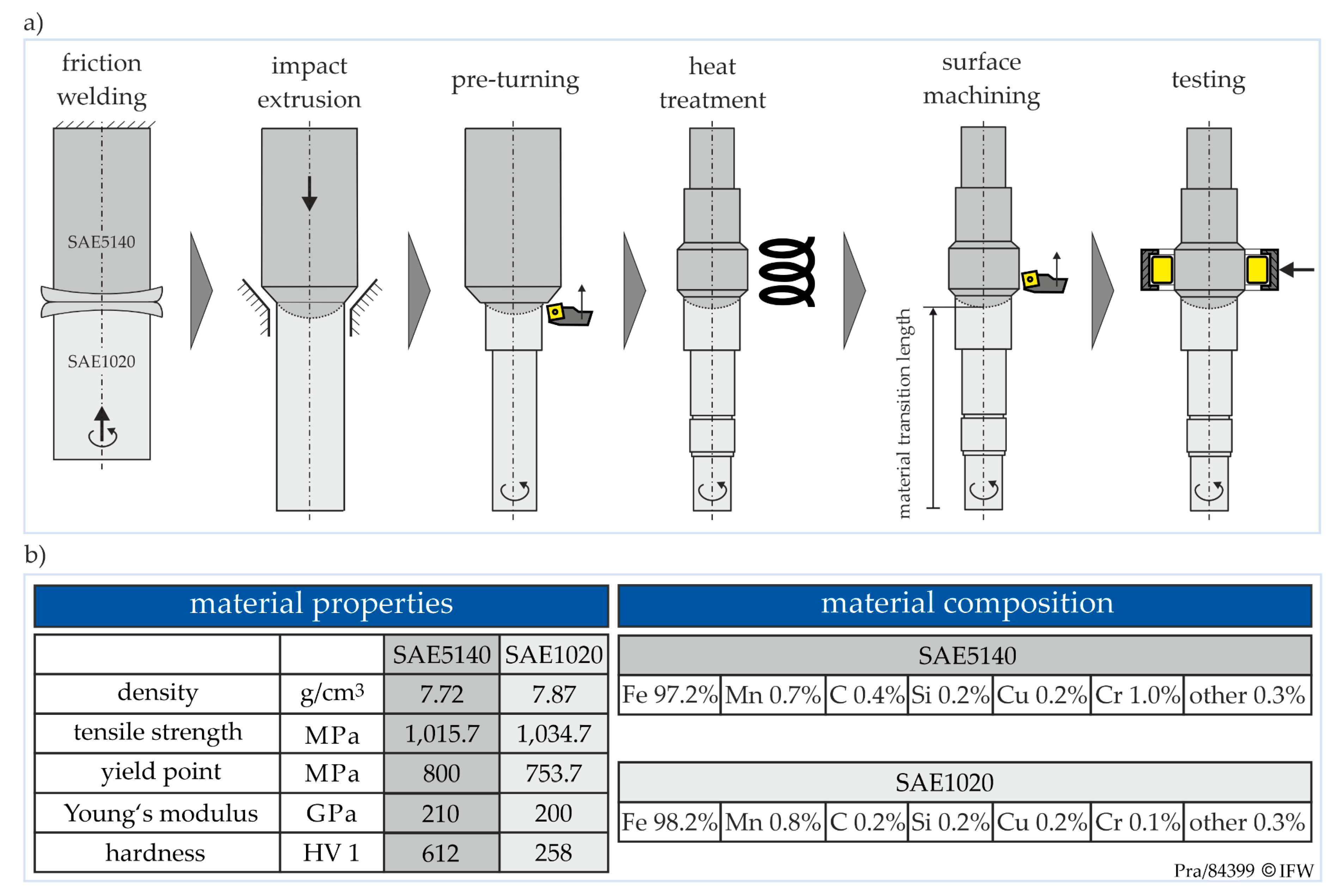
2.1. Materials
2.2. Machining
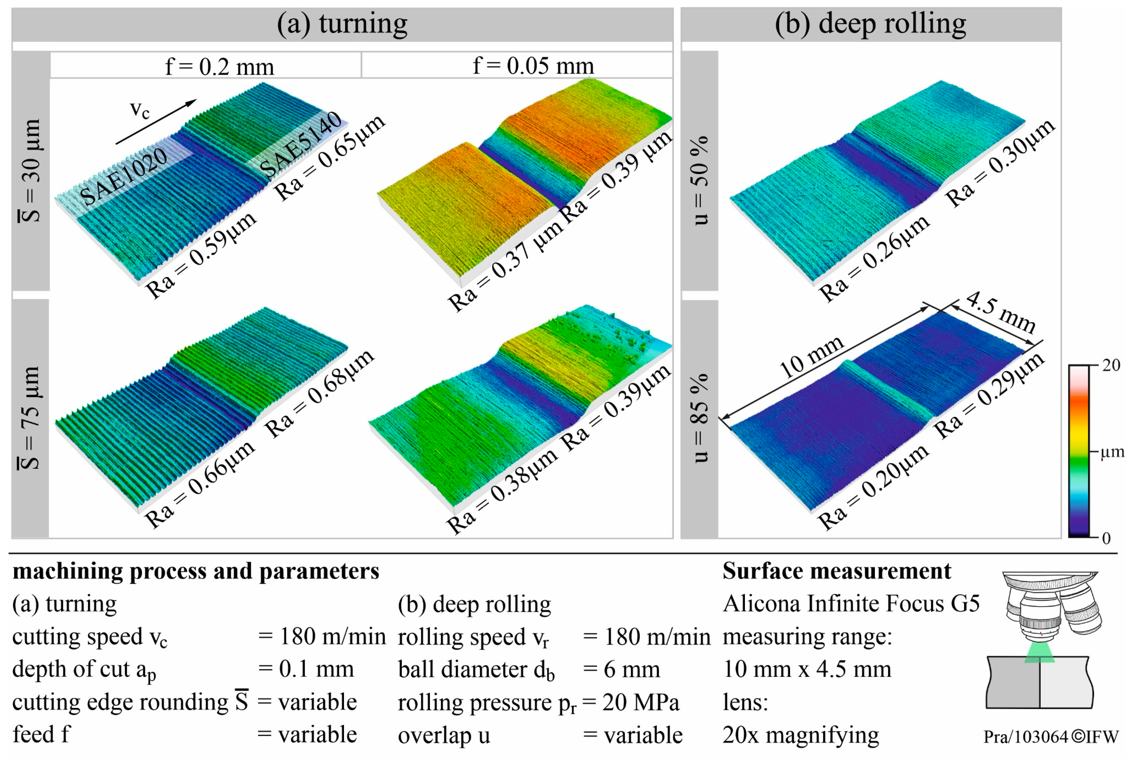
2.2.1. Turning
2.2.2. Deep Rolling
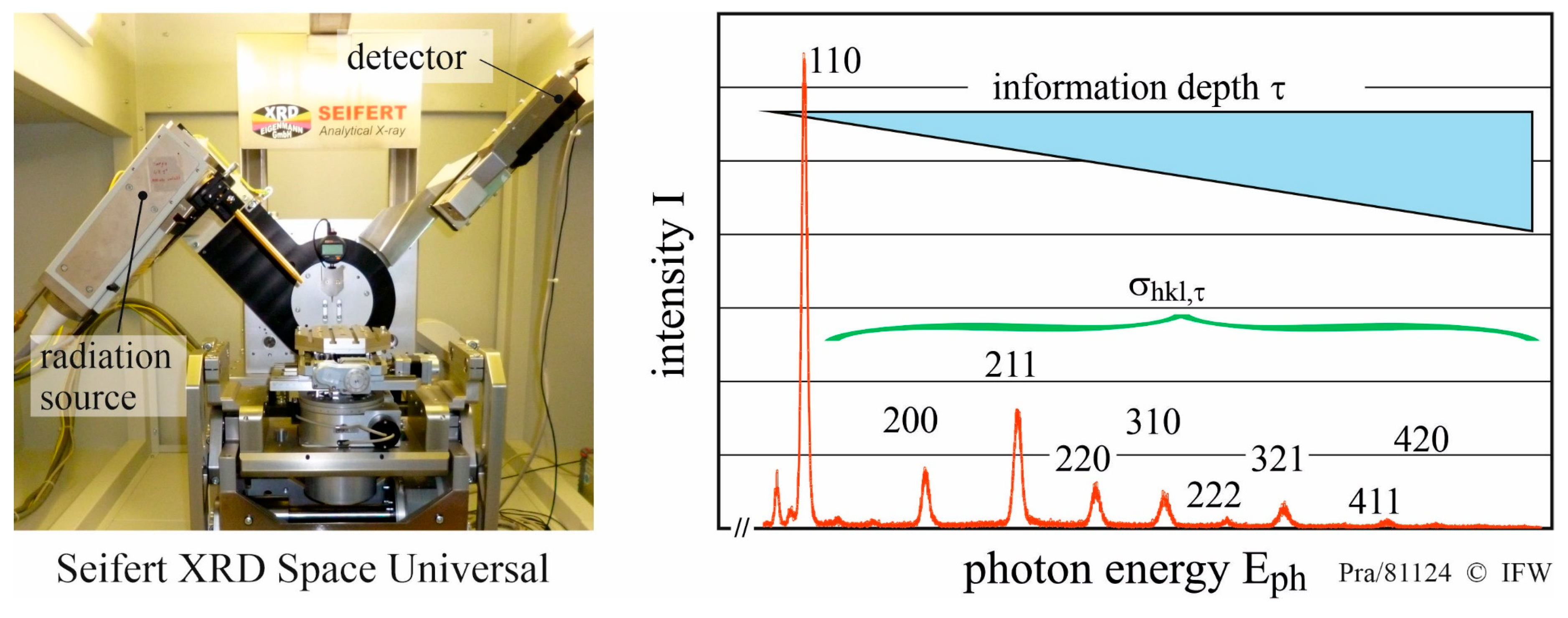
2.3. Residual Stress Measurement
2.4. Fatigue Life Testing
3. Results and Discussion
3.1. Surface Measurement
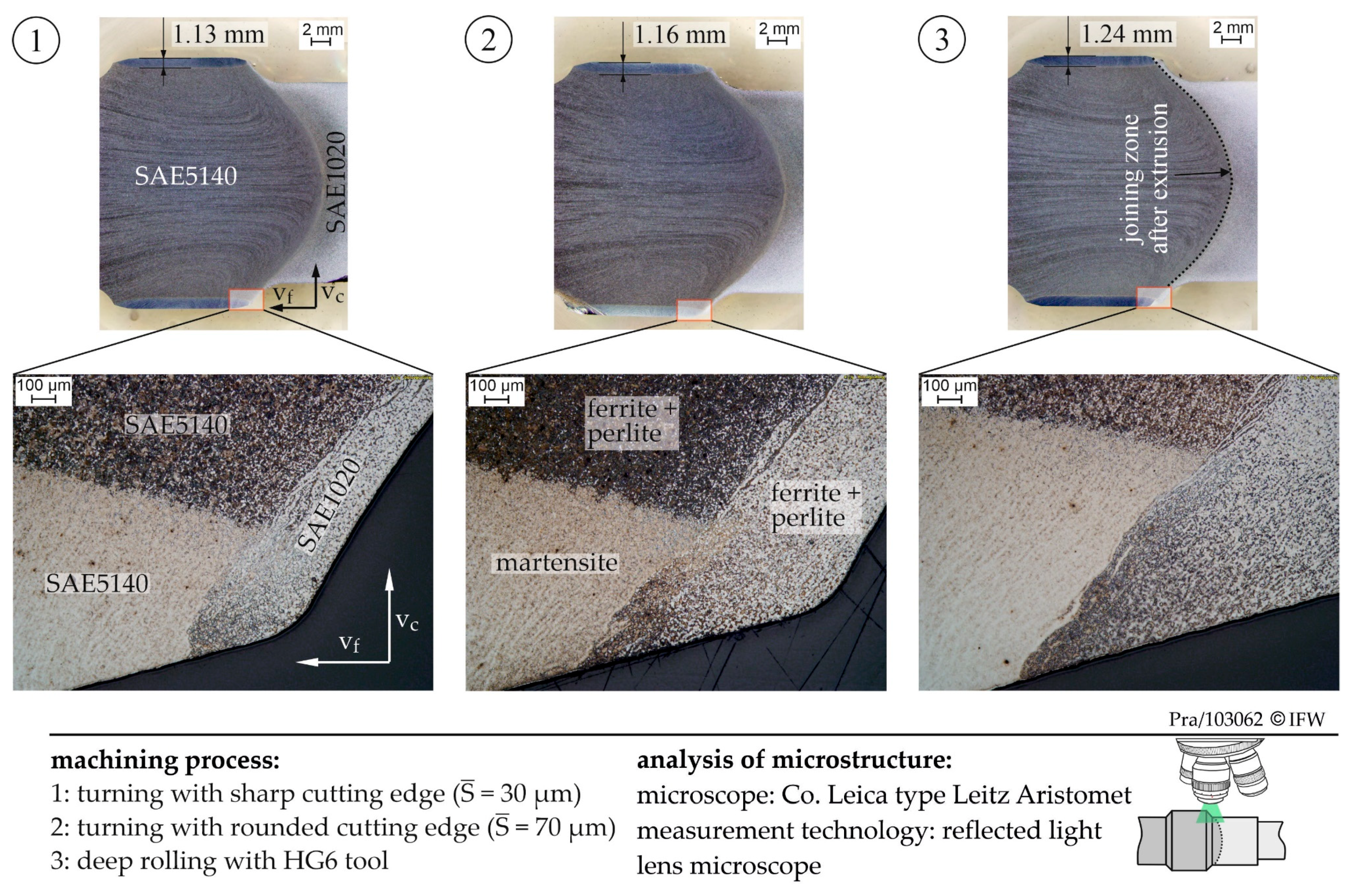
3.2. Microstructure and Hardness
3.3. Residual Stresses
3.4. Fatigue Life
3.5. Damage Analysis
4. Conclusions and Outlook
Author Contributions
Funding
Acknowledgments
Conflicts of Interest
References
- Giampieri, A.; Ling-Chin, J.; Ma, Z.; Smallbone, A.; Roskilly, A. A review of the current automotive manufacturing practice from an energy perspective. Appl. Energy 2020, 261, 114074. [Google Scholar] [CrossRef]
- Huang, J.; Chang, Q.; Arinez, J.; Xiao, G. A Maintenance and Energy Saving Joint Control Scheme for Sustainable Manufacturing Systems. Procedia CIRP 2019, 80, 263–268. [Google Scholar] [CrossRef]
- Schmidt, M.; Bauer, J.; Haubach, C. Ressourceneffiziente Herstellung mechanischer Verbindungselemente. In 100 Betriebe für Ressourceneffizienz-Band 1; Springer Spektrum: Berlin/Heidelberg, Germany, 2017; pp. 138–141. [Google Scholar] [CrossRef]
- Immarigeon, J.-P.; Holt, R.; Koul, A.; Zhao, L.; Wallace, W.; Beddoes, J. Lightweight materials for aircraft applications. Mater. Charact. 1995, 35, 41–67. [Google Scholar] [CrossRef]
- Sköck-Hartmann, B.; Gries, T. Automotive applications of non-crimp fabric composites. Non-Crimp Fabr. Compos. 2011, 461–480. [Google Scholar] [CrossRef]
- Jurczak, P.; Witkowska, J.; Rodziewicz-Motowidlo, S.; Lach, S. Proteins, peptides and peptidomimetics as active agents in implant surface functionalization. Adv. Colloid Interface Sci. 2020, 276, 102083. [Google Scholar] [CrossRef]
- Cole, G.; Sherman, A. Light weight materials for automotive applications. Mater. Charact. 1995, 35, 3–9. [Google Scholar] [CrossRef]
- Padmanabhan, R.; Oliveira, M.C.; Menezes, L.F. Tailor Welded Blanks for Advanced Manufacturing; Woodhead Publishing Series in Welding and Other Joining Technologies; Woodhead Publishing Limited: Cambridge, UK, 2011; pp. 97–117. [Google Scholar] [CrossRef]
- Fiebig, S.; Sellschopp, J.; Manz, H.; Vietor, T.; Axmann, K.; Schumacher, A. Future challenges for topology optimization for the usage in automotive lightweight design technologies. In Proceedings of the 11th World Congress on Structural and Multidisciplinary Optimization, Sydney, Australia, 7–12 June 2015. [Google Scholar]
- Behrens, B.-A.; Bouguecha, A.; Frischkorn, C.; Huskic, A.; Stakhieva, A.; Duran, D. Tailored forming technology for three dimensional components: Approaches to heating and forming. In Proceedings of the 5th Conference on Thermomechanical Processing, Milan, Italy, 26–28 October 2016. [Google Scholar]
- Jawahir, I.S.; Brinksmeier, E.; M’Saoubi, R.; Aspinwall, D.; Outeiro, J.; Meyer, D.; Umbrello, D.; Jayal, A.D. Surface integrity in material removal processes: Recent advances. CIRP Ann. 2011, 60, 603–626. [Google Scholar] [CrossRef]
- Nélias, D.; Dumont, M.L.; Champiot, F.; Vincent, A.; Girodin, D.; Fougéres, R.; Flamand, L. Role of Inclusions, Surface Roughness and Operating Conditions on Rolling Contact Fatigue. J. Tribol. 1999, 121, 240–251. [Google Scholar] [CrossRef]
- Olver, A.V. The Mechanism of Rolling Contact Fatigue: An Update. Proc. Inst. Mech. Eng. Part J J. Eng. Tribol. 2005, 219, 313–330. [Google Scholar] [CrossRef]
- Sadeghi, F.; Jalalahmadi, B.; Slack, T.; Raje, N.; Arakere, N.K. A Review of Rolling Contact Fatigue. J. Tribol. 2009, 131, 041403. [Google Scholar] [CrossRef]
- Harris, T.; Kotzalas, M. Rolling Bearing Analysis, 5th ed.; CRC Press: Boca Raton, FL, USA, 2006. [Google Scholar] [CrossRef]
- Novovic, D.; Dewes, R.; Aspinwall, D.; Voice, W.; Bowen, P. The effect of machined topography and integrity on fatigue life. Int. J. Mach. Tools Manuf. 2004, 44, 125–134. [Google Scholar] [CrossRef]
- Brinksmeier, E.; Cammett, J.; König, W.; Leskovar, P.; Peters, J.; Tönshoff, H. Residual Stresses—Measurement and Causes in Machining Processes. CIRP Ann. 1982, 31, 491–510. [Google Scholar] [CrossRef]
- Sollich, A. Verbesserung des Dauerschwingverhaltens hochfester Stähle durch gezielte Eigenspannungserzeugung, Fortschrittsberichte VDI; VDI Verlag: Düsseldorf, Germany, 1994; Volume 5, p. 376. [Google Scholar]
- Creţu, S.; Popinceanu, N. The influence of residual stresses induced by plastic deformation on rolling contact fatigue. Wear 1985, 105, 153–170. [Google Scholar] [CrossRef]
- Matsumoto, Y.; Hashimoto, F.; Lahoti, G. Surface Integrity Generated by Precision Hard Turning. CIRP Ann. 1999, 48, 59–62. [Google Scholar] [CrossRef]
- Schwach, D.; Guo, Y.B. A fundamental study on the impact of surface integrity by hard turning on rolling contact fatigue. Int. J. Fatigue 2006, 28, 1838–1844. [Google Scholar] [CrossRef]
- Guo, Y.B.; Warren, A.; Hashimoto, F. The basic relationships between residual stress, white layer, and fatigue life of hard turned and ground surfaces in rolling contact. CIRP J. Manuf. Sci. Technol. 2010, 2, 129–134. [Google Scholar] [CrossRef]
- Choi, Y. A study on the effects of machining-induced residual stress on rolling contact fatigue. Int. J. Fatigue 2009, 31, 1517–1523. [Google Scholar] [CrossRef]
- Denkena, B.; Poll, G.; Maiß, O.; Neubauer, T. Affecting the Life Time of Roller Bearings by an Optimal Surface Integrity Design after Hard Turning and Deep Rolling. Adv. Mater. Res. 2014, 966, 425–434. [Google Scholar] [CrossRef]
- Neubauer, T. Betriebs-und Lebensdauerverhalten Hartgedrehter und Festgewalzter Zylinderrollenlager. Ph.D. Thesis, Leibniz University Hannover, Hanover, Germany, 2016. (In German). [Google Scholar]
- Pape, F.; Neubauer, T.; Maiß, O.; Denkena, B.; Poll, G. Influence of Residual Stresses Introduced by Manufacturing Processes on Bearing Endurance Time. Tribol. Lett. 2017, 65, 87. [Google Scholar] [CrossRef]
- Maiß, O. Lebensdauererhöhung von Wälzlagern durch mechanische Bearbeitung. Ph.D. Thesis, Leibniz University Hannover, Hanover, Germany, 2019. (In German). [Google Scholar]
- Pape, F.; Coors, T.; Poll, G. Studies on the Influence of Residual Stresses on the Fatigue Life of Rolling Bearings in Dependence on the Production Processes. Front. Mech. Eng. 2020, 6. [Google Scholar] [CrossRef]
- Breidenstein, B.; Denkena, B.; Meyer, K.; Prasanthan, V. Influence of subsurface properties on the application behavior of hybrid components. Procedia CIRP 2020, 87, 302–308. [Google Scholar] [CrossRef]
- Hsu, T.-K.; Zeren, E. Effects of cutting edge geometry, workpiece hardness, feed rate and cutting speed on surface roughness and forces in finish turning of hardened AISI H13 steel. Int. J. Adv. Manuf. Technol. 2004, 25, 262–269. [Google Scholar] [CrossRef]
- Burhanuddin, Y.; Haron, C.H.C.; Ghani, J.A. The Effect of Tool Edge Geometry on Tool Performance and Surface Integrity in Turning Ti-6Al-4V Alloys. Adv. Mater. Res. 2011, 1211–1221. [Google Scholar] [CrossRef]
- Abrão, A.M.; Denkena, B.; Breidenstein, B.; Mörke, T. Surface and subsurface alterations induced by deep rolling of hardened AISI 1060 steel. Prod. Eng. 2014, 8, 551–558. [Google Scholar] [CrossRef]
- Macherauch, E.; Müller, P. Das sin2ψ--Verfahren der röntgenographischen Spannungsmessung. Zeitschrift für Angewandte Physik 1961, 13, 305–312. [Google Scholar]
- Breidenstein, B.; Denkena, B.; Mörke, T.; Prasanthan, V. Non-Destructive Determination of Residual Stress Depth Profiles of Hybrid Components by Energy Dispersive Residual Stress Measurement. Key Eng. Mater. 2017, 742, 613–620. [Google Scholar] [CrossRef]
- Weibull, W. A Statistical Distribution Function of Wide Applicability. J. Appl. Mech. 1951, 103, 293–297. [Google Scholar]
- Coors, T.; Pape, F.; Poll, G. Bearing Fatigue Life of a Multi-Material Shaft with an Integrated Raceway. Bear. World J. 2019, 3, 23–30. [Google Scholar]
- Zaretsky, E.V.; Branzai, E.V. Rolling Bearing Service Life Based on Probable Cause for Removal—A Tutorial. Tribol. Trans. 2016, 60, 300–312. [Google Scholar] [CrossRef]
- Denkena, B.; De Leon, L.; Bassett, E.; Rehe, M. Cutting Edge Preparation by Means of Abrasive Brushing. Key Eng. Mater. 2010, 438, 1–7. [Google Scholar] [CrossRef]
- Gleß, M. Wälzkontaktermüdung bei Mischreibung. Ph.D. Thesis, Otto-von-Guericke-Universität Magdeburg, Magdeburg, Germany, 2009. (In German). [Google Scholar]


| Process Parameters | Unit | Analogy Experiments | Final Component |
|---|---|---|---|
| cutting speed, vc | (m/min) | 50–200 | 180 |
| feed, f | (mm) | 0.05–0.2 | 0.05 |
| depth of cut, ap | (mm) | 0.1 | 0.1 |
| cutting-edge geometry, Sα/Sγ | (µm) | 30/30 and 75/75 | 30/30 and 75/75 |
| cutting direction, | (-) | SAE1020→SAE5140 | SAE1020→SAE5140 |
| Process Parameters | Unit | Analogy Experiments | Final Component |
|---|---|---|---|
| deep rolling speed, vw | (m/min) | 180 | 180 |
| overlap, u | (%) | 50–99 | 85 |
| deep rolling pressure, pr | (bar) | 400 | 400 |
| ball diameter, db | (mm) | 6.35 | 6.35 |
| deep rolling direction | (-) | SAE1020→SAE5140 | SAE1020→SAE5140 |
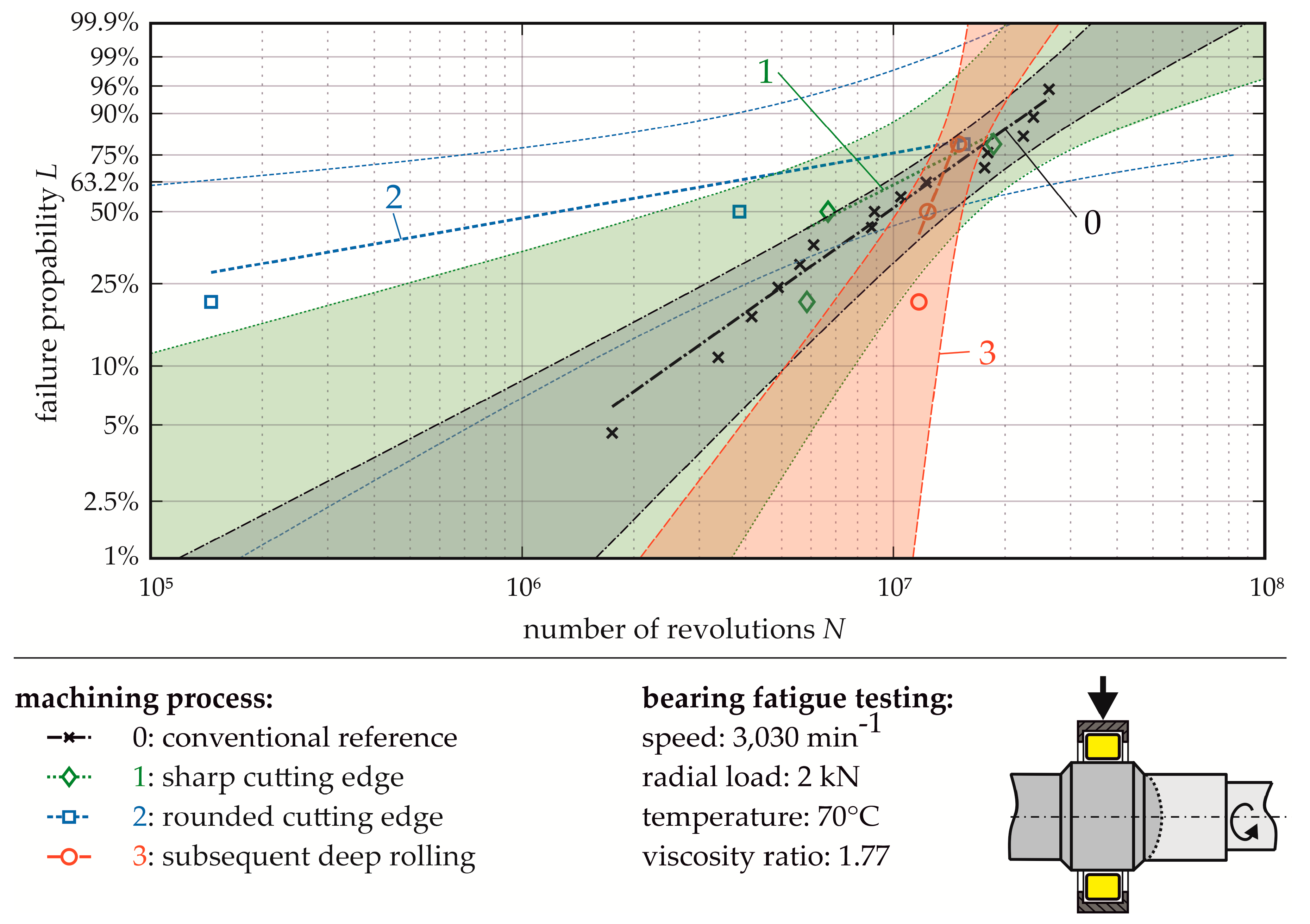
| Weibull Parameter | Unit | 0: Monolithic Reference | 1: Sharp Edge | 2: Round Edge | 3: Deep Rolling |
|---|---|---|---|---|---|
| characteristic life, | (106 revs.) | 12.09 | 10.38 | 3.62 | 13.34 |
| shape parameter, | (-) | 1.39 | 1 | 0.35 | 4.99 |
| relative fatigue life, | (-) | 100% | 86% | 30% | 110% |
© 2020 by the authors. Licensee MDPI, Basel, Switzerland. This article is an open access article distributed under the terms and conditions of the Creative Commons Attribution (CC BY) license (http://creativecommons.org/licenses/by/4.0/).
Share and Cite
Breidenstein, B.; Denkena, B.; Krödel, A.; Prasanthan, V.; Poll, G.; Pape, F.; Coors, T. Production-Related Surface and Subsurface Properties and Fatigue Life of Hybrid Roller Bearing Components. Metals 2020, 10, 1339. https://doi.org/10.3390/met10101339
Breidenstein B, Denkena B, Krödel A, Prasanthan V, Poll G, Pape F, Coors T. Production-Related Surface and Subsurface Properties and Fatigue Life of Hybrid Roller Bearing Components. Metals. 2020; 10(10):1339. https://doi.org/10.3390/met10101339
Chicago/Turabian StyleBreidenstein, Bernd, Berend Denkena, Alexander Krödel, Vannila Prasanthan, Gerhard Poll, Florian Pape, and Timm Coors. 2020. "Production-Related Surface and Subsurface Properties and Fatigue Life of Hybrid Roller Bearing Components" Metals 10, no. 10: 1339. https://doi.org/10.3390/met10101339