Build Size and Orientation Influence on Mechanical Properties of Powder Bed Fusion Deposited Titanium Parts

 , , and
Abstract
:1. Introduction
2. Experimental Methods
2.1. Processing and Specimen Preparation
2.2. Tensile Testing
2.3. Statistical Analysis
2.4. Fracture Surface and Microstructure Evaluations
3. Results
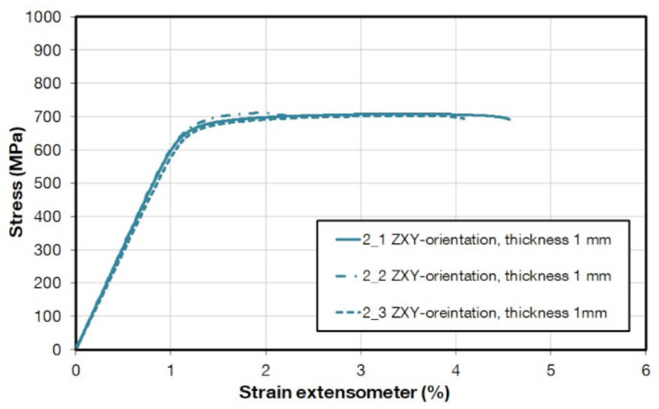
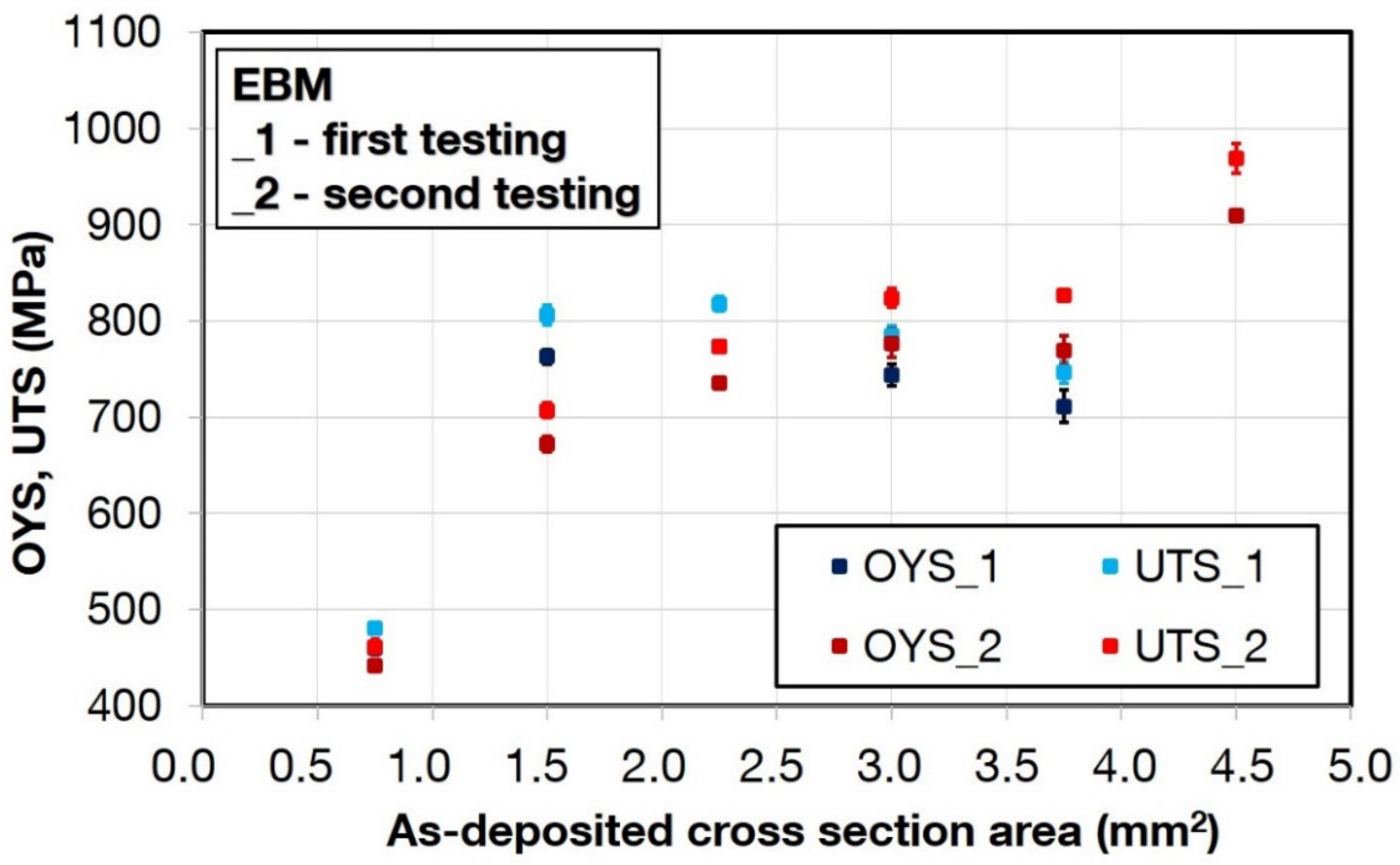
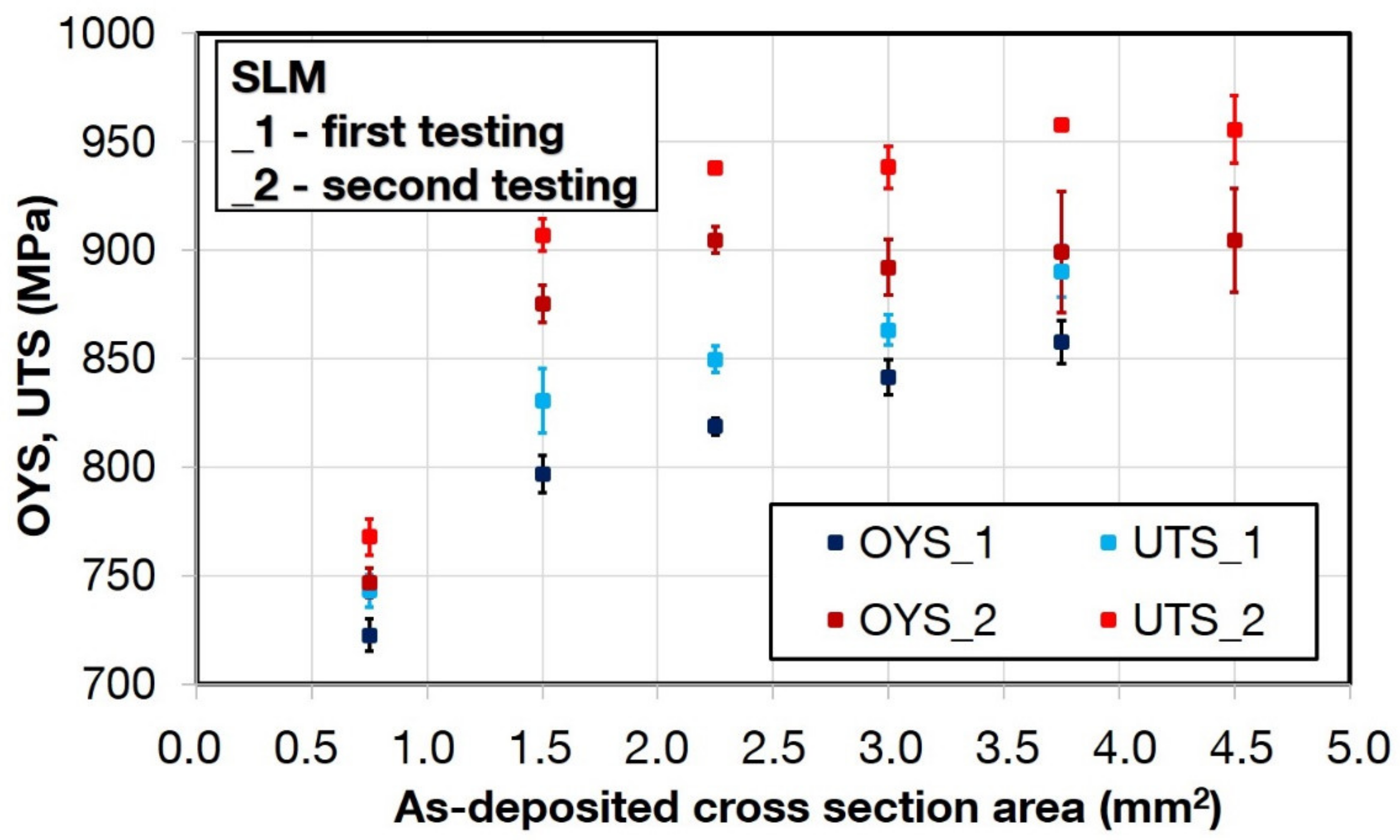
3.1. Tensile Properties
3.2. Build Orientation Effects for EBM Samples
3.3. Results for Miniature M-TT Specimens
3.4. Microstructure and Fractography
4. Discussion
4.1. Sample Thickness
4.2. Build Orientation Effects
4.3. Usability of M-TT Specimens
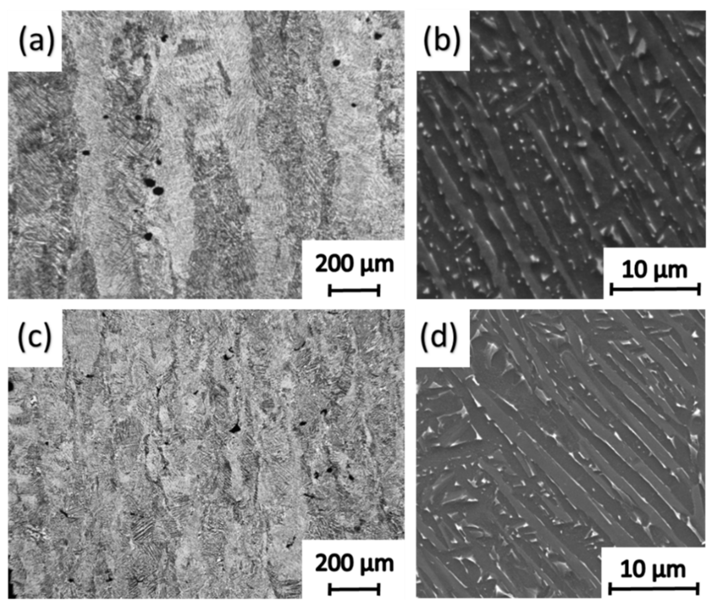
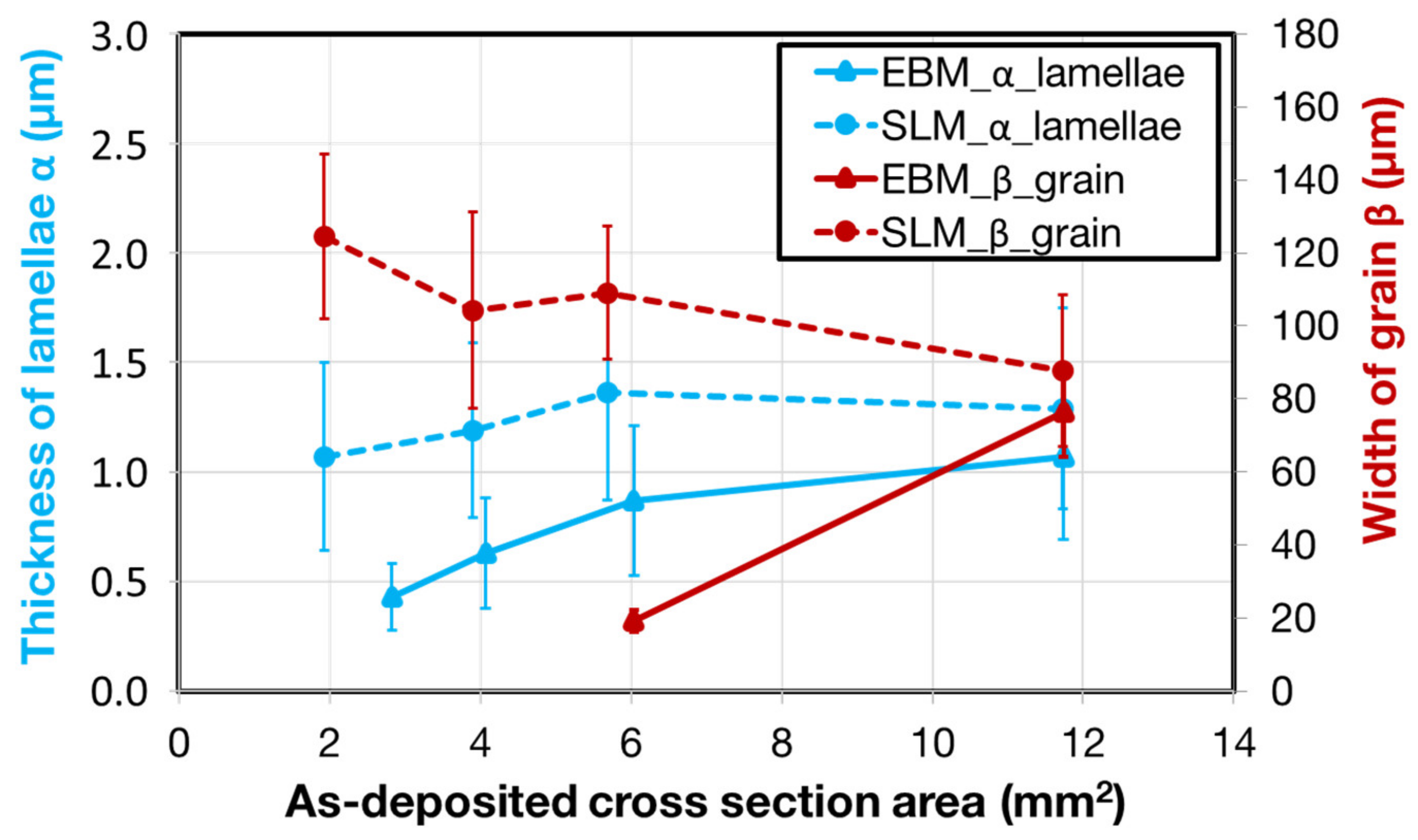
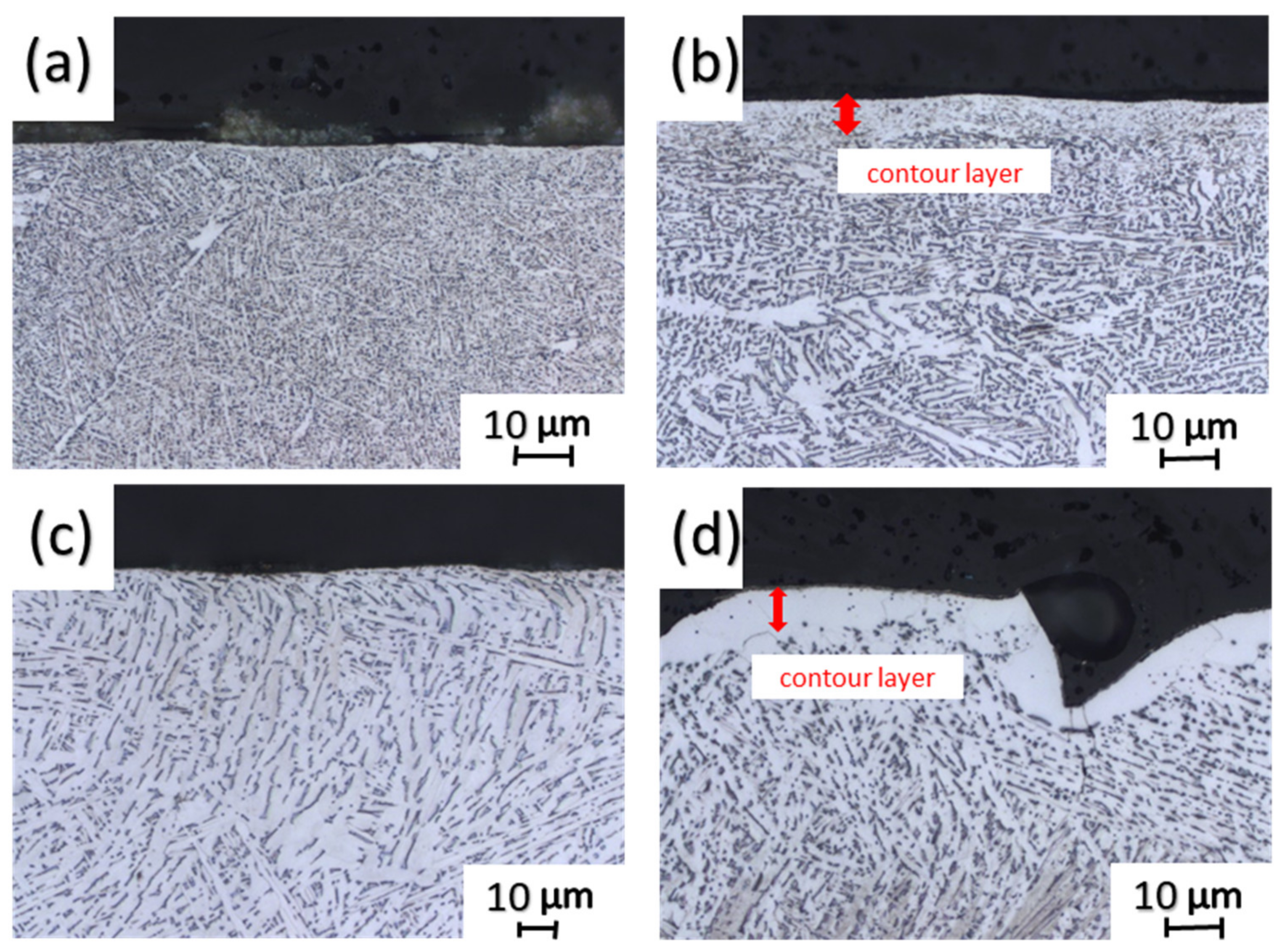
4.4. Microstructure
4.5. Connection of Microstructure and Mechanical Properties
5. Conclusions
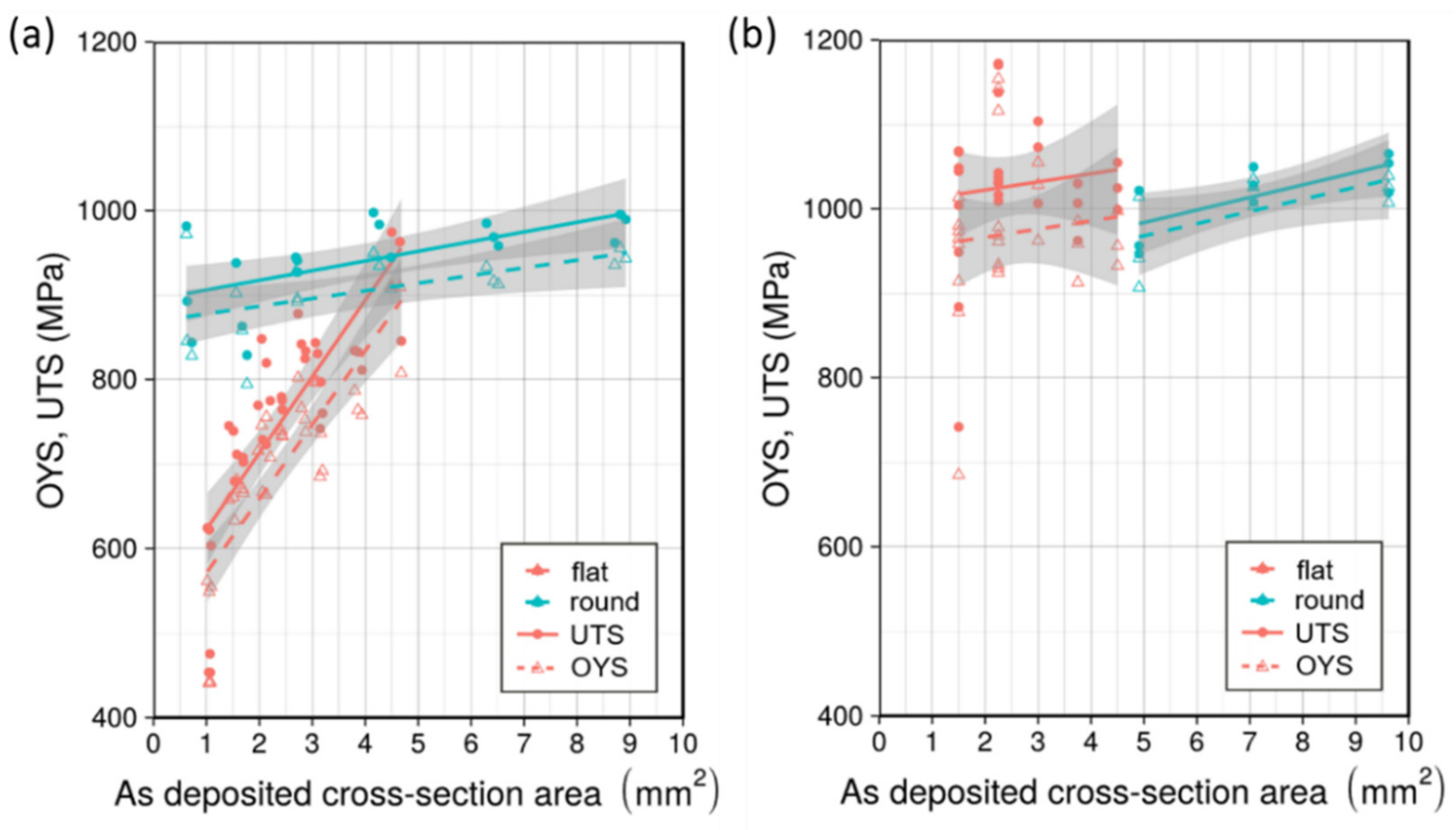
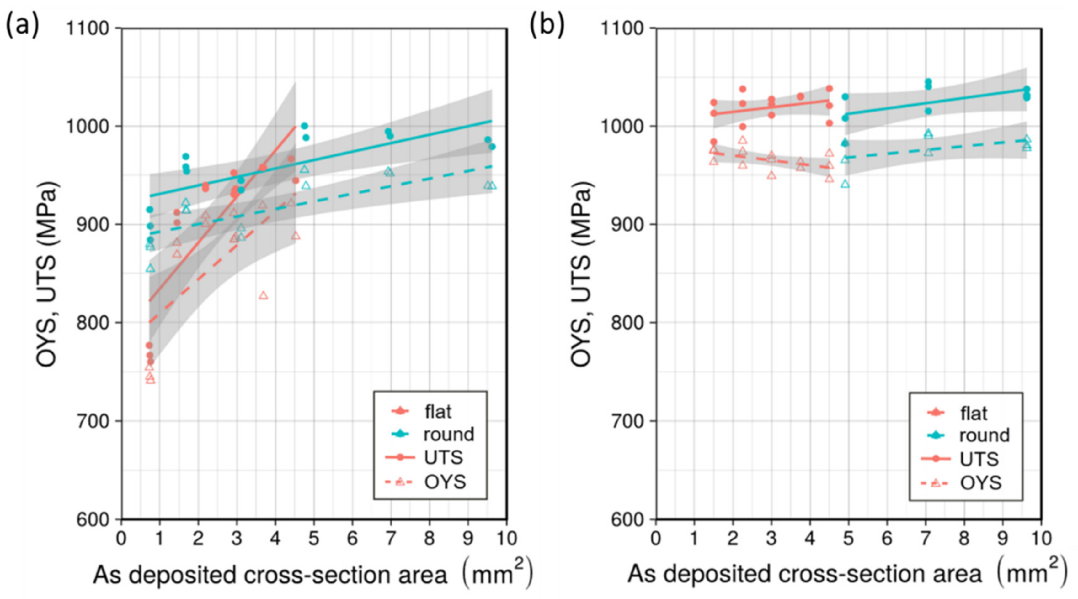
- Mechanical properties of EBM-processed specimens are dependent on the as-deposited sample thickness. Differences in results obtained on the machined specimens is related to differences in the microstructures at the different thicknesses.
- The effects of the as-deposited sample thickness on mechanical properties was less apparent in the SLM-processed specimens [13] as these were all given the same stress relief treatment prior to testing. The mechanical properties for both the flat and round samples stabilized after reaching a certain sample thickness.
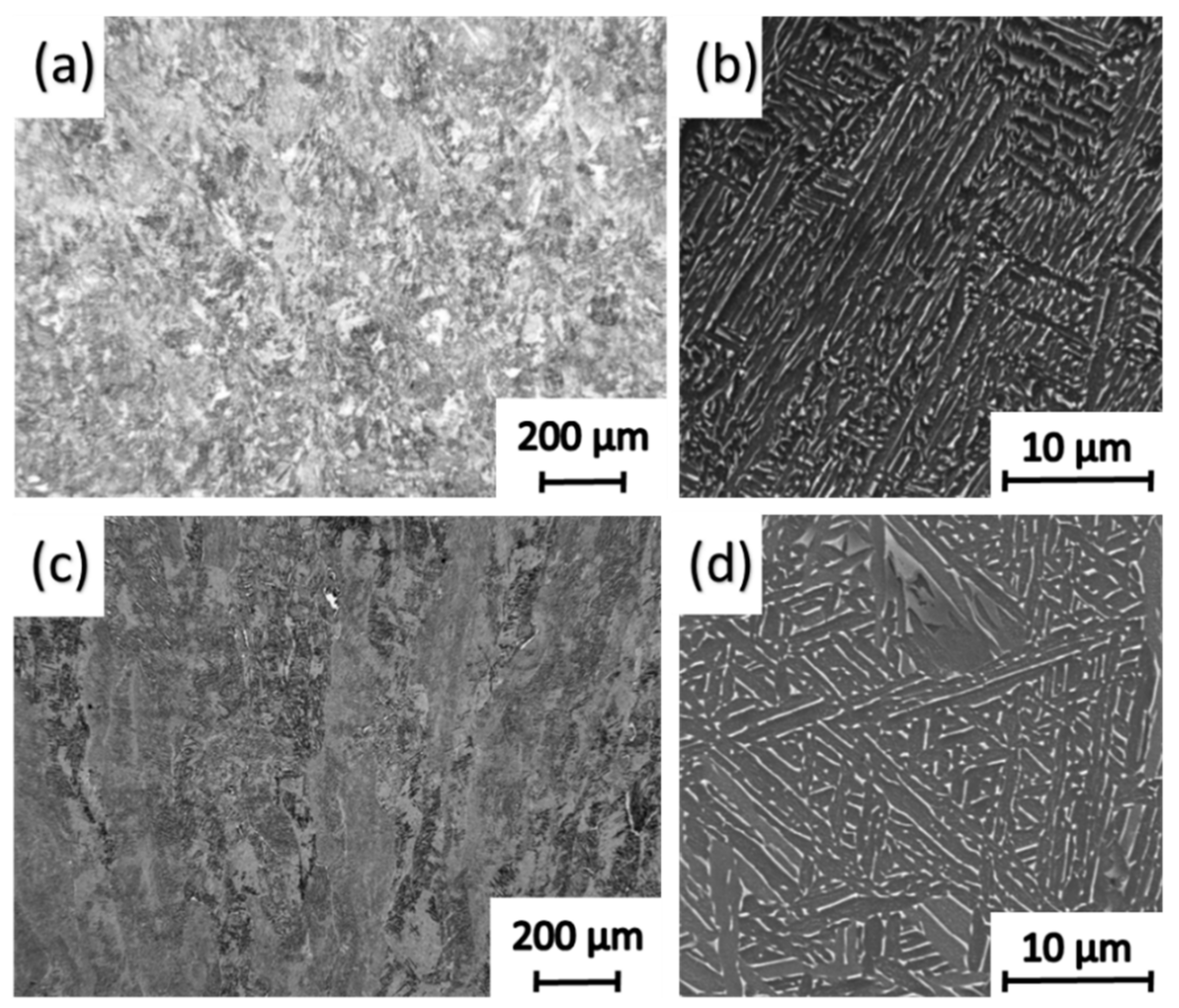
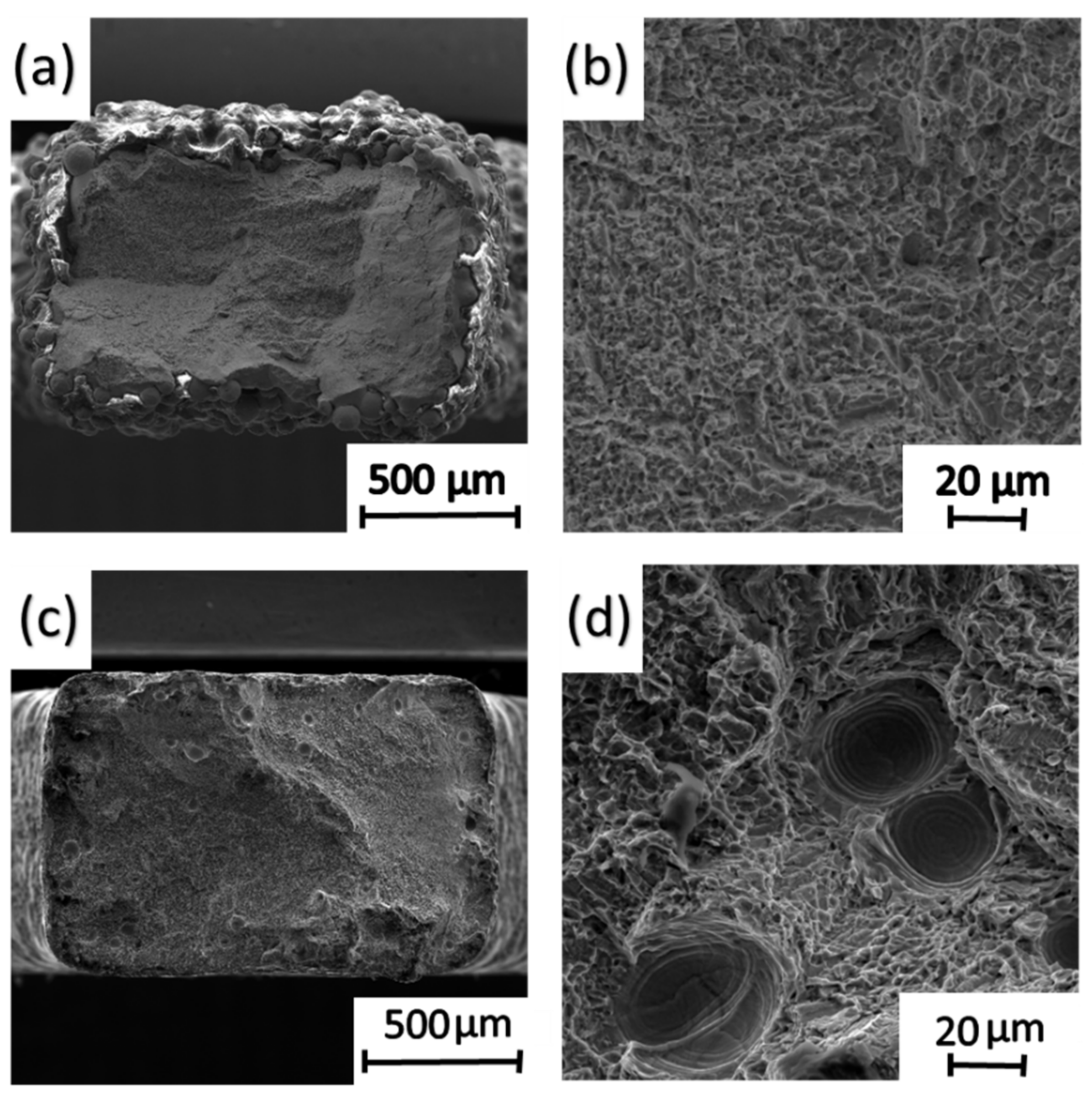
- Values for the mechanical properties (tensile yield strength, ultimate tensile strength) are affected by differences in the microstructural features, including the α-lamellae thickness, amount and type of porosity, and the width of the prior-beta grains. Both metallography and fractography analyses were conducted in this regard.
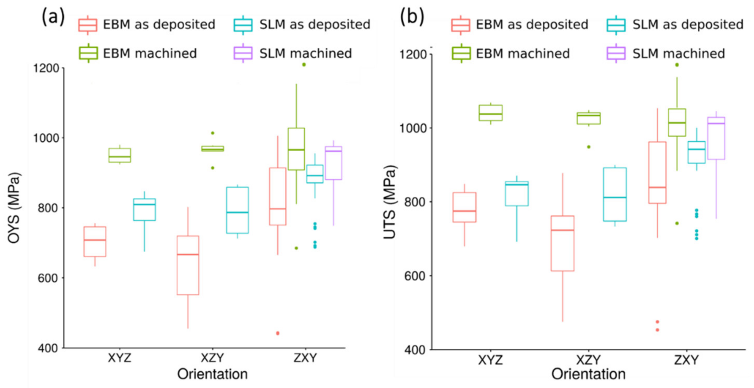
- The results obtained for the as-deposited vs. machined samples revealed that the mechanical properties were mostly affected by the as-deposited (i.e., rough) sample surfaces present for the as-deposited samples. However, testing of the machined samples revealed a more significant role of the microstructural differences on the subsequent mechanical properties.
- The results for both as-deposited and machined M-TT samples of Ti-6Al-4V are broadly useful for estimating the effects of changes in sample thickness, orientation, and processing technique(s) on mechanical properties, and are broadly relevant to such issues on components/parts.
Author Contributions
Funding
Conflicts of Interest
References
- Srinivas, M.; Babu, B.S. A Critical Review on Recent Research Methodologies in Additive Manufacturing. Mater. Today Proc. 2017, 4, 9049–9059. [Google Scholar] [CrossRef]
- Harun, W.; Kamariah, M.; Muhamad, N.; Ghani, S.A.C.; Ahmad, F.; Mohamed, Z. A review of powder additive manufacturing processes for metallic biomaterials. Powder Technol. 2018, 327, 128–151. [Google Scholar] [CrossRef]
- Niinomi, M.; Nakai, M.; Hieda, J. Development of new metallic alloys for biomedical applications. Acta Biomater. 2012, 8, 3888–3903. [Google Scholar] [CrossRef] [PubMed]
- Bose, S.; Ke, D.; Sahasrabudhe, H.; Bandyopadhyay, A. Additive manufacturing of biomaterials. Prog. Mater. Sci. 2018, 93, 45–111. [Google Scholar] [CrossRef]
- Attar, H.; Calin, M.; Zhang, L.-C.; Scudino, S.; Eckert, J. Manufacture by selective laser melting and mechanical behavior of commercially pure titanium. Mater. Sci. Eng. A 2014, 593, 170–177. [Google Scholar] [CrossRef]
- Sallica-Leva, E.; Jardini, A.; Fogagnolo, J.B. Microstructure and mechanical behavior of porous Ti–6Al–4V parts obtained by selective laser melting. J. Mech. Behav. Biomed. Mater. 2013, 26, 98–108. [Google Scholar] [CrossRef]
- Lewandowski, J.J.; Seifi, M. Metal Additive Manufacturing: A Review of Mechanical Properties. Annu. Rev. Mater. Res. 2016, 46, 151–186. [Google Scholar] [CrossRef] [Green Version]
- Frazier, W.E. Metal Additive Manufacturing: A Review. J. Mater. Eng. Perform. 2014, 23, 1917–1928. [Google Scholar] [CrossRef]
- Nguyen, D.S.; Park, H.S.; Lee, C.M. Optimization of selective laser melting process parameters for Ti-6Al-4V alloy manufacturing using deep learning. J. Manuf. Process. 2020, 55, 230–235. [Google Scholar] [CrossRef]
- Sun, W.; Ma, Y.; Huang, W.; Zhang, W.; Qian, X. Effects of build direction on tensile and fatigue performance of selective laser melting Ti6Al4V titanium alloy. Int. J. Fatigue 2020, 130, 105260. [Google Scholar] [CrossRef]
- Hrabe, N.W.; Quinn, T.P. Effects of processing on microstructure and mechanical properties of a titanium alloy (Ti–6Al–4V) fabricated using electron beam melting (EBM), part 1: Distance from build plate and part size. Mater. Sci. Eng. A 2013, 573, 264–270. [Google Scholar] [CrossRef]
- Safdar, A.; He, H.; Snis, A.; De Paz, L.E.C.; Wei, L.-Y. Effect of process parameters settings and thickness on surface roughness of EBM produced Ti-6Al-4V. Rapid Prototyp. J. 2012, 18, 401–408. [Google Scholar] [CrossRef]
- Dzugan, J.; Seifi, M.; Prochazka, R.; Rund, M.; Podany, P.; Konopík, P.; Lewandowski, J. Effects of thickness and orientation on the small scale fracture behaviour of additively manufactured Ti-6Al-4V. Mater. Charact. 2018, 143, 94–109. [Google Scholar] [CrossRef]
- Phutela, C.; Aboulkhair, N.T.; Tuck, C.; Ashcroft, I. The Effects of Feature Sizes in Selectively Laser Melted Ti-6Al-4V Parts on the Validity of Optimised Process Parameters. Materials 2019, 13, 117. [Google Scholar] [CrossRef] [Green Version]
- Rund, M.; Prochazka, R.; Konopík, P.; Dzugan, J.; Folgar, H. Investigation of Sample-size Influence on Tensile Test Results at Different Strain Rates. Procedia Eng. 2015, 114, 410–415. [Google Scholar] [CrossRef] [Green Version]
- Razavi, S.; Van Hooreweder, B.; Berto, F. Effect of build thickness and geometry on quasi-static and fatigue behavior of Ti-6Al-4V produced by Electron Beam Melting. Addit. Manuf. 2020, 101426. [Google Scholar] [CrossRef]
- Pehlivan, E.; Roudnicka, M.; Dzugan, J.; Koukolikova, M.; Králík, V.; Seifi, M.; Lewandowski, J.J.; Dalibor, D.; Daniel, M. Effects of build orientation and sample geometry on the mechanical response of miniature CP-Ti Grade 2 strut samples manufactured by laser powder bed fusion. Addit. Manuf. 2020, 101403. [Google Scholar] [CrossRef]
- Sepe, R.; Franchitti, S.; Borrelli, R.; Di Caprio, F.; Armentani, E.; Caputo, F. Correlation between real geometry and tensile mechanical behaviour for Ti6Al4V electron beam melted thin specimens. Theor. Appl. Fract. Mech. 2020, 107, 102519. [Google Scholar] [CrossRef]
- Prochazka, R.; Dzugan, J. Strain controlled cyclic tests on miniaturized specimens. IOP Conf. Ser. Mater. Sci. Eng. 2017, 179, 12060. [Google Scholar] [CrossRef]
- Dzugan, J.; Sibr, M.; Konopík, P.; Prochazka, R.; Rund, M. Mechanical properties determination of AM components. IOP Conf. Ser. Mater. Sci. Eng. 2017, 179, 12019. [Google Scholar] [CrossRef]
- ASTM WK49229. New Guide for Orientation and Location Dependence Mechanical Properties for Metal Additive Manufacturing; Work in Progress; ASTM WK49229: West Conshohocken, PA, USA.
- Ahmed, T.; Rack, H. Phase transformations during cooling in α+β titanium alloys. Mater. Sci. Eng. A 1998, 243, 206–211. [Google Scholar] [CrossRef]
- Rafi, H.K.; Karthik, N.V.; Gong, H.; Starr, T.L.; Stucker, B.E. Microstructures and Mechanical Properties of Ti6Al4V Parts Fabricated by Selective Laser Melting and Electron Beam Melting. J. Mater. Eng. Perform. 2013, 22, 3872–3883. [Google Scholar] [CrossRef]
- Tan, X.; Kok, Y.; Toh, W.Q.; Tan, Y.J.; Descoins, M.; Mangelinck, D.; Tor, S.B.; Leong, K.F.; Chua, C.K. Revealing martensitic transformation and α/β interface evolution in electron beam melting three-dimensional-printed Ti-6Al-4V. Sci. Rep. 2016, 6, 26039. [Google Scholar] [CrossRef] [PubMed] [Green Version]
- Yan, M.; Yu, P. An Overview of Densification, Microstructure and Mechanical Property of Additively Manufactured Ti-6Al-4V—Comparison among Selective Laser Melting, Electron Beam Melting, Laser Metal Deposition and Selective Laser Sintering, and with Conventional Powder. Sinter. Tech. Mater. 2015. [Google Scholar] [CrossRef]
- Parthasarathy, J.; Starly, B.; Raman, S.; Christensen, A. Mechanical evaluation of porous titanium (Ti6Al4V) structures with electron beam melting (EBM). J. Mech. Behav. Biomed. Mater. 2010, 3, 249–259. [Google Scholar] [CrossRef] [PubMed]
- Bandyopadhyay, A.; Espana, F.; Balla, V.K.; Bose, S.; Ohgami, Y.; Davies, N.M. Influence of porosity on mechanical properties and in vivo response of Ti6Al4V implants. Acta Biomater. 2010, 6, 1640–1648. [Google Scholar] [CrossRef] [PubMed] [Green Version]
- Wang, X.; Xu, S.; Zhou, S.; Xu, W.; Leary, M.; Choong, P.; Qian, M.; Brandt, M.; Xie, Y. Topological design and additive manufacturing of porous metals for bone scaffolds and orthopaedic implants: A review. Biomaterials 2016, 83, 127–141. [Google Scholar] [CrossRef]
- Fousova, M.; Vojtěch, D.; KUBÁSEK, J.; Jablonska, E.; Fojt, J. Promising characteristics of gradient porosity Ti-6Al-4V alloy prepared by SLM process. J. Mech. Behav. Biomed. Mater. 2017, 69, 368–376. [Google Scholar] [CrossRef]
- Seifi, M.; Salem, A.A.; Satko, D.; Shaffer, J.; Lewandowski, J.J. Defect distribution and microstructure heterogeneity effects on fracture resistance and fatigue behavior of EBM Ti–6Al–4V. Int. J. Fatigue 2017, 94, 263–287. [Google Scholar] [CrossRef]
- Fousova, M.; Vojtěch, D.; Doubrava, K.; Daniel, M.; Lin, C.-F. Influence of Inherent Surface and Internal Defects on Mechanical Properties of Additively Manufactured Ti6Al4V Alloy: Comparison between Selective Laser Melting and Electron Beam Melting. Materials 2018, 11, 537. [Google Scholar] [CrossRef] [Green Version]
- Sun, Y.; Aindow, M.; Hebert, R.J. Comparison of virgin Ti-6Al-4V powders for additive manufacturing. Addit. Manuf. 2018, 21, 544–555. [Google Scholar] [CrossRef]
- Sun, Y.; Aindow, M.; Hebert, R.J.; Sun, Y.; Aindow, M.; Hebert, R.J. Materials at High Temperatures The effect of recycling on the oxygen distribution in Ti-6Al-4V powder for additive manufacturing. Mater. High Temp. 2017, 3409, 1–8. [Google Scholar]
- Tang, H.P.; Qian, M.; Liu, N.; Zhang, X.Z.; Yang, G.Y.; Wang, J. Effect of Powder Reuse Times on Additive Manufacturing of Ti-6Al-4V by Selective Electron Beam Melting. JOM 2015, 67, 555–563. [Google Scholar] [CrossRef]
- Xu, W.; Brandt, M.; Sun, S.; Elambasseril, J.; Liu, Q.; Latham, K.; Xia, K.; Qian, M. Additive manufacturing of strong and ductile Ti–6Al–4V by selective laser melting via in situ martensite decomposition. Acta Mater. 2015, 85, 74–84. [Google Scholar] [CrossRef]
- Sallica-Leva, E.; Caram, R.; Jardini, A.; Fogagnolo, J. Ductility improvement due to martensite α′ decomposition in porous Ti–6Al–4V parts produced by selective laser melting for orthopedic implants. J. Mech. Behav. Biomed. Mater. 2016, 54, 149–158. [Google Scholar] [CrossRef]


| AM Technology | Weight (%) | |||||||
|---|---|---|---|---|---|---|---|---|
| Ti | Al | V | C | Fe | O | N | H | |
| EBM | Balance | 6.49 | 4.01 | 0.02 | 0.18 | 0.07 | 0.02 | 0.001 |
| AM Technology | Powder Size (µm) | ||
|---|---|---|---|
| D10 | D50 | D90 | |
| EBM | 55 | 76 | 106 |
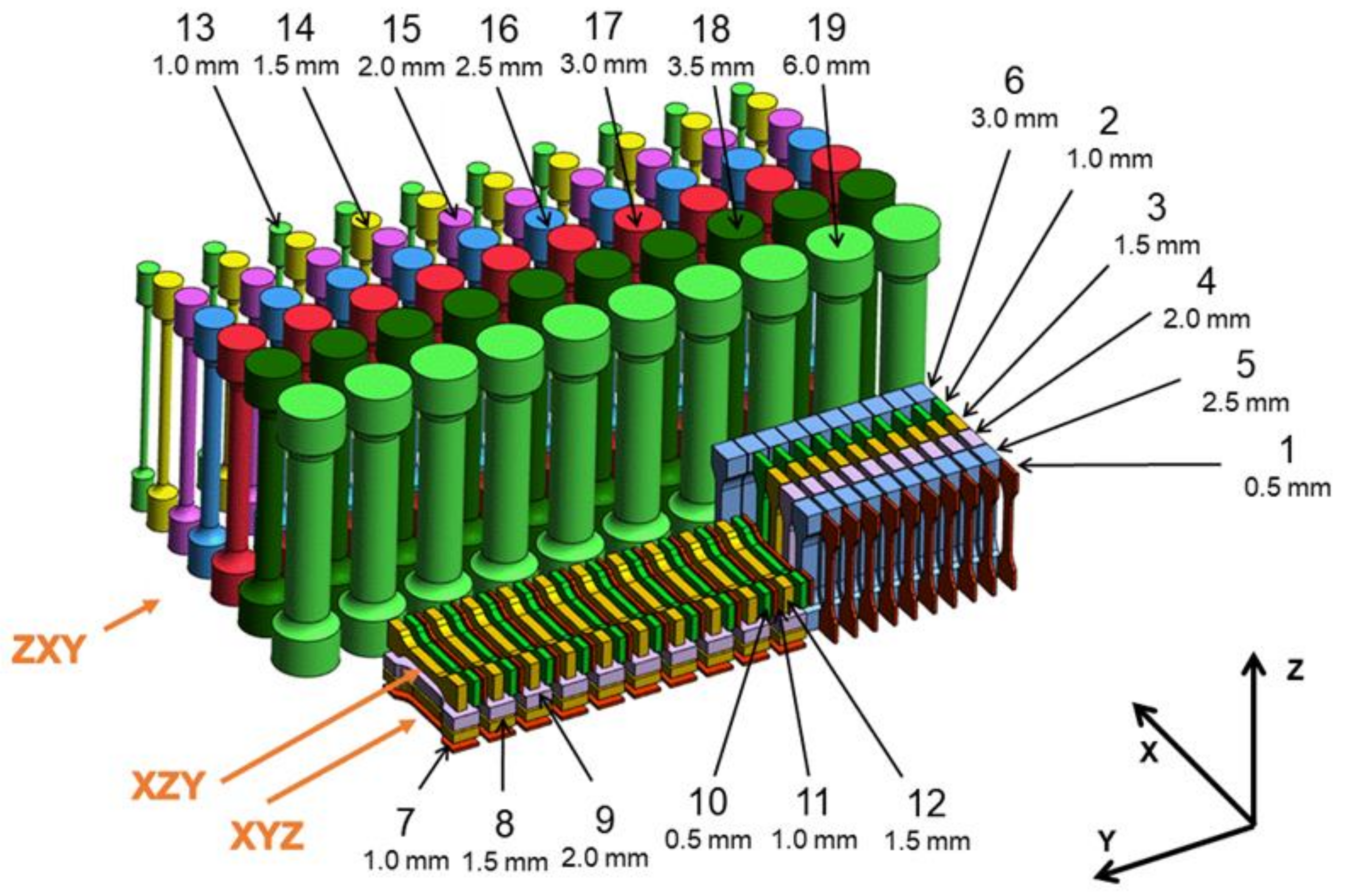
| Data Set | Original Diameter (mm) | Original Thickness (mm) | As-Deposited Cross Section Area (mm2) | Orientation |
|---|---|---|---|---|
| 1 | - | 0.5 | 0.75 | ZXY |
| 2 | - | 1.0 | 1.50 | ZXY |
| 3 | - | 1.5 | 2.25 | ZXY |
| 4 | - | 2.0 | 3.00 | ZXY |
| 5 | - | 2.5 | 3.75 | ZXY |
| 6 | - | 3.0 | 4.50 | ZXY |
| 7 | - | 1.0 | 1.50 | XYZ |
| 8 | - | 1.5 | 2.25 | XYZ |
| 9 | - | 2.0 | 3.00 | XYZ |
| 10 | - | 0.5 | 0.75 | XZY |
| 11 | - | 1.0 | 1.50 | XZY |
| 12 | - | 1.5 | 2.25 | XZY |
| 13 | 0.5 | - | 0.79 | ZXY |
| 14 | 1.0 | - | 1.77 | ZXY |
| 15 | 1.5 | - | 3.14 | ZXY |
| 16 | 2.0 | - | 4.91 | ZXY |
| 17 | 2.5 | - | 7.07 | ZXY |
| 18 | 3.0 | - | 9.62 | ZXY |
| 19 | 6.0 | - | 28.26 | ZXY |
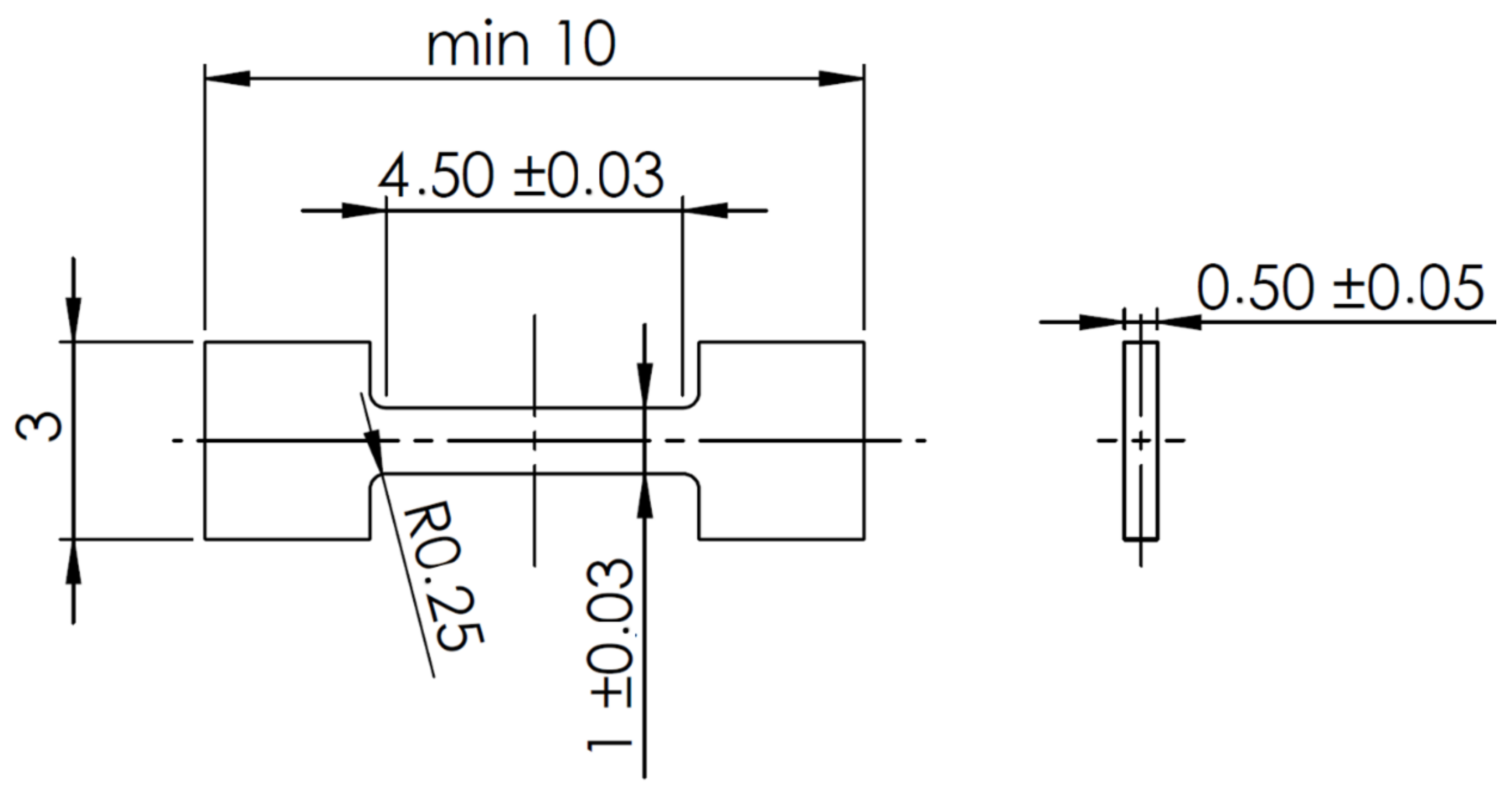
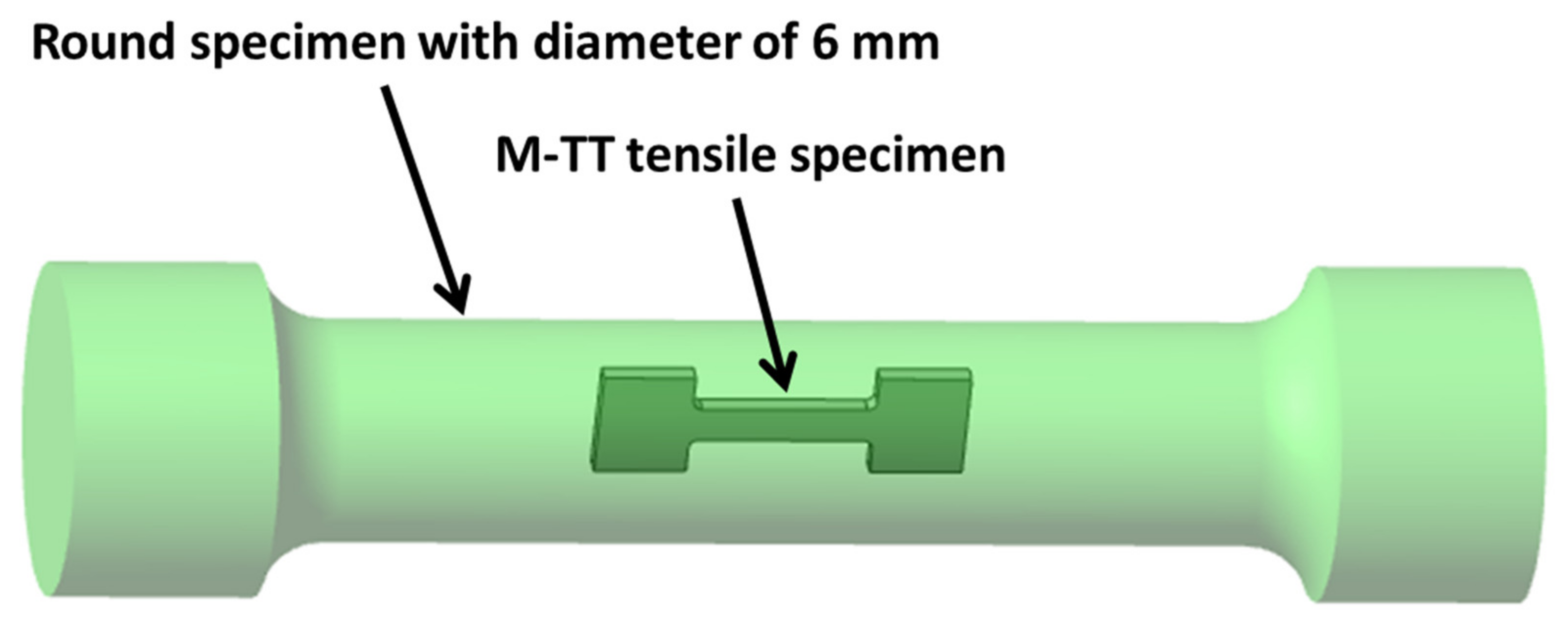
| Method | Data Set | As-Deposited Cross Section Area (mm2) | Value | OYS | UTS |
|---|---|---|---|---|---|
| (MPa) | (MPa) | ||||
| EBM | M-TT reduced section | 0.50 | Average | 1034.2 | 1104.3 |
| Standard deviation | 19.8 | 35.5 | |||
| 6 ZXY | 22.89 | Average | 1052.9 | 1093.8 | |
| Standard deviation | 2.6 | 4.7 | |||
| SLM | M-TT reduced section | 0.50 | Average | 988.0 | 1038.7 |
| Standard deviation | 10.4 | 9.9 | |||
| 6 ZXY | 22.89 | Average | 976.3 | 1025.0 | |
| Standard deviation | 12.0 | 3.8 |
| Method | As-Deposited Cross Section Area (mm2) | Average Porosity (%) | Thickness of Lamellae α (µm) | Width of Prior-β Grains (µm) |
|---|---|---|---|---|
| SLM | 0.75 | 0.38 | 1.07 ± 0.43 | 124.5 ± 22.5 |
| 1.50 | 0.14 | 1.19 ± 0.40 | 104.3 ± 26.8 | |
| 2.25 | 0.10 | 1.36 ± 0.49 | 109.1 ± 18.2 | |
| 4.50 | 0.30 | 1.29 ± 0.46 | 87.7 ± 20.9 | |
| EBM | 0.75 | 0.07 | 0.43 ± 0.15 | - |
| 1.50 | 0.05 | 0.63 ± 0.25 | - | |
| 2.25 | 0.10 | 0.87 ± 0.34 | 19.3 ± 3.0 | |
| 4.50 | 0.24 | 1.07 ± 0.38 | 76.4 ± 18.2 |
© 2020 by the authors. Licensee MDPI, Basel, Switzerland. This article is an open access article distributed under the terms and conditions of the Creative Commons Attribution (CC BY) license (http://creativecommons.org/licenses/by/4.0/).
Share and Cite
Mertová, K.; Džugan, J.; Roudnická, M.; Daniel, M.; Vojtěch, D.; Seifi, M.; Lewandowski, J.J. Build Size and Orientation Influence on Mechanical Properties of Powder Bed Fusion Deposited Titanium Parts. Metals 2020, 10, 1340. https://doi.org/10.3390/met10101340
Mertová K, Džugan J, Roudnická M, Daniel M, Vojtěch D, Seifi M, Lewandowski JJ. Build Size and Orientation Influence on Mechanical Properties of Powder Bed Fusion Deposited Titanium Parts. Metals. 2020; 10(10):1340. https://doi.org/10.3390/met10101340
Chicago/Turabian StyleMertová, Kateřina, Ján Džugan, Michaela Roudnická, Matěj Daniel, Dalibor Vojtěch, Mohsen Seifi, and John J. Lewandowski. 2020. "Build Size and Orientation Influence on Mechanical Properties of Powder Bed Fusion Deposited Titanium Parts" Metals 10, no. 10: 1340. https://doi.org/10.3390/met10101340