


1 Introduction
Understanding the confinement of energetic alpha particles generated by fusion is a long-standing goal of the worldwide fusion research programme (Kolesnichenko Reference Kolesnichenko1980; Fasoli et al. Reference Fasoli, Gormenzano, Berk, Breizman, Briguglio, Darrow, Gorelenkov, Heidbrink, Jaun and Konovalov2007; Gorelenkov, Pinches & Toi Reference Gorelenkov, Pinches and Toi2014). Energetic ions are subject to redistribution and radial loss due to both classical orbit phenomena (first-orbit loss, ripple) and magnetohydrodynamics (MHD) (sawteeth, neoclassical tearing modes (NTMs) and Alfvén eigenmodes (AEs)). These phenomena can potentially impair system performance due to loss of plasma self-heating, but typically the most dangerous consequence is localized heating of plasma-facing components.
The use of discrete coils to generate the toroidal magnetic field in a tokamak causes the field strength to vary slightly in the toroidal direction at constant  $R$ and
  $Z$. This variation, termed toroidal field (TF) ‘ripple’, breaks the axisymmetry of the toroidal field. It has been appreciated since the early days of fusion research that ripple can cause radial transport – and loss – of energetic ions (Artsimovich, Mirnov & Strelkov Reference Artsimovich, Mirnov and Strelkov1965; Stringer Reference Stringer1972; Connor & Hastie Reference Connor and Hastie1973; Goldston, White & Boozer Reference Goldston, White and Boozer1981) that could lead to excessive localized heating and failure of plasma-facing components. So-called ‘ripple-trapped’ ions with very small pitch angle that are effectively trapped in the shallow magnetic well between adjacent TF coils as well as the much larger population of banana-trapped ions are susceptible to ripple-induced transport.
The magnitude of ripple-induced transport is an increasing function of the ripple amplitude, and the ripple amplitude is a function of the number of TF coils and their size relative to the plasma. For a given plasma size, the ripple-induced fast-ion loss can be reduced by either increasing the number of TF coils or the coil size. Both approaches affect the cost and diagnostic access of tokamak designs: increasing the number of TF coils increases cost and deceases access, while increasing the TF coil size increases cost and increases access. Thus, TF ripple is an essential consideration in the design of all burning plasma experiments.
This paper evaluates ripple-induced fast-ion loss in the SPARC tokamak design (Creely et al. Reference Creely, Greenwald, Ballinger, Brunner, Canik, Doody, Fülöp, Garnier, Granetz and Gray2020). We use two existing numerical codes, ASCOT (Varje et al. Reference Varje, Särkimäki, Kontula, Ollus, Kurki-Suonio, Snicker, Hirvijoki and Äkaslompolo2019) and SPIRAL (Kramer et al. Reference Kramer, Budny, Bortolon, Fredrickson, Fu, Heidbrink, Nazikian, Valeo and Van Zeeland2013a), to compute the orbits of alpha particles in the rippled magnetic field from birth at 3.5 MeV until they either thermalize or hit the wall. Because the orbit simulations are rather time-consuming, they have been carried out not for the SPARC V2 design but for its immediate predecessor (V1E), which had slightly smaller ripple (0.15 % versus 0.3 % at the outer edge) but identical plasma conditions (toroidal field, plasma current, major radius, minor radius, elongation:  $B_T, I_p, R_0, a, \kappa$). First, for a number of TF coil configurations, we compute the ripple magnitude as a function of the number of TF coils and as a function of how well the TF coils are aligned. Then we compute the fraction of lost-alpha power for these configurations to the last closed flux surface (LCFS) and its poloidal and toroidal spatial variation. We then extend the orbit simulations from the LCFS to a candidate SPARC wall shape to obtain an estimate of the alpha particle contribution to the wall heat load. Finally, we estimate the surface heating due to alpha losses that would occur in the SPARC V2 coil design based on the V1E simulations.
As in all tokamaks, the ripple magnitude  $\delta (R,Z)$ in SPARC is small at the plasma centre but rises rapidly toward the edge. Ripple-induced radial transport of energetic ions increases with the ripple magnitude, so the transport is typically small at the plasma center, where most of the alphas are born (73 % are born inside
  $\rho _{\textrm {pol}} < 0.6$ where the radial coordinate
  $\rho _{\textrm {pol}} = \sqrt {(\varPsi - \varPsi _o)/(\varPsi _e - \varPsi _o)}$, where
  $\varPsi _o, \varPsi _e, \varPsi$ are the poloidal flux values at the magnetic axis, plasma edge and local position, respectively). The edge ripple for the SPARC V1E design is approximately 0.15 %, which is on the low end of the ripple values for other deuterium-tritium tokamak designs (FIRE, ITER).
To provide a preview of results, we find that ripple-induced alpha power loss to the LCFS is negligible ( ${\sim } 0.25\,\%$) for the SPARC V1E design with 18 perfectly aligned TF coils. The ripple-induced power loss is sub-dominant to first-orbit loss (2.8 %), and few alphas born at
  $\rho _{\textrm {pol}} < 0.8$ are lost. There is modest concentration of the alpha loss poloidally and minimal concentration toroidally. The computed alpha loss naturally increases as the TF coils are assumed to be more and more poorly aligned, but in addition the losses become more concentrated toroidally, so the peak surface power density increases rapidly with coil misalignment. A specific recommendation for the maximum allowable coil misalignment awaits an optimization study of candidate first-wall shapes, but the results of this study suggest that coil misalignments greater than 0.7 cm may be problematic.
We find that recessing the front surface of the radio-frequency (RF) antennas 1 cm behind adjacent protective limiters is sufficient to greatly reduce power deposited onto the antennas. Finally, we find that losses of the energetic ion tail driven by RF heating should also be small in the nominal SPARC V1E plasma.
Since first-orbit and ripple losses of the alpha population are expected to be small in SPARC, it should provide an opportunity to study alpha redistribution and loss due to sawteeth, NTMs and AEs. In the last section, we evaluate the parametric scaling of the drive and damping terms for AEs, and the relative speed of the alpha particles at birth to the Alfvén velocity, to assess whether SPARC might experience this MHD activity and thus provide an opportunity to study it. We also evaluate the expected toroidal mode number of the most unstable AEs. We find that SPARC's parameter space for AE physics is roughly comparable to that for inductive plasmas in the ARC demonstration pilot plant (Sorbom et al. Reference Sorbom, Ball, Palmer, Mangiarotti, Sierchio, Bonoli, Kasten, Sutherland, Barnard and Haakonsen2015), and thus AE physics studies conducted in SPARC should provide useful guidance for expected AE behaviour in ARC.
2 Computed ripple magnitude in SPARC
The TF ripple in a tokamak arises from the fact that the toroidal field is generated by a discrete set of coils, so that the magnetic field is slightly stronger in the plane of a TF coil than half-way between adjacent TF coils. The ripple magnitude  $\delta (R,Z)$ in a tokamak with
  $N$ TF coils is defined by
 \begin{equation} \delta (R,Z) = (B_{\max} - B_{\min}) / (B_{\max} + B_{\min}) ,\end{equation}
where the maxima and minima are the extrema of the field values as one proceeds along the toroidal direction  $\phi$ at constant
  $R$ and
  $Z$. Note that the ripple term has
  $N$-fold symmetry if the TF coils are perfectly aligned.
The ripple  $\delta (R,Z)$ and 3-D magnetic field topology
  $B_{R,\phi ,Z}(R,\phi ,Z)$ were computed numerically by approximating each TF coil as a set of discrete wires that were equally spaced within the defined shape of the TF coil. The number of wires is configurable, but in practice two wires toroidally and two wires radially was determined to be sufficient. Each wire in turn was represented by a set of
  ${\sim }80$ straight wire segments. The magnitude of each wire segment's magnetic field was computed from the Biot–Savart law and the contribution of all wire segments from all of the TF coils was summed to obtain the net magnetic field at each field point. Figure 1 shows the ripple contours for the nominal SPARC V1E TF design, assuming 18 perfectly aligned TF coils. The ripple near the plasma centre is very low (0.0016 %) and rises to a modest 0.15 % at the outer plasma edge (
 $R=R_0+a$) at the midplane.
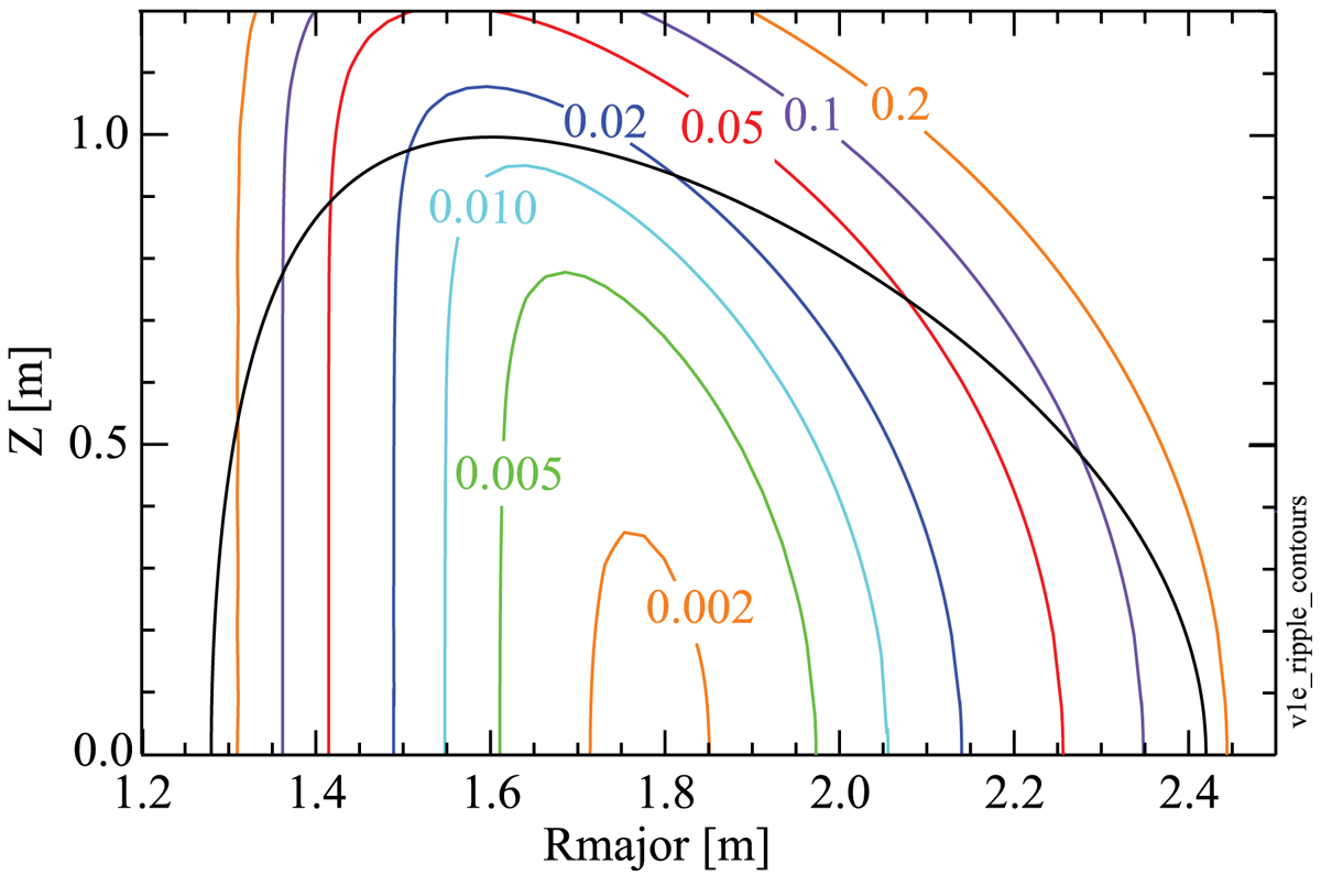
Figure 1. Computed ripple contours (in per cent) for the SPARC V1E design, assuming perfect alignment of the 18 TF coils. The black line is the LCFS.
These values are so low that it raises the question of whether the ripple and associated alpha losses in a ‘real-world’ SPARC with imperfectly manufactured coils or imperfectly positioned coils could be dominated by those imperfections rather than by the discreteness of the TF coil set. As discussed below, the ripple near the plasma centre can in fact be dominated by even relatively small coil displacements, while the edge ripple is mostly defined by the TF coil discreteness.
Four types of TF coil displacements are considered here: up/down, in/out, toroidal offset and vertical tilt, where vertical tilt is a rotation of the coil about an axis along the major-radius direction at the midplane. For each case, candidate displacements (in metres) are sampled from a normal distribution with a specified standard deviation  $\sigma$, but candidate displacements larger than 1.5
 $\sigma$ are excluded. For the toroidal and vertical-tilt calculations, the displacement in metres is converted into a displacement angle by dividing it by the outer major radius of the TF coil or the vertical height of the TF coil, respectively. Figure 2 illustrates the toroidal offset and vertical tilt misalignments; perfectly aligned TF coils are shown in black and misaligned coils are shown in red. The superconducting tokamak KSTAR, which is approximately the same size as SPARC V1E , achieved a TF coil alignment accuracy of approximately 1 mm (Yang et al. Reference Yang, Kim, Kim, Sa, Kim, Kim, Hong, Kim, Kim and Kim2006) but we consider displacement ensembles with
  $\sigma$ up to 3.6 cm.
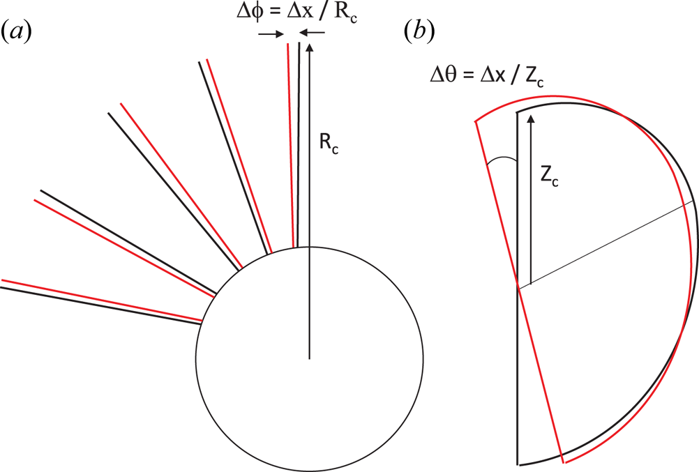
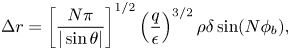
Figure 2. Cartoon illustrating (a) a plan view of the ensemble of toroidal displacements and (b) an elevation view of a single TF coil vertical tilt misalignment. In both cases a distance  ${\rm \Delta} x$ sampled from a normal distribution with standard deviation
  $\sigma$ is converted into an angular displacement by dividing by the coil major radius or elevation.
When the TF coil set is assumed to be perfectly aligned, the toroidal magnetic field is periodic in the toroidal direction. However, when various TF coil misalignments are allowed, then the toroidal magnetic field is no longer periodic; effectively, TF coil misalignments will add some low- $N$ perturbation to the toroidal magnetic field in addition to the high-
 $N$ (
$N$ ( $N=18$) generated by the discreteness of the TF coils. This is not a problem for the alpha orbit simulations, which work directly from the computed 3-D magnetic field. For configurations involving misaligned TF coils, we will adopt the definition that the ripple is equal to the average of the ripple evaluated for each of the individual 18 TF sectors.
Figure 3 plots the average ripple on the midplane for various types of TF coil displacements. In all cases, the magnitude of the displacements was computed from a normal distribution with  $\sigma = 1.43$ cm. The most ‘dangerous’ displacements are toroidal offsets and in/out displacements (at large and small major radius
  $R_{\textrm {major}}$, respectively). Up/down displacements generate little ripple and vertical tilts generate negligible ripple. Note that while the torodial and in/out displacements significantly increase the ripple at the plasma centre, by more than an order of magnitude, the absolute magnitude of the central ripple remains low, below 0.1 %. Well off the midplane (
 $Z = 0.50, 0.75$ m) and close to the plasma edge, the ripple for up/down misalignments becomes comparable to the ripple for toroidal misalignments. The ripple for vertical tilts remains negligible everywhere.
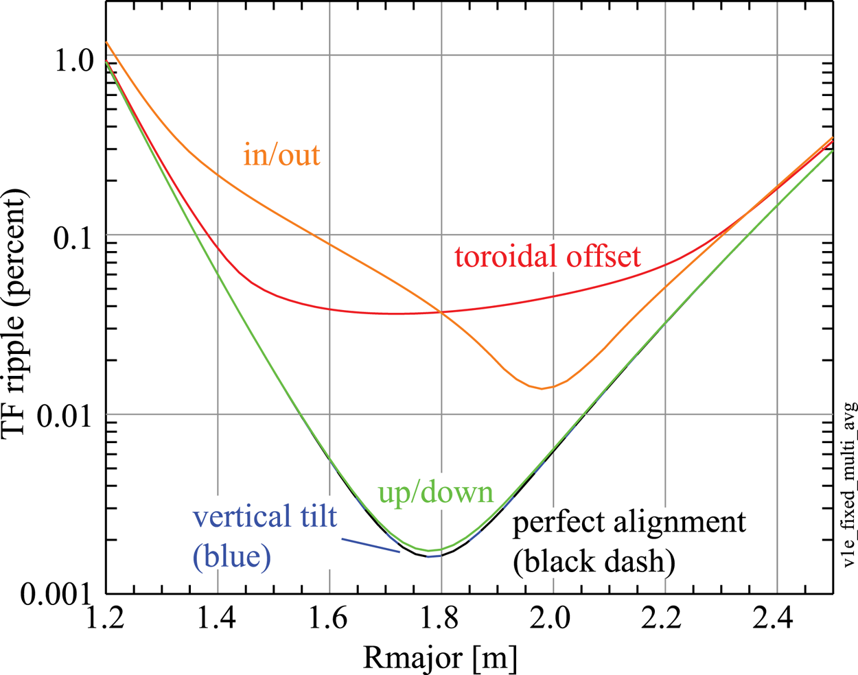
Figure 3. Comparison of average TF ripple on the horizontal midplane for various directions of TF coil displacements.
Figure 4(a) plots the average TF ripple as a function of major radius for several assumed values of  $\sigma$. As shown in figure 4(b), the computed ripple near the center of the TF coils is a nearly linear function of
  $\sigma$. Note that, to first order, the linear increase in ripple magnitude going from perfect alignment to worst alignment is about the same at the plasma centre and plasma edge. So, effectively, coil misalignments add about the same absolute ripple magnitude everywhere in the plasma; the effect seems ‘big’ at the plasma centre because, in the absence of misalignments, the ripple there is very low.
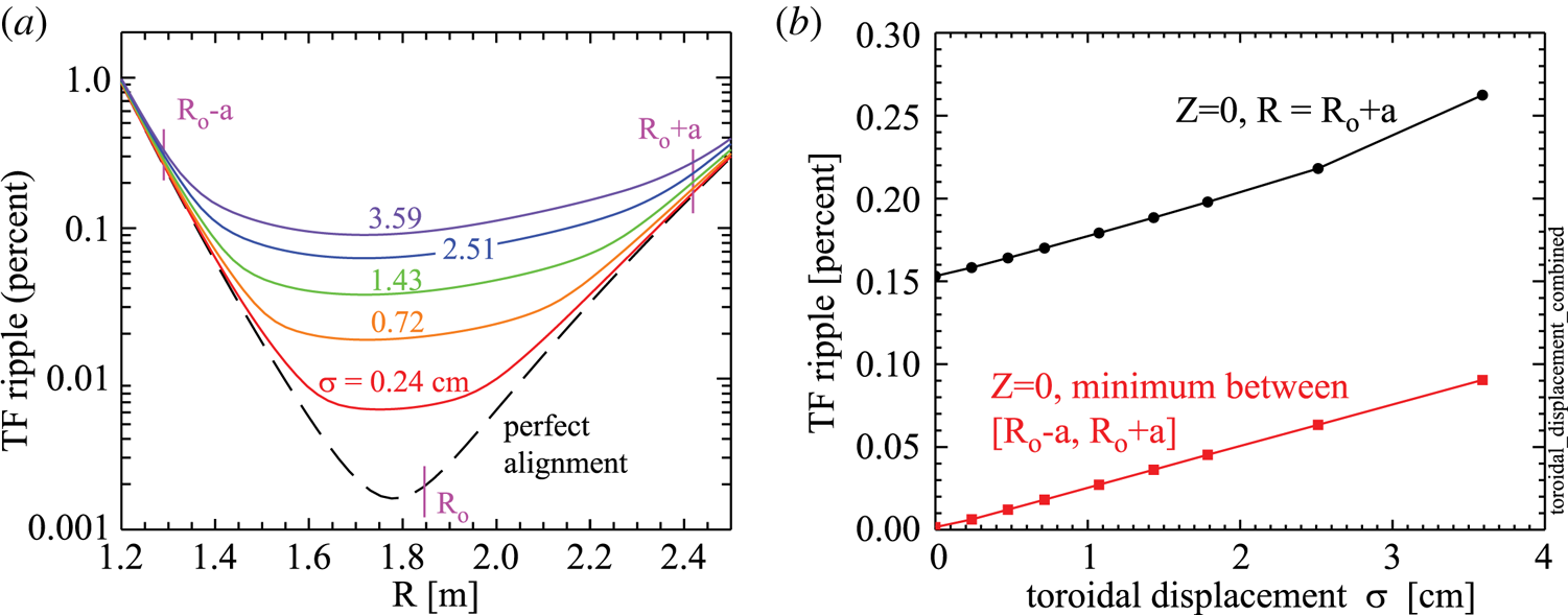
Figure 4. Average TF ripple on the horizontal midplane as a function of TF coil displacement.
The fact that relatively severe toroidal displacements of TF coils has such a weak effect on ripple (e.g. central and edge ripple increase by 0.084 % and 0.104 % for  $\sigma =3.6$ cm) may seem counter-intuitive. A partial explanation is that, within the plane of a TF coil, only 21 % of the toroidal field is generated by the coil itself; 33 % is generated by its neighbouring coils, 19 % is generated by the next two neighbouring coils and 10 % is generated by the subsequent two neighbouring coils. So, at any point in the plasma, roughly five to seven closest TF coils contribute significantly to the local magnetic field. This effectively averages the field perturbations caused by individual TF coil misalignments and reduces the ripple that would occur otherwise.
3 Ripple loss mechanisms
The issue of possible ripple-induced ion losses has been known since the 1970s and there is an extensive ripple literature, both theoretical and experimental. The dominant ripple-induced loss mechanisms are ripple trapping and stochastic banana diffusion; collisional ripple diffusion (Catto Reference Catto2018) is typically a weaker loss mechanism and will not be considered here.
Ripple trapping. In the absence of TF ripple, the  $\boldsymbol {B} \times \boldsymbol {\nabla } B$ vertical drift experienced by an ion cancels at the top and bottom of its orbit. However, if the ion has only a very small parallel velocity,
  $|v_\parallel / v| < \sqrt (\delta ) \approx 0.04$ for
  $\delta = 0.15$ %, the ion cannot climb out of the local magnetic ‘well’ between adjacent TF coils and so it drifts vertically out of the plasma (Stringer Reference Stringer1972; Connor & Hastie Reference Connor and Hastie1973). Rotational transform reduces the effective ripple depth, thereby reducing the ripple-induced transport, and the wells disappear entirely for
  $\alpha ^* = \epsilon |\sin \theta | / (Nq\delta ) > 1$, where
  $\epsilon = r/a$,
  $\theta$ is the poloidal angle,
  $N$ is the number of TF coils and
  $q$ is the local safety factor. Ripple trapping losses affect only a small fraction of fast ions near the plasma edge (where the ripple is large), but the lost surface power density can be concentrated both toroidally and poloidally. The losses will be concentrated at either the top or bottom of the torus, depending on the direction of the
  $\boldsymbol {B} \times \boldsymbol {\nabla } B$ drift.
Stochastic ripple diffusion. in the presence of ripple banana-trapped ions experience an additional radial excursion from a flux surface  ${\rm \Delta} r$ that, for circular plasma, is given by
 \begin{equation} {\rm \Delta} r = \left[\frac{ N{\rm \pi}}{|\sin \theta|} \right]^{1/2} \left(\frac{q}{\epsilon} \right)^{3/2} \rho \delta \sin (N\phi_b), \end{equation}
where  $\rho$ is the gyroradius and all variables including the poloidal (
 $\theta$) and toroidal (
 $\phi$) angles are evaluated at the banana tip. If
  ${\rm \Delta} r$ is sufficiently large, the radial excursions on successive banana tips become decorrelated, and the ion experiences a rapid radial diffusion. One model (Goldston et al. Reference Goldston, White and Boozer1981) for the threshold for stochastic ripple diffusion to occur is given approximately by ripple magnitude
  $\delta _s$, where
 \begin{equation} \delta > \delta_s = \left(\frac{\epsilon}{N{\rm \pi} q} \right)^{3/2} \left(\frac{1}{2\rho q^{\prime}} \right), \end{equation}
where  $q^{\prime } = \textrm {d}q/\textrm {d}r$. This expression yields only fair agreement with measurements on TFTR (Boivin, Zweben & White Reference Boivin, Zweben and White1993; Redi et al. Reference Redi, Zarnstorff, White, Budny, Janos, Owens, Schivell, Scott and Zweben1995a,Reference Redi, Budny, Darrow, Doung, Fisher, Janos, Mcchesney, Mccune, Medley and Petrovb; White et al. Reference White, Goldston, Redi and Budny1998), so it should be viewed as characterizing the approximate plasma region susceptible to stochastic ripple diffusion. Banana-trapped ions that experience stochastic ripple diffusion tend to diffuse outward in major radius (see figure 3 in Zweben et al. Reference Zweben, Darrow, Batha, Budny, Diesso, Herrmann, Giarrusso, Redi, Takahashi and Von Goeler1998), so their loss region is typically concentrated on the outboard major radius.
Figure 5(a) illustrates the plasma regions that are susceptible to the ripple-trapping and stochastic ripple diffusion mechanisms for V1E SPARC TF coil design. Note that, in addition to being in the susceptible region spatially, ions must also satisfy conditions on pitch angle ( $|v_\parallel /v| < \delta ^{1/2}$ for ripple trapping,
  $|v_\parallel /v| < \epsilon ^{1/2}$ for stochastic banana diffusion) to experience rapid ripple-induced radial transport. Also note that some ions that undergo ripple-trapping transport near the horizontal midplane will drift vertically out of the susceptible region and thereby become confined once again. Ripple is effectively a loss mechanism that operates only at the edge for the nominal SPARC V1E design. As shown in figure 5(b), the analytic theory indicates that ripple should remain an edge-loss mechanism even if the TF coil set is assumed to have substantial toroidal-offset displacements (
 $\sigma = 1.43$ cm). For this reason, we expect ripple-induced alpha power losses to be small in SPARC, because few alphas are born in the lossy edge region: only 27 % of alphas are born at
  $\rho _{\textrm {pol}} > 0.6$ and only 9 % are born at
  $\rho _{\textrm {pol}} > 0.8$.
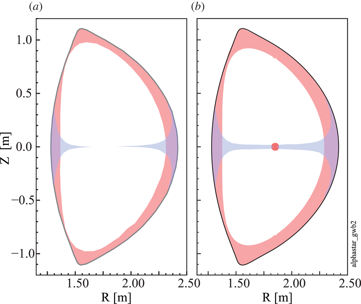
Figure 5. Plasma regions that are susceptible to stochastic ripple banana-drift diffusion (pink) and ripple trapping (blue) for SPARC V1E design. (a) Nominal case assuming 18 perfectly aligned TF coils; and (b) perturbed case assuming toroidally displaced TF coils with displacement  $\sigma =1.43$ cm.
4 Numerical simulation tools
A number of numerical ion orbit-simulation codes have been developed (ORBIT (White & Chance Reference White and Chance1984), OFMC (Tobita et al. Reference Tobita, Tani, Neyatani, van Blokland, Miura, Fujita, Takeuchi, Nishitani, Matsuoka and Takechi1992), ASCOT (Varje et al. Reference Varje, Särkimäki, Kontula, Ollus, Kurki-Suonio, Snicker, Hirvijoki and Äkaslompolo2019), LOCUST (Akers et al. Reference Akers, Verwichte, Martin, Lake and Fasoli2012) and SPIRAL (Kramer et al. Reference Kramer, Budny, Bortolon, Fredrickson, Fu, Heidbrink, Nazikian, Valeo and Van Zeeland2013a)) to compute the orbits of energetic ions in the presence of rippled 3-D magnetic fields. These codes effectively advance an ion's position  $\boldsymbol {x} = (R,\phi , Z)$ with
  $\delta \boldsymbol {x} = \boldsymbol {v} \delta t$ and its change in velocity vector
  $\delta \boldsymbol {v}$ with
  $\delta \boldsymbol {v} = (\boldsymbol {F}/m)\delta t$ by computing the Lorentz force (
 $\boldsymbol {F} = q \boldsymbol {v} \times \boldsymbol {B}$) experienced by the ion in the local magnetic field as it moves through the plasma. The simulations can include the effect of pitch angle scattering and slowing down due to collisions with the plasma ions and electrons. The more recent SPIRAL and ASCOT codes can also include the effects of radial electric fields, 3-D magnetic field configurations (not necessarily toroidally periodic) and even time-varying magnetic fields due to MHD activity. The intersection of a lost-ion orbit with the wall can be computed for both 2-D and 3-D wall-shape configurations, which allows an evaluation of the surface power density. Small time steps are required to avoid spurious numerically induced orbit drift. Of the order of
  $10^4$ ions must be followed for reasonably accurate estimates of the fractional power lost (Snicker, Hirvijoki & Kurki-Suonio Reference Snicker, Hirvijoki and Kurki-Suonio2013) and
  $10^5$ ions must be followed for reasonably accurate estimates of the localized surface power density (Snicker, Sipilä & Kurki-Suonio Reference Snicker, Sipilä and Kurki-Suonio2012), so these orbit simulations are computationally expensive. However, the fast ions do not interact with one another, so the computation of each fast-ion orbit is independent of the calculation of the other fast-ion orbits, and the computational ‘problem’ is naturally parallelizable.
The ASCOT code has been used extensively to simulate fast-ion behaviour in a large number of tokamak experiments including DIII-D (Kramer et al. Reference Kramer, Mclean, Brooks, Budny, Chen, Heidbrink, Kurki-Suonio, Nazikian, Koskela, Schaffer, Shinohara, Snipes and Van Zeeland2013b), JET (Fundamenski et al. Reference Fundamenski, Sipilä, Matthews, Riccardo, Andrew, And Eich, Ingesson, Kiviniemi, Kurki-Suonio and Philipps2002), (Asunta et al. Reference Asunta, Kurki-Suonio, Tala, Sipilä and Salomaa2008) and AUG (Asunta et al. Reference Asunta, Äkäslompolo, Kurki-Suonio, Koskela, Sipilä, Snicker and García-Muñoz2012). ASCOT has also been used to predict alpha losses for ITER for various plasma scenarios (Kurki-Suonio et al. Reference Kurki-Suonio, Asunta, Hellsten, Hynonen, Johnson, Koskela, Lonnroth, Parail, Roccella and Saibene2009, Reference Kurki-Suonio, Akaslompolo, Sarkimaki, Varje, Asunta, Cavinato, Gagliardi, Hirvijoki, Parail and Saibene2016) and in the presence of MHD (Kurki-Suonio et al. Reference Kurki-Suonio, Asunta, Hirvijoki, Koskela, Snicker, Hauff, Jenko, Poli and Sipilä2011; Snicker et al. Reference Snicker, Hirvijoki and Kurki-Suonio2013). Throughout this paper, we report results exclusively from ASCOT version 5.
SPIRAL has been also been used extensively to model fast-ion behaviour in multiple tokamak experiments including the effects of resonant magnetic perturbations (van Zeeland et al. Reference van Zeeland, Ferraro, Grierson, Heidbrink, Kramer, Lasnier, Pace, Allen, Chen and Evans2015), the test tritium breeding module (Kramer et al. Reference Kramer, Budny, Ellis, Gorelenkova, Heidbrink, Kurki-Suonio, Nazikian, Salmi, Schaffer and Shinohara2011, Reference Kramer, Mclean, Brooks, Budny, Chen, Heidbrink, Kurki-Suonio, Nazikian, Koskela, Schaffer, Shinohara, Snipes and Van Zeeland2013b) on DIII-D, and the effects of AEs on DIII-D (Chen et al. Reference Chen, Austin, Heidbrink, Kramer, Nazikian, Pace, Petty and van Zeeland2013, Reference Chen, Kramer, Heidbrink, Fisher, Pace, Petty, Podesta and Van Zeeland2014), the interaction of magnetic perturbations, toroidal Alfvén eigenmodes (TAEs), global Alfvén eigenmodes (GAEs), and fast-ion loss on NSTX (Kramer et al. Reference Kramer, Budny, Bortolon, Fredrickson, Fu, Heidbrink, Nazikian, Valeo and Van Zeeland2013a, Reference Kramer, Bortolon, Ferraro, Spong, Crocker, Darrow, Fredrickson, Kubota, Park and podestá2016). Earlier SPIRAL was also used to predict alpha losses in ITER (Kramer et al. Reference Kramer, White, Nazikian and Berk2008).
The software implementation of the orbit-following physics differs between ASCOT and SPIRAL, and both the underlying physics and numerical algorithms are complicated. For these reasons we are motivated to carefully compare the simulation output from the two codes, which will inform our confidence in the results. The Appendix compares the ASCOT and SPIRAL codes.
5 ASCOT and SPIRAL orbit simulations
The kinetic plasma profiles and magnetic equilibrium for the ASCOT and SPIRAL simulations reported here were extracted from predictive TRANSP simulations of the full-performance SPARC DT scenario (Rodriguez-Fernandez et al. Reference Rodriguez-Fernandez, Howard, Greenwald, Creely, Hughes, Wright, Holland, Lin and Sciortino2020) during the burn flat top. The plasma conditions are  $R_0=1.85$ m,
  $a=0.57$ m,
  $\kappa _{\textrm {sep}} = 1.97$,
  $\delta _{\textrm {sep}} = 0.54$,
  $B_{T} = 12.2$ T,
  $I_p= 8.7$ MA,
  $n_{e0} \approx 4.3 \times 10^{20}\ \textrm {m}^{-3}$,
  $T_{e0} \approx 22.2$ keV,
  $T_{i0} \approx 19.8$ keV,
  $Z_{\textrm {eff}} = 1.5$,
  $P_{\textrm {RF}} = 11$ MW,
  $P_{\textrm {fus}} \approx 110$ MW,
  $P_{\alpha } \approx 22\ \textrm {MW}$ and
  $Q \approx 9$. The direction of the
  $\boldsymbol{\nabla} B$ drift in these simulations is upward. The ICRF heating scenario was He3 minority with a He3 concentration of 5 %. Both codes simulated the full alpha gyro-orbits rather than guiding-centre orbits. An ensemble of typically 20 000 alphas was generated numerically with birth energy
  $E = 3.5\ \textrm {MeV}$ and randomly distributed in space and in the velocity direction. Each alpha was assigned a weight proportional to the local alpha source rate as computed by TRANSP and these weights were used when computing the fractional loss of alpha particles and energy. The collisional orbits were simulated by the codes until the alphas either thermalized (defined as
  $E = 50$ keV for ASCOT or
  $E=2 T_i$ for SPIRAL) or until they crossed the LCFS. The computed alpha positions and velocity vectors that strike the LCFS were stored, and this ensemble of particles was then used as the starting points for ‘daughter’ orbit simulations that track the alpha orbits until they strike a wall surface or thermalize.
6 Simulation results: power loss at LCFS
Although we are ultimately concerned about the surface power density at SPARC's first wall, we first evaluate the alpha power ‘lost’ to the LCFS, i.e. we will regard an alpha as being lost if its  $\rho _{\textrm {pol}}$ exceeds unity. This provides information about where the lost alphas leave the plasma poloidally and toroidally, whereas the location of alpha strike points on a plasma-facing wall will be strongly influenced by fine details of the wall surface shape. The computed losses at a real wall will be smaller than ‘losses’ at the LCFS, because some alphas that cross the LCFS will re-enter the plasma and thermalize. For example, if we construct a candidate wall that is conformal to the LCFS but shifted outward by 2, 4 or 6 cm, the alpha power that hits the wall is a factor 1.6, 2.8 and 5.6 smaller than the alpha power that crosses the LCFS. Unfortunately, to optimize RF coupling in SPARC, the antennas must be close to the LCFS, and the present SPARC design calls for the wall to be only
  ${\sim }1$ cm from the LCFS at the outer midplane.
Figure 6 confirms the expectation based on analytic theory that there is negligible ripple-induced alpha loss – indeed loss from any mechanism – except near the plasma edge for the nominal 18-coil configuration. Figure 6(a) plots the cumulative lost-alpha power, integrated from  $\rho _{\textrm {pol}}=0$, and normalized to the total lost-alpha power, as a function of the poloidal radius
  $\rho _{\textrm {pol}}$ of the alphas at birth. For example, alphas born with
  $\rho _{\textrm {pol}}=0$ to
  $\rho _{\textrm {pol}} \approx 0.8$ account for only 5 % of the total lost-alpha power. Figure 6(b) plots the local fraction of lost-alpha power as a function of the alpha birth
  $\rho _{\textrm {pol}}$, i.e. for each radial bin, the ordinate is the ratio of the lost-alpha power from that bin to the total alpha source power in that bin. For example, for alphas born with
  $\rho _{\textrm {pol}} \approx 0.9$, roughly 50 % of their power will cross the LCFS. In subsequent plots and tables, we will use the value of
  $\rho _{\textrm {pol}}$ at which the alpha power losses exceed 5 % of the total losses as a proxy for the radius at which losses start to become significant; inside this radius the plasma is ‘safe’ with respect to losses. There is good agreement between ASCOT and SPIRAL for both the cumulative and local losses.
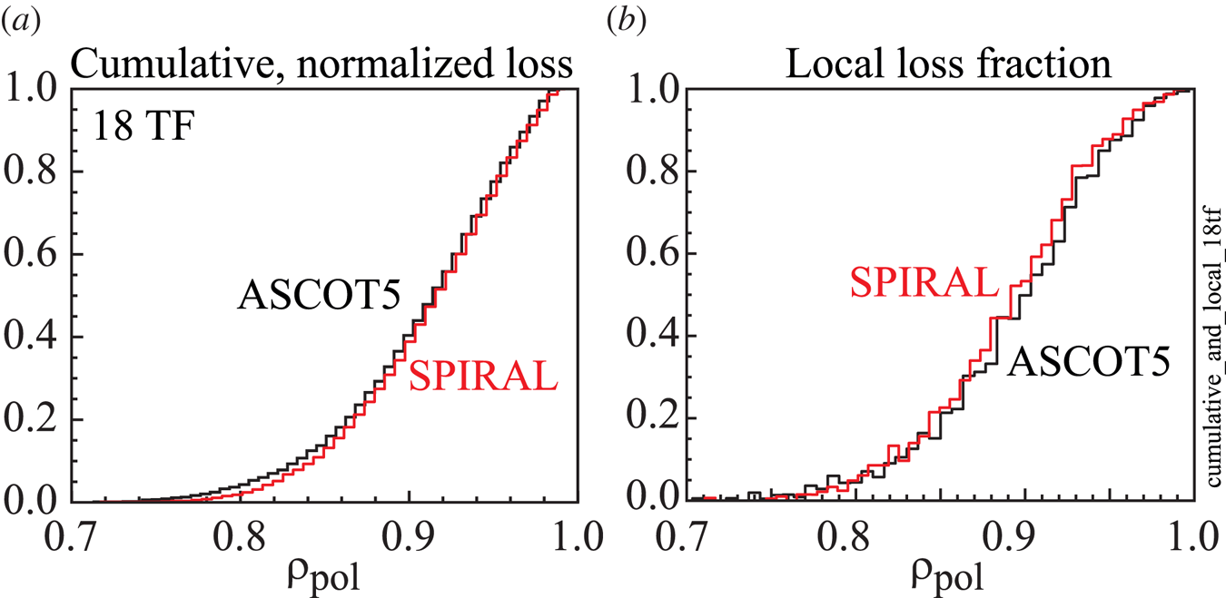
Figure 6. (a) Cumulative, normalized power losses for the nominal 18 TF coil design as a function of the alpha birth  $\rho _{\textrm {pol}}$ and (b) local power loss fraction.
We have carried out a number of ASCOT and SPIRAL alpha simulations for a no-ripple configuration, for the nominal (i.e. perfectly aligned) 18-coil configuration, as well as for 18-coil configurations which allow for varying amplitudes and directions of TF coil displacements. Figure 7 and table 1 summarizes the results. The major observations are as follows.
(i) Alpha power losses increase by only a small amount (
 ${\sim }0.25$ %) between the no-ripple and nominal 18-coil simulations (triangles versus circles at $\sigma =0$), indicating that ripple-induced losses are small.
(ii) In simulations for which the TF coils are displaced toroidally, the alpha power losses increase roughly linearly with assumed
$\sigma$ of the ensemble of TF coil displacements.(iii) The alpha power losses are slightly larger for in/out versus toroidal-offset displacements.
(iv) The alpha power losses are smaller for up/down versus toroidal-offset displacements, consistent with the ripple being smaller for the up/down displacements (figure 3).
(v) There is excellent agreement between the lost-alpha power fraction as computed by ASCOT and SPIRAL.
(vi) There is similarly good agreement from ASCOT and SPIRAL with respect to the 5 % ‘safe’
$\rho _{\textrm {pol}}$, i.e. the maximum radius for which integrated losses are negligible.


Figure 7. (a) Computed percentage of lost-alpha power to the LCFS as a function of  $\sigma$ for various directions of coil displacement. Black, green and blue data points represent ASCOT simulations; the red data points represent SPIRAL simulations. (b) The value of birth
  $\rho _{\textrm {pol}}$ at which the volume-integrated alpha power losses (from
  $\rho _{\textrm {pol}=0}$) equal 5 % of the total alpha power losses.
Table 1. Summary of ASCOT5 and SPIRAL alpha simulations. Numbers for particle and power loss represent percentage of lost-alpha particles and power, respectively.

A closer look at the computed particle- and power-loss fractions in table 1 reveals that the loss fractions computed by SPIRAL are consistently 6.5–7.6 % larger than those computed by ASCOT . The 1- $\sigma$ statistical uncertainty in the power loss fraction in these simulations is surprisingly small (approximately 1 %) because, of the 20 000 simulated alphas, typically 7000 are lost, i.e. roughly one third of the simulated alphas are lost to the LCFS before they thermalize (the corresponding weighted particle- and power-loss fractions are much less because the particles which are lost are born close to the plasma edge, where the alpha source rate is much smaller than at the plasma centre). So, the consistent
  $\sim$7 % difference in the computed power loss fraction between the two codes is several times larger than the statistical uncertainty; the difference is statistically significant.
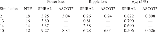
The good agreement between ASCOT and SPIRAL on computed alpha power losses for the no-ripple and nominal (perfectly aligned) 18 TF coil simulations, and as a function of TF coil misalignment provides some assurance that both codes are functioning properly. However, ripple is a sub-dominant loss process to first-orbit losses for many of these simulations, particularly for the no-ripple and nominal 18 TF coil simulations, the latter of which has 2.8 % first-orbit loss and just 0.26 % ripple loss. So, these comparisons do not necessarily inform whether the two codes agree on the computed orbits of alphas subject to stochastic banana-drift diffusion and/or ripple-trapping transport. To address this issue, we have performed alpha-orbit simulations using the SPARC V1E TF coil shape assuming perfect coil alignment, but with a varying number of TF coils ranging from 18 down to 12. As illustrated in figure 8, each reduction of two TF coils roughly doubles the edge ripple. The computed alpha losses rise modestly between the 18- and 16-coil simulations (total alpha power losses:  $3.25\,\% \rightarrow 3.80\,\%$; losses due to ripple:
  $0.26\,\% \rightarrow 0.81\,\%$), and rise considerably as the number of TF coils is reduced to 14 or 12 coils. For the 12-coil simulation the total power losses reach 9.27 %, of which most (6.28 %) is attributable to ripple. Thus, these simulations span the range from ripple losses being sub-dominant (to first-orbit losses) to the ripple losses becoming dominant. As shown in figure 8 and table 2, the agreement between ASCOT and SPIRAL remains good throughout the scan, both with regard to the total alpha power losses but also with regard to the
  $\rho _{\textrm {pol}}$ at which integrated alpha power loss exceeds 5 % of the total loss.

Figure 8. (a) Computed percentage of lost-alpha power for the SPARC V1E coil shape as a function of number of TF coils. (b) The value of birth  $\rho _{\textrm {pol}}$ at which the volume-integrated alpha power losses (from
  $\rho _{\textrm {pol}=0}$) equal 5 % of the total alpha power losses.
Table 2. Summary of ASCOT5 and SPIRAL alpha simulations for a scan of number of TF coils.
For the new SPARC V2 design, the outboard leg of the TF coils was moved inward by approximately 10 cm relative to VIE, which has the effect of doubling ripple at the outer midplane to 0.3 %, while the ripple for  $R<1.8$ remains about the same. The V2 outboard ripple is very close to the value for the SPARC V1E TF design but with 16 TF coils, so, on the basis of the existing V1E simulations, we would expect the alpha power loss in V2 to lie somewhere between the computed losses for V1E at
  $N=16$ and
  $N=18$ coils.
7 Toroidal, poloidal, and pitch-angle dependence of losses
Ripple can increase local surface heating not only by increasing the total alpha power that is lost to the wall, but also by concentrating the loss power toroidally and poloidally. Figure 9 compares the toroidal distribution of the lost-alpha power for the 18- and 12-coil V1E configurations, assuming perfect TF coil alignment. Since the ripple is periodic, the toroidal angle is plotted modulo  $20^{\circ }$ for 18 coils and modulo
  $30^{\circ }$ for 12 coils, to improve the particle statistics. Evidently, the large ripple associated with the 12 coil configuration causes significant toroidal localization, with a peak-to-minimum of about 6. The toroidal localization is much less pronounced for the 18 TF coil configuration, with a peak-to-minimum of about 1.3–1.4. There is excellent agreement between the ASCOT and SPIRAL code calculations of the toroidal distribution of the alpha losses.

Figure 9. Toroidal distribution of lost-alpha power for the (a) 18 TF coil and (b) 12 TF coil configurations. The plots illustrate only the toroidal dependence of the power loss; the vertical scales are in arbitrary units (i.e. in absolute terms the power loss is much higher in the 12 TF coil configuration).
Both neoclassical first-orbit and ripple-induced losses can also result in a poloidal concentration of the lost-alpha power. Figure 10 plots the poloidal distribution of the alpha power losses, showing good agreement between the two codes. The poloidal distributions exhibit negligible loss for  $\theta <0^\circ$ (corresponding to
  $Z<0$).

Figure 10. Poloidal distribution of lost-alpha power at the LCFS for the 18 TF coil configuration. Here  $\theta =0^\circ$ corresponds to the outer midplane and
  $\theta = \pm 180^\circ$ corresponds to the inner midplane;
  $\theta > 0$ for
  $Z>0$ and
  $\theta <0$ for
  $Z<0$.
As a final cross-check of the ASCOT and SPIRAL codes, we compare the initial and final pitch-angle distribution of alphas which are lost to the LCFS in figure 11; there is excellent agreement between the codes.
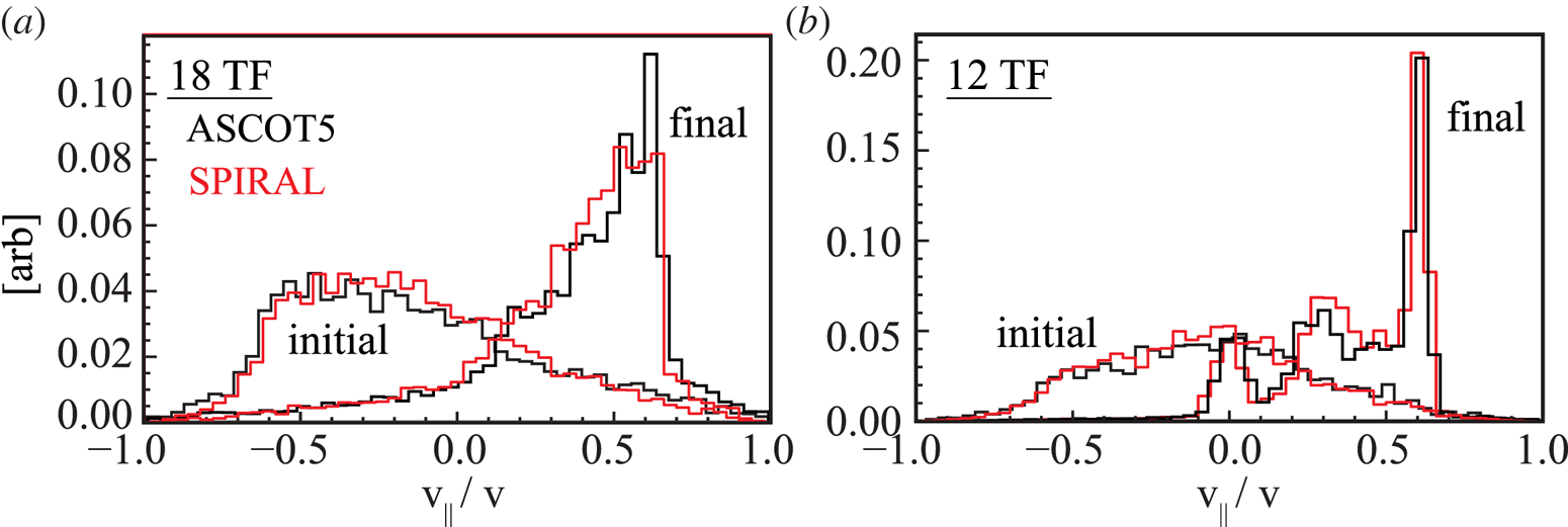
Figure 11. Distribution of birth and final pitch angle for alphas which leave the LCFS as computed by ASCOT and SPIRAL for (a) the nominal 18-coil configuration and (b) the corresponding 12-coil configuration.
8 Surface power density at the wall
Radio-frequency antennas are complicated structures with shape typically dictated by RF-physics considerations rather than robustness to surface heating. For this reason, RF antennas are typically recessed some distance behind adjacent protective limiters. An important design consideration for SPARC is how far must the front surface of the RF antennas be recessed in order to significantly reduce the power loading from lost energetic ions.
Alpha power losses to an ersatz wall (rather than to the LCFS) were computed for an earlier SPARC design, V1D, that had a similar plasma and TF coil shape to V1E , but was slightly smaller ( $R_0 = 1.80$ vs 1.85 m). A 2-D wall was constructed to be conformal to the LCFS but displaced outward by 2 cm. Pairs of toroidally continuous RF antennas were assumed to be positioned above and below the outer midplane with vertical extent 50 cm, starting at
  $Z={\pm}5$ cm. To assess the effectiveness of recessing the RF antennas behind the adjacent wall, at the nominal poloidal extent of the RF antennas, the wall was recessed another 1–2 cm. It was found that recessing the RF antenna 1 cm behind the adjacent wall significantly reduced the lost-alpha power deposited onto the antennas, by a factor of
  ${\sim }40$.
As illustrated in figure 12, a candidate RF system for SPARC comprises 28 antennas mounted in 14 toroidal locations above and below the midplane, extending to  $Z \approx \pm 50$ cm. The antennas are protected by a midplane belt limiter 5 cm tall and vertical TF ‘sector’ limiters 30.5 cm wide, positioned between adjacent RF antennas, extending vertically to the full height of the antennas. All limiters would extend approximately 1 cm beyond the wall, and the front surface of the RF antennas would be 1 cm behind the limiter surface. The remaining four TF sectors would be contiguous and are reserved for diagnostics. The TF sector limiters will be installed in each of the 18 TF sectors, but the midplane belt limiter extends only in the TF sectors with RF antennas (
 ${\rm \Delta} \phi = 280^\circ$).

Figure 12. Positions of alpha strike points on the wall and limiter surfaces as computed by SPIRAL. (a) Nominal 18-coil configuration assuming perfect TF coil alignment. (b) Misaligned TF configuration assuming toroidal offsets with  $\sigma = 3.6$ cm. Orange regions represent the TF sector limiters and blue regions represent the toroidal belt limiter.
SPIRAL simulations have been performed to compute the alpha losses to this wall and limiter configuration. Note that, in these simulations, no attempt has been made to optimize the limiter shape to spread the lost-alpha power as evenly as possible. A simple  $45^\circ$ bevel was applied at all leading limiter edges. So, the computed surface power density at leading edges may have localized ‘hot spots’ that would disappear with an optimized limiter surface shape. Figure 12(a) plots the locations of alpha strike points on the wall and limiter for the nominal 18-coil configuration with perfect TF coil alignment. The data from all 18 TF coils have been superimposed because, without coil misalignments, the orbit losses are periodic. For clarity, only losses with
  $R > 1.70$ m are shown. Several features are evident in this figure: (i) as expected, there is considerable concentration of alpha losses at the leading edges of the both the TF sector and belt limiters; (ii) very few alphas hit the region spanned by the RF antennas; (iii) very few alphas are lost below the horizontal midplane, even on limiter surfaces; and (iv) the distribution of lost alphas is reasonably uniform in
  $[R,\phi ]$ space in the upper-wall region (
 $R>0.5$ m). Point (iii) is unfortunate because it implies that only 14 of the 28 TF sector limiters receive significant lost-alpha power, thereby halving the area over which the lost power is distributed.
Figure 12(b) plots the corresponding losses for an 18 TF coil configuration with toroidally misaligned coils; an extreme example has been chosen ( $\sigma =3.6$ cm) to highlight new features. The coil misalignments generate significant toroidal variation of the losses on both the TF sector limiters and belt limiter, but they generate no toroidal variation in the loss to the upper wall (
 $Z > 0.5$ m). In a few TF sectors, the limiter losses now extend onto the limiters below the midplane, but most of the power is still lost to the limiters above the midplane. We can derive a toroidal ‘peaking’ factor
  $P_{F\phi }$ for the limiters by summing the power losses in each TF sector for which the alphas strike a surface at
  $|Z| < 0.5$ m.
To estimate the surface power density  $S_{\textrm {lim}}$ that might be obtained with a more optimized limiter shape, we will divide the total power deposited onto the limiters by the total limiter area
  $A_{\textrm {lim}}$ (of 14 limiters) and then multiply by an assumed limiter peaking factor
  $P_{F\text {-lim}}$. Here
  $P_{F\text {-lim}}$ characterizes how well an optimized limiter shape distributes the lost power uniformly over the limiter area. In the calculations below we will set
  $P_{F\text {-lim}} = 3$ without justification; future ASCOT and SPIRAL orbit calculations will explore a variety of limiter shapes to determine achievable values of
  $P_{F\text {-lim}}$. The surface power density at the limiter is given by
 \begin{equation} S_{\textrm{lim}} = \frac{P_{\textrm{lim}} P_{F\text{-lim}} P_{F\phi}} {A_{\textrm{lim}}} ,\end{equation}
where  $P_{\textrm {lim}}$ is the computed power deposited onto the limiters. Here
  $P_{F\phi }$ is unity for the case of perfectly aligned TF coils and rises to
  ${\sim }2$ for simulations with the worst assumed TF coil misalignments (ensemble
  $\sigma = 3.6$ cm). For other simulations, the value of
  $P_{F\phi }$ was assumed to scale linearly from
  $P_{F\phi } = 1.0$ at
  $\sigma =0$ to the value at the
  $\sigma =3.6$ cm simulation.
Figure 10 indicates that most of the lost-alpha power in the upper-wall region occurs at  $\theta = 40 \text {--}120^\circ$; this represents a wall arclength of about 0.97 m and an area
  $A_{\textrm {wall}} = 12.2\ \textrm {m}^2$. Over this poloidal extent, the peak-to-average power loss ratio
  $P_{F\theta }$ is about 2.16. So the surface power density in the upper-wall region
  $S_{\textrm {wall}}$ can be computed from
 \begin{equation} S_{\textrm{wall}} = \frac{P_{\textrm{wall}} P_{F\theta} } {A_{\textrm{wall}}}, \end{equation}
where  $P_{\textrm {wall}}$ is the power computed to be lost to the wall for
  $Z>0.5$ m.
The computed surface power densities for several simulations in the scan of toroidal-offset magnitude is tabulated in table 3. Several features of the data are noteworthy. First, the computed power to the upper wall is completely independent of the assumed magnitude of the TF coil misalignment – presumably because these losses are entirely first-orbit losses. Correspondingly, surface power density at the upper wall remains quite modest throughout the scan,  ${\sim }60\ \textrm {kW}\,\textrm {m}^{-2}$. Second, the peak surface power density at the limiters is considerably larger than at the upper wall, in large part because the combined limiter area (
 $2.74\ \textrm {m}^2$ for 18 TF sector limiters) is much smaller than the wall area. The limiter surface power density is still modest for perfectly aligned TF coils (
 $244\ \textrm {kW}\,\textrm {m}^{-2}$), but rises significantly as the assumed magnitude of the misalignment increases. This is a consequence of both increased power deposition onto the limiters and increased toroidal peaking. The acceptable tolerance on TF coil alignment will depend on what is deemed to be an acceptable surface heating power density and/or temperature rise of the limiter surface during a 10-second fusion burn. However, table 3 suggests that a upper bound on the sigma of toroidal coil displacement might lie somewhere between
  $\sigma = 0.7\text {--}1.8$ cm.
Table 3. Computed surface power densities for the scan in toroidal offset, where  $S_{\textrm {lim}}^*$ is the maximum surface power density on the limiter computed directly from SPIRAL.
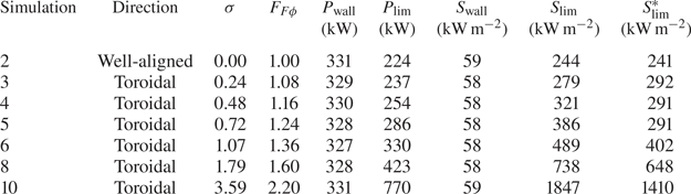
For comparison with the estimated peak surface heat loads computed with the approximations above, the last column of table 3 tabulates the maximum surface power density computed directly from SPIRAL for area elements  $8\ \textrm {cm}\times 1\ \textrm {cm}$ toroidally/vertically. Better particle statistics were available for the ‘well aligned’ case number 2, allowing a calculation for smaller area elements
  $4\ \textrm {cm} \times 0.5\ \textrm {cm}$, which increased the surface power density from 244 to
  $338\ \textrm {kW}\,\textrm {m}^{-2}$, an increase of 38 %. There is considerable statistical uncertainty in both approaches because the calculations are based on only
  ${\sim }7000$ lost alphas (for the perfectly aligned case) and so the rather good agreement between the two approaches may be fortuitous. A definitive evaluation of the maximum surface power density will require both a more realistic wall shape and simulations that follow more alphas.
9 Ripple-induced losses of RF tail ions
The ICRF heating in SPARC will include He3-minority and H-minority scenarios, both of which can drive an energetic ion tail that could be susceptible to ripple-induced radial diffusion. An approximate expression for the RF tail temperature was derived by Stix (Stix Reference Stix1975):
 \begin{equation} \left.\begin{gathered} \chi = 0.27 \left(\frac{q_{\textrm{RF}}}{n_{e20}\chi_m}\right) \left( \frac{A_m}{Z_m^2} \right), \\ T_{\textrm{tail}} = T_e (1 + \chi), \end{gathered}\right\} \end{equation}
where  $q_{\textrm {RF}}$ is the absorbed RF power density at resonance (MW
  $\textrm {m}^{-3}$),
  $A_m$,
  $Z_m$ and
  $\chi _m$ are the atomic number, charge and concentration of the minority species, and
  $n_{e20}$ is the electron density in units of
  $10^{20}\ \textrm {m}^{-3}$. As shown in figure 13, there is only rough agreement between this expression and a full TORIC simulation in TRANSP, and indeed the Stix temperature rises to
  $\sim$410 keV on-axis. The Stix expression does highlight important parametric dependencies: the tail temperature increases linearly with the absorbed RF power density, decreases as
  $n_e^2$, decreases inversely with the minority concentration and (in the limit of
  $\chi \gg 1$) increases as
  $T_e^{3/2}$.
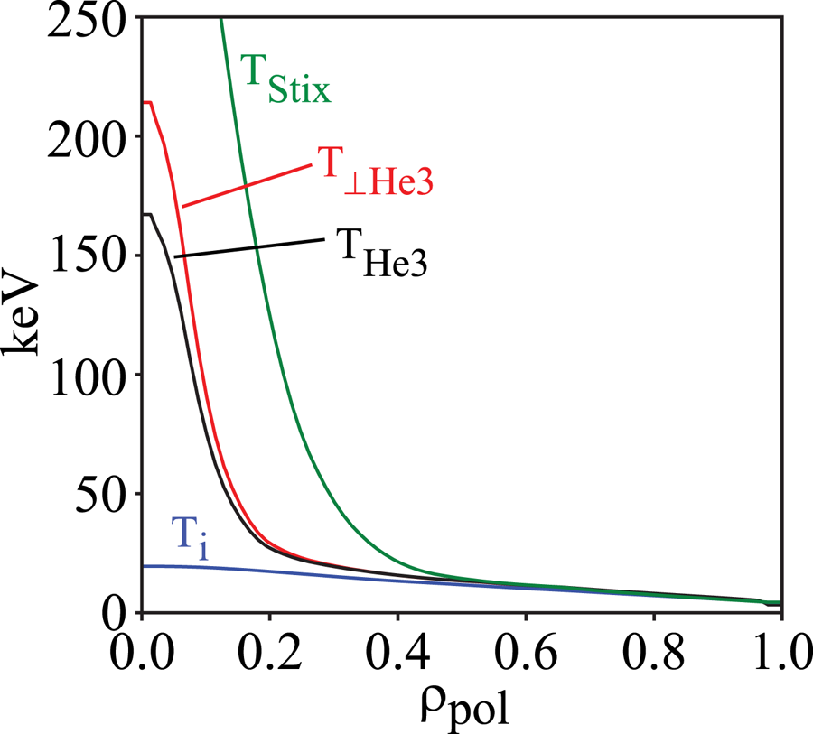
Figure 13. RF tail temperatures compared to  $T_i$ in the nominal V1E plasma. Here
  $T_{\textrm {Stix}}$ is the tail temperature computed from (9.1), and
  $T_{\textrm {He}3}$ and
  $T_{\perp \textrm {He}3}$ are the average and perpendicular tail temperature computed by TORIC, respectively.
As shown in figure 13, the nominal V1E plasma with 5 % He3 concentration heated with 11 MW of RF power achieves a central minority effective temperature of only 215 keV as computed by TRANSP, which is much less than the 3.5 MeV birth energy of the alphas. In addition, the high tail temperature is centralized in the plasma core, far from the region of significant ripple loss even for the alphas. Indeed, beyond  $\rho >0.5$ the RF ‘tail’ temperature is approximately equal to the bulk ion temperature. So, based on the computed alpha losses with a much higher birth energy, we expect ripple-induced losses of the RF tail to be negligible for the standard high-performance SPARC V1E plasma scenario. Our confidence in this expectation is tempered by the fact that the physics of alphas and RF tail ions is slightly different; alphas are born with a specific energy and then slow down collisionally, while RF tail ions are ‘born’ at their resonance location and accelerate each time they cross the resonance. Proper treatment of the RF tail ions requires an RF ‘kick’ operator, which has been implemented in ASCOT with the RFOP library (Johnson et al. Reference Johnson, Salmi, Steinbrecher, Eriksson, Hellsten, Höök, Schneider, Phillips and Wilson2011).
Going forward, we will consider a range of plasma and RF heating scenarios to develop confidence that there is not some condition, either planned or off-normal, for which a much more energetic tail is generated. Using the Stix parametric dependencies we can scale the 215 keV perpendicular tail temperature in the nominal plasma to other conditions. For example, consider an L-mode plasma that is heated with the full available RF power (25 MW) with the same power deposition profile, and with a lower He3 concentration (2 %). If the plasma density is maintained at only one third of that in the V1E plasma (which would still correspond to a central density of  $1.4 \times 10^{20}\ \textrm {m}^{-3}$) and if the central electron temperature achieved half the value in the V1E plasma, then the RF heating would drive a perpendicular tail temperature of 1.7 MeV. Even so, we expect that such an energetic tail would be localized to the plasma core and, based on the alpha simulations, ripple does not cause any losses there for the V1E coil design.
The RF fast-ion tail could be susceptible to the combined effects of ripple and MHD, as observed long ago on TFTR: the ripple in TFTR was small in the standard operating plasma regime ( $R_0/a = 2.45/80$) that was used for most DT experiments, but the edge ripple increased to 1.6 % in the large bore configuration (
 $R_0/a = 2.60/0.95$) used for RF experiments. Loss of RF tail ions in that configuration caused localized heating of vertical diagnostic ‘organ pipes’ that led to loss of vacuum during DT operations, which was attributed to the combined effects of ripple and toroidal AEs (White et al. Reference White, Goldston, Redi and Budny1998).
10 Novel fast-ion physics in SPARC
The calculations discussed above indicate that fast-ion transport and loss due to unconfined first orbits and ripple are small, which implies that SPARC should be capable of studying alpha-driven instabilities and associated alpha transport and loss. This section discusses alpha-driven MHD and associated fast-ion transport, SPARC's operating parameter space relative to these effects, and whether or not studies carried out in SPARC can provide guidance for fast-ion behaviour expected in ITER and ARC, a proposed demonstration power plant ( $R_0 = 3.3\ \textrm {m}, B_T = 9.2\ \textrm {T}$) that would put power on the grid. First, we consider the landscape of plasma self-heating physics that is achievable in SPARC at its minimum performance metric (
 $Q>2$) and at expected performance at
  $\textrm {H}98\approx 1$.
The importance of alpha particles in controlling overall tokamak behaviour is determined by the fraction of plasma power that is provided by the alpha particles:
 \begin{equation} \frac{P_\alpha}{P_{\textrm{HEAT}}} = \frac{Q}{5} ,\end{equation}
where  $P_\alpha$ is the heating power from the alphas,
  $P_{\textrm {HEAT}}$ is the power from external heating and
  $Q$ is the physics gain factor. A dominantly self-heated plasma has not been achieved to date; the closest approach occurred in the 1997 JET DT experiments, which achieved a global
  $Q=0.64$ (Keilhacker et al. Reference Keilhacker, Gibson, Gormezano, Lomas, Thomas, Watkins, Andrew, Balet, Borba and Challis1999) at which point the alphas supplied less than 13 % of the total heating power. At SPARC's
  $Q=2$ programme performance metric, 40 % of the total heating would be supplied by the alpha population. This should drive measurable electron heating and thus provide some information about possible changes in transport, but the dominant heating would remain
  $P_{\textrm {RF}}$ and so the tokamak operator would retain meaningful plasma control. Alpha particles assume a dominant role in tokamak heating starting at
  $Q \approx 5$, a value that SPARC would surpass in its baseline plasma scenario: predicted
  $Q=11$ at
  $\textrm {H}98=1.0$ (Creely et al. Reference Creely, Greenwald, Ballinger, Brunner, Canik, Doody, Fülöp, Garnier, Granetz and Gray2020) and predicted
  $Q=9$ with physics-based models (Rodriguez-Fernandez et al. Reference Rodriguez-Fernandez, Howard, Greenwald, Creely, Hughes, Wright, Holland, Lin and Sciortino2020). In this regime, the plasma would be dominantly self-heated, thus providing an opportunity to develop new plasma control techniques and to study possible thermal-excursion physics applicable to next-step devices.
Particularly at the higher  $Q$ values, the energetic particle population is expected to affect a variety of plasma phenomena in addition to self-heating. Several reviews of burning plasma physics are available, including Heidbrink (Reference Heidbrink2002), Fasoli et al. (Reference Fasoli, Gormenzano, Berk, Breizman, Briguglio, Darrow, Gorelenkov, Heidbrink, Jaun and Konovalov2007) and Chen & Zonca (Reference Chen and Zonca2016), which identify a number of important issues, including: the effect of alpha heating on bulk plasma turbulence and transport; potential sawteeth stabilization by alpha particles; potential alpha-driven excitation of collective modes including AEs; and more generally how a burning plasma self-organizes as a result of these phenomena. SPARC's capabilities to study the effect of alpha heating on plasma transport and possible sawteeth stabilization will be evaluated in a future work; here we focus on alpha-driven MHD, specifically AEs. In the next section, we outline expected trends in AE stability for SPARC, based on previous studies of the parametric dependence of AE behaviour (Gorelenkov et al. Reference Gorelenkov, Berk, Budny, Cheng, Fu, Heidbrink, Kramer, Meade and Nazikian2003; Tolman et al. Reference Tolman, Loureiro, Rodrigues, Hughes and Marmar2019). Actual computations of AE stability and mode structure will be addressed in future work.
11 Expected trends in AE behaviour
The AEs are a special form of the Alfvén wave that exists in a tokamak as an eigenmode; a comprehensive review of AE physics can be found in Heidbrink (Reference Heidbrink2008). AEs are important because they can transport energetic particles throughout the tokamak, often in synergy with other sources of energetic particle transport including ripple (White et al. Reference White, Fredrickson, Darrow, Zarnstorff, Wilson, Zweben, Hill, Chen and Fu1995), and thus AEs could play a key role in determining how a burning plasma self-organizes. Thus, various classes of AEs can be excited, each with a different typical frequency that scales with the on-axis Alfvén frequency  $f_{A0}$ (
 $\,f_{A0} \approx 700$ kHz in SPARC):
(i) beta-induced Alfvén eigenmodes (BAEs) at a low frequency below
$0.5 f_{A0}$ (Zonca, Chen & Santoro Reference Zonca, Chen and Santoro1996; Cheng et al. Reference Cheng, Podesta, Kramerand and Nazikian2019);(ii) toroidal AEs at roughly
$0.5 f_{A0}$;(iii) ellipticity-induced AEs at roughly
$1.0 f_{A0}$;(iv) noncircularity-induced AEs at
$1.5 f_{A0}$; and(v) higher frequency modes that are studied less frequently.


AEs are driven by energetic particles, which in SPARC will include alpha particles and energetic particles resulting from ICRF heating. Here, we focus on trends relating to alpha particles because these are the most novel feature of SPARC; a similar analysis could be conducted for the energetic ion tail driven by ICRF (Tolman et al. Reference Tolman, Loureiro, Rodrigues, Hughes and Marmar2019). The two most important factors affecting alpha AE drive are the ratio of the alpha particle beta,  $\beta _\alpha$, to the plasma beta,
  $\beta$, and the ratio of the on-axis Alfvén speed to the alpha particle birth velocity. We next discuss how each of these parameters affects the likely AE stability in SPARC. For the BAE, the plasma beta is also important.
Theoretical work (Fu & Van Dam Reference Fu and Van Dam1989; Betti & Freidberg Reference Betti and Freidberg1992) shows that the alpha particle contribution to the AE growth rate scales with the alpha particle  $\beta _\alpha$, while bulk ion Landau damping scales with core
  $\beta$. The ratio of these quantities determines the overall magnitude of AE drive. To estimate this value from plasma parameters,
  $\beta _\alpha$ can be estimated by balancing the alpha production rate,
  $P_\alpha \sim n^2 T^2$, against alpha thermalization time,
  $\tau _s \sim n/ T^{3/2}$ (here,
  $n$ and
  $T$ are the bulk plasma density and temperature, respectively, and we neglect the difference between the ion and electron temperatures and assume constant fuel dilution) (Tolman et al. Reference Tolman, Loureiro, Rodrigues, Hughes and Marmar2019). Then, the beta of the alpha population scales as
 \begin{equation} \frac{\beta_\alpha}{\beta} \sim \frac{\dfrac{n^2 T^2}{n/T^{3/2}}}{n T} \sim T^{5/2}. \end{equation}
The amount of AE drive is thus controlled by the bulk plasma temperature and is independent of density when neglecting resonance locations. Higher AE drive means that more modes are likely to be destabilized. In addition, some models of AE saturation predict that the saturated mode amplitude increases with linear growth rate, such that modes with higher drive will also be larger and thus more likely to drive energetic particle transport (Briguglio et al. Reference Briguglio, Schneller, Wang, Di Troia, Hayward-Schneider, Fusco, Vlad and Fogaccia2017; Todo Reference Todo2019).
To assess the relevance of studies of AE amplitude and spectrum in SPARC to expected behaviour in ITER and ARC, we compare the predicted  $\beta _{\alpha }/\beta$ based on physics-based models for SPARC to published estimates for ITER and ARC. The SPARC predictions (Rodriguez-Fernandez et al. Reference Rodriguez-Fernandez, Howard, Greenwald, Creely, Hughes, Wright, Holland, Lin and Sciortino2020) use the EPED model (Snyder et al. Reference Snyder, Groebner, Leonard, Osborne and Wilson2009) to compute the pedestal height which yields
  $Q \approx 9$ for the baseline scenario. Reduced-performance scenarios have also been evaluated by reducing the pedestal height computed by EPED; a simulation somewhat above the minimum programme objective (
 $Q \approx 3$ compared to minimum of 2) is obtained when the assumed pedestal height is reduced by 50 % at constant pedestal density (as a consequence,
  $n_{i0}$ drops 6 % and
  $T_{i0}$ drops 24 %). Table 4 compares the performance parameters for SPARC at
  $Q=3$ and
  $Q=9$ to those of inductive scenarios for ITER and ARC.
Table 4. Ratio of parameters that influence AE physics for inductive plasma scenarios in ITER and ARC to expected values in SPARC at  $Q=3$ and
  $Q=9$.
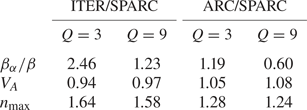
The AE drive parameter  $\beta _{\alpha }/\beta$ is significantly larger (
 $\textrm {factor} \sim 2.5$) in ITER than in SPARC at
  $Q=3$, so in that regime the AE drive will be smaller in SPARC and the relevance of AE physics studies to ITER is more limited. If SPARC achieves
  $Q=9$ performance, then its AE drive will be within 20 % of ITER's and so we would expect comparable AE behaviour. With regard to the relevance of AE studies in SPARC to expected behaviour in ARC, even at
  $Q=3$ SPARC would obtain
  $\beta _{\alpha }/\beta$ within 20 % of the value expected in ARC, and at
  $Q=9$
$Q=9$  $\beta _{\alpha }/\beta$ in SPARC would exceed that in ARC by more than 50 %.
The next parameter affecting AE behaviour is the ratio of the on-axis Alfvén speed to the characteristic energetic particle velocity. Energetic particles drive AEs when they are at velocities that resonate with the modes, which occur at locations proportional to the device Alfvén speed (Fu & Van Dam Reference Fu and Van Dam1989; Betti & Freidberg Reference Betti and Freidberg1992; Heidbrink Reference Heidbrink2008; Nabais et al. Reference Nabais, Borba, Coelho, Figueiredo, Ferreira, Loureiro and Rodrigues2015; Tolman, Catto & Loureiro Reference Tolman and Catto2020). A higher device Alfvén velocity may cut off some of these resonances, thereby reducing the AE drive (Tolman et al. Reference Tolman, Loureiro, Rodrigues, Hughes and Marmar2019). The Alfvén speed in both the  $Q=3$ and
  $Q=9$ SPARC scenarios is comparable to that in baseline ITER and ARC scenarios (within 10 %), and thus the strength of AE drive would be comparable also. Operating SPARC at lower density could push the Alfvén speed close to the alpha particle birth velocity, where a reduction of the AE drive would be observed.
Fast-ion physics including alpha redistribution by sawteeth (Farengo et al. Reference Farengo, Ferrari, Garcìa-Martìnez, Firpo and Lifschitz2013) will also be affected by the normalized gyroradius of the alphas,  $\rho ^*_\alpha = \rho _\alpha /a$, where
  $a$ is the plasma minor radius. SPARC and ARC are both smaller than ITER but have larger toroidal magnetic field, so the values of
  $\rho ^*_\alpha$ are comparable: 0.039, 0.026 and 0.025 for SPARC, ARC and ITER respectively. The toroidal mode number of the most unstable modes,
  $n_{\max }$, is another key characteristic of the AE activity, as it affects both mode transport and the diagnostic set required to observe mode activity. Assuming a normalized radial location of the mode, this parameter can be shown from theory (Fu & Cheng Reference Fu and Cheng1992; Rodrigues et al. Reference Rodrigues, Figueiredo, Ferreira, Coelho, Nabais, Borba, Loureiro, Oliver and Sharapov2015) to scale as
 \begin{equation} n_{\max} \sim \frac{R_0\varOmega_\alpha}{v_{A0}q^2}, \end{equation}
where  $R_0$ is the device major radius,
  $v_{A0}$ the on-axis Alfvén speed and
  $\varOmega _\alpha$ the alpha particle gyrofrequency. This quantity scales with device parameters as
 \begin{equation} n_{\max} \sim \frac{R_0 \sqrt{n}}{q^2}, \end{equation}
with  $n$ being the plasma density.
Because SPARC is moderately sized and has a very high density, it is likely to have AEs with toroidal mode numbers larger than those typically observed in current tokamaks, which often have lower densities and comparable or smaller sizes. Due to the large size difference between SPARC and ITER,  $n_{\max }$ would be
  ${\sim } 40$% smaller in SPARC than predicted for ITER (
 $20 \lesssim n_{\max } \lesssim 30$) (Rodrigues et al. Reference Rodrigues, Figueiredo, Ferreira, Coelho, Nabais, Borba, Loureiro, Oliver and Sharapov2015) and so the AE mode spectra would be somewhat different in the two devices.
In its baseline non-inductive (LHCD) plasma scenario, ARC is expected to operate at  $q_0 = 3.5$, and its
  $n_{\max }$ would be an order of magnitude smaller than SPARC. Thus, studies of AE activity in SPARC will not provide useful guidance about the expected AE behaviour in ARC non-inductive plasmas. In addition, the LHCD-driven current profile in ARC's non-inductive scenario has a reverse-shear region which could lead to RSAEs (Heidbrink Reference Heidbrink2008) that would be absent in SPARC. However, an inductive plasma scenario has also been defined for ARC that achieves
  $P_{\textrm {fus}} > 500$ MW with
  $H_{98} = 1$. The ARC parameters reported in table 4 pertain to the inductive plasma scenario. At both
  $Q=3$ and
  $Q=9$, SPARC's
  $n_{\max }$ is within 20–25 % of the value expected in ARC, and thus similar AE behaviour is expected in the two devices.
For BAEs, the value of the plasma beta also affects the stability threshold. Theoretical treatments (Zonca et al. Reference Zonca, Chen and Santoro1996) suggest that the size of the gap in which BAEs can exist increases with plasma beta. Experimental studies (Heidbrink et al. Reference Heidbrink, Strait, Chu and Turnbull1993) confirm the appearance of BAEs at high beta. SPARC is expected to operate at low beta ( $\beta _N = 1.0, \beta = 0.012$), compared to non-inductive ARC (
 $\beta _N=2.59$,
  $\beta = 0.019$) and inductive ITER (
 $\beta _N = 1.8, \beta = 0.025$), suggesting that BAE activity is less likely in SPARC than in ITER or the non-inductive ARC. While this is a favourable trend for alpha confinement in SPARC, it suggests that SPARC may struggle to provide an understanding of BAE physics that is pertinent to ARC and ITER.
12 Conclusion
First-orbit and ripple-induced losses of the alpha population have been computed for the baseline SPARC V1E TF coil design for its baseline full performance ( $I_p, B_T$, DT, sawtoothing H-mode)
  $Q \approx 10$ plasma scenario. Assuming perfectly aligned TF coils, the ripple-induced alpha power loss (0.25 %) is small compared to the first-orbit loss (2.8 %) and the computed surface heating is acceptably small (
 $244\ \textrm {W}\ \textrm {m}^{-2}$) on limiter surfaces. The surface power densities on the RF antennas are reduced by a large factor (
 $\sim 40$) if they are recessed just 1 cm from the neighbouring protective limiters. Because the RF tail temperature is small in the baseline scenario, we also expect negligible ripple-induced power losses of the RF tail population.
The assembled TF coil set will be subject to misalignments in various directions, which increases the ripple and the ripple-induced losses. For a given magnitude of misalignment, offsets in the toroidal direction and in/out offsets generate the most ripple and the most ripple-induced losses. Coil misalignments increase the total alpha power lost and also cause the lost power to become more concentrated toroidally and poloidally, leading to significant increases in surface heating power density. A final recommendation for the maximum allowable coil misalignment must await future calculations of the lost-alpha power for an optimized wall shape, but the results discussed here suggest that localized surface heating may become problematic for coil misalignments having a normal distribution with  $\sigma = 0.7\text {--}1.8$ cm.
The alpha losses were computed by two different simulation codes, ASCOT and SPIRAL, which are found to yield very similar results not only in the integrated power losses, but also for the spatial, temporal and pitch-angle dependence of the losses. This provides some confidence that the codes correctly model the orbit physics.
When operated at minimum performance, SPARC would provide an opportunity to begin studies of plasma self-heating, and at  $\textrm {H}98\approx 1$, SPARC would enter a dominantly self-heated regime (
 $Q=9\text {--}11$), which would enable studies of thermal excursion issues and plasma control techniques. At moderate
  $Q=3$, AE physics studies in SPARC would be only marginally informative with respect to expected AE behaviour in ITER. At
  $Q=9$, there is a reasonably good overlap between the AE parameters in SPARC and ITER, the main limitation being the difference in mode spectrum. At both
  $Q=3$ and
  $Q=9$ the AE parameters are quite similar between SPARC and ARC, and thus studies of AE physics in SPARC would be relevant to the behaviour expected in ARC.
Acknowledgements
This work was funded by Commonwealth Fusion Systems under RPP005. G.J.G. was funded under the INFUSE programme – a DOE SC FES private private–public partnership programme, grant No. 2702. E.A.T. was supported by the National Science Foundation Graduate Research Fellowship under grant no. 1122374. This study used resources of the National Energy Research Scientific Computing Center (NERSC), a US Department of Energy Office of Science User Facility operated under contract no. DE-AC02-05CH11231. We are grateful to the ASCOT development team for their development and maintenance of the ASCOT code and for technical support. A.S. was supported by the Academy of Finland (grant no. 324759). S.D.S thanks R. Scott of Analysis Group, Boston, for discussions of the statistical uncertainty in power loss fractions.
Editor William Dorland thanks the referees for their advice in evaluating this article.
Declaration of interests
The authors report no conflict of interest.
Appendix
This appendix compares some software implementation details between the ASCOT and SPIRAL orbit-simulation codes. Both codes include necessary physics to study neoclassical transport of fast ions during slowing down but the models are different. Both ASCOT and SPIRAL can model the full gyromotion orbit (GO), and ASCOT can also compute the (much faster but less accurate) guiding centre (GC) trajectory. In ASCOT, the gyromotion is solved using the ‘volume-preserving algorithm’ (VPA) (Zhang et al. Reference Zhang, Liu, Qin, Wang, He and Sun2015), which is essentially a relativistic variant of the better-known energy-preserving Boris method (which in turn is essentially a modified Leap-Frog method). SPIRAL uses the Adams method implemented via the NAG library. VPA is a fixed time-set-up method, whereas the Adams method seems to be adaptive so the latter is potentially faster. For the GC simulations, ASCOT uses the relativistic Hamiltonian formalism (Tao, Chan & Brizard Reference Tao, Chan and Brizard2007) (up to first order) and solves the equations of motion with either the fixed-step Runge–Kutta 4 or adaptive Cash–Karp method (table 5).
Table 5. Major features of ASCOT and SPIRAL orbit simulation codes.
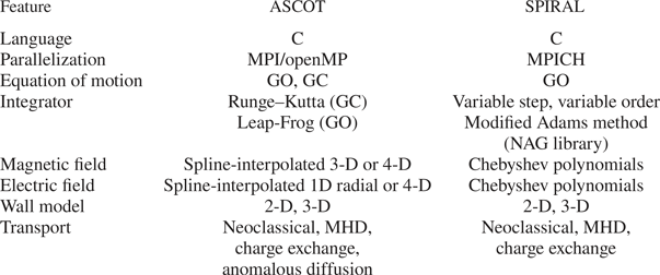
There is a difference between the codes on how collisions are included. SPIRAL calculates the pitch collision frequency and the slowing-down rate. At each time step, the marker energy is reduced deterministically in accordance with the local slowing-down rate and the pitch is randomly increased or decreased in accordance with the pitch collision frequency. ASCOT uses the Landau collision operator for particle momentum vector (Helander & Sigmar Reference Helander and Sigmar2002) (or to be more precise, the corresponding Langevin equation). For the GCs, ASCOT uses its GC-transformed and gyro-averaged variant (Brizard Reference Brizard2004).
The practical difference is that ASCOT includes also the diffusion/stochastic term in energy. Therefore, the particle energy cannot reach zero as in SPIRAL, as the fast ions eventually form a Maxwellian distribution in energy. However, this does not matter since the simulation in both codes is terminated at the moment a particle is considered to belong to the thermal bulk. There might be some minor ‘up-scattering’ in energy in ASCOT due to this but the difference to SPIRAL is not significant for alphas. In both codes there are no collisions between the markers themselves and the background plasma is assumed to be static.
We have verified that, in a uniform plasma, ASCOT produces the same slowing-down rate as the one SPIRAL computer. So, even though the collision models are different, both are based on established physics and the little difference they have should not be significant for alpha simulations. There are no physics (relevant for these SPARC slowing-down studies) in one code that would be missing from the other. Therefore, these codes are suitable for verifying that there has not been an error in the orbit-following calculations.


 Open access