Investigation on Shear Capacity of Joints between Steel Reinforced Concrete Special-Shaped Column and Reinforced Concrete Beam
 Ping Xiang1,2,3,5 Yipeng Lin1 Wei Huang1 Faxing Ding1,4 Bailong Ye1 Zhiheng Deng3*
- 1School of Civil Engineering, Central South University, Changsha, China
- 2Key Laboratory of Ministry of Education for Geomechanics and Embankment Engineering, Hohai University, Nanjing, China
- 3College of Civil Engineering and Architecture, Guangxi University, Nanning, China
- 4National Engineering Laboratory for High-Speed Railway Construction, Changsha, China
- 5Guangdong Provincial Key Laboratory of Building Energy Efficiency and Application Technologies, Guangzhou, China
Steel reinforced concrete (SRC) special-shaped column structures have all properties of steel reinforced structures and special-shaped column structures. The design of SRC special-shaped column joints is of great importance to ensure that this structure can be widely used in earthquake-prone areas. This research adopts a new joint design style, and a pseudo-static test is carried out on three joints (JD-1, JD-2, and JD-3) between the SRC special-shaped column and the RC beam, and one joint (JD-4) between the RC special-shaped column and concrete beam. The working mechanism of joints and the function of steel in the shear resistance mechanism are analyzed. Based on the results of experimental research, this article presents formulas on the cracking capacity and shear resistance capacity of these joints with theoretical and applicative purposes. Taking into account all these facts, the high resistance capacity and reliability of the joint design method are manifested. Some conclusions derived from this research can be used as a reference for engineering practice.
Introduction
Comparing steel reinforced concrete (SRC) and normal RC, the SRC column structure has more advantages due to its high strength (Chen et al., 2020; He et al., 2019) and shear capacity (Xu et al., 2019; Jiang and Bai, 2020; Zhao, 2020). In recent decades, the SRC structure has been attracting the attention of engineering circles and is being generally promoted in the construction of high structures around the world (Wang et al., 2020). Because the shape of traditional frame columns is usually rectangle, it always shows the edges in the four corners of the rooms with small bay, like residence and office (Chen et al., 2016). Traditional frame construction columns directly influence the view, the arrangement of furniture, and the appearance of the structure, and are not available for use. This is one of the main reasons why the application range of frame construction is restricted. To solve this problem, engineering circles began to introduce the special-shaped column, which means the column section is not the conventional rectangular section (Liu et al., 2016). In order to meet the requirements in strength and stiffness, we can use different column section forms, including L-section, cross section, T-section, and Z-section, based on the room layout and the position needs of the column (Chen et al., 2006). Because the width of the special-shaped columns is the same as that of masonry walls, the special-shaped columns can help in the better use of available space, improve the esthetic appearance of a structure, and have good building functions (Chen et al., 2017). SRC special-shaped (SRCSS) column has all the properties of an SRC structure and special-shaped column structure. The bearing capacity of this structure is very good with excellent applicable quality, and the structure is pleasing to the eye. Therefore, it is an excellent structure form that deserves to be promoted and studied. Nowadays, some experiments and researches on SRC structures (Chen et al., 2020) and SRC-RC column joints (Li et al., 2019) are being conducted. But, there are still few experimental and research results relevant to SRCSS column joints, especially on the shear performances in the joint core areas.
Xue et al. (2012) performed an experimental study to investigate the seismic performance of SRCSS columns with a total of 17 SRCSS column specimens under low-cyclic reversed load tests. Two models of two-bay and three-story frame, including an edge frame and a middle frame, were designed and tested by Liu et al. (2014), and it was found that the failure mechanism of a solid SRC frame with special-shaped columns is the beam-hinged mechanism, satisfying the seismic design principle of “strong column and weak beam.” Chen et al. (2015) further investigated the hysteretic behavior of special-shaped columns composed of SRC, and an axial compression ratio limit value for SRCSS columns was proposed (Chen et al., 2016). Based on shaking table experiments for a five-floor SRC spatial frame with special-shaped columns, the translational response, torsional response, and translational-torsional response were analyzed by Zhou et al. (2020). Composed action and loading were also considered in the investigation of SRC structures (Feng et al., 2019). The mechanical performance of structures is largely determined by material properties of microscale to macroscale materials (Yao et al., 2016; Yao et al., 2017; Yao et al., 2018; Yao et al., 2019; Deng et al., 2020). Simulation and tests show that the capacities of the structure can be improved by forming a composite structure with different materials (Yao et al., 2015; Yao et al., 2016; Yao and You, 2016; Yao and You, 2017; Deng et al., 2020). For example, a steel truss is composed of a concrete beam to show enhanced mechanical performances (Deng et al., 2020), bearing capacity, and seismic performances of joints (Deng et al., 2018). Investigation of shear walls with steel truss coupling beams under seismic loading also shows that the hysteretic behavior is obviously improved (Deng et al., 2018). Moreover, it is also reported that in SRC, the ductility, capacity of energy dissipation, stiffness degradation, and reliability of elements’ area are satisfactory (Jiang et al., 2018; Feng et al., 2020), and the joint generally performs well under seismic action (Chen et al., 2015; Xu et al., 2015; Xiang et al., 2017).
This research focuses on the shear performance of the joints between the SRCSS columns and the RC beams under bidirectional low-cyclic reversed loading. Bidirectional low-cyclic reversed loading means applying low-cyclic reversed loading on both sides of a beam simultaneously for the joints that connect RC beams with SRCSS columns in two directions. A total of four specimens have been designed and tested, among which three were the joints between SRCSS column and RC beam specimens, and one was the joint of a RC special-shaped column and a RC beam specimen. The design of those specimens was based on the reinforcement ratio of the stirrup in the special-shaped column, and those results were compared in the test. In this research, a design form of SRCSS column–RC beam joints is proposed, the working mechanism of joints and impact factors are analyzed, and the calculation formula for predicting the crack resistance and shear capacity of SRCSS column–RC beam joints is suggested.
Experimental Design
For experimental studies on the shear behavior of joints, joint specimens with single beam side were used in many previous tests. But in this test, joint specimens with two beam sides for bidirectional low-cyclic reversed loading were used to better simulate the stress state of corner joints in space under bidirectional earthquake action.
Specimen Size and Reinforcement
A total of four specimens were designed and manufactured in this experiment to simulate the stress state of corner joints in space under bidirectional earthquake action. In this test, there were four specimens: JD-1, JD-2, JD-3, and JD-4. Each specimen was connected with two beams and two special-shaped columns. The core area of a joint was the intersection between beams and columns. For distinction, these two beams were named beam-1 and beam-2, respectively, in this test. The distance between the loading point and the outer wall section of the special-shaped column was 1.3 m in beam-1. The distance between the loading point and the outer wall section of the special-shaped column was 1.2 m in beam-2. The different distances between the loading point and the outer wall section of the special-shaped column reflected the difference between the vertical and horizontal spans of a frame under bidirectional earthquake action. It also reflected that the distance between the inflection point and the outer wall of the special-shaped column was different. So this test can reflect the actual situation better. Each specimen took the reinforcement ratio of the stirrup in the core area of the joint as the running parameter. The design of the specimens shall ensure that the column ends that the specimen is linked with will not be destroyed first, before the shear failure of the core area. The designed size of the section and the selection of reinforcement can be seen in Table 1. The three-dimensional drawing of RC beam specimens is shown in Figure 1. The dimension and reinforcement of a column section are shown Figures 2 and 3.
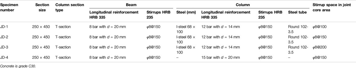
TABLE 1. Details of specimens.
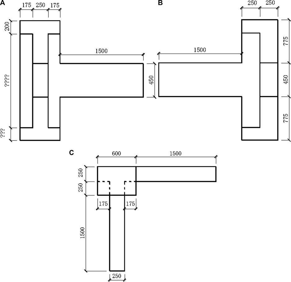
FIGURE 1. Three-dimensional drawings of specimens. (A) Front elevation drawing, (B) left-side drawing, and (C) planar drawing.
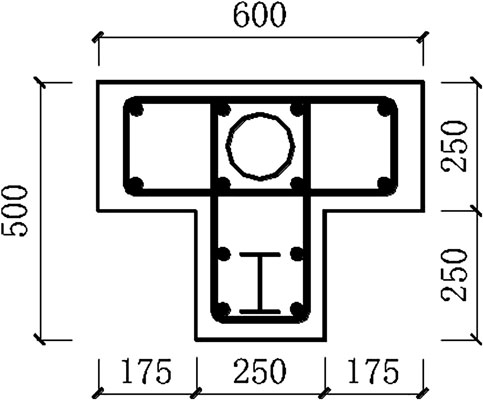
FIGURE 2. Dimension of the column section of specimens JD-1, JD-2, and JD-3.
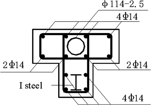
FIGURE 3. Reinforcement of the column section of specimens JD-1, JD-2, and JD-3.
For easy loading, each specimen was designed with rectangular column capitals. The vertical and horizontal sides of the column capital were, respectively, arranged with a dense row of reinforcing mesh with a diameter of 12@60 and 12@80 to ensure that the force of the column capital is transferred reasonably to the column. The reinforcement is shown in Figure 4.
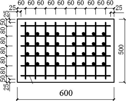
FIGURE 4. Reinforcement of column capital.
According to the calculation, both the top and the bottom of the beam in the test were reinforced with four HRB 335 reinforcing bars with a diameter of 20 mm to ensure that the load at the end of the beam and the joint failure were in the range of loading values of a servo-actuator loading control system, as shown in Figures 5–7. The reinforcements of the specimens are shown in Figure 8.
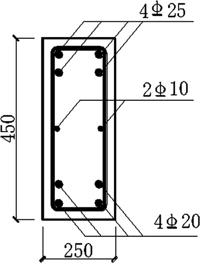
FIGURE 5. Reinforcement of the beam section of specimens JD-1, JD-2, and JD-3.
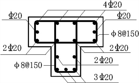
FIGURE 6. Reinforcement of specimen JD-4.
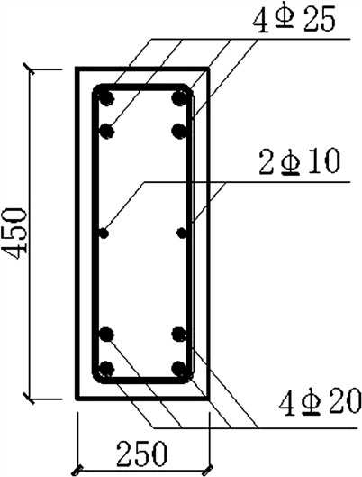
FIGURE 7. Reinforcement of the beam section of specimen JD-4.
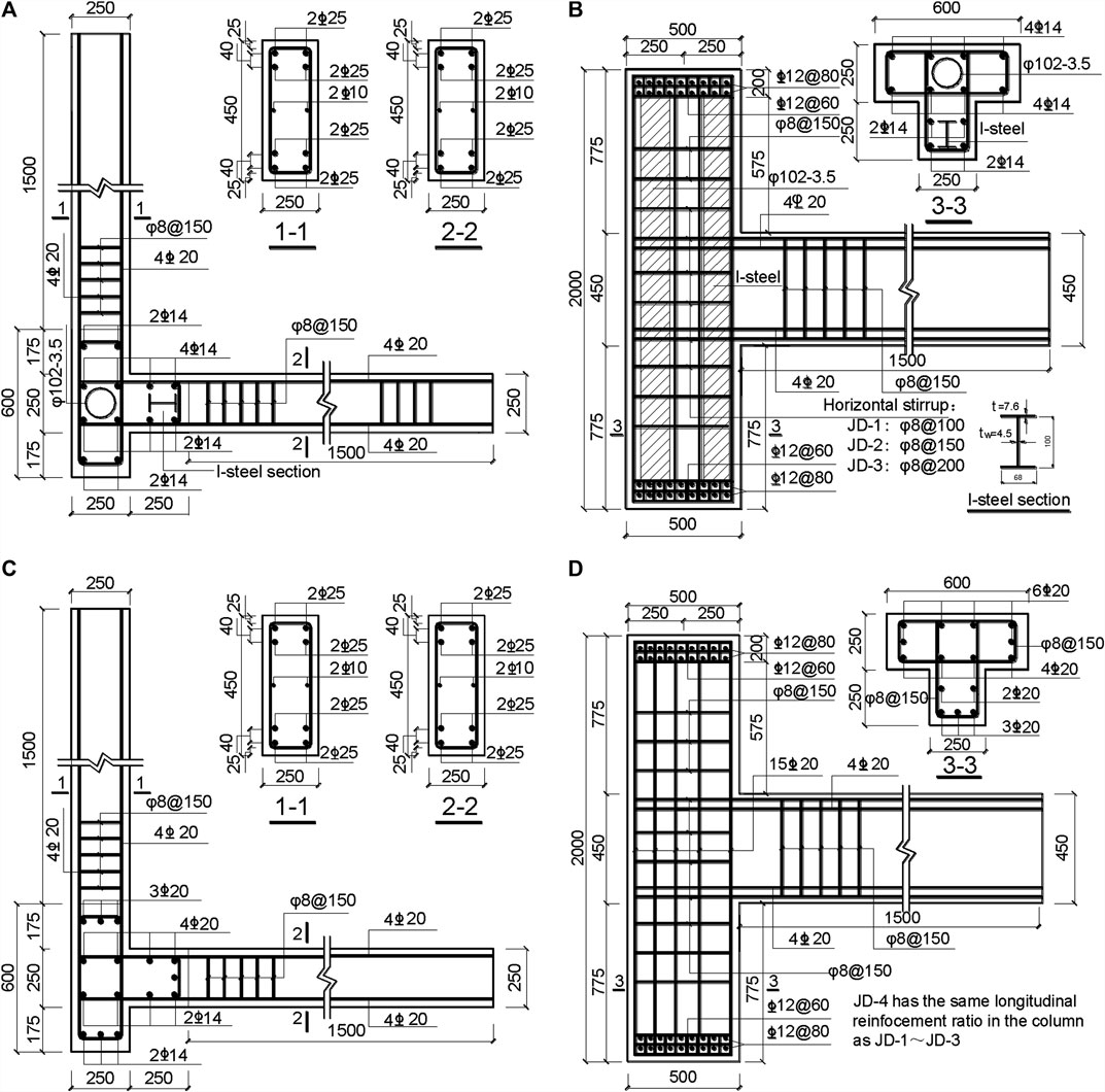
FIGURE 8. Details of specimens. (A) Section reinforcement of specimens JD-1, JD-2, and JD-3; (B) reinforcement of specimens JD-1, JD-2, and JD-3; (C) section reinforcement of specimen JD-4; and (D) section reinforcement of specimen JD-4 (Xiang et al., 2017).
Mechanical Properties of Materials
All specimens with C30 grade concrete were maintained for 28 days according to the regulations. Three standard cube blocks (150 mm × 150 mm × 150 mm) were maintained when the specimens were poured to determine the mechanical properties of concrete. In order to ensure the concrete strength of the specimens was the same as that of the remaining test blocks, the test blocks and specimens were maintained in open air under the same conditions. Besides, the cube strength of the test block should be measured on the day when the specimen is to be tested. Sixty concrete strain gauges and steel strain gauges were affixed to each specimen, which were arranged on the crack-prone part of the concrete in the joint area, the longitudinal reinforcing bars in the beam, stirrups, and steel bars.
When the concrete was poured and the steel bars were bound, a small portion was reserved to measure the actual mechanical properties of the material. The measurement results are provided in Tables 2 and 3.
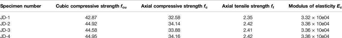
TABLE 2. Mechanical properties of concrete (N/mm2).
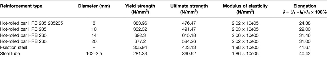
TABLE 3. Mechanical properties of steel tube, profile steel, and bars.
Loading Device and Loading System
The pseudo-static test was carried out on three joints between the SRCSS column and the RC beam specimens JD-1, JD-2, and JD-3, and one joint between the RC special-shaped column and the specimen JD-4. Meanwhile, their performances under bidirectional low-cyclic reversed loading were compared. By changing the reinforcement ratio of stirrups in the core areas of the SRCSS column and RC beam, the regular parameter of influence was obtained. An electro-hydraulic servo structure test machine was used for repeated bidirectional low-cyclic loading in the test. The test loading device is shown in Figure 9. By using the pseudo-static test method, in order to ensure that the specimen can move freely in the horizontal direction under vertical load and horizontal load, a free-sliding hinge device was arranged between the hydraulic jack and the upper rigid beam to which the vertical load is applied at the top of the column.
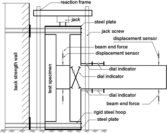
FIGURE 9. Drawing of loading devices (Xiang et al., 2017).
For the most accurate and effective simulation of two-way seismic action, the loading system made the core area to be in the most unfavorable state. The low-cyclic reversed gradual loading system was used at the bidirectional ends of the beam in the test.
Periodical loading means repeated loading according to a certain force or displacement periodicity. The low-cyclic reversed loading was adopted in the test, which had hierarchical hybrid control on the force and displacement. A photograph of the loading device is presented in Figure 10.
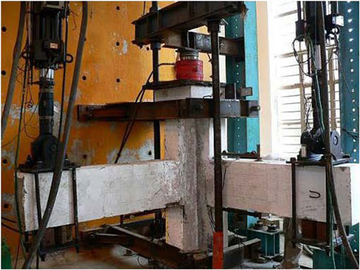
FIGURE 10. Picture of loading devices (Xiang et al., 2017).
Axial Force
For the choice of axial force, there are axial forces and no axial forces under different conditions. The specimen JD-1 was tested under the condition of no axial force. The remaining three specimens were applied with axial force at the top of the column and loaded with an oil jack.
Axial load should be applied first, and the value of axial load should be stable when repeated test loads are applied. The method of geometric alignment was used to make the axial load act on the center of the special-shaped section. Then, all the scheduled load values should be applied two to three times. The axial loads of the four specimens are JD-1 without axial compression, 1,000 kN of JD-1’s axial pressure, 800 kN of JD-1’s axial pressure, and 800 kN of JD-1’s axial pressure, applied by an oil jack at the top of the column.
Low-Cyclic Reversed Loading
The hybrid control loading system that can control load and displacement was adopted in the loading procedure. This system was divided into two stages, as shown in Figure 11.
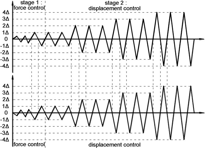
FIGURE 11. Loading rule (Xiang et al., 2017).
The First Stage: Load Control Stage
Load control was used at the small deformation stage before the specimen reached the yield load, and the value, which is 0.75 times the calculated yield load value, was taken as the back load control point. Load started until beam-1 was loaded down to the load classification control point, and at the same time, beam-2 was loaded up to the load classification control point. Reading was done once after stabilization and repeated according to this rule. After one loading cycle, it was loaded to yield and then entered the displacement control stage.
The Second Stage: Displacement Control Stage
When the specimen had a critical diagonal crack (after yield), the displacement control was adopted. The yield of the specimen is marked by an obvious turning point in the P−Δ relation. The loading was controlled by using the multiple of the yield displacement value of the specimen with critical diagonal cracks, and each displacement level was recycled three times. The sign at the end of the test was that the specimen was completely destroyed when the specimen reached the maximum bearing capacity and dropped to 85% of the maximum load.
In order to eliminate the influence of test installation or other factors and check whether the measurement instrument response was normal or not, the axial load was repeated three times at 50% of its value and then loaded to full value. For the same reason, the cracking load was repeated two times at 50% of its value, and then the loading was continued before the formal test.
Stress Mechanism of Joints
After the frame was subjected to external loads, the stress in the core area was calculated and is shown in Figure 12. There were bending moments M1 and M2, and shear forces V1 and V2 around the core area passing through the beam. Meanwhile, it was also subjected to axial force N, bending moment MC, and shear force VC coming from the top of the column. These load effects were distributed and transferred within the joints to make the core area play its role. According to the stress process and failure types of joints, the distribution and transmission of these effects can be accurately described, and reasonable theoretical assumptions and calculation models can be given. This is the stress mechanism of the joint. The stress mechanism of joints is affected by various factors, including concrete strength, properties of steel, reinforcement structures in joints, and the anchorage of beams and columns. So far, the common mechanisms of joints are the strut mechanism, the shear friction mechanism, and the truss mechanism.
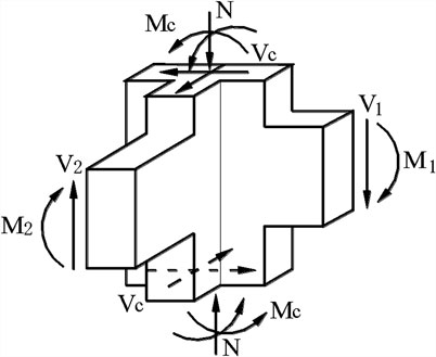
FIGURE 12. Stress mechanism of joints.
The structure mechanism and the shear friction mechanism will be used in the further analysis. The truss mechanism is applicable when the core zone is equipped with both horizontal stirrups and dense vertical reinforcement and when the joints are subjected to a large shear force, and a plurality of cracks are generated in the core area under repeated loading. Under the above conditions, the effect of the diagonal concrete struts was reduced, and most of the shear forces could be assumed by an imaginary truss mechanism. In this test, the SRC was prepared in the core area of the joint, and there were few longitudinal steel bars in the special-shaped column. It was difficult to form a dense steel mesh frame in the core area of the joint during the failure process. In fact, it was not a separate function of a certain force-receiving mechanism in the shearing process in the core area of the joint, but it worked under the combined actions of various force transmission mechanisms. Although the sources of various force transmission mechanisms are very clear in theory, it is still impossible to quantify the shear forces shared by various force transmission mechanisms. Therefore, in the subsequent analysis, it is necessary to grasp the characteristics of the forces in the different stress processes of the nodes. It is also necessary to select the dominant force mechanism and the force model for analysis.
Shear Capacity of Space Joints
As for the shear capacity of space joints, according to the literature (Xue et al., 2012), when the crack resistance and shear strength of a two-way space frame joint are calculated, the unidirectional crack resistance and shear strength of two main axes can be calculated separately in advance, and then the synthetic shear strength can be obtained by the force synthesis principle. The calculation formula is as follows:
where
As for the design of the space joints and the calculation of the shear capacity, it is usually based on the analysis of the unidirectional force at different principal directions.
Theoretical Analysis of the Crack Resistance Capacity of Joints
At the beginning of the loading, the beam–column joints were basically in the elastic state, and the shear deformation of the steel web was basically the same as that of concrete. As the load continued to increase, the concrete cracked along the diagonal of the joint core. As the load continued to increase, concrete cracks in the core area increased and expanded, and the shear deformation increased. Force analysis is conducted in the direction of the joint, and a joint core was selected for element analysis, as shown in Figure 13.
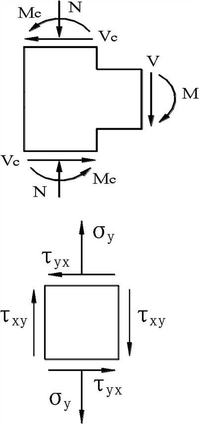
FIGURE 13. Stress state of joint core.
The shear deformation of a joint is analyzed as follows:
where
where
where
Therefore, the shear strain is R when the joint is initially cracked. At this time, there is strain coordination in the joint area.
Then,
According to strain coordination in the joint area:
Then,
where
α is the influence coefficient of concrete axial tensile strength (it is related to the axial compression ratio and can be obtained from test data); and ft is the standard value of concrete axial tensile strength.
The anti-crack bearing capacity in the core part of the joint between the SRCSS column and the RC beam was formed by superimposing the steel, the concrete in the core area, the steel tube, and the concrete in the steel tube. The calculation formula is as follows:
where
bi, hi are the width and height of the cross section of the joint core, respectively;hw, tw are the height and thickness of the steel web, respectively; and
D, t are the nominal diameter and wall thickness of the joint steel tube, respectively.
According to the results of the test, we can measure the relation between the shear stress
This test can determine the values of k1 and k2 according to the SRCSS column and RC beam joint specimens JD-1 and JD-2. The axis pressure of specimen JD-1 is 0; the axis pressure of specimen JD-2 is 1,000 kN; the cracking load in the core area of joint JD-1 is 70 kN; and the cracking load in the core area of joint JD-2 is 110 kN. After substituting them into Eq. 4, the results are k1 = 0.71 and k2 = 1.457, and we can get the formula as follows:
The relation curve
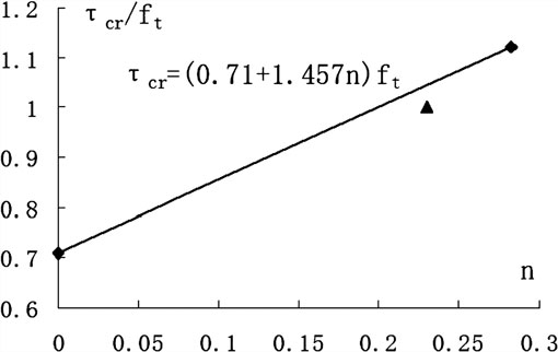
FIGURE 14.
The crack resistance capacity of 102 kN when the axial pressure is 800 kN is calculated by the formula, which is in good agreement with the actual cracking load 98 kN of test piece JD-3. As shown in Figure 14, the triangle icon point represents the measured value of the SRCSS column joint specimen JD-3 tested at an axial pressure of 800 kN. It can be seen from the figure that it is very close to the calculated value of the formula.
When the main crack was formed, the concrete along the diagonal of the core area formed a through crack, and the steel web and the core steel tube also entered the yield stage. The stress of the stirrups also increased significantly, or even yielded. At this time, the effective work of stirrups and steel webs had a certain restraining effect on the concrete in the core area. Therefore, the ordinary concrete in the core area was subjected to a part of shear force and still had a certain contribution to the shear capacity of the joint. Even after the steel tube and the steel web were yielded, the bearing capacity of the joint could be improved, but the shear deformation of the core area would be obviously increased. Before the steel reached the limit state with the appropriate steel, the steel and steel tubes would yield. The joint test showed that the shear capacity of the special-shaped column joints with steels and core steel tubes was mainly provided by the concrete in the joint core, the stirrups, and the steel concrete and core steel tube concrete in the joint core. Due to the restraining effect of steel profiles, especially steel tubes, the shear bearing capacity of concrete significantly increased. In the presence of axial pressure, the large axial compression ratio made the cracking load of the joint increase greatly. The existence of axial pressure also made the ultimate load energy increase considerably. In a certain range, the greater the axial compression ratio is, the more the cracking shear force and the ultimate shear force will be.
This work analyzed the force mechanism of spatial joints and proposed the formula for calculating the anti-crack and shear capacity of RC beams and RC special-shaped columns. The shear capacity of SRCSS column joints was obviously better than that of normal RC special-shaped column joints. The webs and concrete of the built-in steels contributed a lot to the shear resistance of the joints. The stirrups in the joint area also bore part of the shear force. The shear resistance of the joint was formed by the shear capacity of the concrete, the shear capacity of the stirrups in the joint area, the shear capacity of the steel web, and the shear capacity of the concrete in the steel tube. In this article, the influence of axial compression ratio on the shear capacity of the joint was also analyzed, and the important conclusion that the shear capacity of the joint increases along with an increase of the axial compression ratio within a certain range was obtained.
Conclusion
The bidirectional low-cyclic reversed loading test on the RC beam joints and the SRCSS columns in this article can put the joint in a more unfavorable and real stress state in service. It is much closer to the general case of the structural joints under the actual two-way earthquake action than the conventional single-beam joint test of the side-column joint of frame structure. The test results have a higher realistic reference value. From the test results obtained in this article and the theoretical analysis, the following conclusions are obtained:
1. SRCSS columns and RC beams have small stiffness degradation, good ductility, and less degradation in bearing capacity, which can meet the design requirements of strong joints between strong columns and weak beams. So it is suitable for application and promotion. However, there are still some limitations in the application of SRCSS structures because some relevant specifications have not been published, for example, under eccentric compression and torsion, which need to be further studied.
2. The existence of axial compression ratio may increase the cracking load and shear capacity of the joint. The axial compression ratio adds a direction constraint to the core area of the joint. But the axial compression ratio shall be controlled within a certain range to play a positive role. Otherwise, it will have an adverse effect on the joint.
3. Steel web can effectively bear part of the shear force. The shear capacity of joints with steel is larger than that of normal concrete joints, and the ductility is better. The steel flange has a certain restraining effect on the concrete, so that the crack resistance and shear resistance of the concrete are improved to some extent. Meanwhile, the concrete in the joint area has a certain restraining effect on the steel web under the effective work of the stirrups, which can prevent local buckling of the steel web.
4. The shear capacity of a concrete-filled steel tube in the core region of beam–column joints of SRCSS columns is not a simple superposition of the shear strength about steel and concrete. Due to the restraining effect of steel tubes, the shear resistance of concrete in the joint core is about 50% better than that of normal concrete. Concrete is evenly stressed in the steel tube. When plastic hinge failure occurs at the beam end, the hysteresis loop is full and shows a shuttle shape. It indicates that the core concrete in the steel tube has good energy dissipation and ductility when participating in the resistance of shear force in the joint core area.
5. According to theoretical analysis, the shear capacity of the joints between RC beams and SRCSS columns is mainly composed of the shear capacity of steel webs, the shear capacity of concrete in the joint core, and the shear capacities of the stirrups and the core concrete in steel tubes.
Data Availability Statement
The raw data supporting the conclusions of this article will be made available by the authors, without undue reservation.
Author Contributions
PX and YL wrote the article, WH and FD helped in the research, BY helped in the theoretical analysis, and ZD is the project leader.
Funding
This work is supported by grants from the National Natural Science Foundation of China (Grant Nos. 11972379, 51268005, and 51908263), Guangxi Natural Science Foundation (Grant No. 2013GXNSFAA019311), Double-class fund from Central South University (Grant No. 502045006), Key Laboratory of Ministry of Education for Geomechanics and Embankment Engineering, Hohai University and Guangdong Provincial Key Laboratory of Building Energy Efficiency and Application Technologies. The findings and opinions expressed in this article are only those of the authors and do not necessarily reflect the views of the sponsors.
Conflict of Interest
The authors declare that the research was conducted in the absence of any commercial or financial relationships that could be construed as a potential conflict of interest.
Acknowledgments
The authors greatly appreciate the editors and referees for spending time in attentively reading and checking this article.
References
Chen, Z. P., Jing, C. G., Xu, J. J., and Zhang, X. G. (2017). Seismic performance of recycled concrete-filled square steel tube columns. Earthq. Eng. Eng. Vib. 16, 119–130. doi:10.1007/s11803-017-0372-2
Chen, Z. P., Xu, J. J., Chen, Y. L., Xue, and J. Y. (2015a). Seismic behavior of steel reinforced concrete (SRC) T-shaped column-beam planar and 3D hybrid joints under cyclic loads. Earthq. Struct. 8, 555–572. doi:10.12989/eas.2015.8.3.555
Chen, Z. P., Xu, J. J., and Xue, J. Y. (2015b). Hysteretic behavior of special shaped columns composed of steel and reinforced concrete (SRC). Earthq. Eng. Eng. Vib. 14, 329–345. doi:10.1007/s11803-015-0026-1
Chen, Z. P., Xu, J. J., Chen, Y. L., and Xue, J. Y. (2016). Axial compression ratio limit values for steel reinforced concrete (SRC) special shaped columns. Steel Compos. Struct. 20, 295–316. doi:10.12989/scs.2016.20.2.295
Chen, Z. P., Zhao, H. T., Xue, J. Y., and Xv, A. B. (2006). Research on bearing capacity of steel reinforced concrete special-shaped columns. Adv. Struct. Eng. Theory Appl. 2, 143–148.
Chen, Z. P., Zhou, J., Ban, M. G., and Wang, X. Y. (2020a). Residual bond behavior of steel reinforced recycled aggregate concrete after exposure to elevated temperatures. Front. Mater. 7, article 142. doi:10.3389/fmats.2020.00142
Chen, Z. P., Zhou, J., Li, Z. B., Wang, X. Y., and Zhou, X. Y. (2020b). Seismic behavior of concrete-filled circular steel tubular column-reinforced concrete beam frames with recycled aggregate concrete. Appl. Sci. 10, 2609.
Deng, Z. H., Hu, Q., Zeng, J., Xiang, P., and Xu, C. C. (2018a). Structural performance of steel-truss-reinforced composite joints under cyclic loading. Proc. Inst. Civil Eng. Struct. Build. 171, 130–148. doi:10.1680/jstbu.16.00188
Deng, Z. H., Xu, C. C., Hu, Q., Zeng, J., and Xiang, P. (2018b). Investigation on the structural behavior of shear walls with steel truss coupling beams under seismic loading. Adv. Mater. Sci. Eng. 2018, 5602348. doi:10.1155/2018/5602348
Deng, Z. H., Huang, H. Q., Ye, B. L., Wang, H. P., and Xiang, P. (2020a). Investigation on recycled aggregate concretes exposed to high temperature by biaxial compressive tests. Construct. Build. Mater. 244, 118048. doi:10.1016/j.conbuildmat.2020.118048
Deng, Z. H., Huang, H. Q., Ye, B. L., Xiang, P., and Li, C. Q. (2020b). Mechanical performance of RAC under true-triaxial compression after high temperatures. J. Mater. Civ. Eng. 32. doi:10.1061/(asce)mt.1943-5533.0003231
Deng, Z. H., Liu, B., Ye, B. L., and Xiang, P. (2020c). Mechanical behavior and constitutive relationship of the three types of recycled coarse aggregate concrete based on standard classification. J. Mater. Cycles Waste Manag. 22, 30–45. doi:10.1007/s10163-019-00922-5
Feng, Y., Jiang, L.-z., Zhou, W.-B., and Han, J.-P. (2019). Lateral–torsional buckling of box beam with corrugated steel webs. J. Cent. South Univ. 26, 1946–1957. doi:10.1007/s11771-019-4122-0
Feng, Y. L., Jiang, L. Z., and Zhou, W. B. (2020). Improved analytical method to investigate the dynamic characteristics of composite box beam with corrugated webs. Int. J. Steel Struct. 20, 194–206. doi:10.1007/s13296-019-00278-4
He, L. S., Lin, S. Q., and Jiang, H. J. (2019). Confinement effect of concrete-filled steel tube columns with infill concrete of different strength grades. Front. Mater. 6, 71. doi:10.3389/fmats.2019.00071
Jiang, L. J., and Bai, G. L. (2020). Experimental study on cumulative damage behavior of steel-reinforced concrete columns. Adv. Civ. Eng. 2020, 5281725.
Jiang, L. Z., Feng, Y. L., Zhou, W. B., and He, B. B. (2018). Analysis on natural vibration characteristics of steel-concrete composite truss beam. Steel Compos. Struct. 26, 79–87.
Li, Z. B., Liu, Y. S., Ma, H., Wang, Q. Q., and Tang, Z. Y. (2019). Seismic performance of full-scale joints composed by concrete-filled steel tube column and reinforced concrete beam with steel plate-stud connections. Adv. Civ. Eng. 2019, 5476909. doi:10.1155/2019/5476909
Liu, Z. Q., Xue, J. Y., and Zhao, H. T. (2016). Seismic behavior of steel reinforced concrete special-shaped column-beam joints. Earthq. Struct. 11, 665–680. doi:10.12989/eas.2016.11.4.665
Liu, Z. Q., Xue, J. Y., Zhao, H. T., and Gao, L. (2014). Cyclic test for solid steel reinforced concrete frames with special-shaped columns. Earthq. Struct. 7, 317–331. doi:10.12989/eas.2014.7.3.317
Wang, P., Shi, Q. X., Wang, F., and Guo, S. S. (2020). Damage assessment of an SRC frame-core tube structure under the action of a main aftershock sequence. Adv. Civ. Eng. 2020, 1308530.
Xiang, P., Deng, Z. H., Su, Y. S., Wang, H. P., and Wan, Y. F. (2017). Experimental investigation on joints between steel-reinforced concrete T-shaped column and reinforced concrete beam under bidirectional low-cyclic reversed loading. Adv. Struct. Eng. 20, 446–460. doi:10.1177/1369433216653841
Xu, C. X., Sheng, P. S., and Wan, C. C. (2019). Experimental and theoretical research on shear strength of seismic-damaged SRC frame columns strengthened with enveloped steel jackets. Adv. Civ. Eng. 2019, 6401730. doi:10.1155/2019/6401730
Xu, J. J., Chen, Z. P., Chen, Y. L., and Xue, J. Y. (2015). Earthquake damage evaluation of T-shaped SRC composite column-steel beams in 3D connection joints. Adv. Struct. Eng. 18, 701–713. doi:10.1260/1369-4332.18.5.701
Xue, J. Y., Chen, Z. P., Zhao, H. T., Gao, L., and Liu, Z. Q. (2012). Shear mechanism and bearing capacity calculation on steel reinforced concrete special-shaped columns. Steel Compos. Struct. 13, 473–487. doi:10.12989/scs.2012.13.5.473
Yao, H., Dai, Q. L., and You, Z. P. (2015). Chemo-physical analysis and molecular dynamics (MD) simulation of moisture susceptibility of nano hydrated lime modified asphalt mixtures. Construct. Build. Mater. 101, 536–547. doi:10.1016/j.conbuildmat.2015
Yao, H., Dai, Q. L., and You, Z. P. (2016a). Molecular dynamics simulation of physicochemical properties of the asphalt model. Fuel 164, 83–93. doi:10.1016/j.fuel.2015.09.045
Yao, H., Dai, Q. L., You, Z. P., Bick, A., and Wang, M. (2018). Modulus simulation of asphalt binder models using Molecular Dynamics (MD) method. Construct. Build. Mater. 162, 430–441. doi:10.1016/j.conbuildmat.2017.09.106
Yao, H., Dai, Q. L., You, Z. P., Bick, A., Wang, M., and Guo, S. C. (2017). Property analysis of exfoliated graphite nanoplatelets modified asphalt model using molecular dynamics (MD) method. Appl. Sci. 7, 43.
Yao, H., Dai, Q. L., You, Z. P., Ye, M. X., and Yap, Y. K. (2016b). Rheological properties, low-temperature cracking resistance, and optical performance of exfoliated graphite nanoplatelets modified asphalt binder. Construct. Build. Mater. 113, 988–996. doi:10.1016/j.conbuildmat.2016.03.152
Yao, H., Dai, Q. L., You, Z. P., Zhang, J. X., Lv, S. T., and Xiao, X. H. (2019). Evaluation of contact angle between asphalt binders and aggregates using Molecular Dynamics (MD) method. Construct. Build. Mater. 212, 727–736. doi:10.1016/j.conbuildmat.2019.03.283
Yao, H., and You, Z. (2017). Performance of micro- and nano-modified asphalt mixtures through flow number and moisture susceptibility evaluations. J. Test. Eval. 45, 2009–2019. doi:10.1520/jte20150434
Yao, H., and You, Z. P. (2016). Effectiveness of micro- and nanomaterials in asphalt mixtures through dynamic modulus and rutting tests. J. Nanomater. 2016, 2645250. doi:10.1155/2016/2645250
Zhao, T. F. (2020). Bearing capacity studies on square steel tube confined steel reinforced concrete column under eccentric load. Adv. Civ. Eng. 2020, 4212049.
Keywords: steel reinforced concrete, special-shaped column, joint, low-cyclic reversed loading, shear resistance capacity
Citation: Xiang P, Lin Y, Huang W, Ding F, Ye B and Deng Z (2020) Investigation on Shear Capacity of Joints between Steel Reinforced Concrete Special-Shaped Column and Reinforced Concrete Beam. Front. Mater. 7:588296. doi: 10.3389/fmats.2020.588296
Received: 28 July 2020; Accepted: 24 August 2020;
Published: 28 September 2020.
Edited by:
Hui Yao, Beijing University of Technology, ChinaCopyright © 2020 Xiang, Lin, Huang, Ding, Ye and Deng. This is an open-access article distributed under the terms of the Creative Commons Attribution License (CC BY). The use, distribution or reproduction in other forums is permitted, provided the original author(s) and the copyright owner(s) are credited and that the original publication in this journal is cited, in accordance with accepted academic practice. No use, distribution or reproduction is permitted which does not comply with these terms.
*Correspondence: Ping Xiang, pxiang2-c@my.cityu.edu.hk, pxiang@csu.edu.cn, 909859894@qq.com