1. Introduction
This paper describes efforts by the University of Alaska Fairbanks (UAF) under the Federal Aviation Administration (FAA)/NASA Unmanned Aircraft Systems (UAS) Traffic Management (UTM) program to safely integrate UAS into the US National Airspace System (NAS). It details the flight campaigns of UAF’s Alaska Center for Unmanned Aircraft Systems Integration (ACUASI), an FAA UAS Test Site, in supporting the program goals and objectives. The paper outlines UAF’s flight campaign activities, demonstration results, and continuing efforts in support of the UTM program and long-term Beyond Visual Line-Of-Sight (BVLOS) operations necessary for conduct of arctic research and public service missions in Alaska.
The remainder of this section examines the popularity of UAS, some economic drivers behind this trend, and the need to smartly regulate the integration of UAS activities within the NAS.
Section 2, Materials and Methods, details UAF’s participation in the UTM program through Technical Capability Level (TCL) phases 1–3.
Section 3, Discussion, highlights results of the flight campaigns, technical achievements, and lessons learned.
Section 4, Conclusions, outlines ongoing efforts and future work needed to advance UAF’s BVLOS capabilities in the remote Alaskan environment. The
Appendix A includes a comprehensive list of acronyms, excerpts from the NASA Statements of Work (SoW), and list of references.
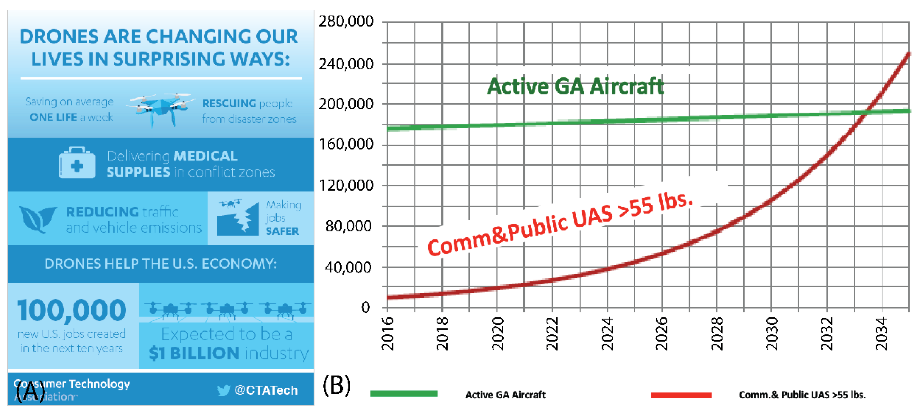
Background: The US and the world have seen a dramatic rise in popularity and application of Unmanned Aircraft Systems (UAS) in recent years. UAS of many sizes, shapes, and characteristics are being flown in unprecedented numbers and applications today. Like many other technological advances that consumers interact with on a daily basis, UAS, aka Unmanned Aerial Vehicles (UAV), or “drones”, applications are expanding daily. UAS initially were expensive and of limited utility to the general public, but recent technological improvements and market forces as shown in
Figure 1A, have resulted in a virtual explosion in the availability of complex and affordable UAS capable of satisfying a wide spectrum of mission sets and operating requirements [
1] (p. 5).
A 2020 survey of over 1000 participants showed that 15% of Americans have flown a drone, and 8% own at least one [
2] (pp. 1–3). This shows the increasing interest in UAS by hobbyists, but the need for UAS technology is increasingly being noticed by the commercial sector as well. UAS are now applicable to a multitude of sectors including media, real estate, disaster response, mining, maritime, education, construction, tourism, utilities, agriculture, meteorology, aviation, and logistics including the experimentation of home delivery by large logistical companies such as Amazon, UPS, and Google [
3] (p. 2). This technology is now so highly in demand that the number of UAS over 55 pounds is expected to surpass the number of active GA (General Aviation) aircrafts in less than 15 years as seen in
Figure 1B [
4] (p. 8).
Figure 1.
(
A) Impact of the Unmanned Aircraft Systems (UAS) industry © 2018, CTA™ [
5] (p. 4) and (
B) Federal Aviation Administration (FAA) prediction of General Aviation (GA) UAS over 55 lbs. © 2018, CTA™ [
4] (p. 8).
Figure 1.
(
A) Impact of the Unmanned Aircraft Systems (UAS) industry © 2018, CTA™ [
5] (p. 4) and (
B) Federal Aviation Administration (FAA) prediction of General Aviation (GA) UAS over 55 lbs. © 2018, CTA™ [
4] (p. 8).
Integrating UAS into the NAS: Although technological advancements regarding UAS and their popularity are both on the rise [
6] (p. 1), there are other barriers slowing UAS growth potential, including Federal Aviation Administration (FAA) regulations, public acceptance, and national/state infrastructure [
7] (p. 2). One of the largest barriers in growing the UAS-based economy sector today is the need to responsibly and safely integrate UAS into the National Airspace System (NAS). While UAS have been in existence for over a century, integration of these aircraft for civilian purposes into the NAS has not yet been established, as the UAS flight is still too unique to completely adopt General Aviation’s (GA’s) current system. The need for regulations specifically governing the use of small UAS under 55 lbs. has been highly voiced, but at present does not match the technical capability and popularity of today’s systems.
While there is universal recognition that safety is paramount in this effort, many criticize that the FAA has been overly cautious due to a lack of policy differentiating drones and their abilities. For example, current FAA policy treats a hobbyist drone the same as emergency services UAS [
7] (p. 15). The balance between safety and growth has many stakeholders frustrated as technology leaps ahead, while the legal ability to utilize that technology lags behind. Every year that UAS integration into the NAS is unavailable, the US loses more than
$10 billion amounting to
$27.6 million per day of potential economic impact lost [
8] (p. 2). In addition, stakeholders are calling for comprehensive legislature that would define responsibilities and liabilities in case of accidents so they may balance risk and reward and ensure that insurance and financial firms are able to support the UAS market because without safe protocols there will be no support for the market [
9] (p. 3).
UAS flight regulations, the scope of the issue, and the potential consequences cannot be taken lightly. In 2012, there were an estimated 200,000 h of domestic UAS operations and that figure was predicted to be at over a million hours in 2020 [
10] (p. 17). In 2016, the FAA started a registration system to understand how many UAS there are in the US. Within the first month of opening the registration site there were nearly 300,000 UAS owners that registered their vehicles [
3] (p. 2). In 2018 more than 175,000 new commercial UAS were registered, increasing the number in the US by more than 170% and expanding the total commercial market to 277,000 units. This far exceeded the 44% of growth that had been expected for the year [
11] (p. 1).
In the same report, the FAA predicted there would be around 452,000 commercial UAS in use by 2022, but that number was already reached by the beginning of March 2020 [
12] (p. 1 and 9). Based on the latest data the FAA now expects there to be 835,000 commercial UAS by 2023, which would mean a tripling of the market over five years [
11] (p. 1). Experts also claim that 350,000 UAS pilots will be registered by 2023. As of May 2019, there were roughly 1.25 million amateur UAS in the US and that is expected to increase to 1.4 million by 2023 [
11] (p. 2). Most recently, the FAA reports that as of 10 March 2020, a total of 1,563,263 UAS have been registered (441,709 commercial UAS and 1,117,900 recreational UAS) and 171,744 remote pilots have been certified [
12] (p. 1). Furthermore, the FAA predicts that air traffic will continue to increase 1% per year for the next 21 years [
13] (p. 27).
FAA/NASA UAS Traffic Management Program: In response to the need for safely integrating UAS into the US National Airspace System, the FAA, in conjunction with NASA, implemented a joint program to manage this effort. The program, titled the UAS Traffic Management (UTM) system, was led via a FAA/NASA Research Transition Team (RTT). NASA took primary lead for the initial program with a series of flight campaigns focused on identifying and developing suitable technologies, tools, and procedures that would eventually allow Small UAS (sUAS) to operate safely within the NAS. The FAA focused on operationalizing the most promising technologies, tools, and procedures to develop more realistic planning scenarios and concepts of operation for implementation or further study.
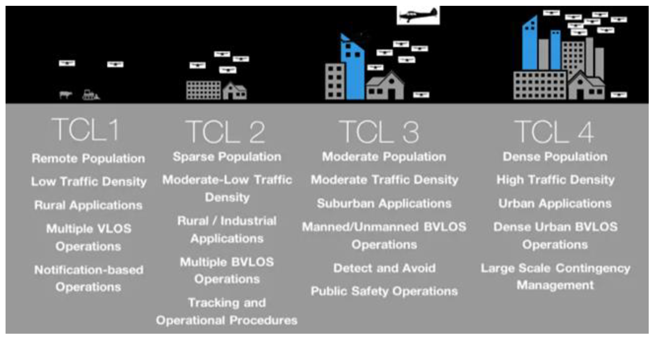
NASA UTM campaigns were named according to increasingly [
14] (p. 1) complex Technical Capability Levels (TCLs) shown in
Figure 2, moving from initial demonstrations of low-density UAS operations in sparsely populated rural areas (TCL1) and incrementally moving towards high-density, highly interactive scenarios requiring increased levels of UAS autonomy and system integration (TCL4).
The FAA UTM flight campaigns, titled the UTM Pilot Program (UPP) provided realistic scenarios for expected UAS/manned aircraft operations to determine the appropriate next steps toward the development and deployment of prototype enterprise services into the FAA framework [
16] (p. 1). “UTM services demonstrated in UPP Phase One included: (1) the exchange of flight intent among operators, (2) the generation of notifications to UAS Operators regarding air and ground activities, known as UAS Volume Reservations (UVRs), and (3) the ability to share UVRs with stakeholders, including other UAS Service Suppliers (USS) and the Flight Information Management System (FIMS)”. UPP2 objectives include testing of Remote Identification (RID) technologies and operations with increasing volumes and density in cooperation with NASA, FAA UAS Test Sites, industry stakeholders, and UAS IPP participants [
17] (p. 1).
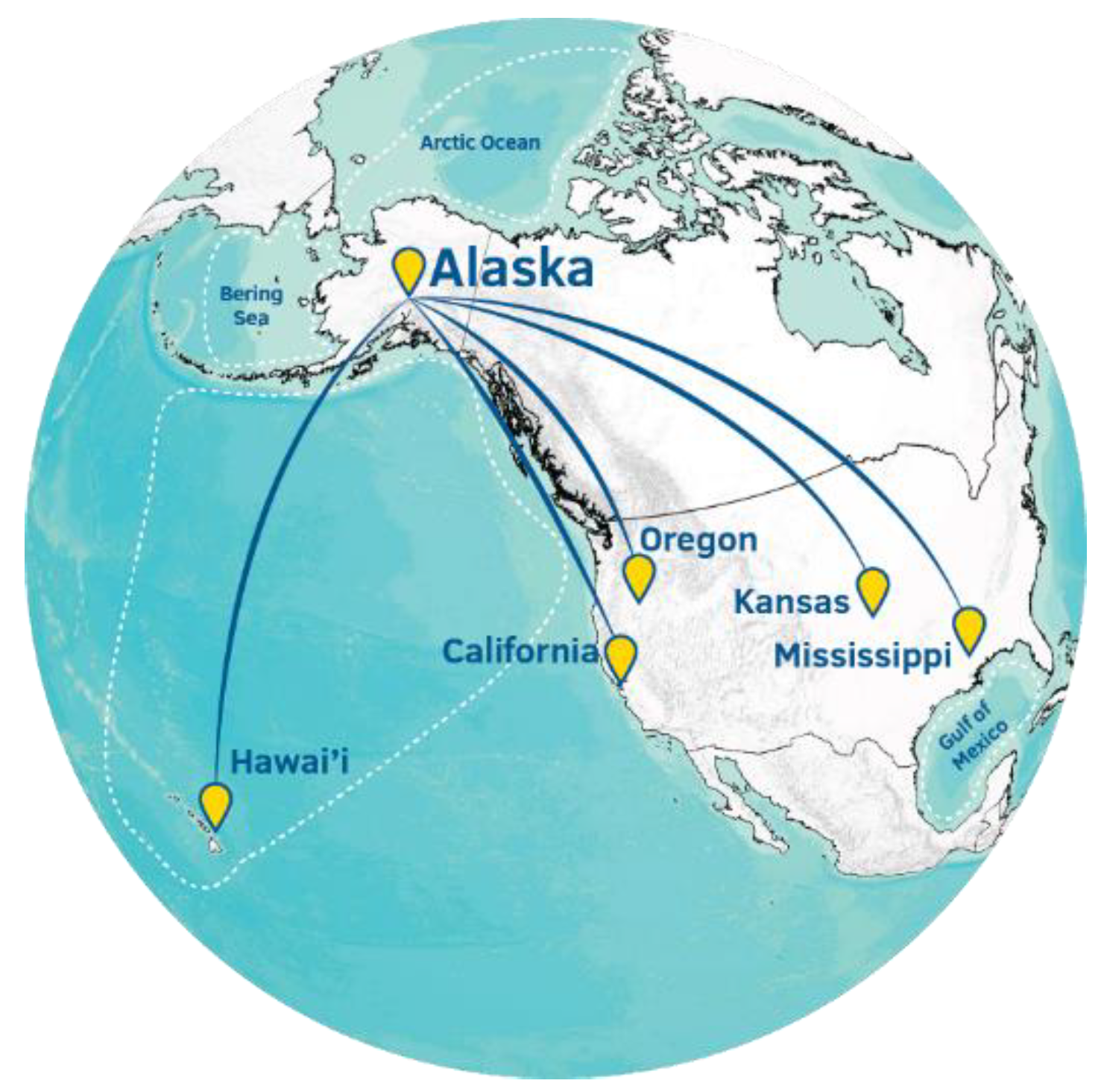
UAF organizational interest in UTM: In December 2013, UAF’s Alaska Center for Unmanned Aircraft Systems Integration (ACUASI) was selected as one of the six FAA UAS test sites established by the 2012 FAA Modernization and Reform Act. The Pan Pacific UAS Test Range Complex (PPUTRC) reports to ACUASI, but also includes principal partners in Oregon and Hawaii as well as 56 non-state partners located across US and internationally.
Figure 3 shows locations of the PPUTRC major ranges and partners.
In May 2018, UAF was named as one of the 10 Integration Pilot Program (IPP) teams by the Department of Transportation (DoT) and Federal Aviation Administration (FAA). The team’s 21 partners include UAS manufacturers, technology developers, operators and public and private end users from Alaska and the rest of the US. The team’s charter focuses primarily on monitoring pipelines, roads and other linear infrastructure, and also includes areas such as delivering medical devices to remote areas, helping search and rescue (SAR) efforts, and surveying fish and wildlife. In support of these missions, UAF has been granted authority by the FAA to conduct true BVLOS operations. UAF was selected for UTM participation and to support the development, design, and testing of the TCL1, TCL2, and TCL3 campaigns. This paper describes the UTM program goals and accomplishments integrating UAS into NAS in Western US accomplished by the ACUASI team.
2. Materials and Methods
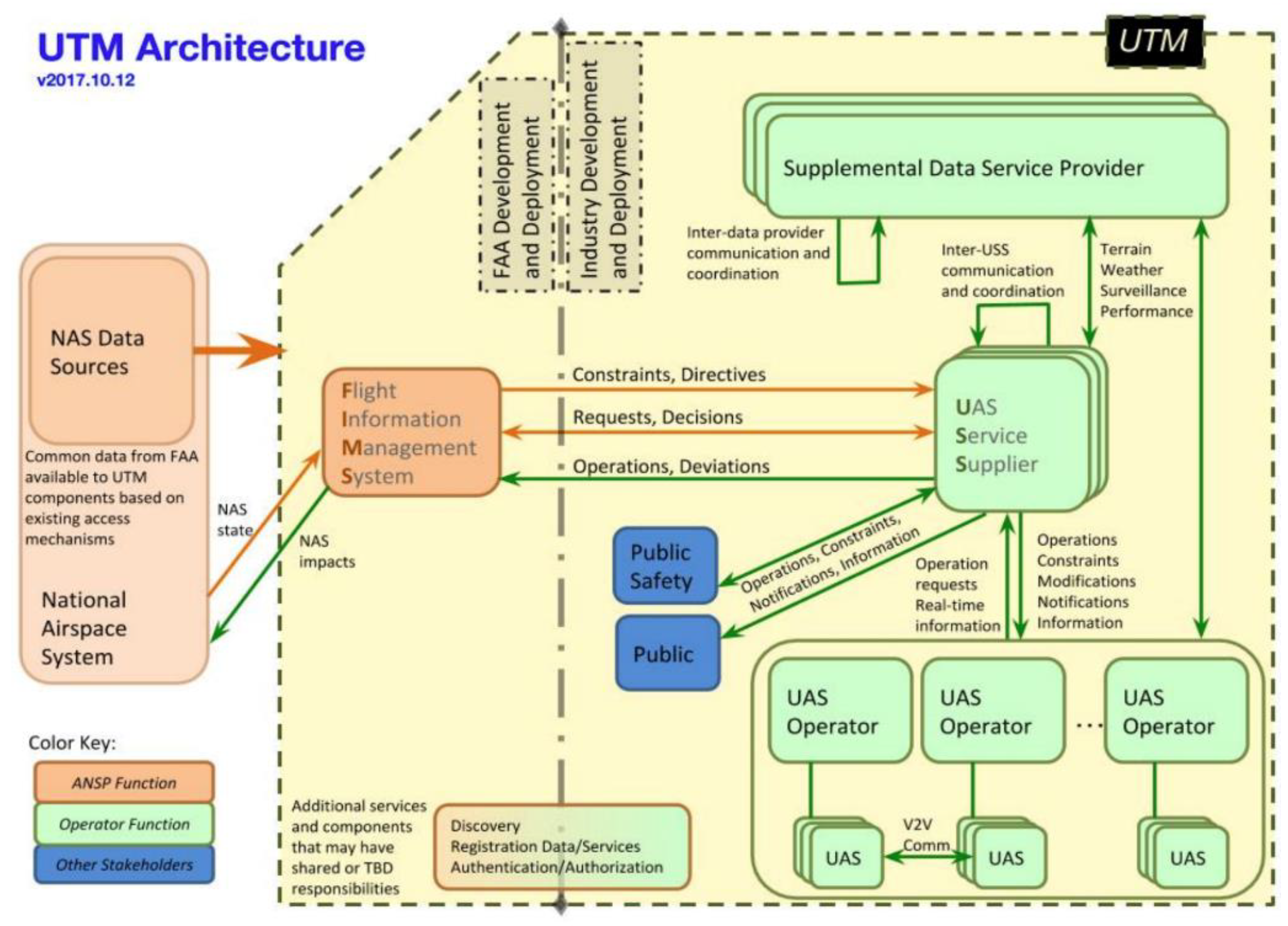
The UTM system architecture shown in
Figure 4 highlights the major components needed to fly a particular mission within airspace reserved for this purpose, including local volume or multiple legs of a Beyond Visual Line-Of-Sight (BVLOS) route, the UAS operator, the UAS Service Supplier (USS), Supplemental Data Service Provider (SDSP), and the Flight Management Information System (FIMS). The UAS operator is responsible for requesting airspace volumes and times, operating the UAS safely and within the parameters governing the UAS within this airspace, recording the times of takeoff/landing, and noting any remarkable or abnormal events during the flight (e.g., incursion of other UAS or aircraft into the airspace and inflight emergencies).
The USS serves as the primary link between the UAS operator and the central FIMS, forwarding airspace requests and UAS position information to the FIMS and returning airspace request status, emergency notifications, and other airspace picture information to the UAS operator. The SDSP provides an additional layer of information for some missions, such as local weather and terrain data. The FIMS is the central core of the UTM system, responsible for maintaining the overall air picture, deconflicting missions, approving/modifying airspace, tracking UAS flights, and advising USS providers of high-priority UAS or manned aircraft missions.
The UTM system provides for two levels of data portals into UAS operations, accessible at the USS provider level. The public portal allows the general public to visualize generic information on the UAS flying in the local area or other locations. The public safety portal allows public safety officers access to additional information about the UAS missions (e.g., owner and contact information). USS providers may communicate via the FIMS and relay a request for information regarding UAS under the control of other USS providers.
In examining a conceptual overview of how the UTM elements might interact in support of a typical mission,
Figure 5, multiple USS providers are located throughout an area in support of various UAS operators and are in constant communication with both their UAS operators and the centralized FIMS. In addition, the USS providers are registered within a centralized USS Discovery Service and may be made aware of one another for the purposes of resolving emerging airspace issues (e.g., incursion of a UAS from its approved airspace into another airspace due to vehicle malfunction or extreme weather).
Table 1 summarizes UAF/ACUASI’s participation in the UTM program. Campaigns were primarily performed at UAF’s main campus and the Poker Flat Research Range (PFRR). TCL2a was a centralized effort performed under NASA’s supervision at Reno-Stead Airport in Nevada. UAS employed were all in the small UAS (sUAS) category (under 55 lbs.), and all were either single rotor (ING Responder) or multirotor UAS, with the exception of the Aeromao Aeromapper fixed-wing UAS utilized in TCL1. UAS were selected for the missions based on their ability to support mission objectives, flexibility in performing various roles, reliability/availability of parts, ease of use, and cost.
A central tenet in UAF’s strategy for the UTM program has been to work in areas that will both benefit NASA/FAA and those mission sets and capabilities in which the test site is vested. As such, the team focused efforts on increased support for Beyond-Visual-Line-of-Sight (BVLOS) flights in high-latitude locations, such as is common in Alaska. This includes systems enabling improved navigation and long-range communications, as well as tools supporting multiple simultaneous UAS operations and increased ability to operate in cooperation with geofences. Through this and related efforts, UAF achieved a majority of the initial technical and operational goals outlined in the mission sets.
UTM TCL1 campaign: Using the crawl, walk, run approach, testing began with relatively sparse UAS operations in either remote or lightly populated urban areas. The basic requirements for this phase included the ability for a UAS crew to request and reserve a defined volume of airspace, for the UAS to be capable of reporting its position to NASA, for mission durations to be tracked, and for the system status of UAS to be logged (ready, airborne, rogue, landed, and mission terminated). The interface for communications was provided through a UAS System Services (USS) provider. Selected excerpts from the NASA TCL1 Statement of Work (SoW) are provided in
Appendix A.
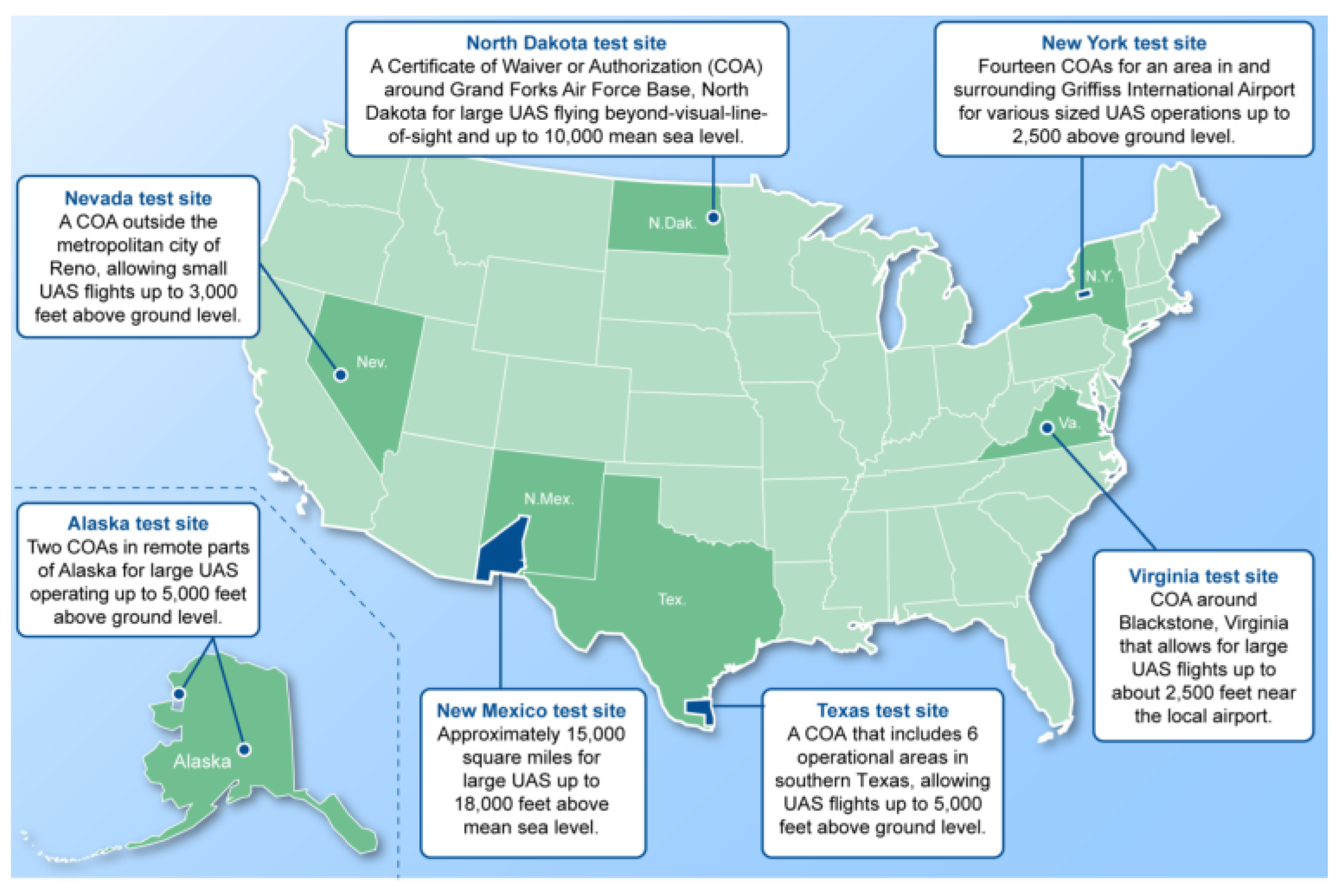
The UTM TCL1 campaign and flight demonstration occurred in May/June 2016. The overarching focus for this effort was to demonstrate the ability for the UTM system to support coordination with UAS operators located across the country and to simultaneously track these geographically diverse operations. All six participating FAA UAS test sites (Alaska, Nevada, Texas, North Dakota, Virginia, and New York),
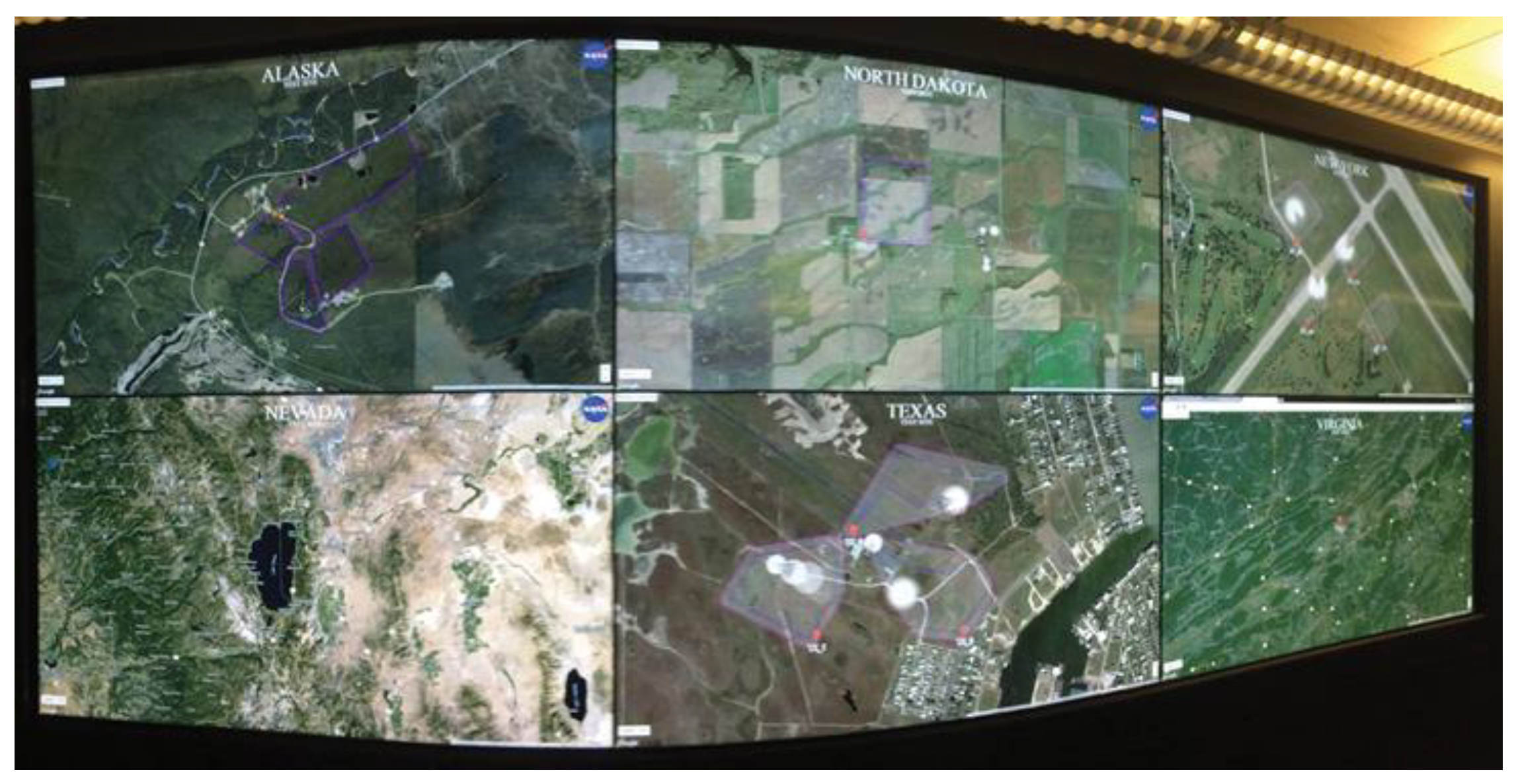
Figure 6, each flew four UAS, for a total of 24 UAS simultaneously flown across the country. The flight paths of all UAS were depicted in real-time at the NASA Ames Research Center UTM program office,
Figure 7.
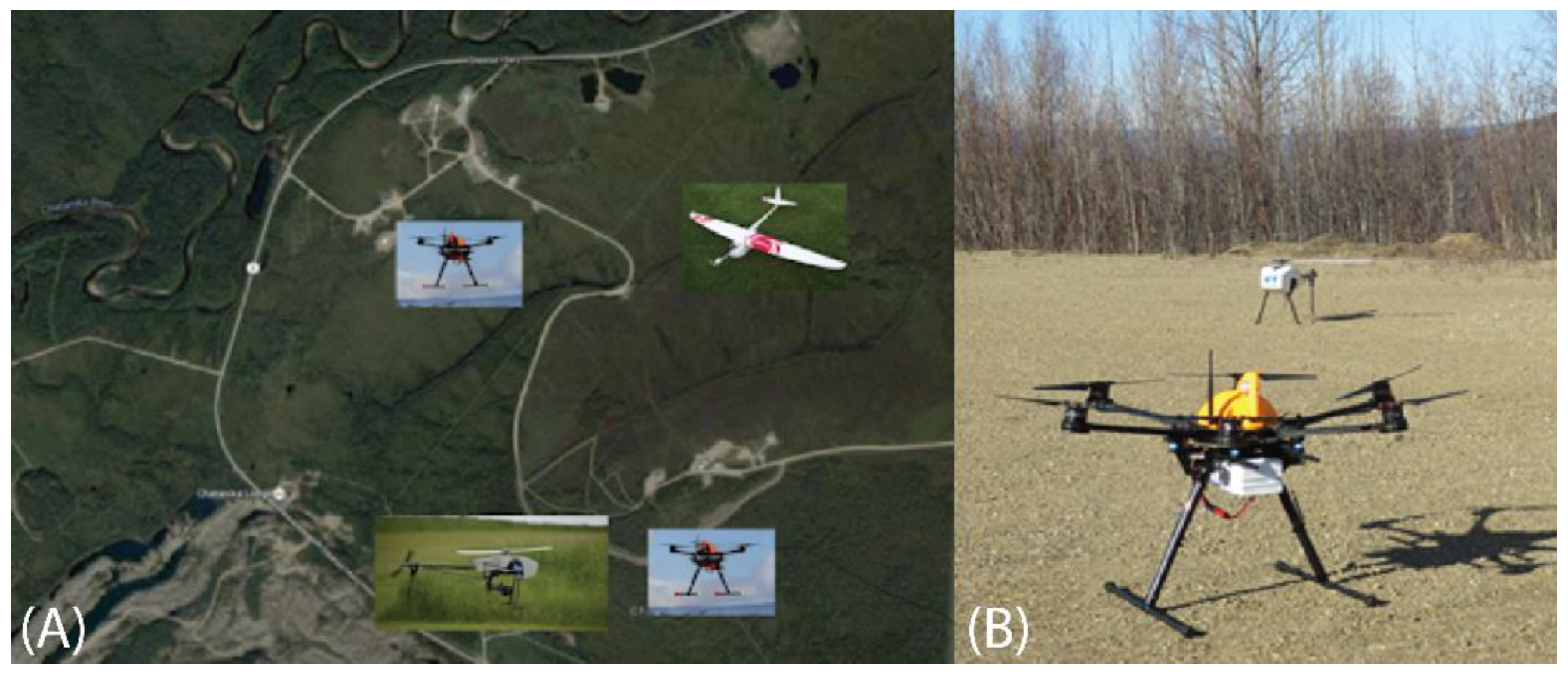
UAF was able to fly four UAS simultaneously, with two vehicles separately flown from two distinct launch locations at the Poker Flat Research Range (PFRR),
Figure 8A. One flight team operated a Ptarmigan S800 hexacopter (foreground of
Figure 8B) and an Aeromao Aeromapper fixed-wing UAS from a low-altitude location in the valley of PFRR. A second team operated the ING Responder single-rotor helicopter (background in
Figure 8B) and another Ptarmigan in adjoining airspace located up on the ridge line of PFRR overlooking the valley from approximately 200 ft altitude above the valley floor.
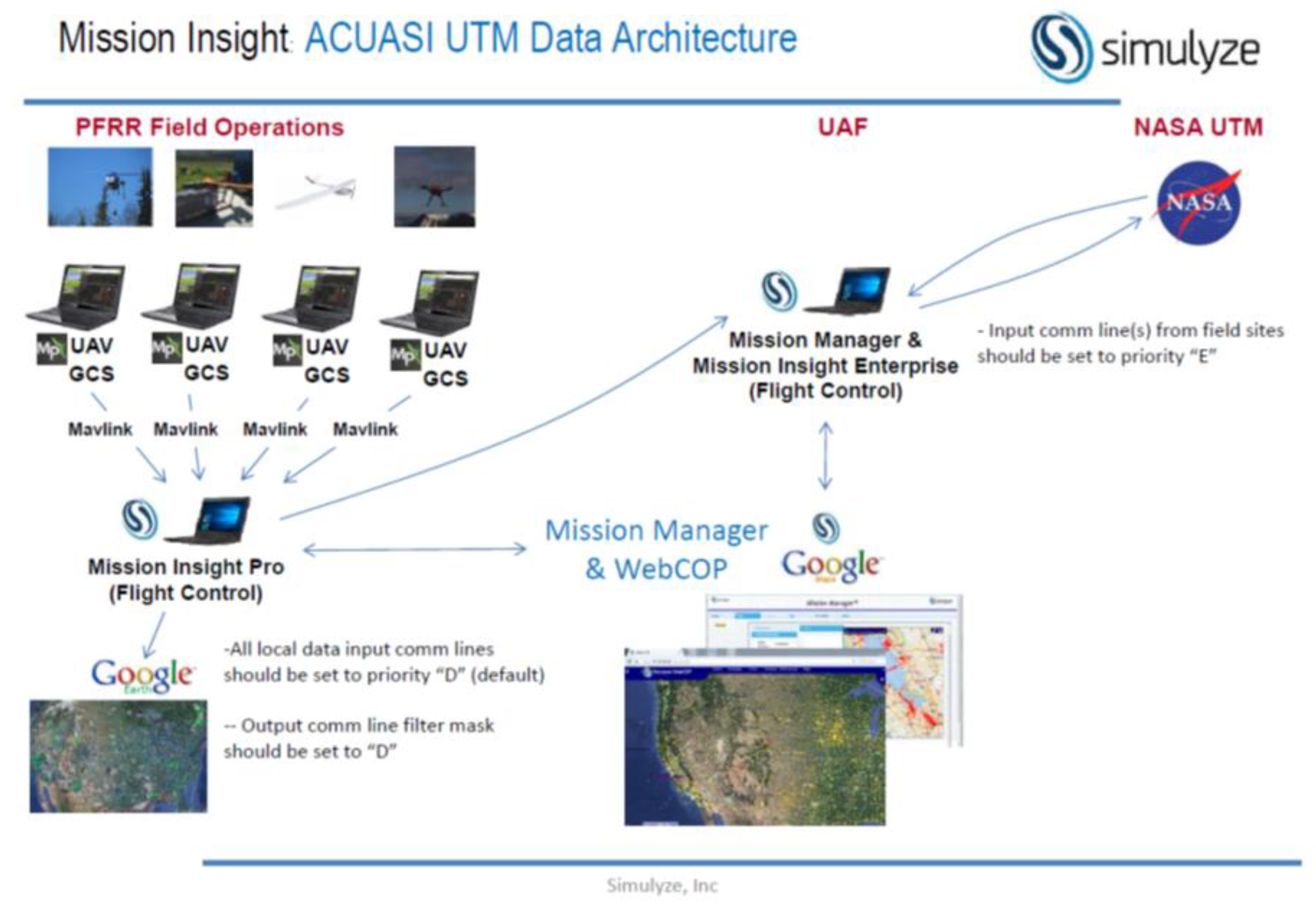
UAF’s flight operations manager coordinated and controlled flight operations via radio communications with ground pilot teams and UAF’s test manager. The test manager coordinated overall activities with NASA UTM personnel (telephone and internet), USS provider (voice and written notes), and the flight operations manager (radio). Details of the UAS/USS/UTM data communications are provided in
Figure 9.
The TCL1 demonstration was scheduled for the period of 19–21 April 2016, with the primary flight operations scheduled for 19 April/0800–1200 (AST). The flight operations period was divided up into three time windows: 0800–0900 hrs, 0900-1000 hrs, and 1000–1100 hrs. During each of these windows, each test site attempted to simultaneously operate four UAS locally. NASA stated criteria for a fully successful campaign was to have a total of 24 UAS at the six test sites performing concurrent flight operations.
UAF employed a variety of UAS types for the TCL1 campaign.
Single-rotor UAS. The ING Responder is a helicopter design based on the Gaui X7 frame and PixHawk autopilot.
Multi-rotor UAS. The ACUASI Ptarmigan is a hexacopter based on the DJI S800 frame and 3DR APM (PixHawk predecessor) autopilot. Relatively short flight times for the Ptarmigan required the UAS be recovered half-way through each flight window, then relaunched with a fresh battery.
Fixed-wing UAS. The Aeromao Aeromapper was the only fixed-wing UAS used for TCL1 and gave UAF an asset with further reach and significantly different flight performance characteristics.
UAF utilized the Simulyze UTM Client interface to pass UAS data to the NASA UTM system. Simulyze was employed by several test sites and their system was well known by NASA. UAF’s selected implementation was a single instance of the client simultaneously coordinating data for all four UAS.
Figure 9 is a schematic depicting the system architecture.
This same UTM structure was utilized by UAF during the NASA UTM TCL2 and TCL3 campaigns. A single instance of the Simulyze UTM manager was employed to input mission data (e.g., UAS vehicle identification, mission start/stop times, and status) in most cases. During some missions, multiple instances of the UTM manager were employed due to simultaneous operations involving distant locations or large numbers of UAS. As the campaign progressed, the Simulyze UTM Manager was deployed as a helpful situational awareness tool to pilots (e.g., visual indication of flight area boundaries and incursions by an aircraft or other UAS).
UTM TCL2 campaign: This phase of the program consisted of two separate flight campaigns. The first event included a selectively identified (by NASA) set of agencies participating in a centralized flight demonstration held at Reno-Stead Airport in October 2016. The major portion of the TCL2 campaign was a follow-on series of events occurring at each selected UAS test site in May/June 2017.
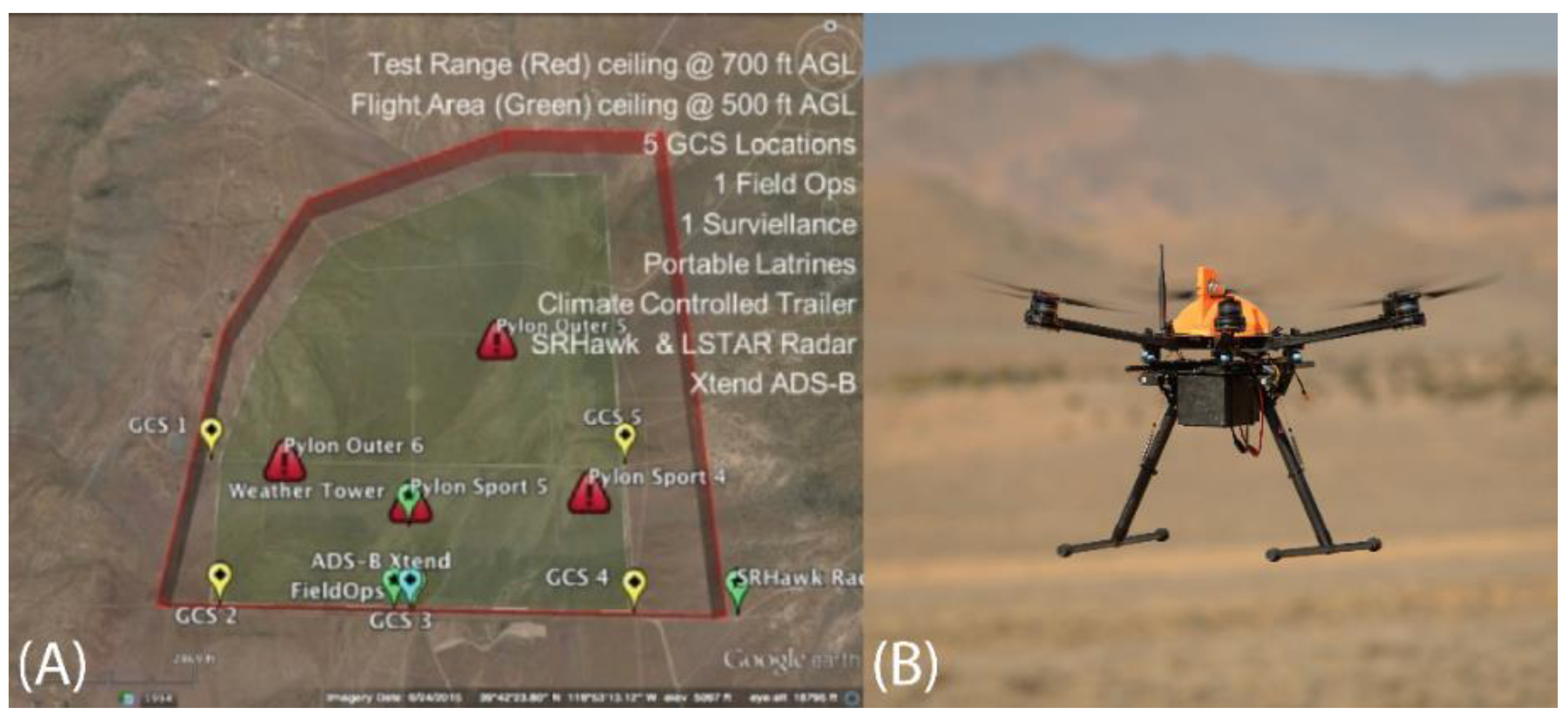
During the Reno-Stead demonstration, NASA coordinated three sets of tightly integrated flight scenarios (
Figure 10A) to be conducted between five different flight crews involving dissimilar UAS, all operating within close quarters. This provided insights into the level of coordination (both manual and autonomous) that might be required for future scenarios involving multiple different agencies and pilots conducting mixed operations utilizing a mix of UAS with various performance characteristics. UAF participated in two of the three combined scenarios using the ACUASI Ptarmigan S800 hexacopter,
Figure 10B.
The second phase of the UTM program focused on sets of identified functional objectives. The overall set of mission tasks were spread between the various partner entities with consideration to workload, technical approach, teaming arrangements, and geographical and environmental considerations. Highlights from the TCL2 SoW are listed in
Appendix A. UAF was selected to work directly on the communication, navigation, surveillance (CNS), and geofencing technologies/conformance monitoring sections of the SoW. The team also indirectly supported other NASA priorities, including USS technologies and procedures and human factors related to UTM data creation and display.
Over the period of 15 May–9 June 2017, several flights were conducted at PFRR and UAF main campus locations as part of system capability testing, shakedown tests, and demonstration. UAF’s TCL2 primary flight campaign demonstration occurred 5–9 June. UAS assets used for the missions included ACUASI’s Ptarmigan S800 hexacopter, S900 hexacopter, S1000 octocopter, ING Responder helicopter, DJI Inspire 1 quadcopter, and DJI Matrice 100 quadcopter.
The TCL2 flight campaign consisted of four scheduled flying days with a built-in makeup day. Flight profiles were scheduled for both an AM block and a PM block to support testing logistics.
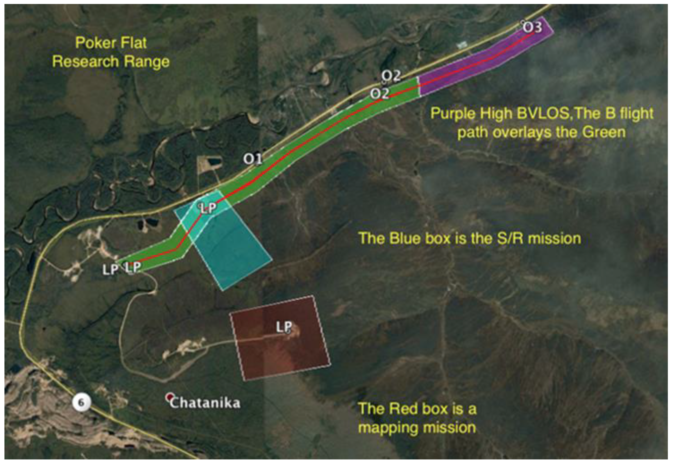
Day 1 scenario. Here, four different UAS conducted simultaneous operations, with two UAS conducting extended-visual line of sight (EVLOS) altitude-stratified flight operations and two UAS conducting local operations utilizing a combination of altitude-stratified and geographically contiguous airspace. The two UAS conducting EVLOS altitude-stratified flights along the corridor (green and purple areas) simulated a pipeline survey/inspection mission. The UAS conducting low local operations at Herder Burner (blue area) simulated either a SAR mission or vegetation mapping mission, depending upon the sensor flown. The hillside mission (brown area) simulated a dinosaur fossil mapping or glacier mapping mission (both were rehearsals for actual missions to be performed later that summer).
Flights accomplished included four simultaneous UAS: one sortie in high-altitude block (650–850’) EVLOS along the corridor (Responder); one sortie in mid-altitude block (250–550’) EVLOS along the same corridor (Matrice); one sortie in low-altitude block (0–250’) stratified local airspace (Ptarmigan); and one sortie contiguous airspace (0–500’) local operations (S1000). These flights were conducted in both the AM/PM time blocks using the airspace shown in
Figure 11.
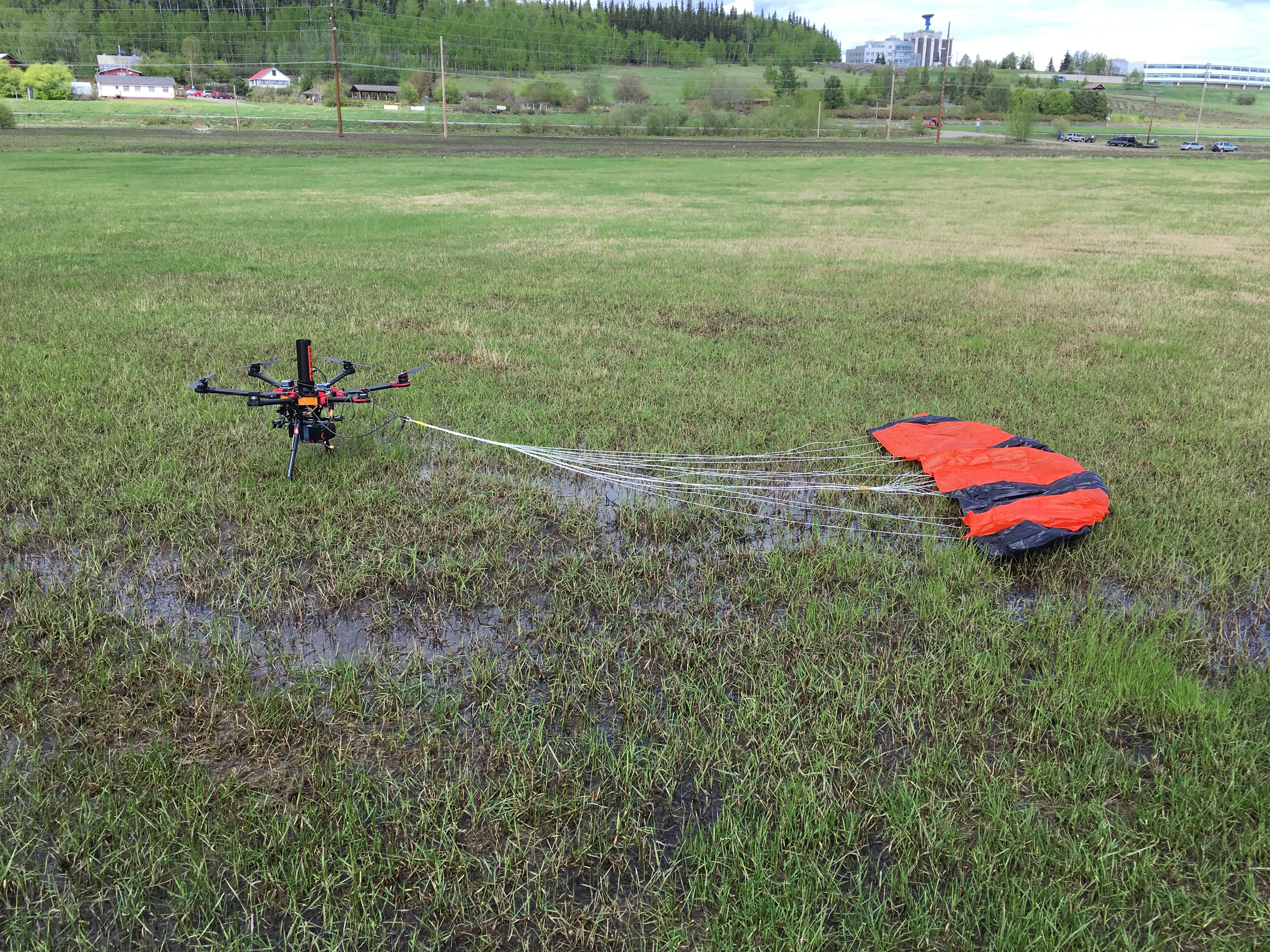
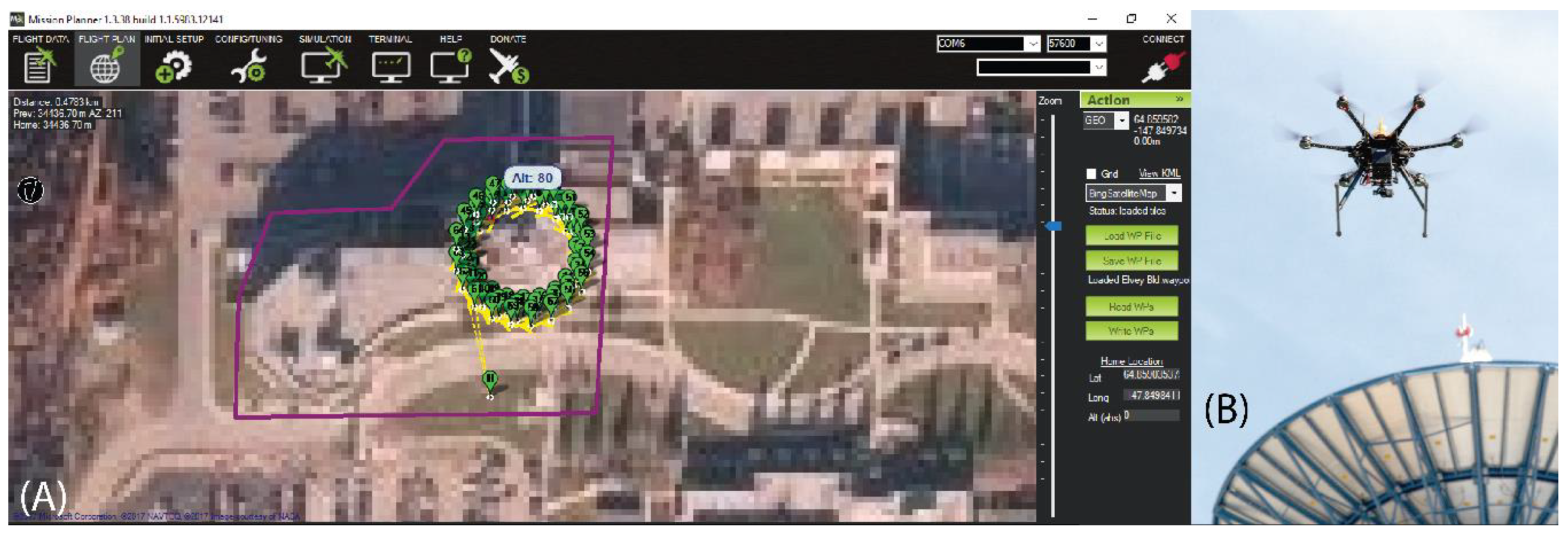
Day 2 scenario (media day). This mission set included up to five different UAS conducting simultaneous coordinated geographically separated operations, 1–2 at UAF campus and 1–2 at PFRR. The AM mission at UAF included videography of the new Elvey 9 m satellite dish by a S800 Ptarmigan UAS, as well as an airborne video of the mission taken by a DJI Inspire. The PM mission at UAF involved a lakeshore mapping of Smith Lake. The simultaneous AM mission at PFRR was the demonstration of a parachute system for multirotor UAS (S900 hexacopter). PM missions at PFRR involved an airborne SAA demonstration and Real-Time Kinematic (RTK) GPS work (S1000 octocopter).
For the UTM/USS implementation, UAF selected a semicentralized approach using one UTM Point of Contact (POC) at UAF and a second UTM POC at PFRR locations. Simultaneous operations for UAF and PFRR were achieved by coordinating launch times in advance and then communicating via text. Flight operations at PFRR were conducted in close proximity as shown in
Figure 11. The airspace utilized for UAF site missions is shown in
Figure 12A. The ACUASI Ptarmigan hexacopter performing the inspection is shown in
Figure 12B.
Flight activities during days 3 and 4 were similar to that of the day 1 scenario, but with varying altitude blocks and UAS involved. These days were also used for weather makeup, as both snow (even in June) and wind had often curtailed planned flight activities.
UTM TCL3 campaign: The third phase of the UTM program focused on more technically complex systems, which would begin to provide increasingly automated UAS/USS system capabilities to handle the additional complexities associated with higher-density UAS traffic and interactions. NASA asked the UAS test sites to consider which aspects they would focus on for their respective efforts and used a competitive bid process, enabling NASA to spread the effort between the various entities based upon the program interests and team capabilities. Highlights from the TCL3 SoW are listed in
Appendix A.
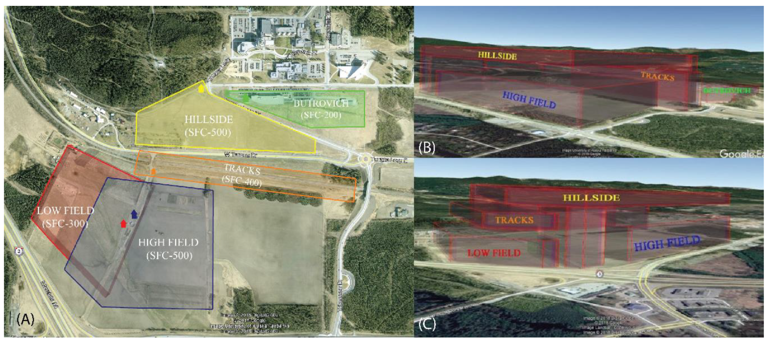
TCL3 included a series of distributed events occurring at several UAS test sites. For this campaign, UAF changed locations for flight operations from PFRR to the grounds adjacent to the UAF’s main campus. The flight airspace was divided into complex and tightly integrated geometries to increase the airspace density and UAS interaction above previous TCL2 levels. Tasks were divided into sets of major categories: (1) CNS: Communication, Navigation, and Surveillance; (2) SAA: Sense And Avoid; (3) DAT: Data and Information Exchange; and (4) CON: Concepts. UAF was selected to work on CNS1, CNS2, CON1, CON2, CON3, CON4, CON5, SAA2, and SAA4. In addition, UAF provided support to NASA for SAA3 and DAT5. An overhead perspective of the airspace blocks used for TCL3 is shown in
Figure 13A; 3-dimensional perspectives of the airspace are shown in
Figure 13B,C.
UAF’s TCL3 flight campaign was conducted during the period of 23 April–30 May 2018. In general, most flights profiles were scheduled to occur within a time block from 1000 to 1400 hrs (local). This sequencing allowed for a mission briefing each morning (0830 hrs) and setup of UAS assets, communications gear and computer networking, conduct of the mission, teardown and recovery, and then conduct of end of day mission debriefings (typically 1500 hrs). The sequencing and details of particular flight days evolved over time as a result of several factors, including coordination between UAF and NASA, experiences learned through the planning process and the developmental flight test campaign, and at times due to resource or personnel availability. Flight plans evolved over the course of the campaign to take advantage of weather conditions, experience gained during operations and shakedown tests, and NASA program desires. A discussion of flights is provided below.
CNS1, maintaining control of UA with redundant C2: The purpose of this test was to determine the effect of primary versus secondary communications link timing on UAS performance. For UAF’s CNS1 task, two different UAS were to be utilized: (1) At UAF, a F450 quadcopter UAS was tested in two different configurations: (a) two 900 MHz radios and (b) one 900 MHz radio vs. a Long-Term Evolution (LTE) 4G cellular radio. (2) In addition, UAF planned to conduct tests on its newly acquired Griffon SeaHunter UAS either at Alma, Quebec (where the flight test was already scheduled for spring 2018) or at a later time back in the United States. The SeaHunter UAS possesses three separate communications links: 900 MHz radio, 2.4 GHz radio, and iridium satellite communications. Note: This test was later cancelled due to a lack of availability of the SeaHunter during the TCL3 flight campaign.
CNS2, remaining within flight geography using GNSS navigation: The purpose of this test was to determine the effect of GPS/GNSS satellite degradation due to masking by natural terrain or man-made objects. For this task, UAF planned to utilize a S1000 octocopter as the flight vehicle and a newly acquired EchoDyne MESA®-SSR ground radar as the ‘truth source’ for the flights. The focus of the task was to determine: (1) the ability to correlate ground radar tracks with UAS position as closely as possible under ideal conditions and (2) determine the effects of degraded GPS/GNSS signals due to terrain features or man-made structures. Note: While UAF was able to complete a valuable analysis and modeling of the GNSS signals at high-latitude, with recent upgrades to both the GNSS constellations and the UAS receivers, the signal degradation never proved significant in the rural terrain or urban city environments tested.
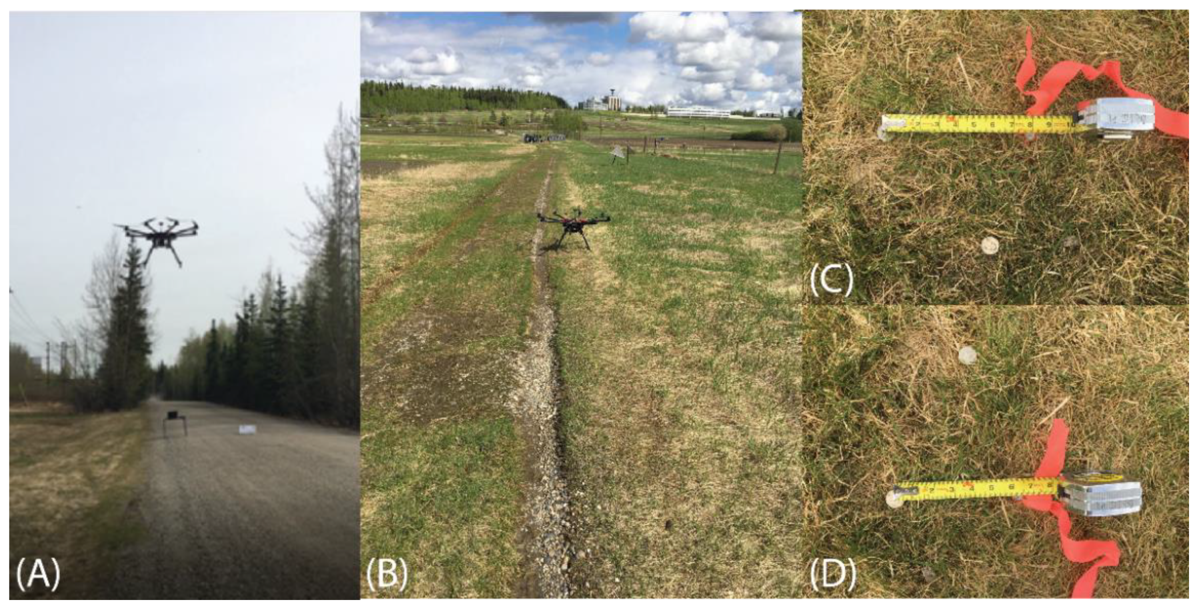
CON1, BVLOS landing: The purpose of this test was to demonstrate the ability of a UAS to autonomously conduct a BVLOS landing and subsequent take-off and return to base. This operation was conducted several times in various scenarios, incorporating different locations, distances, and numbers of remote landing/takeoff points. These were conducted, both as primary data collection missions for CON1, as well as supplementary missions added to enrich other scenarios (CON4 and CON5).
Figure 14A shows the S1000 octocopter performing a BVLOS landing ~1/2 mile from the operator.
Figure 14B shows the S1000 after landing in a 2nd location, again ~1/2 mile from the operator.
Figure 14C,D show distances measured from surveyed target locations vs actual landing points (marked by coins) at a site ~1/4 mile from the operator.
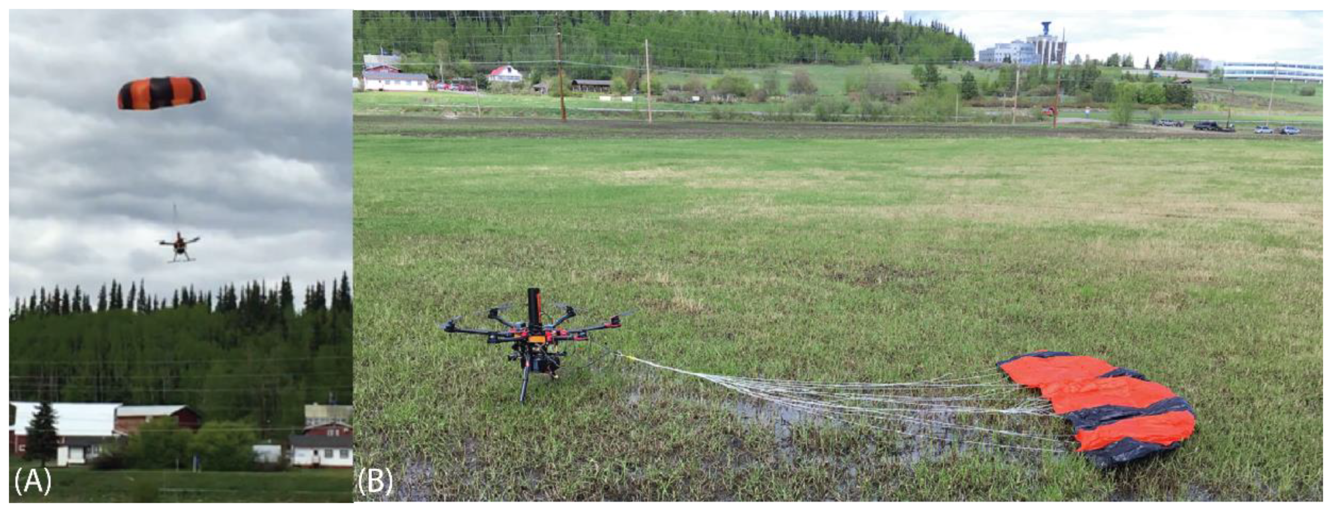
CON2, contingency initiation: The purpose of this test was to demonstrate the ability to interrupt current operations with a scripted UAS emergency necessitating activation of a prepared contingency. Actions demonstrated included: loiter well clear of the contingency operations, direct/immediate return to base (RTB), and “ditch” at a known location using parachute recovery. For efficiency of operations, flights for CON2 were designed to be conducted with interactive courseware for CON4 flight scenarios.
Figure 15A shows the S900 hexacopter under canopy during a simulated “ditch” scenario;
Figure 15B shows the S900 immediately after landing.
CON3, public portal: The purpose of this test was to develop a USS client browser and/or app-based mechanism for an anonymous member of the general public to access appropriate UTM information, and to evaluate its effectiveness through a usability study. This test was designed to utilize previously recorded flight test data (CON1/2/4/5) with both public portal and public service provider interfaces used for monitoring of UTM activity. Note: UAF was unable to complete this activity due to the schedule and repurposing of NASA UTM assets required for the development of new USS interfaces.
CON4, multiple TCL-2/3 operations for a sustained period: The purpose of this test was to demonstrate the ability of the test site operator (TSO) to fly multiple TCL-2/3 operations for a sustained period (e.g., 2 hrs). The TSO was to conduct an extended scenario with multiple interacting TCL-2/3 operations (e.g., multiple deliveries, traffic monitoring, infrastructure inspection, and real estate photography), and demonstrate that these can be conducted safely in the same airspace in a more realistic dynamic environment. For the efficiency of operations, flights for CON2 were conducted ICW with CON4 flight scenarios.
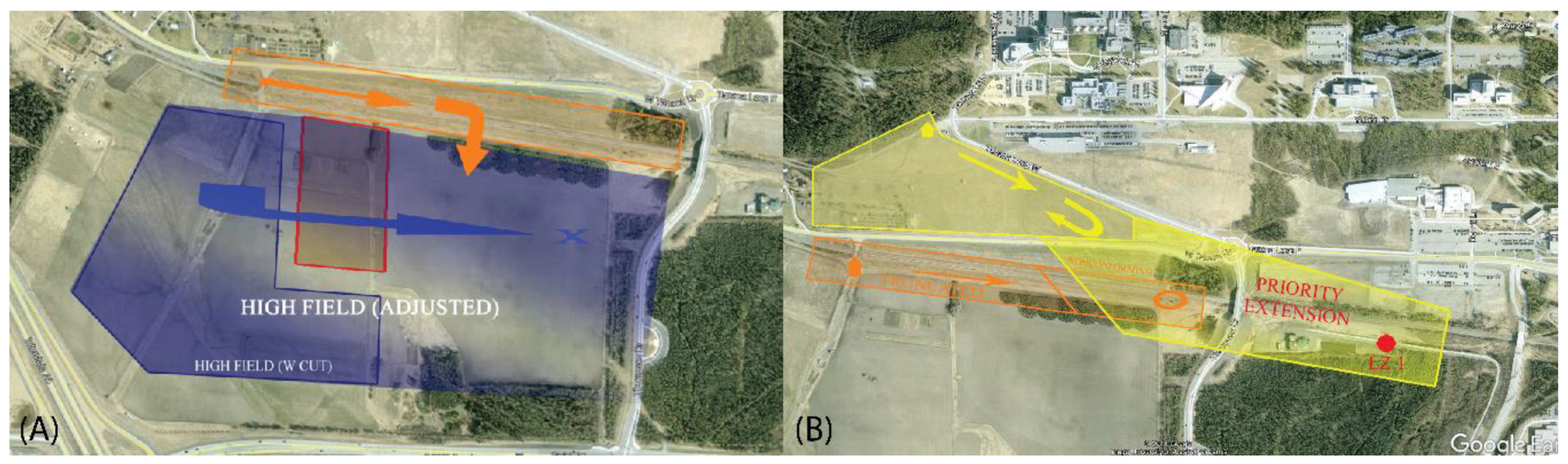
CON5, FIMS/USS interaction when a vehicle heads towards controlled or unauthorized airspace: The purpose of this test was to demonstrate an appropriate FIMS/USS interaction when a UAS heads towards controlled or unauthorized airspace. The TSO was to conduct a test where a UAS flies out of its operations volume and heads towards controlled airspace, and to demonstrate/evaluate the necessary FIMS/USS/UAS interactions supporting the scenarios. UAF was elected to demonstrate two separate categories of scenarios for CON5: (1) statically controlled airspace typically associated with traditional manned or UAS flight scenarios and (2) dynamically allocated high priority controlled airspace as a result of emergency operations (e.g., medical evacuation or delivery of critical life-saving supplies).
Figure 16A shows airspace selected for the statically controlled airspace mission;
Figure 16B shows the airspace used for the dynamically controlled scenario. For the efficiency of operations, flights for CON5 were originally designed to be conducted ICW with CON4 flight scenarios. Originally, CON4 flights were to be flown on two consecutive days, followed by the introduction of simulated contingencies comprising of CON5 scenarios. However, compression of the flight timeline due to weather delays and engineering/communications challenges caused the CON2/4/5 scenario durations and sequencing to be modified to achieve desired flight results for each without jeopardizing the overall flight schedule. As a result, initial CON5 scenarios were conducted ahead of time, separate from the larger CON4 scenarios (scheduled 21–25 May) to take advantage of good weather conditions, though with a lesser number of UAS due to limited flight crew availability.
SAA2, conflict mitigation cooperative technology for the UAS–manned interaction: The purpose of this test was to demonstrate the ability to detect airborne conflicts and resolve these utilizing an information broadcast by Automatic Dependent Surveillance Broadcast (ADS-B) technology. UAF’s approach for all SAA missions was to use a ’crawl, walk, run’ approach beginning with manual control of functions and progressing, as able, through incrementally increasingly autonomous behavior with a ‘reach goal’ of achieving fully autonomous behavior. The S1000 UAS was flown with the ADS-B to characterize its ability to accurately communicate and report its position to the Ground Control Station (GCS) via MAVLink, as displayed on Mission Planner GCS. Next, two UAS with ADS-B were flown simultaneously to determine the ability of the UTM system to accurately communicate with GCS and between the two UAS. Finally, the two UAS were flown in various cooperative profiles to determine the UTM system’s ability to report relative positional information to the GCS, and determine both the operators’ ability to manually perform separation/evasive UAS maneuvers and for the UAS to perform automatic Airborne-Based Detect And Avoid (ABDAA). To support this capability, UAF integrated an ADS-B unit with a S1000 Pixhawk to allow for ADS-B proximity data to command maneuvers. UAF’s S1000 had already incorporated RTK GPS and a laser altimeter system for increased accuracy navigation. Immediately following the formal TCL3 flight campaign, UAF successfully demonstrated the ability of the S1000 to hold short of a UAS outfitted with an ADS-B transmitter and for the S1000 to initiate lateral motion away from an aggressing UAS with ADS-B.
SAA3, conflict mitigation non-cooperative technology for the UAS-manned interaction: The purpose of this test was to demonstrate the ability to detect airborne conflicts and resolve these utilizing an information broadcast by optical obstacle avoidance technology. UAF partnered with IRIS Automation™ to demonstrate the abilities of the IRIS Hedgehog Collision Avoidance Module (HCAM) in providing SAA/ Detect And Avoid (DAA) functionality via optical sensors. As before, UAF proceeded along a ‘crawl, walk, run’ approach. The first step along this path demonstrated the functionality of the IRIS Automation HCAM system in generating data, which could be used manually by UAS flight crews to ensure separation with the encroaching vehicles. Following the success of this first step, it was hoped that the system might later be demonstrated in the autonomous mode.
SAA4, conflict mitigation non-cooperative technology for the UAS-UAS interaction: The purpose of this test was to demonstrate the ability to detect airborne conflicts and resolve them utilizing information obtained from ground radar tracks. Again, UAF’s approach utilized a ’crawl, walk, run’ approach beginning with the manual control of functions and progressing through incrementally increasingly autonomous behavior with a reach goal of fully autonomous behavior. The S1000 UAS was flown with the MESA-SRR ground radar to characterize its ability to accurately communicate and report its position to the GCS vs. MAVLink and integrate with Simulyze USS. The S1000 was then flown versus a 2nd UAS to determine the ability of the MESA-SSR to accurately detect these and pass this information to GCS. Finally, the two vehicles were flown in various cooperative profiles to determine the system’s ability to report relative positional information to the GCS, and determine the operators’ ability to manually perform separation/evasive UAS maneuvers and for the UAS to perform automatic DAA based upon commands from ground radar. Immediately following the formal TCL3 flight campaign, the UAF team demonstrated the ability to correlate the S1000 ADS-B signal with its radar track and to convert the radar track into an equivalent ADS-B format message.
3. Results
TCL1 demonstration outcomes: UAF successfully participated in the NASA UTM Build 1 UAS Demonstration (19 April 2016). UAF was able to integrate with the NASA UTM Manager and UAS client software suite to submit flight plans, track UAS operations in real-time, and close out flight plans upon termination of flight activities. UAF flew four UAS simultaneously in support of NASA goals for the demonstration. This was a significant accomplishment due to a myriad of challenging factors: (1) the short flight times (10–15 min) of most UAS assets; (2) stringent computer-communications requirements for the effort; (3) limitations imposed by early prototype NASA and third party software; (4) changing weather; and lastly (5) the need to coordinate the aforementioned factors with six test sites in four time zones across the US to get all 24 UAS in the air simultaneously.
UAF was successful in operating four UAS simultaneously and contributed to NASA meeting its stated goal of 24 UAS flying concurrently during the 1st flight window (0800–0900 hrs AST). UAF was able to get all four UAS in the air at the same time for flight window 1 (0800–0900 hrs) and flight window 3 (1000–1100 hrs). UAF was only able to launch two of the four UAS during flight window 2 (0900–1000 hrs). Difficulties during flight window 2 were attributed to challenges with multiple data links and implementation of the relatively complex system on a remote location local network infrastructure, with a temporary configuration, which had been set up specifically for this mission.
TCL2 demonstration outcomes: During the campaign, UAF successfully demonstrated the flight of 4–5 UAS simultaneously in close-proximity and various profiles, including airspace block altitude-stratified operations and EVLOS altitude-stratified operations. In addition, UAF demonstrated initial capabilities in several key technical areas: (1) successful parachute recovery of the S900 hexacopter; (2) investigation of rudimentary Detect And Avoid (DAA) between two UAS; (3) successful automated landing using laser altimeter using the S1000 octocopter; (4) initial investigation of Real-Time Kinetic (RTK) GPS; and (5) numerous improvements in the design and deployment of the computer-communications architecture supporting NASA’s internet connectivity requirements.
Several important technical capabilities underpinning the ability to conduct BVLOS flights were developed or furthered, including incorporation of more capable navigation systems, long-range communications, surveillance systems, and geofence technologies. Details of these are provided below. Unfortunately, the short program timeline and limited flight time did not allow all capabilities to be fully realized within the flight campaign itself, but postured the team for future work the UTM program and related efforts within the Initial Pilot Program (IPP).
Navigation. The laser altimeter system on the S1000 octocopter has proven highly successful, providing an unprecedented ability in accurately reporting altitude at high latitudes. The system also provided a new terrain-following capability valuable to scientific research and public service missions. In addition, the RTK GNSS system showed promise for supplying the increased accuracy needed for BVLOS missions involving landing/takeoff activities.
UAS/GCS communications: The program enabled upgrades to UAF’s purpose-built long-range UAS/GCS tracking antenna to increase its ruggedness and reliability. The antennas provide the capability of communications at significant distances (20+ km).
UTM remote communications and video: The new video monitoring system performed admirably, providing the capability to remotely monitor launch/recovery operations. Its underlying communications infrastructure also dramatically extended the team’s ability to operate using the UTM system via a portable wireless network in remote Alaska locations (which proved necessary for some flights conducted at PFRR).
Geofence and emergency response mechanisms: UAF successfully demonstrated a parachute deployment system for the S900 hexacopter. The system was tested a total of three times over the course of the flight campaign, with each resulting in a successful chute deployment and UAS recovery. This capability provides valuable options when a UAS either exceeds the boundaries of a geofence due to extreme weather (wind) conditions, experiences a navigation malfunction, or must react immediately to an ‘All Land’ command supporting an emergency scenario. The parachute system supports manual commands and can automatically deploy at dangerous UAS attitudes or for a breach of a geofence.
In the area of operational methods and procedures, UAF tackled several important areas, which proved that the feasibility of various enabling processes was necessary for a safe BVLOS flight. UAF engaged in a series of venues, which then challenged the UTM system and our ability to utilize it. The primary focus for scenarios included: (1) altitude stratified operations; (2) Extended Visible-Line-Of-Sight (EVLOS) operations; and (3) altitude stratified EVLOS operations. Additionally, UAF implemented scenarios enabling: (4) dynamic replanning; (5) response to alerts from the UTM system; and (6) implementation of contingencies (e.g., sudden need for RTB).
Multiple UAS: UAF conducted numerous mission sets involving up to five UAS flying simultaneously. This involved several scenarios, including combinations of altitude-stratified local operations and altitude-stratified EVLOS operations. The missions utilized several launch/recovery locations and demonstrated both fully centralized C2 of flight operations utilizing a single UTM operator for all UAS, as well as geographically distinct flight operations (separated by 35+ miles) with two sets of UTM operators providing simultaneous centralized C2 over local UAS operations.
UTM architecture: UAF employed a centralized approach to the UTM system using a single team member as the interface to the UTM system, with the UTM POC orchestrating the overall flight operations in close coordination with the flight director. As the missions included multiple simultaneous UAS (and crews/locations), the flight director was required to closely coordinate flight objectives and sequencing with the UTM POC in advance, so that flight boundaries and missions could be constructed, tested, deconflicted, and submitted prior to the flight.
UTM response: While UAF did not begin with the concept of having the UTM system embedded with each flight crew, we did work with the NASA human factors team to find ways to gradually introduce the UTM system displays into the crews’ equipment and incorporate this into their cross-check. We found that the crews were largely able to assimilate the UTM into their accepted procedures over time, first acknowledging audio warnings, then digesting the visual indications of flight boundaries and other UAS and aircraft in the area. Some crews became proactive in checking their flight boundaries with respect to other simultaneous flights prior to the scheduled take off.
TCL3 demonstration outcomes: UAF successfully conducted numerous flights involving 4–5 UAS simultaneously, to include tightly integrated altitude-stratified operations and dynamic airspace reallocation to support simulated emergency/high-priority operations. Technical accomplishments included: (1) numerous successful BVLOS automated landings using integrated laser altimeter/RTK systems (see video); (2) a terrain-following flight using the same as before; (3) demonstrated automated DAA using ADS-B technology; (3) UAF acquisition and successful first use of Echodyne MESA-SRR/DAA portable radar units for ground-based noncooperative DAA; and (4) successful integration of the parachute recovery system into the emergency avoidance scenario.
UAF also made significant progress in improving the use of the computer-communications equipment architecture to satisfy NASA’s requirement for constant internet connectivity of operations. Significant improvements were made in the numbers and types of portable tactical communications antennas, high-capacity cellular modems, and local wireless communications equipment, and in securing access to UAF’s computer-communications network for reliable operations.
Nearly all intended mission capabilities were demonstrated during the campaign, including incorporation of more capable navigation systems, communications, surveillance systems, and Sense And Avoid (SAA)/Detect And Avoid (DAA) technologies. Those that fell short due to time and resources continue to be addressed by UAF, especially as they are considered to be necessary capabilities for conducting BVLOS missions in the arctic. A synopsis of these is provided below.
Communications: UAF’s previous efforts focused on providing simple tactical communications between UAS and their associated Ground Control Stations (GCS). Under TCL3, the focus shifted to growing this into a fully networked system, supporting communications between the UAS, GCS, USS, as well as integrating sensors (e.g., radar) with the NASA UTM system. While elements of this system had already been demonstrated during TCL2 at PFRR, these operations had been conducted from a limited set of locations. Operations at UAF’s main campus for TCL3 required a more flexible communications system supporting numerous operating locations and associated technical assets. This drove the design to be a more complex network of field-deployable, tactical communication links enabling communications amongst participant GCS and sensor assets from remote locations, as well as providing access to internet via a combination of WiFi and/or 4G cellular networks.
Navigation: The TCL2 efforts demonstrated the basic capabilities of the laser altimeter system on UAF’s S1000 octocopters to provide the terrain-following flight and assistance in automated landing. The S1000 also featured a Real Time Kinematic (RTK) GPS system, which was shown (accomplished after the TCL2 flight campaign) to provide greatly improved capability to support BVLOS landing operations. During the TCL3 campaign, UAF demonstrated the ability of this navigation system to successfully perform BVLOS landings/takeoffs at a variety of distances and flight conditions, including multi-leg BVLOS missions involving landing/takeoff operations. This was accomplished utilizing both a smaller F550 hexacopter and the heavier-duty S1000 platforms.
SAA/DAA: UAF made significant progress in the area of SAA/DAA, improving the ability of flight crews to manually deconflict multiple vehicles using enhanced display tools and in furthering our ability to provide automatic deconfliction. Successes included: (1) improved visualization tools for flight crews on their GCS consoles, including both the standalone Simulyze USS Web Client and information injected into UAF’s Mission Planner GCS consoles already used by flight crews; (2) demonstrated ability of the Pixhawk autopilot to utilize inputs from the Automatic Dependent Surveillance Broadcast (ADS-B) on board the UAS to generate automated avoidance commands against other intruding UAS or manned aircraft (accomplished post TCL3 flight campaign); (3) demonstrated ability of the Simulyze USS to ingest and process ground-based radar inputs (EchoDyne MESA-SSR) and display this traffic on the USS Web Client and the UAS Mission Planner GCS; and (4) demonstrated ability of the IRIS Automation Hedgehog Collision Avoidance Module (HCAM) and camera system to generate and provide audio/visual traffic warnings to the UAS operator. While UAF did not complete all ‘reach-goals’ for the effort (e.g., automated separation maneuvers commanded via radar inputs), we made progress and a plan to continue.
Beyond these technical accomplishments, UAF engaged in a series of flight venues designed to further the capabilities of the UTM/USS system and our ability to utilize it. Focus for scenarios included: (1) BVLOS landing/takeoff operations (these were conducted as Enhanced VLOS operations, as we always had a safety spotter in place at the remote locations); (2) complex flight geometries in close proximity, including altitude stratified operations for CON1/2/4/5 scenarios; (3) field operations implementing flexible, deployable communications, and networking systems; (4) scenarios incorporating dynamic airspace replanning (e.g., emergency operations supporting various CON1/2/4/5 scenarios); and (5) scenarios designed to demonstrate the utility of increased visual/audio indications made available within the USS web client and UAS GCS displays.
Environmental challenges: Most mission profiles planned for the TCL3 campaign were flown either as originally scheduled or with slight modifications-necessitated by weather conditions or to provide better flight value supporting NASA objectives. Not every mission set could be accomplished with the entire UTM system in concert as planned due to a combination of factors, including UAS/system capabilities, connectivity issues of the new UAF “wheel and spoke” communications architecture, late winter breakup, and bad weather (winds, rain, and snow).
Multiple UAS: UAF performed numerous mission sets, which included flights by multiple simultaneous UAS (up to five, but generally 3–4). These missions incorporated several airspace constructs, including combinations of altitude-stratified local and EVLOS operations. The missions utilized several launch/recovery locations and demonstrated both fully centralized C2 of flight operations utilizing a single UTM operator for all UAS, as well as two sets of USS operations providing simultaneous centralized C2 over respective UAS operations (CON4).
UTM architecture: As with previous campaigns, UAF employed a centralized approach to the UTM system, generally using a single team member as interface to the UTM system. While UAF was not selected for operations involving interactions between competing USS systems, the team still successfully demonstrated this capability utilizing two separate instances of the Simulyze USS.
UTM information to flight crews: While UAF primarily utilized a centralized UTM system for all flight crews, we did increase the amount of interaction between crews and the USS Web Client. Over time the team gradually introduced the UTM system displays into the crews’ equipment and incorporated this into their mission planning and cross-check during mission execution. Not only did the flight crews demonstrate the ability to adopt this new tool, but Simulyze was able to inject much of the valuable airspace volume information and third-party UAS information (via ADS-B and the MESA-SSR radar) directly into the flight crew’s organic Mission Planner GCS, keeping the information confined to a single display and in a more familiar (and safer) format.
5. Conclusions
The UTM program has proven quite valuable in laying a foundation for integrating UAS into the NAS. Notable progress has been made on several fronts.
UTM framework and procedures: Through much hard work on the part of NASA and the FAA, the UTM architecture is becoming well-established and has been communicated widely within the UAS and manned aviation communities, both within the US and internationally. This framework has been used as an important model for the systems being investigated by the International Civil Aviation Organization and under development with other regions and countries. While a definitive set of FAA-approved procedures has yet to be released, the extensive work performed under the NASA and FAA UTM efforts has provided much of the required ground work in identifying practical, workable, and safe practices, which will form the governing policies, regulations, and practices.
UAS vehicle/sensor technologies: The UTM program has been pivotal in identifying key technologies needed to support the demanding levels of safety with respect to UAS/UTM communications, navigation, and vehicle autonomy required for high-density UAS flight within the NAS. Significant achievements have been made by the UAS test sites and their partners in several areas: (1) UAS position sensing and reporting; (2) ground-based sensors, such as radar, for tracking and GBDAA; (3) airborne sensors, such as vision-based, acoustic/ultrasonic, and lidar/radar for larger UAS; (4) automated landing/takeoff and UAS battery recharging; (5) seamless transition of UAS flight between outdoor/indoor (GNSS-denied) environments; (6) UAS vehicle health monitoring and reporting; and (7) UAS failsafe capabilities addressing lost navigation/communication (NAV/comm), lost power, and vehicle recovery after emergency landing or a crash. Much remains to be done before these systems are truly ready for the general consumer, but all issues appear to be solvable, given adequate attention and resources.
UTM communications: One overarching challenge for the UTM system remains that of providing continuous, uninterrupted communications between the UAS and the UTM FIMS via a set of USS providers. These communications may be via cellular networks, WiFi/Bluetooth, or satellite systems. Availability of cellular systems varies considerably across the nation, with ample coverage found in most urban population centers and many rural communities, yet with sparse or no coverage found in more remote locations like most of Alaska. WiFi/Bluetooth and similar networks may prove suitable when operating around major metropolitan centers, business complexes, or with groups of UAS and ground entities forming ad hoc networks. Satellite systems can provide a failsafe communications channel when no other options are available but are of much lower bandwidths.
All of these communications systems are generally bandwidth-limited with respect to sensor/payload data streams. WiFi may often prove suitable for transmitting medium or low-resolution video, but this depends upon the distance of the UAS to the GCS, power levels of transmitted signals, antenna design and placement, receiver capability, modulation scheme, and number of users sharing the link. Cellular signals often can support comparable data rates, but is also dependent on similar factors. While streaming a video may be supported close to cellular repeaters, this capability drops off dramatically further away from the GCS and may only support an occasional, lower resolution picture. Satellite communications for UAS are generally incapable of supporting anything but periodic positional reports/commands, and this may be at intervals of 2-10 min or more. Any of these systems, when present, may support basic UTM position-reporting/command functionality, but may not be sufficient for communications demanding immediate access or higher data bandwidths to support powerful sensors like the camera or radar data for SAA/DAA.
The UTM program led by NASA and the FAA has laid a solid foundation that will ultimately lead to the safe integration of UAS into the US NAS. The FAA has been in an unenviable position in attempting to strike a balance between the public outcry for opportunity and national interest in securing our place in this new market, while upholding their solemn responsibility to provide the safety demanded and deserved by our manned aviation community. While UAS integration into the NAS is not fully complete, smart progress often comes slowly.


