Numerical Modeling of Volatile Organic Compounds (VOC) Emissions during Preheating of Magnesia-Carbon Bricks in a Basic Oxygen Furnace


1
Department of Materials Science and Engineering, Process Metallurgy Research Laboratory, Computational Materials Engineering Laboratory, University of Toronto, Toronto, ON M5S 3E4, Canada
2
Dean’s Catalyst Professor, Department of Materials Science and Engineering, Faculty of Applied Science and Engineering, Cross Appointed to Mechanical and Industrial Engineering, Process Metallurgy Research Labs, 184 College Street, Toronto, ON M5S 3E4, Canada
*
Author to whom correspondence should be addressed.
Metals 2020, 10(10), 1277; https://doi.org/10.3390/met10101277
Submission received: 31 August 2020
/
Revised: 14 September 2020
/
Accepted: 16 September 2020
/
Published: 23 September 2020
Abstract
:The refractory preheating process in oxygen furnaces is a dynamic input of energy in a chemically complex system requiring special attention to chemical emissions relative to permissible release limits. This particular industrial and regulatory interest is the emission of volatile organic compounds (VOC), given their detrimental impacts on human health. In the present work, a mathematical model was developed to predict the emission rates of volatile organics during the preheating of a 260-ton basic oxygen furnace. A numerical heat transfer model was developed using finite difference techniques to obtain the thermal profile and then integrated with chemical thermodynamics using FactSage 7.0 (CRCT, Polytechnique Montreal Quebec Canada, H3C 3A7). The parameters that affected VOC emissions were preheating process times, burner gas composition, heating rate, and burner geometry. Two different preheating procedures were compared, and emission rates were predicted with extended use of a top burner providing the greatest degree of emissions control. The mathematical model was validated against plant data with respect to average emission rates of CO, CO2, SOX, and NOX.
1. Introduction
The Klockner Oxygen Blown Maxhutte (KOBM) process is a modern steelmaking technique that involves the oxidative refining of hot metal to liquid steel. KOBM furnaces use refractory lining materials such as resin- and pitch-bonded magnesia-carbon bricks with high carbon residue [1]. During the preheating of the furnace, most organic binders readily release volatile organic compounds (VOCs) with high vapour pressures, such as benzene and toluene, that then enter the atmosphere if uncontrolled. In the last decade, there has been a constant push by various environmental agencies on minimizing VOC emissions during the manufacturing and use of these carbon-containing refractories. In North America, VOC emissions are limited to regulations enforced by the US EPA [2] and Environment Canada [3]. VOCs are the primary precursors to the formation of ground-level ozone and smog [4,5], both known to have adverse effects on human health and the environment. Health effects of VOCs include an increased risk of lung cancer and heart disease [6,7], while both smog and ozone can limit agricultural productivity [8] by increasing plant susceptibility to disease, pests, and other environmental stresses. In the KOBM process, VOCs are released during the furnace preheating stage—performed after furnace relining to ensure that the refractory brick lining has dried sufficiently to reach the desired mechanical strength. Preheating also minimizes thermal shock on the hot facing of the refractory lining by minimizing the temperature difference between the heated brick and the introduced hot metal. Efforts have been undertaken by the refractory manufacturers with their upstream suppliers of carbon binders to reduce the potential of hazardous volatile emissions during preheating of KOBM furnaces [9]. These efforts typically involve experimental investigation to assess the emission behaviour of magnesia carbon bricks, with recent work by Chattopadhyay et al. [10] attempting to model emission rates during preheating of magnesia-carbon bricks via equilibrium thermodynamics. The KOBM vessel is usually preheated using a standard technique of burning solid-carbonaceous fuel (coke/wood/rags) for a duration of about 6-10 h. A bonfire is formed inside the vessel, and the heat transfer from the fire to the brick wall occurs by convection. The challenge with this technique is that there is no precise control on the flame characteristics, and also the gas composition within the KOBM. The steelmaking ladles on the other hand are preheated slowly, which lasts up to 40 h. During the first five h, the ladle is purged with hot air only. Afterwards, a natural gas burner is used as an energy source to preheat the refractory lining up to a temperature of 1000–1200 °C. So, in this study, a second procedure for preheating the KOBM was considered. It was assumed that the vessel is preheated using a natural gas burner from the top mouth of the KOBM vessel over a duration of 24 h. The two scenarios are schematically shown in Figure 1. The first procedure reflects current field practices with the second procedure designed to assess the effects of a slower preheating rate on minimizing thermal shock as well as the capability of a top-burner to combust released VOCs and sulfur compounds prior to emission from the furnace.
The most popular preheating technique for ladle preheating is the use of gas burners, where enthalpy from the combusting gasses is transformed to heat. In the steel industry, natural gas is often replaced by product gases such that blast furnace gas and coke oven gas [11]. In the preheating station, radiation heat loss is prevented by carefully using ladle lids [12]. As conventional ladle preheating has very low efficiency, several efforts have been made to improve its heating efficiency such as air preheating, and oxygen enrichment resulting in an increase in combustion temperature and decrease in gas flow rate [12,13,14]. In premixed burners, fuel and oxidizer are completely mixed before combustion takes place. As a result, it produces shorter and more intense flames. However, in industrial heating plants, a different type of burner, i.e., diffusion gas burners are mainly used where nonpremixed combustion takes place, as gas and combustion air are not mixed until they leave the burner ports. The fluid mixing process is controlled by designing the nozzle in such a way that it significantly decelerates its combustion reactions. Diffusion burners typically have longer flames with a lower maximum temperature and with uniform heat distribution [11,15,16]. Other types of burners are the staged burners. Secondary and sometimes tertiary injectors are used to supply a portion of the fuel or the oxidizer into the flame and downstream to the root of the flame. This type of burner is often used to produce longer flames, more control of heat transfer, and control of NOX formation. As a result, it produces a lower peak flame temperature with a uniformly distributed heat flux [16]. In major industrial burners, air acts as an oxidizer and pure oxygen is used to produce a high temperature and cause melting to take place [17,18]. Flameless combustion, i.e., Diluted Combustion technology is often used to increase heating system productivity without damaging the furnace or the products. Here, fuel and oxygen injections are separated, and mix together ‘locally’ with inert gasses before they react, which produces lower maximum flame temperatures with lower NOX emissions and uniform temperature distributions [18]. This particular combustion system improves ladle/basic oxygen furnace (BOF) preheating performance by reducing the average fuel consumption by 50–60% [19,20]. The use of oxyfuel instead of air-fuel makes the combustion of low calorific fuels viable which is attractive and comparable with air-fuel combustion [21,22]. Other appropriate technology is a combination of air and oxygen, referred to as oxygen-enriched air combustion [21,23]. Indirect preheating for ladle/BOF by utilizing a radiative heat source can be achieved by using porous burner technology, where combustion takes place in a porous high temperature ceramic instead of an open flame. As a result, flameless combustion takes place in the form of a glowing ceramic foam that can be used as a radiating surface for a homogeneous heat source. Due to homogeneous heat distribution within ladle/BOF, it eliminates both hot and cold spots of temperature which control problems such as airflow and associated lining damage, preheating time, and energy costs [24].
In the present work, heat transfer and field VOC emission rates from a steel plant during preheating of a KOBM furnace were combined with existing thermodynamic models into a finite difference computational model in order to obtain a more complete understanding on VOC emission rates at different stages of the preheating cycle. The heat transfer model describes the temporal variation of temperature as a function of heating flux with the thermodynamic model predicting the mass release of different VOCs as a function of temperature. Combining the two models in series, the overall model predicts the emission rates of different VOCs during the preheating process. The calculation was considered in a 260-ton KOBM vessel with a brick lining thickness of 0.72 m. The total mass of bricks used to line this vessel was ~280 tons. The total concentrations of organic compounds in the bricks, contained primarily in the carbon-based binders along with the overall brick composition considered, are shown in Table 1.
2. Modeling Approach
Preheating of the KOBM vessel is usually performed by combustion of a solid-carbon fuel such as coke or wood/rags or by combustion of natural gas if the available processing time is limited.
In the present study, two furnace preheating procedures were considered. The first procedure considered required that the KOBM solely preheated using a standard technique of burning solid-carbon fuel (coke/wood/rags) for a duration of 8 h. In the second procedure considered, it was assumed that the vessel is preheated using a natural gas burner from the top mouth of the KOBM vessel over a duration of 24 h. The two scenarios are schematically shown in Figure 1. The first procedure reflects current field practices with the second procedure designed to assess the effects of a slower preheating rate on minimizing thermal shock as well as the capability of a top-burner to combust released VOCs and sulfur compounds prior to emission from the furnace. In either preheating procedure, volatile organics compounds, as well as sulfur compounds are released as nonlinear functions of heating rate, brick temperature, and composition. Table 1 shows the boiling points of the different VOCs and sulfur as an approximate indication of their respective volatilities.
2.1. Heat Transfer Modeling
The heat transfer model was used to obtain the temperature distribution through the refractory wall and steel shell of the KOBM vessel. The major heat transfer processes involved in the preheating operation are shown in Figure 2, with radiative heat transfer occurring from the flame, and convective heat transfer occurring on both sides of the KOBM vessel walls. By consideration of the cylindrical symmetries of the KOBM vessel geometry, a one-dimensional heat transfer model is sufficient to describe the heat transfer process. This is performed by assuming the vessel is symmetrical on its central axis with the applied thermal load being unvarying with height in the vessel and conservatively taken as the maximal flux possible given the incident combustion.
Visual Basic programming was used to solve the 1D heat transfer model numerically using an explicit Forward Time-Centered Space (FTCS) finite difference approximation solved over a 1 cm-cell, 77-cell mesh comprising the entire width of the KOBM vessel shell. The numerical stability of the calculated results was minimized by noting that the Fourier number for heat transfer across the vessel shell was less than the literature-recommended [25] maximum allowable value of 0.5 as represented in Equation (1) in all mesh cells. Nonboundary interior mesh cell values were solved using an explicit first-order finite difference discretization of the one-dimensional heat equation as represented by Equation (2). The inner boundary mesh cell values were calculated by a heat balance of radiative and convective heating of the inner wall of the vessel with heat loss due to conduction to the vessel’s outer wall. In turn, the outer boundary mesh cell values were calculated by an appropriate reversal of signs to represent the heat fluxes along the vessel’s outer wall. The general form of the applied boundary equations is represented in Equation (3) where ‘q’ is a generic heat flux due to radiation, convection, or conduction. The cell volume is taken as half of the product of the mesh size ‘dx’ with an assumed cell cross-section of unity. The added factor of 0.5 is to denote that the given heat flux is applied only on one side of the mesh cell. The specific equations for each of the aforementioned heat fluxes are represented in Equations (4)–(6), respectively. The inner and outer boundary conditions showing all the superimposed heat fluxes and the initial cell temperature of 298 K are represented in Equation (7) and Equation (8). All boundary conditions are defined in Table 2.
The sign for the neighbour cell is the positive (right-side) neighbour for the inner vessel wall boundary and negative (left side) neighbour for the outer vessel wall).
The model was simplified using a reasonable convective heat transfer at the refractory hot face due to the absence of a detailed gas flow model and hot face boundary conditions of the inner converter. Gas flow conditions of the coal/wood combustion and the top gas burner are different, and a detailed 3D model is being developed to analyze the gas flow conditions.
2.2. Emission Rate Modeling
With the heat transfer model used to obtain the temperature distribution through the refractory wall and steel shell of the KOBM vessel throughout the various preheating procedures, the emission rate for VOCs and sulfur compounds can be inferred from that temperature distribution via chemical thermodynamics. Using the same 77-cell finite difference mesh as the thermal modeling, the thermal data and the concentration of VOCs and sulfur were linked through MS Excel.
For simplifying the model, it was assumed that the distribution of VOCs and sulfur within the brick is homogeneous, and VOCs do not decompose or participate in any reaction before they are fully vaporized. To compensate for this assumption, on the basis of private communications with several refractory brick suppliers, two cases were introduced to allow for variation in sulfur emission rate: 1) “Low Sulfur Emission Case” where 50% of the total sulfur was assumed to be released and 2) “High Sulfur Emission Case”, where all of the sulfur is emitted. After estimating the thermal release of the VOCs, equilibrium thermodynamic calculations were performed to account for substoichiometric and stoichiometric combustion of the organics. FactSage 7.0 [26] was used to perform the equilibrium thermodynamic calculations. For the products of combustion, the gas system equilibrium was assumed. A flowchart of the mathematical model is shown in Figure 2b, where the mass release of VOC is based on the following criteria: if, , then the VOC is released.
The vessel was divided into three areas with respect to the extent of the combustion reactions:
At the brick, where instantaneous boiling and release of VOCs and sulfur occurs;
Inside the vessel, where substoichiometric (50% stoichiometric) combustion of VOCs occurs;
At the mouth of the vessel, where stoichiometric combustion of VOCs is obtained i.e., the amount of air available is 100% of the amount of air required for stoichiometric combustion.
All VOCs were assumed to be completely reacted after being released from the bricks (i.e., no VOCs present after combustion and all VOCs are combusted into CO, CO2, H2, H2O, and other products). For the mixture of POCs (products of combustion), it was assumed that equilibrium was reached in the gas phase.
2.3. PreHeating Process Boundary Conditions and Material Parameters Utilized
The present work analyzed two preheating procedures with varying compositions of fuel burned at different potions of the KOBM vessel, as shown in Figure 1a,b, respectively. The currently-used fuel for the preheating of bricks is natural gas—schematically shown in Figure 1a—which was injected into the vessel through the bottom tuyeres (Figure 1a) at 9 Nm3/min for the first 25 min, and after that at 20 Nm3/min. During the ramming time, natural gas was charged at a flow rate of 30 Nm3/min. Wood pallets (200–400 kg), diesel (1–2 gallon) and rags (varying quantity, typically around 5 kg) were also added. The flame temperature of combustion of this fuel mixture ranges between 1773 and 1973 K based on discussions with KOBM operators. A value of 1773 K was used for the flame temperature for the currently existing scheme. Preheating was carried out over 8 h until the inner wall of the KOBM vessel reached 1273 K. The proposed preheating scheme—schematically shown in Figure 1b—will utilize only natural gas, injected into the vessel through a top burner. A value of 2250 K was assumed for the flame temperature of the proposed preheating scheme as an approximation for the combustion of a primarily methane-containing hydrocarbon mixture [27]. For either case, the material properties of the KOBM vessel were considered from material safety data sheets, supplier information, and standard heat transfer textbooks as represented in Table 2.
3. Results and Discussion
3.1. Temperature Profile of KOBM Vessel Wall as a Function of Preheating Procedure
The change of temperature from the inner to outer face of the oxygen furnace was predicted from the mathematical model (Equations (3), (7) and (8)), as shown in Figure 3a,b, for each of the analyzed preheating procedures, respectively. In either case, the initial temperature prior to preheating was uniform throughout the wall thickness at 298 K. For the present preheating procedure, the inner face wall temperature increased to around 1300 K after 8 h. However, the temperature at the outer face of the furnace only increased to around 400 K owing to the high thermal resistivity of the magnesia-carbon bricks.
For the proposed preheating operation, the inner face wall temperature increased to around 1273 K (1000 °C) after 24 h, and the outer wall temperature reached 623 K. The more elevated outer wall temperature in the case of the proposed procedure can be attributed to the longer duration allowing for the vessel shell to reach a state closer to a thermal equilibrium where the internal thermal gradients in the shell would be negligible. Correspondingly, the proposed preheating operation results in a smoother thermal profile inside the bricks with reduced thermal stresses.
3.2. Emission Rates as a Function of Preheating Completion
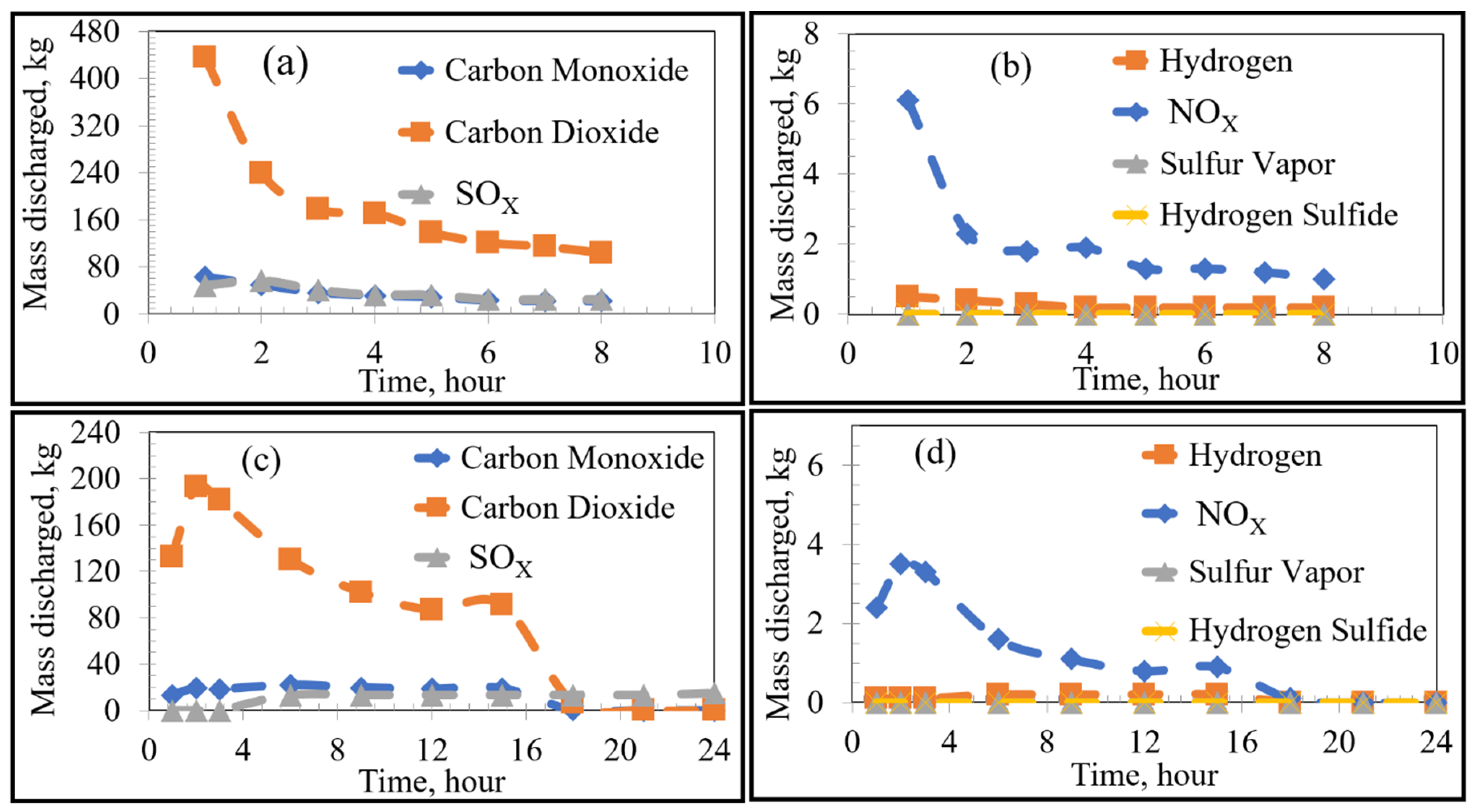
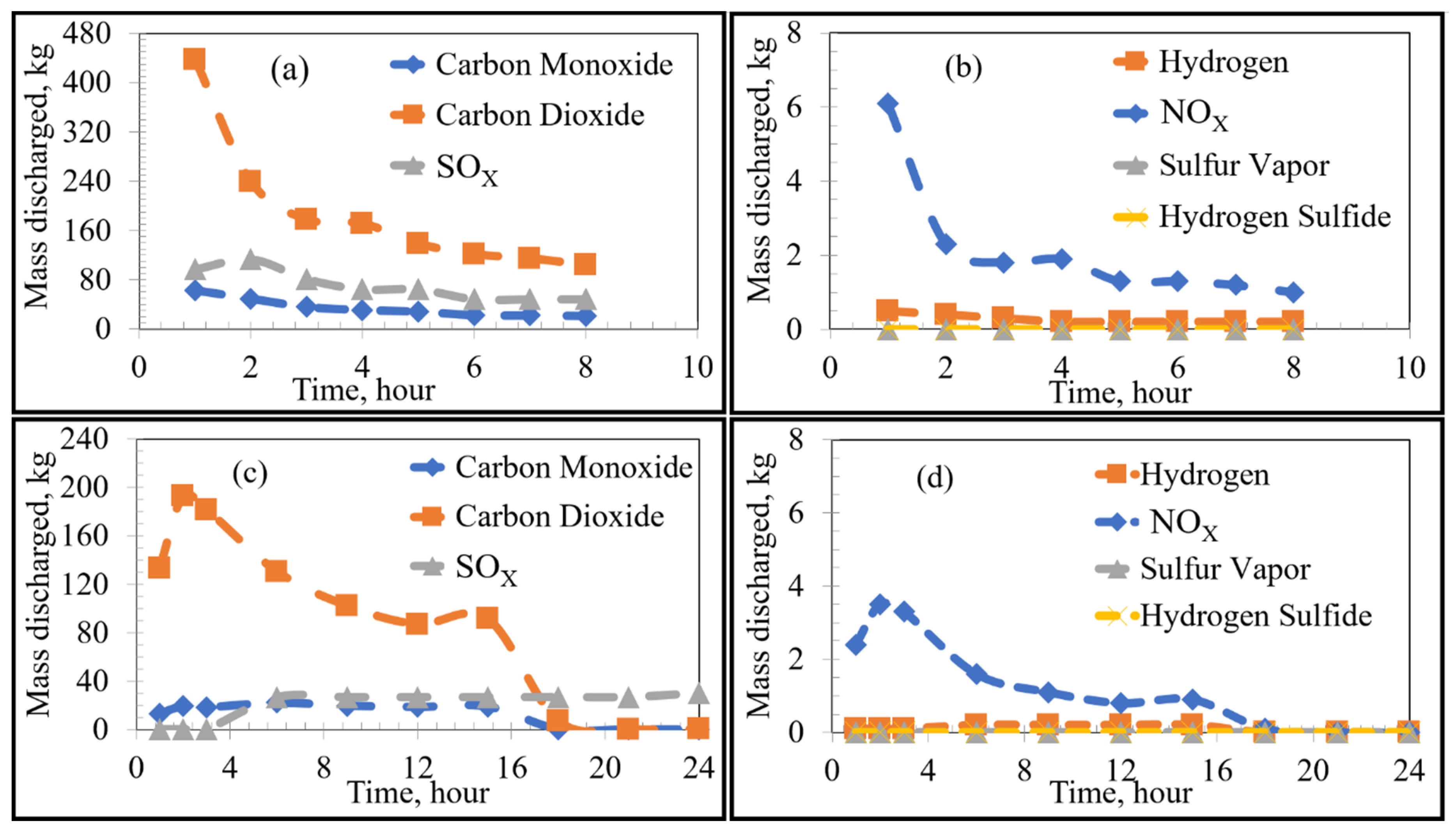
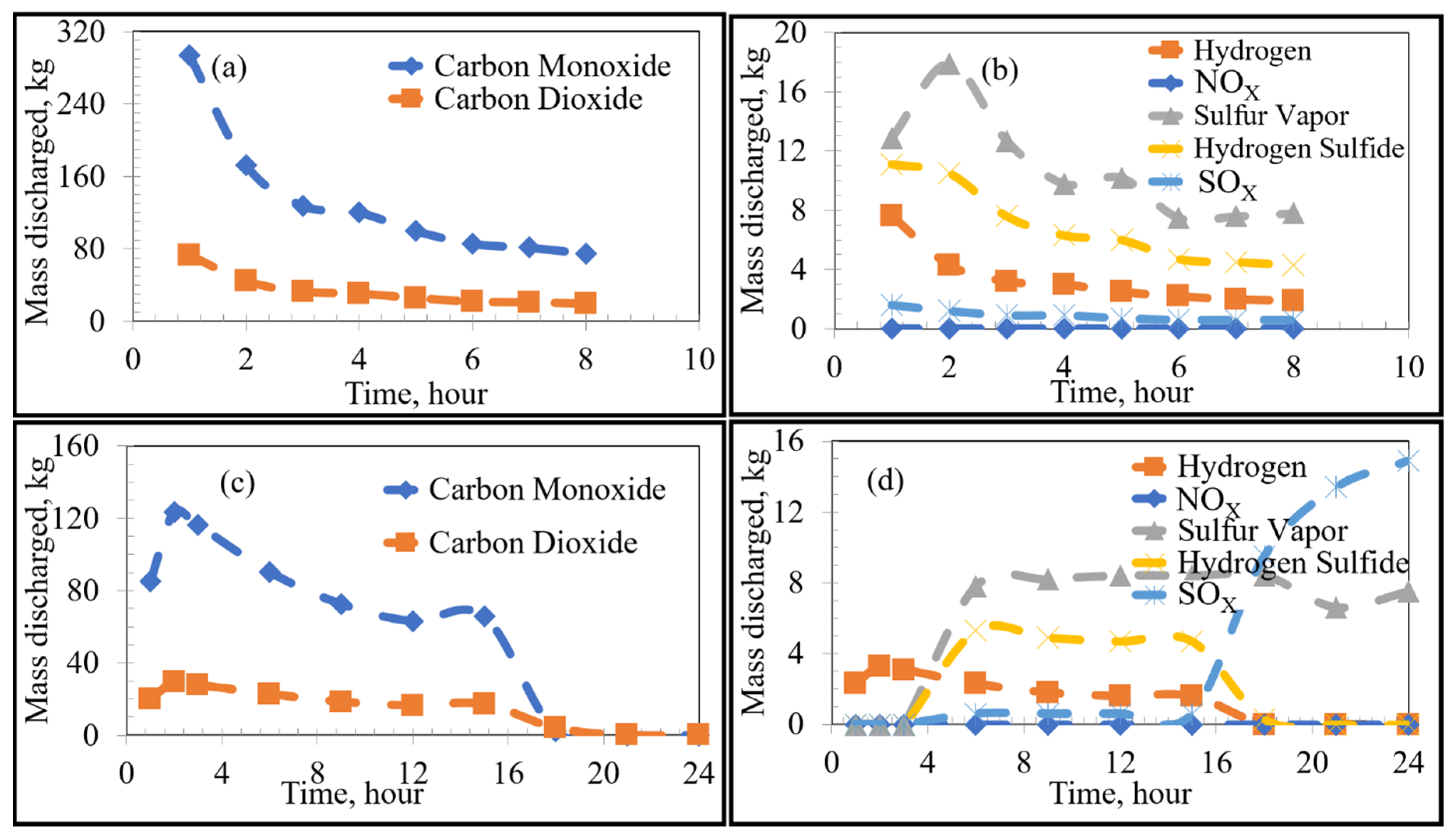
Using FactSage 7.0 to account for equilibrium thermodynamics as well as combustion reactions within the KOBM vessel, the emissions of VOCs and sulfur from the bricks as a function of time were calculated for the current and proposed preheating procedures by the numerical model and are shown in Figure 4. Emissions of VOCs and sulfur from the mouth of the furnace vessel in the case of stoichiometric combustion as a function of time were calculated for the current and proposed preheating procedures by the numerical model and are shown in Figure 5 and Figure 6, respectively. Results for substoichiometric combustion in high-sulfur cases for either of the investigated procedures are shown in Figure 7. Similarly-trending results for the low-sulfur cases are shown in the supporting information.
For the case of low-sulfur emissions, where 50% of the total sulfur was assumed to be released, the general trend of the current practice was a decrease in the rate of discharge of the VOCs and sulfur as the heating time increased. The maximum rate of emission could be observed in the first 2–3 h of heating. The rate fell to a plateau for the later part of the heating cycle. This variation in emission rates is attributed to two major factors: the boiling point of the pollutant (VOC or S) as well as the temperature distribution inside the refractory brick. As the temperature distribution along the width of the brick lining was nonuniform, there was a time lag between the onset of VOC release from the inner wall of the brick compared to the onset of VOC release from the outer edge of the brick lining. For example, in the first hour of heating, the hot face of the brick reached 900 K, while the cold face was still at 298 K. In this example, most VOCs (with boiling points ranging between 353 and 700 K) were released from the hot face with none being released from the cold face. In contrast, after 8 h of heating, the hot face was at 1300 K and the cold face at 400 K. At that point in time, all VOCs from the hot face were already released, but the release of VOCs from the cold face had just begun. A similar argument applies for any region between the hot and cold face along with the thickness of the lining. As the boiling point of most VOCs and sulfur range between 350 and 700 K, most of the emissions occur in the first 2–3 h of preheating.
The future preheating practice, conducted over 24 h, contrastingly showed varying emission rates. For example, as seen in Figure 4c, sulfur emission started after 3 h of preheating and increased steadily after that to a stable plateau. This observation is attributed to the lower heating rate of the proposed procedure in comparison to that of the current preheating procedure. As can be seen in the preheating curves, the temperature of the inner face of the vessel in the current practice reached ~1073 K after three h; whereas that of the future operation only reached ~673 K. It then follows that more heating time is required to reach temperatures sufficient for complete vaporization of the sulfur. Using the proposed preheating procedure, the emission of certain VOCs such as toluene and benzene showed a very similar trend to their current operation, but at lower quantities and mass discharge rates. It should be noted that the total emission of different VOCs and sulfur in the future operation seemed to be higher than that of the current operation (as the bricks were heated for a longer time period). However, the rate of emission (mass discharged per hour) was lower for the future case.
For the high sulfur emission cases (where 100% of the total sulfur is emitted), the behaviour of VOCs remained constant regardless of preheating procedure. The only notable difference was the higher emission of sulfur, as shown by separate curves in Figure 4a,c, labelled “Sulfur 100%”.
The VOCs and sulfur discharged from the bricks will react with oxygen in the ambient atmosphere. The thermodynamically-favoured oxidation reactions depend on the partial pressure of oxygen with reactions occurring under either stoichiometric or substoichiometric conditions. In the earlier stages of preheating, the discharge rates of the products are initially high and decrease with sufficient heating time. The proportion of carbon completely oxidized to carbon dioxide (compared to incomplete oxidization to carbon monoxide) formed varies with the inner wall temperature and partial pressure of oxygen in the furnace. The amount of formed is considerably higher under stoichiometric conditions, whereas the formation of sulfur vapour is favoured under substoichiometric conditions. This is reasonable since the formation of sulfur vapour is more probable under oxygen-deficient conditions, whereas the stability of is higher under oxygen-rich conditions. There was a significant rise in the emission from both low/high-sulfur emission cases of the proposed procedure after around 14 h as shown in Figure 7d. At the same time, there was an initial rise in other emissions from the proposed procedure followed by a decline. This observation can be correlated to the thermal profile of the bricks when compared to the boiling points of the VOCs and sulfur (Figure 3 and Table 1). In this manner, due to the relatively lower boiling points of the analyzed VOCs compared to sulfur, the inner wall regions of the refractory lining initially emitted VOCs until depleted, while sulfur remained bound in the carbon lining. The sulfur then remained bound to the carbon binding of the refractory bricks until the temperature of the lining exceeded its boiling point, effectively leading to a time lag between VOC and sulfur emissions.
The present model can be used as a dynamic tool to estimate VOC emission rates during the preheating process. It is recommended to operate above the stoichiometric conditions, as this will ensure that all VOCs are burnt before the gases exit the mouth of the KOBM vessel. This can also be performed by introducing an after-burner at the mouth of the KOBM during preheating.
3.3. Model Verification
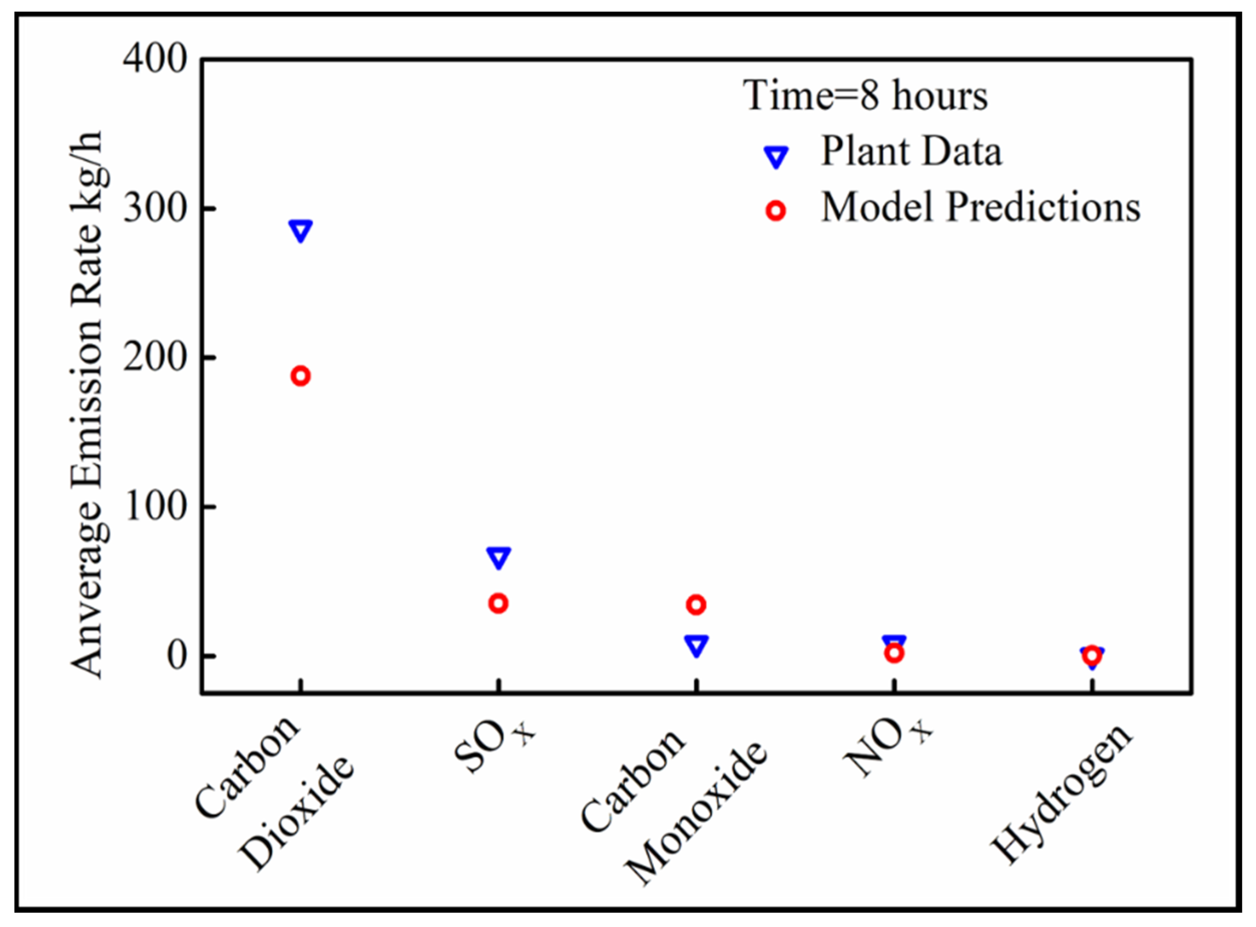
The average emission rates of CO2, CO, NOX and SOX for 8 h of preheating were measured in the plant and compared with the mathematical predictions for stoichiometric combustion of VOCs. The results are presented in Figure 8.
The mathematical model underpredicts the emission rates of CO2 and NOX. This can be attributed to the fact that a homogeneous composition of VOCs was assumed inside the brick. In reality, there can be variations in the concentration across the width of the bricks. Additionally, the model oversimplifies the heat transfer process by only assuming 1D heat transfer with the associated error. Finally, the exact chemical composition of the utilized fuel during the plant trial could differ from the assumed fuel composition in the emission rate modeling. However, the predicted trends in VOC/sulfur emission rates agree very well with the plant data and can be used for comparing different preheating scenarios.
4. Conclusions
A mathematical model was developed for use as a dynamic tool in optimizing the preheating process of a KOBM vessel for minimal emissions of VOCs and sulfur compounds. It can provide a robust estimation of the expected emission rates for different VOCs and sulfur during the preheating process. For this particular brick, most pollutants will be released during the first few hours of preheating, and thus can fail the low permit limits at the beginning of the preheating cycle. The emission release rates plateau after the first 2 h and remain fairly constant until the end of the preheating cycle. It will be easier to control emissions during preheating with a top burner over 24 h as opposed to the current practice of 8 h with burning coke, wood, and rags. The burner will ensure that proper oxygen to carbon ratios are maintained so that all the VOCs burn completely before exiting the vessel.
Author Contributions
Conceptualization, writing-review & editing, visualization, supervision, project administration, funding acquisition—K.C.; methodology, software, validation, formal analysis, investigation, resources, data curation, writing-original draft preparation—S.K.D. All authors have read and agreed to the published version of the manuscript.
Funding
This research was partially supported by the NSERC Discovery Grant and the Ministry of Research & Innovation Ontario Early Researcher Award.
Acknowledgments
The authors would like to thank the Natural Sciences and Engineering Research Council of Canada (NSERC) and the Ontario Early Researcher Award for supporting this research.
Conflicts of Interest
The authors have no conflict of interest to declare.
Nomenclature
| KOBM | Klockner Oxygen Blown Maxhutte |
| BOF | Basic Oxygen Furnace |
| VOC | Volatile Organic Compounds |
| POC | Products of Combustion |
| Fo | Fourier Number |
| dt | timestep, s |
| dx | mesh cell size, m |
| a | mesh cross-section, m2 |
| L | system length, m |
| t | system time, s |
| p | density, kg/m3 |
| Cp | isobaric specific heat capacity, J/kg·K |
| K | thermal conductivity, W/m·K |
| σ | Stefan-Boltzmann constant, W/m2·K4 |
| ε | emissivity |
| α | thermal diffusivity, m/s2 |
| Tflame, | flame temperature, K |
| Tconv | gas convection temperature, K |
| h | convective heat transfer coefficient, W/m2·K |
| q | general heat flux, W/m2 |
| qradaition | radiative heat flux, W/m2 |
| qconvection | convective heat flux, W/m2 |
| qconduction | Conductive heat flux, W/m2 |
| Tt,x | cell temperature at time t and position x, K |
References
- Buchebner, G.; Piker, S. New high preformance refractories for BOF-vessels. Veitsch-Radex Rundschau. 1996, 2, 3–14. [Google Scholar]
- Trinowski, D.M. Report-Environment improvement to UCB binders & the CORDIS processes. In Proceedings of the USEPA meeting on innovative binders for the iron and steel foundaries, Research Triangle Park, NC, USA, 26 October 2005. [Google Scholar]
- Department of the Environment, Canadian Envirmental Protection Act. 1999. Available online: http://www.gazette.gc.ca/rp-pr/p1/2017/2017-05-06/html/sup2-eng.html (accessed on 6 April 2020).
- Kesselmeier, J.; Staudt, M. Biogenic volatile organic compounds (VOC): An overview on emission, physiology and ecology. Environ. Pollut. 2000, 33, 23–88. [Google Scholar]
- Simpson, I.J.; Akagi, S.K.; Barletta, B.; Blake, N.J.; Choi, Y.; Diskin, G.S.; Fried, A.; Fuelberg, H.E.; Meinardi, S.; Rowland, F.S.; et al. Boreal forest fire emissions in fresh Canadian smoke plumes: C1-C10 volatile organic compounds (VOCs), CO2, CO, NO2, NO, HCN and CH3CN. Atmos. Chem. Phys. 2011, 11, 6445–6463. [Google Scholar] [CrossRef] [Green Version]
- Zheng, J.; Shao, M.; Che, W.; Zhang, L.; Zhong, L.; Zhang, Y.; Streets, D. Speciated VOC emission inventory and spatial patterns of ozone formation potential in the Pearl River Delta, China. Environ. Sci. Technol. 2009, 43, 8580–8586. [Google Scholar] [CrossRef] [PubMed]
- Arden Pope, C.; Burnett, R.T.; Turner, M.C.; Cohen, A.; Krewski, D.; Jerrett, M.; Gapstur, S.M.; Thun, M.J. Lung cancer and cardiovascular disease mortality associated with ambient air pollution and cigarette smoke: Shape of the exposure-response relationships. Environ. Health Perspect. 2011, 119, 1616–1621. [Google Scholar] [CrossRef] [PubMed] [Green Version]
- Chameides, W.L.; Kasibhatla, P.S.; Yienger, J.; Levy, H., II. Growth of continental-scale metro-agro-plexes, regional ozone pollution, and world food production. Science 1994, 264, 74–77. [Google Scholar] [CrossRef] [PubMed] [Green Version]
- Buchebner, G.; Sampayo, L.; Samm, V.; Blondot, P.; Peruzzi, S.; Boulanger, P. Ankersyn—A new generation of periclase-carbon refractories using a carbonaceous binder. Refract. Indistrial Ceram. 2005, 46, 291–294. [Google Scholar] [CrossRef]
- Chattopadhyay, K.; Liu, X.; Chatterjee, S. Integrated modelling of CFD and Thermodynamics for prediction of organic emissions during pre-heating of magnesia-carbon bricks. In Proceedings of the Name of the METEC & 2nd ESTAD Conference, Düsseldorf, Germany, 15–19 June 2015. [Google Scholar]
- Kramer, C.; Mühlbauer, A.; Von Starck, A. Handbook of Thermoprocessing Technologies: Fundamentals, Processes, Components, Safety; Vulkan-Verlag: Essen, Germany, 2005. [Google Scholar]
- Moch, W.; Gregor, M.A.; Adler, W.; Bender, W.; Burkat, C.; de Fries, U.; Mess, H.; Wiedemeier, F.J.; De Angelis, V.; De Paolis, G.; et al. EUR 23175-Investigations and Measures to Reduce Emissions and Energy Consumption during the Preheating of Steel Ladles; European Commission Report, Contract No RFSR-CT-2003-00008; RFCS Publications: Luxembourg, 2008; pp. 1–113. [Google Scholar]
- Volkova, O.; Janke, D. Modelling of Temperature Distribution in Refractory Ladle Lining for Steelmaking. ISIJ Int. 2003, 43, 1185–1190. [Google Scholar] [CrossRef]
- Bender, W.; Sucker, D.; Niggeschmidt, W. Neuartiges thermisches Drehgenerator-Brenner-System zur besseren Energieausnutzung in Hochtemperatur-Prozeßfeuerungen. VDI Berichte. 2001, 1629, 193–198. [Google Scholar]
- Gunther, R. Verbrennung Und Feuerungen; Springer: Berlin, Germany, 1974. [Google Scholar]
- Baukal, C.E., Jr. Industrial Burners Handbook—Industrial Combustion Series; CRC Press Inc.: Boka Raton, FL, USA, 2003. [Google Scholar]
- Kelly, J.; Dentella, F.; Recanati, A.; Visus, J.; Mielo, E. Oxygen-Enhanced ladle preheating systems: Improved tap-to-tap cycle time and operating cost reductions. Iron Steel Technol. 2011, 8, 307–311. [Google Scholar]
- Drózd-Rys, M. Impact of Steel Ladle Preheating on the Decarburization of a MgO-C Refractory Lining. Ph.D. Thesis, Montanuniversität Leoben, Leoben, Austria, March 2015. [Google Scholar]
- Manthur, P.; Riley, M.F.; Nandi, A.; Nath, R.; Ghosh, A. Improving Energy Efficiency and Reducing Emissions in the Steel Industry with Praxair’s Oxy-Fuel Technologies. Steel Tech, January 2014; No. 1, India. [Google Scholar]
- Cates, L.; Nakao, T.; Shimamoto, T. Performance and Results of Praxair’s DOC Technology for Ladle Preheating at Steel Mill in Japan. In Proceedings of the Name of the AIST Conference, Indianpolis, IN, USA, 2–5 May 2011. [Google Scholar]
- Scheele, J.; Ekman, T. Effieient Heating a With Low Calorific Gases, No. 3; Nordic Steel and Mining Review: Bergsmannen, Sweden, 2008; pp. 24–26. [Google Scholar]
- Industrial Gases Denmark. Available online: https://www.linde-gas.dk/da/processes_ren/melting_heating/ladle_heating/index.html (accessed on 28 April 2020).
- Bobek, J.; Scifres, M.; Hemandez, M.; Kelly, J. Stove Oxygen Enrichment at ArcelorMittal’s 7. Blast Furnace. In Proceedings of the Association for Iron & Steel Technology, Pittsburgh, PA, USA, 5–8 May 2008. [Google Scholar]
- Ladle Heating. Available online: https://promeos.com/solutions/ladle-heating/?lang=en (accessed on 7 May 2020).
- Pupeikis, D.; Stankevičius, V.; Burlingis, A. The effect of the fourier number on calculation of an unsteady heat transfer of building walls. J. Civ. Eng. Manag. 2010, 16, 298–305. [Google Scholar] [CrossRef]
- Bale, C.W.; Bélisle, E.; Chartrand, P.; Decterov, S.A.; Eriksson, G.; Gheribi, A.E.; Hack, K.; Jung, I.H.; Kang, Y.B.; Melançon, J.; et al. FactSage thermochemical software and databases, 2010–2016. Calphad 2016, 54, 35–53. [Google Scholar] [CrossRef] [Green Version]
- Kayadelen, H.K. Effect of natural gas components on its flame temperature, equilibrium combustion products and thermodynamic properties. J. Nat. Gas Sci. Eng. 2017, 45, 456–473. [Google Scholar] [CrossRef]
Figure 1.
Showing two preheating scenarios: (a) conventional (injection of fuels through the bottom tuyeres), (b) proposed preheating approach (injection of fuels through a top burner).
Figure 1.
Showing two preheating scenarios: (a) conventional (injection of fuels through the bottom tuyeres), (b) proposed preheating approach (injection of fuels through a top burner).

Figure 2.
Modeling schemes for: (a) heat transfer, (b) mass transfer.

Figure 3.
Heat up curve of the bricks: (a) in the current preheating procedure (8 h), (b) for the future preheating procedure (24 h).
Figure 3.
Heat up curve of the bricks: (a) in the current preheating procedure (8 h), (b) for the future preheating procedure (24 h).

Figure 4.
Emissions at the brick as a function of heating time: Low Sulfur Emission Case; (a,b) show the Current Operation, and (c,d) show the Future Operation.
Figure 4.
Emissions at the brick as a function of heating time: Low Sulfur Emission Case; (a,b) show the Current Operation, and (c,d) show the Future Operation.

Figure 5.
Emissions under stoichiometric combustion as a function of time: Low Sulfur Emission Case; (a,b) show the Current Operation and (c,d) show the Future Operation.
Figure 5.
Emissions under stoichiometric combustion as a function of time: Low Sulfur Emission Case; (a,b) show the Current Operation and (c,d) show the Future Operation.

Figure 6.
Emissions under stoichiometric combustion as a function of time: High Sulfur Emission Case; (a,b) show the Current Operation, and (c,d) show the Future Operation.
Figure 6.
Emissions under stoichiometric combustion as a function of time: High Sulfur Emission Case; (a,b) show the Current Operation, and (c,d) show the Future Operation.

Figure 7.
Emissions under substoichiometric combustion as a function of time: High Sulfur Emission Case; (a,b) show the Current Operation, and (c,d) show the Future Operation.
Figure 7.
Emissions under substoichiometric combustion as a function of time: High Sulfur Emission Case; (a,b) show the Current Operation, and (c,d) show the Future Operation.

Figure 8.
Verification of the model.


Table 1.
Composition of bricks and properties of emittable compounds in refractory lining *.
| Component | Wt. % | Component |
| Magnesium Oxide (MgO) | 83.5 | Magnesium Oxide (MgO) |
| Graphite | 16.4 | Graphite |
| Sulfur | 0.1 | Sulfur |
| Emittable Compound | kg of VOC/ton of brick used | Boiling Point (K) |
| Phenol | 1.000 | 454.7 (181.7 °C) |
| o-Cresol | 0.710 | 464.0 (191 °C) |
| p-Cresol | 0.330 | 474.8 (201.8 °C) |
| Xylenol | 0.400 | 476.0 (203 °C) |
| Toluene | 0.120 | 383.6 (110.6 °C) |
| Benzene | 0.095 | 353.1 (80.1 °C) |
| Benzaldehyde | 0.028 | 451.1 (178.1 °C) |
| Benzopyrene | 0.010 | 768.0 (495 °C) |
| Sulfur | 0.100 | 717.7 (444.7 °C) |
* All tabulated values obtained by consultation with refractory manufacturers.
Table 2.
Material properties and boundary conditions utilized in the thermal modeling study *.
| Parameters | Symbol | Bricks | Shell | Units |
| Thermal Conductivity | k | 10 | 60 | W/m2K |
| Density | ρ | 2500 | 7800 | kg/m3 |
| Heat Capacity | Cp | 960 | 502 | J/kg·K |
| Emissivity | ε | 0.1 | 0.8 | - |
| Parameters | Symbol | Existing Procedure | Proposed Procedure | Units |
| Initial/External Ambient Temperature | T0,x | 298 | K | |
| Flame Temperature | Tflame | 1500 | 2250 | K |
| Convective Temperature | Tconv | 1500 | 1700 | K |
| Internal Heat Transfer Coefficient | hout | 30 | W/m2K | |
| External Heat Transfer Coefficient | hin | 10 | W/m2K | |
* Material properties determined by consultation with refractory manufacturers and material safety data sheets.
© 2020 by the authors. Licensee MDPI, Basel, Switzerland. This article is an open access article distributed under the terms and conditions of the Creative Commons Attribution (CC BY) license (http://creativecommons.org/licenses/by/4.0/).
Share and Cite
MDPI and ACS Style
Dinda, S.K.; Chattopadhyay, K. Numerical Modeling of Volatile Organic Compounds (VOC) Emissions during Preheating of Magnesia-Carbon Bricks in a Basic Oxygen Furnace. Metals 2020, 10, 1277. https://doi.org/10.3390/met10101277
AMA Style
Dinda SK, Chattopadhyay K. Numerical Modeling of Volatile Organic Compounds (VOC) Emissions during Preheating of Magnesia-Carbon Bricks in a Basic Oxygen Furnace. Metals. 2020; 10(10):1277. https://doi.org/10.3390/met10101277
Chicago/Turabian StyleDinda, Soumitra Kumar, and Kinnor Chattopadhyay. 2020. "Numerical Modeling of Volatile Organic Compounds (VOC) Emissions during Preheating of Magnesia-Carbon Bricks in a Basic Oxygen Furnace" Metals 10, no. 10: 1277. https://doi.org/10.3390/met10101277
Note that from the first issue of 2016, this journal uses article numbers instead of page numbers. See further details here.