
Abstract
This paper develops a twist beam for multi-directional energy harvesting using piezoelectric transduction. The working principle of the multi-directional ability is explained by the theory of a pre-twisted beam. A simulation study is performed for concept verification and revealing the potential advantages of the proposed twist-beam vibration energy harvester (VEH). A physical prototype is fabricated and an experimental study is conducted to evaluate the actual performance of the proposed twist-beam VEH for validation. The results show that for the excitation comes from any direction in the plane in parallel with the beam cross-section, the proposed twist-beam VEH can produce a substantial amount of power. The optimal resistance is independent of the excitation direction. Moreover, it is found that the relationships between the output voltage amplitude and the excitation direction are different for the cases around the first and second resonances of the twist-beam VEH. The underlying physics behind this phenomenon is that the dominant motion of the two resonant modes are contrarily different. In addition, the experimental study shows that the first two natural frequencies of the prototyped twist-beam VEH are 22.37 and 41.47 Hz, respectively, which are much closer to each other as compared with those of a conventional plain beam. This feature benefits multi-modal energy harvesting within a targeted frequency range. The prospects regarding further optimization of the proposed twist-beam VEH are discussed.
Export citation and abstract BibTeX RIS
1. Introduction
Harvesting energy from ubiquitous environmental vibrations is widely deemed as a promising sustainable power solution for perpetual wireless sensors and thus has been extensively developed in the past few decades [1–5]. Since the ubiquitous vibration energy often spreads over a wide frequency range and presents with a time-varying frequency, broadening the operation bandwidth and improving the transduction efficiency are the two concerns that have attracted wide attention by the existing literature. Various strategies such as introducing nonlinearities [6, 7], designing multi-modal/self-adaptive structures [8, 9] and using advanced interface circuits [10, 11] have been proposed to address the two concerns.
Another problem which is often ignored but critical in the practical application of vibration energy harvesters (VEHs) is that the mechanical vibrations in industrial facilities, civil infrastructures, and human motions usually feature with multi-directionality. Most energy harvesters are conventionally designed based on plain beam structures. If the excitation direction deviates from the beam bending direction, the beam cannot be properly excited and the power outputs from these conventional plain beam VEHs will decrease dramatically. To this end, Chen et al [12] designed a dandelion-like VEH that consisted of multiple cantilever piezoelectric beams being installed in different orientations for harvesting vibration energy from different directions. Zhou et al [13] investigated a multi-directional zigzag VEH that is also constituted of multiple piezoelectric cantilever beams being connected and coupled through joint blocks in a snake-like form. Deng et al [14] prototyped a multi-directional VEH by coupling three cantilever piezoelectric beams in a T-shape. Also adopting multiple piezoelectric beams, Wang et al [15] presented a cross-coupled dual-beam structure for harvesting energy from vibrations induced by wind vortices from different directions. The aforementioned designs are all achieved by using multiple piezoelectric beams and more related research can be found in [16, 17], one drawback is that multiple outputs of the piezoelectric transducers pose the difficulty in power management.
Based on the internal resonance of nonlinear systems, Xu et al [18] and Wu et al [19] proposed multi-directional VEHs by attaching a pendulum to a typical cantilever VEH and a binder clip based VEH, respectively. Due to the internal resonance, the horizontal direction excitation can also induce the vertical direction vibration of the piezoelectric beam to generate power output. However, the internal resonance based multi-directional energy harvesters are highly sensitive to the system parameters. A mistuning of the system parameters may easily result in the disappearance of the internal resonance phenomenon and the loss of the multi-directional ability. Besides the approaches of using multiple cantilever beams and internal resonance, Gu et al [20] designed an innovative structure with a magnetic ball moving on a two-dimensional surface for in-plane multi-directional vibration energy harvesting. Yang et al [21] developed a system that consisted of a doubly-clamped elastic rod and a compressive-mode piezoelectric transducer for harvesting vibrations from multiple directions. Kim et al [22] presented a multi-directional energy harvester using a bump structure that can vibrate both translationally and torsionally. Other designs for multi-directional energy harvesting can be achieved through the introduction of non-unidirectional magnetic interactions [23, 24]. Several more related research of multi-directional energy harvesting can be found in a review article [25].
According to the literature review, the research of multi-directional energy harvesters is still in the infancy stage and there are still limited means for realizing multi-directional energy harvesting. In this letter, we propose a novel multi-directional VEH using a different mechanism. The proposed multi-directional VEH employs a single beam and a single piezoelectric transducer, thus it has a more compact design and can ease the subsequent power management. In addition, the proposed multi-directional VEH does not rely on any nonlinear phenomena, therefore can exhibit a relatively robust multi-directional energy harvesting ability.
2. System description and mechanism explanation
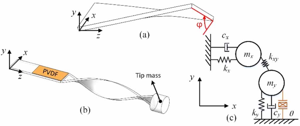
The governing equation of a pre-twisted beam segment (figure 1(a)) can be written as [26]:
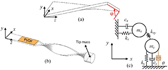
Figure 1. (a) A pre-twisted beam segment, (b) the proposed twist-beam VEH, (c) a lumped 2-DOF equivalent.
Download figure:
Standard image High-resolution imagewhere E, ρ and A are the Young's Modulus, mass density and the cross-section area of the beam. Iy
and Ix
are the moments of inertia of the cross-section about the y-axis and x-axis, respectively. Ixy
is the product of inertia which is a function of the twist angle  . v and w are the flexural displacements of the beam in the x and y directions, respectively. Fx
and Fy
are the distributed load applied on the beam in the x and y directions, respectively. It is worth noting that for a plain beam, Ixy
constantly equals to zero, leading to the degeneration of equation(1) into two decoupled equations. Hence, the flexural displacements of a plain beam in the two directions can be addressed independently. However, when the beam is pre-twisted, flexural displacements take place concurrently in the two perpendicular planes because of the non-zero term Ixy
. For simplicity, we consider that the twist beam is obtained by pre-twisting a uniform beam and the cross-section remains symmetric about the two principal axes of inertia.
. v and w are the flexural displacements of the beam in the x and y directions, respectively. Fx
and Fy
are the distributed load applied on the beam in the x and y directions, respectively. It is worth noting that for a plain beam, Ixy
constantly equals to zero, leading to the degeneration of equation(1) into two decoupled equations. Hence, the flexural displacements of a plain beam in the two directions can be addressed independently. However, when the beam is pre-twisted, flexural displacements take place concurrently in the two perpendicular planes because of the non-zero term Ixy
. For simplicity, we consider that the twist beam is obtained by pre-twisting a uniform beam and the cross-section remains symmetric about the two principal axes of inertia.
Based on the aforementioned mechanism of a pre-twisted beam, we are inspired to design a multi-directional energy harvester as shown in figure 1(b). The proposed multi-directional VEH mainly consists of two segments: a plain beam segment and a pre-twisted beam segment. A piezoelectric transducer is installed onto the plain beam segment. A cylinder mass is attached to the free end of the pre-twisted segment. Due to the employment of the pre-twisted segment, it can be expected that regardless of the direction of base excitation in the x-y plane, the y-directional flexural displacement of the beam can always be stimulated to guarantee the operation of the piezoelectric transducer for power generation. The working principle of the proposed twist-beam VEH is illustrated in figure 1(c) through a simple lumped two-degree-of-freedom (2-DOF) model. Similar to the one-degree-of-freedom representation of a typical cantilever beam, the unequal flexural rigidities of the beam in the two directions can be equivalently represented by two stiffnesses (i.e. kx
and ky
). The flexural vibrations in the two directions are described by two separated DOFs and can be regarded independent for a plain beam. However, the non-zero Ixy
of the pre-twisted beam gives rise to a new stiffness term kxy
that couples the dynamic motions in the two perpendicular directions. The stiffness kxy
can be tuned by changing the twist angle  . Therefore, even only under the x-directional excitation, the dynamic motion of the y-directional DOF can be stimulated and the piezoelectric transducer coupled with the y-directional DOF can realize energy transduction. It is worth mentioning that the simple 2-DOF model is just used to help the understanding of the working principle of the twist-beam VEH. A more rigorous derivation of the equivalent lumped parameters is worth further investigation but it is not the focus of this letter.
3. Simulation for proof-of-concept
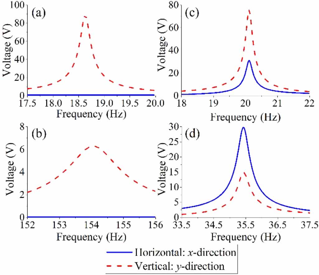
For concept verification, a finite element model of the proposed twist-beam VEH is built. Except that the host beam is assumed to be made of steel and the piezoelectric transducer material is PZT-5H, the system parameters of the simulation model are the same as the physical prototype that will be introduced in the subsequent section and the twist angle is 180°. A conventional cantilever VEH with the same effective length is also built for comparison. Figures 2(a) and (b) show the open-circuit voltage responses of the conventional VEH around the fundamental and second resonances, respectively. Figures 2(c) and (d) show the corresponding results of the twist-beam VEH. The blue solid line denotes the result when the excitation is applied horizontally in the x-direction and the red dashed line represents the result when the exaction is applied vertically in the y-direction. The flexural bending direction of the conventional plain beam VEH is aligned with the vertical y-direction. It can be observed that when the excitation is in the horizontal direction, the voltage response from the conventional VEH is zero (i.e. figures 2(a) and (b)). While, the proposed twist-beam VEH can always produce a substantial amount of voltage output in response to excitations in both horizontal and vertical directions (i.e. figures 2(c) and (d)). Moreover, it is noted that around the fundamental resonance, the twist-beam VEH produces a higher voltage output when the excitation direction is vertical. However, around the second resonance, the twist-beam VEH produces a higher voltage output when the excitation direction is horizontal.
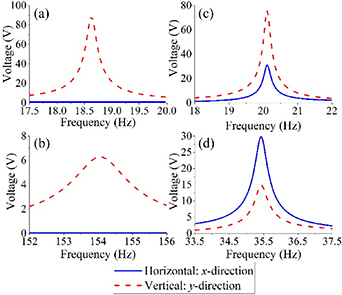
Figure 2. Simulated open-circuit voltage frequency responses of a conventional plain beam VEH around (a) fundamental resonance and (b) second resonance; simulated open-circuit voltage frequency responses of a twist-beam VEH around (c) fundamental resonance and (d) second resonance. The blue solid line and the red dashed line, respectively, denote the results when the excitation is applied horizontally in the x-direction and vertically in the y-direction.
Download figure:
Standard image High-resolution imageIn addition to the voltage output amplitude, by comparing figures 2(b) and (d), one can note that the second resonant frequency of the twist beam VEH is much lower than the conventional plain beam VEH. To further investigate the effect of pre-twisting process on the natural frequencies of the beam, figure 3 plots the first two natural frequencies of the twist-beam VEH versus the twist angle. It is worth mentioning that when the twist angle equals to zero, the twist-beam VEH degenerates to a conventional plain beam VEH. From figure 3, it is learned that with the increase of the twist angle, the first natural frequency slightly increases and the second natural frequency dramatically decreases. Since a resonant-type energy harvester can only operate near the resonance, as the first two natural frequencies getting closer to each other, the effective bandwidth within the assumed targeted frequency range becomes larger. Therefore, the proposed twist-beam VEH is expected to be beneficial for not only multi-directional but also multi-modal vibration energy harvesting.
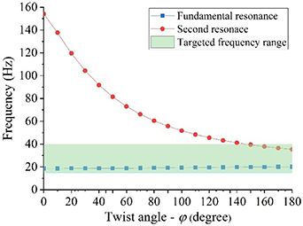
Figure 3. First two natural frequencies of a twist-beam VEH versus the twist angle ϕ.
Download figure:
Standard image High-resolution image4. Physical prototype and experimental setup
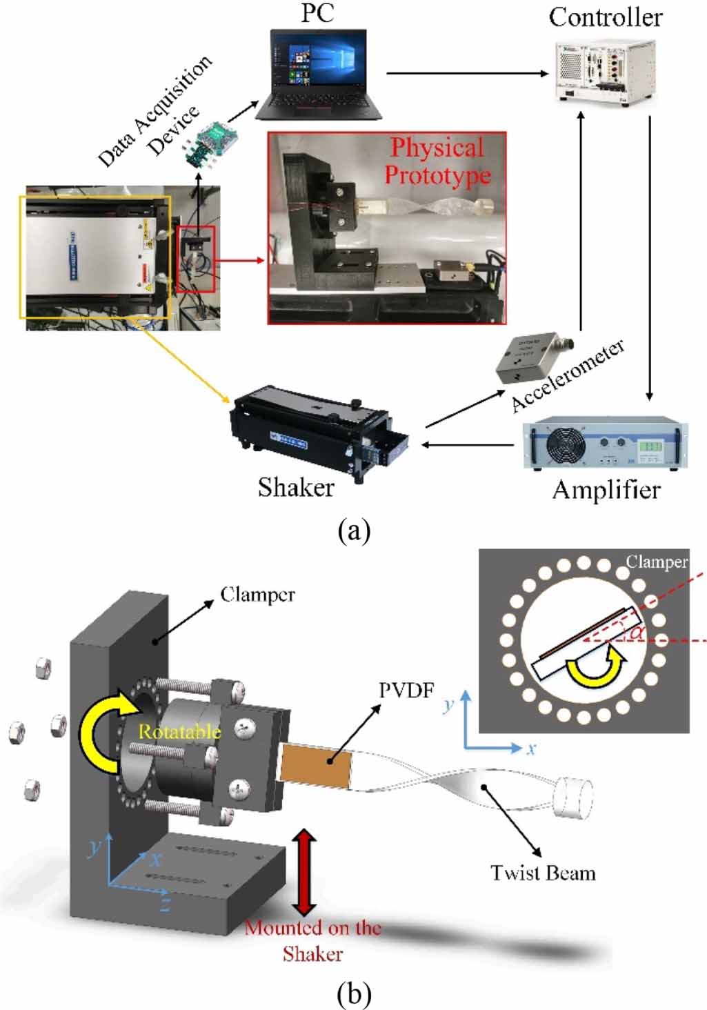
Due to the complexity of the geometry, the proposed twist-beam VEH is prototyped using the PMMA material by 3D printing technique. Figure 4(a) shows the fabricated physical prototype and the experimental setup. The mass density of the 3D printing material is measured as 1161 kg m−3 and the Young's modulus is provided by the supplier as 75–110 MPa. The lengths of the plain and pre-twisted segments are 46 and 80 mm, respectively. Twenty millimetre of the plain segment is reserved to fit the installation onto the clamper and only the other 26 mm of the plain segment contributes to the effective length of the twist-beam VEH. The beam cross-sections of both the plain and pre-twisted segments are the same: the width and the thickness are 14 and 1.5 mm, respectively. The pre-twisted shape is created by using a helix command in CAD software. Over the span of 80 mm, the helix is twisted for 0.6 turn. The diameter and the length of the tip mass cylinder are 14.32 and 10 mm, respectively. The length, width, and thickness of the piezoelectric transducer (PVDF, LDT0-028 K) are, respectively, 23.5, 10.2, and 0.2 mm. The capacitance of the piezoelectric transducer is 480 pF.
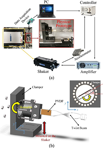
Figure 4. (a) Fabricated prototype and experimental setup, (b) installation of twist-beam VEH to a rotatable clamper.
Download figure:
Standard image High-resolution imageTo evaluate the multi-directional ability, a rotatable clamper is designed to control the orientation of the twist-beam VEH, as illustrated in figure 4(b). α is defined as the orientation angle of the twist-beam VEH. Using this clamper, a series of discrete orientation angles can be achieved with an increment of 15°. Because of rotational symmetry, we only need to vary α from 0° to 90° in the experiment. α = 0° and 90° indicate that the beam thickness direction is in align with the y-direction and x-direction, respectively.
The whole experimental setup is deployed as follows. The clamper is installed on the shaker (APS-113) that is used to generate the desired excitation. The excitation profile can be defined and edited through the PC software which communicates with the controller (PXL-1036) to produce the command signal. The amplifier (APS-145) magnifies the command signal before being fed to the shaker. A feedback accelerometer is attached to the shaker and connected to the controller to form a close-loop control. The electrodes of piezoelectric transducer are bridged to a data acquisition system (Analog Discovery 2) for recording the voltage response.
5. Experimental results
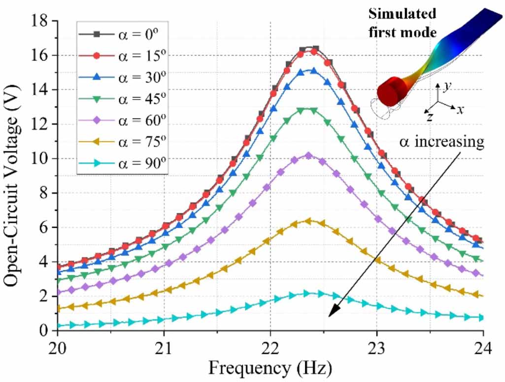
Figure 5 shows the open-circuit voltage frequency response of the twist-beam VEH. The excitation frequency is swept from 20 to 24 Hz at the rate of 2 Hz min−1. The excitation acceleration is kept at 0.5 × g (g = 9.8 m s−2 is the gravitational constant) during sweep. It is noted that the fundamental resonant frequency of the twist-beam VEH is around 22.37 Hz. At the fundamental resonance, when α = 0°, the maximum open-circuit voltage amplitude is about 16.48 V. With the increase of α, the open-circuit voltage amplitude decreases. The physical explanation behind this is as follows. Though the fundamental resonant vibration of the coupled-segments formed beam include components in both directions, the main component is in the thickness direction of the plain segment. When α = 0°, the thickness direction is exactly aligned with the excitation direction, the open-circuit voltage amplitude is thus significantly large. On the contrary, when α = 90°, the thickness direction becomes perpendicular to the excitation direction and the open-circuit voltage amplitude is dramatically decreased to about 2.18 V. Though the output voltage amplitude is small at α = 90°, this multi-directional energy harvesting ability is a plus compared with the plain beam VEH. Due to the rotational symmetry, we can conclude that in the x-y plane, regardless of the excitation direction, voltage can always be generated by the twist-beam VEH.
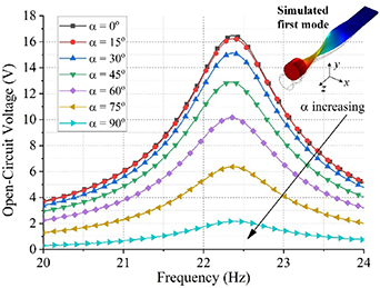
Figure 5. Experimentally obtained open-circuit voltage frequency response of the twist-beam VEH around the fundamental resonance for different orientation angle α under the base excitation of 0.5 × g.
Download figure:
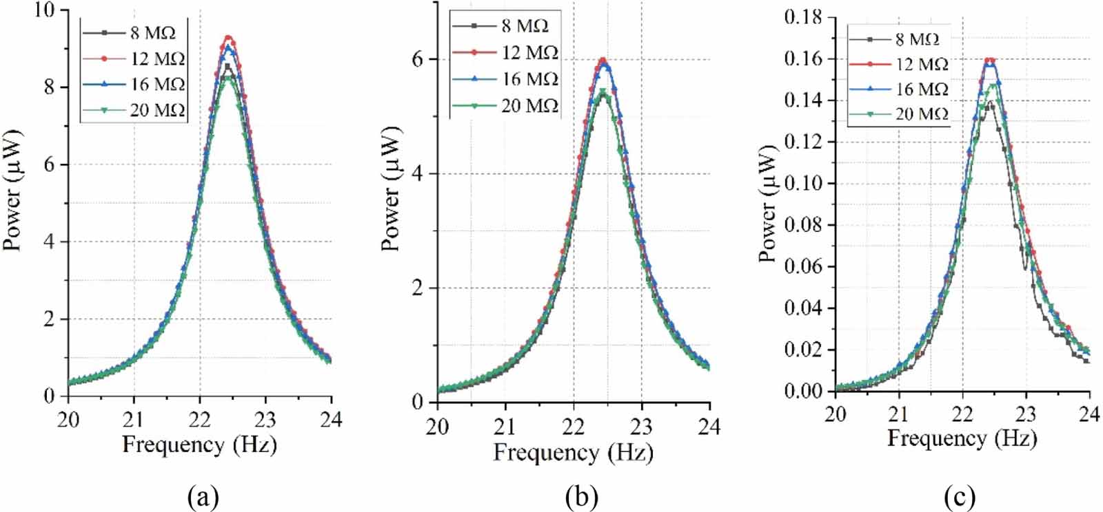
Standard image High-resolution imageOptimal impedance is a critical problem and essentially determines the maximum output power that can be obtained from a given energy harvesting system. Therefore, in addition to the open-circuit voltage response, figure 6 shows the power response with varying load resistance. For conciseness but without loss of generality, the results of only three cases with α = 0°, 45° and 90° are presented. For the ease of identification, only the results of four discrete resistance values are demonstrated in the figure. It is observed that regardless of the orientation angle α, the quasi-optimal resistance is the same for all the three cases: the maximum power outputs are achieved with the resistance of 12 MΩ. This is also understandable, since the change of the orientation angle α only indicates the change of the excitation condition but does not influence the system parameters.

Figure 6. Experimentally obtained power versus frequency for different load resistances around the fundamental resonance: (a) α = 0°, (b) α = 45°, (c) α = 90°, under the base excitation of 0.5 × g.
Download figure:
Standard image High-resolution imageIn addition to the fundamental resonance, the performance of the twist-beam VEH around the second resonance is investigated as well. Since the voltage output from a VEH at higher-order resonances is normally much smaller than that at the fundamental resonance, the acceleration is increased to 2 × g for the following study to make the results more easily recognizable. Figure 7 shows the corresponding results by sweeping the excitation frequency from 30 to 43 Hz. It is observed that for different α, the peaks in the power frequency response occur all around 41.47 Hz which is the second resonant frequency of the twist-beam VEH. It can be seen that the first two resonant frequencies of the twist-beam VEH are very close to each other and the ratio between them is less than 2. As well known that for a typical cantilever plain beam, the ratio between the second and the fundamental resonant frequencies is larger than 6. Therefore, compared with a conventional plain VEH, the first two resonant frequencies of the proposed twist-beam VEH can be more easily tuned within a targeted frequency range to form a wider operation bandwidth.

Figure 7. Experimentally obtained open-circuit voltage frequency response of the twist-beam VEH around the second resonance for different orientation angle α under the base excitation of 2 × g.
Download figure:
Standard image High-resolution image
From figure 7, one can note that different from the behaviour around the fundamental resonance, the open-circuit voltage amplitude of the twist-beam VEH increases with the increase of α. When α = 90° and 0°, the output voltage amplitudes are 11.07 and 2.74 V, respectively. This phenomenon can also be explained by the vibration mode analysis of the twist-beam VEH. For the vibration in the second mode, the dominant motion is in the direction perpendicular to the thickness direction of the plain segment. Hence, when α = 90° and 0°, the excitation directions are, respectively, in parallel with and perpendicular to the dominant motion of the twist-beam VEH. Obviously, the former case is expected to produce a higher voltage output. The similar behaviour around the second resonance, as revealed in figure 7, is that though the open-circuit voltage amplitude decreases with the increasing α, the voltage amplitude is always non-zero. Therefore, the multi-directional ability of the twist-beam VEH is also confirmed around the second resonant frequency.
Based on these results, the prospects on the further optimization of the twist-beam VEH are as follows. First, to improve the robustness of the multi-directional ability, it is preferred to have a relatively constant voltage output for different α. However, the variation between the voltage outputs of the current prototype at α = 90° and 0° is relatively large in the current prototype. To address this problem, one can attempt to enhance the coupling stiffness kxy (figure 1(c)) by decreasing the pitch of the helix that controls the pre-twisted shape, i.e. introduce more turns of helix over the same span. Second, the first two resonant frequencies are expected to be as close as possible. To this end, one also needs to manipulate the helix, since it is a critical factor that influences the resonant frequencies of the twist-beam VEH. In addition, further system optimization of the twist-beam VEH can be performed to increase the efficiency which reflects the real working performance [27].
6. Conclusions
In this letter, we have proposed a twist-beam VEH for multi-directional vibration energy harvesting. The underlying mechanism of the multi-directional ability of the proposed twist-beam VEH has been explained using the theory of a pre-twisted beam with coupled flexural vibrations. A simulation study has revealed the potential advantages of the twist-beam VEH as compared with a conventional plain beam VEH in terms of the multi-directional and multi-modal abilities. An experimental study has been conducted for further concept validation. The results have showed that regardless of the orientation angle of the twist-beam VEH (i.e. the excitation direction), the proposed twist-beam VEH can always produce a substantial amount of power. Moreover, it has been found that, the first and the second resonant frequencies of the prototyped twist-beam VEH are 22.37 and 41.47 Hz, respectively. Since the first two resonant frequencies can be more easily tuned within a targeted frequency range, as compared to a conventional plain beam VEH, the proposed twist-beam VEH demonstrates an excellent multi-modal energy harvesting ability.
Acknowledgments
The authors would like to thank Mr. Kunyong Lv for his assistance of designing and manufacturing the physical prototype using 3D printing technique.