

Abstract
Flapping wing applications require actuators that are light in weight and can produce large displacements. A piezoceramic coated flapping wing without any other amplification mechanism is developed for micro and nano aerial vehicles. The dragonfly wing shaped structure with the piezoceramic coating produced a lift of 0.99 mN which was 1.3 times the mass of the wing. The results obtained from the experiments to mimic the kinematic motions of the wing using the coated piezoceramic actuator are also reported.
Export citation and abstract BibTeX RIS
1. Introduction
Development of flapping mechanism for wings of micro- and nano aerial vehicles requires actuators that can generate large stroke. These actuators need to be lightweight, efficient and compact. Also, the integration of the actuator with the flying structure should be preferably easy and durable while providing high transduction efficiency [1–4]. For vehicles in the size range of insects, flapping flight is advantageous for its superior manoeuvrability and lifting capability at low flight speeds. Flapping wing systems, inspired by insect flight, generally involve the wing completing a complex set of motions over a flapping cycle [5] that includes pitching, yawing and sweeping. The flapping flight exploits electromechanical resonance, which significantly increases actuation efficiency. Various mechanisms such as pneumatic and motor-driven actuators have been employed to mimic this complex motion. But these mechanisms have severe disadvantages, such as heavy weight and mechanical system complexity. Fortunately, there are a number of unconventional methods that can be used for actuation, such as piezoelectric, thermal [6], electromagnetic [7], shape memory [8], etc. Out of them, the piezoelectric method is widely used for flapping mechanism due to its large bandwidth, large output force, compact size, and high power density [9, 10]. However, the deflection generated by a bending mode piezoelectric actuator in the bulk form is intrinsically small. Therefore, it is necessary to employ several types of motion amplification mechanisms to achieve large deflections. A micromechanical flying insect developed at the University of California, Berkeley employs a four-bar mechanism to amplify the displacement generated by the piezo patch to achieve the required wing stroke amplitude [2, 11]. Three different flexure based mechanisms were developed to transform the piezoelectric output for the electromechanical emulation of the mesoscale flapping flight [1]. Lightweight piezo-composite actuator was developed for mimicking the flapping wing system of insects. But this actuator also needed a four bar linkage system to improve the flapping amplitude [12]. Another motion amplification mechanism is the piezoelectric fan (piezofan) which couples a piezoelectric unimorph to an attached flexible blade and is capable of producing large deflections at resonance [13]. The design of such amplifying mechanisms is a complex procedure and also the components of the mechanism are included as an additional module to the overall subsystems of flight vehicle that adds to the overall weight. A few reports on applying the piezoelectric actuator for direct drive have also appeared. Directly driven flapping wing with piezoelectric unimorph actuator from a single crystal PIN-PMN-PT, is reported to achieve a lift force of about 1.9 times the weight of the actuator [14]. MEMS based flapping wing was developed with PZT thin film directly deposited by MEMS processing technologies. It demonstrated resonant flapping motion with a stroke amplitude of 44° [15]. However, the reported methods of fabrication of the wing are complex and need sophisticated manufacturing facilities to fabricate these wings and actuators.
Here, we have explored the use of a simple piezoceramic coating as an actuator without any other amplification mechanisms for flapping wing application. The piezoceramic coating as an actuator offers significant advantages such as light weight and surface conformality. Thin coating of thickness up to 30 μm can be easily achieved. The piezoceramic coating can be applied directly over any type of substrate such as a metal or a polymer. In this work a polymer is used as the wing substrate. Unlike the bulk piezoelectric actuator, the piezoceramic coating is flexible and can generate large displacements. It does not require a bonding or adhesive layer as the coating is applied in situ on the substrate. Further, we have measured the lift force it generates and find it to be sufficient for potential use in MAVs and NAVs.
2. Evaluation of piezoceramic coating
The schematic of the structure in the form of a cantilever beam of length (l) and width (w) is given in figure1 . Here, t is the thickness and the subscripts 's' and 'p' represent the substrate and the piezoelectric layer, respectively. Compliance and the thickness of the layer are expressed as s and t respectively. The transverse piezoelectric coefficient of the piezoelectric layer is given by d31. The permittivity of the piezoelectric layer is  p. The electromechanical behaviour of a piezoelectric actuated structure subjected to various electrical and mechanical forces is described by the relation [15, 16]:

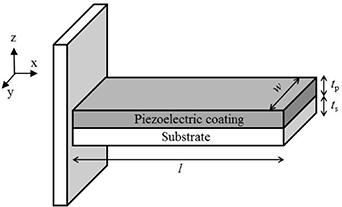
Figure 1. Schematic diagram of cantilever.
Download figure:
Standard image High-resolution imagewhere u, Q, F and V are the tip deflection, charge, tip force, and voltage, respectively. The real and imaginary parts of eiΩt represent a cosine and sine form of excitation, respectively. The coefficients C1(x), C2(x), C3(x) and C4(x) are given by
where  ,
,
and, the coefficient bn is obtained from the characteristic equation for a cantilever, i.e. cosh (bl) cos (bl) + 1 = 0. The subscript n represents the nth mode of vibration, m is the mass per unit length of the cantilever, and the damping ratio ςn is found using the standard relationship,
where the damping coefficient c is determined by logarithmic decrement using data from free oscillations of the cantilever.
The expression for the dynamic tip displacement u(l,t) for the beam is obtained as

The resonant frequencies (fn ) of the corresponding modes can be obtained using equation (5) as follows:

The propulsion of a flapping wing vehicle uses complex fluid dynamics [17]. Fortunately, the propulsion efficiency is related to a rather simple dimensionless number, the Strouhal number (St) that is frequently used in the analysis of oscillating, unsteady fluid flow. This number is expressed as St = fA/U, where f is the flapping frequency, A is the flapping amplitude, and U is the forward speed. The propulsive efficiency is high over a narrow range of St and usually peaks within the interval 0.2 < St < 0.4. It is found that most swimming and flying animals operate at 0.2 < St < 0.4 when cruising. This can be used for the prediction of cruising flight and swimming speed for animals as U = fA/St, and can also be used as a design guide for wing morphology and kinematics using fA= USt in flapping wing applications, where St≈ 0.3 [18]. The product fA (tip velocity, ν) is used by a few researchers as an optimization criterion for designing flapping wing actuators [12, 17]. The tip velocity ν for the first mode is given by

The induced elastic energy is expressed as [14]:
The air pressure on the wing is transformed into air flow energy Umech which is the source of the lift force. Thus, the ratio,χ of Umech to area density, can be used as an index of lift to mass ratio.
One of the most important figures of merit for electromechanical transducers is the electromechanical coupling coefficient, k. Generally, the square of k is used instead of k as it can be related to the lift-force-to-power efficiency. The expression for k2 for a piezoelectric actuator in dynamic operation is given by [19],
The complete details of the analytical model and the derivations of the above expressions are given in [14, 16, 19–21].
Given these indices, as expressed in equations (9), (11) and (12), the flexible piezoceramic coating is compared with the flexible piezoelectric material polyvinylidene difluoride (PVDF) for the flapping wing application. Their material properties are summarised in table1. Elastic modulus of the piezoceramic coating was obtained by tensile test of an unsupported film of piezoceramic material of 0.1 mm thickness made by spraying piezoceramic coating onto a polymer film, from which it was easily removed without damage [22]. The evaluation of d31 of piezoceramic coating was performed using the tip displacement measurement of the cantilever (length 50 mm, width 10 mm substrate thickness 0.09 mm and piezoceramic coating of 0.05 mm) actuated by a DC signal [21].
Table 1. Material properties of piezoceramic coating, PVDF and substrate.
| Properties | Piezoceramic coating | PVDF [23] | Substrate | |
|---|---|---|---|---|
| Young's modulus (GPa) | 3 | 2.8 | 6 | |
| Density (kg m−3) | 2300 | 1750 | 1440 | |
| Relative permittivity | 54 | 10 | – | |
| Transverse piezo coefficient, d31 (pm V−1) | −26 | −8 | – | |
We calculated the tip velocity ν/V using equation (9) in the range 0.01 ⩽ ts/tp ⩽ 100. Figure 2 shows the value of ν/V for piezoceramic coating and PVDF. The results indicate that the piezoceramic coating consistently shows larger ν/V compared to PVDF. Figure3 depicts the value of χ/V2 calculated from equation (11). For χ/V2 also, the piezoceramic coating gives larger values than its flexible counterpart PVDF.

Figure 2. Tip velocity as a function of the thickness ratio for piezoceramic coating and PVDF.
Download figure:
Standard image High-resolution image
Figure 3. Elastic energies per unit mass as a function of the thickness ratio for piezoceramic coating and PVDF.
Download figure:
Standard image High-resolution imageThe EMCF for the first mode (k1 2) was obtained using equation (12). A value of 0.018 is used for ς1, obtained from the experimental evaluation [20], in the k1 2 calculations. Piezoceramic coating shows a larger value of k1 2 than PVDF (figure 4). These results indicate that piezoceramic coating is a better flexible piezoelectric material for flapping wing applications.
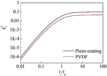
Figure 4. EMCF as a function of the thickness ratio for piezoceramic coating and PVDF.
Download figure:
Standard image High-resolution image3. Piezoceramic coated flapping wing
Wing planforms of insects with wing length around 45 mm, such as dragonfly (Aeshna juncea) [24], tobacco hawk moth (Manduca sexta) [25] and cicada (Oncotympana fuscata) [26], have been chosen in this work. The dimension of the wings are given in the table 2. As the flapping application makes use of mechanical resonance for efficient flight, the piezoceramic coating needs to generate maximum displacement at the first mode resonance. To achieve maximum displacement, we need to optimise the configuration of the piezoceramic coating. The tip velocity is used as the optimisation criterion. As the piezoelectric actuator forms an integral part of the wing structure, mere knowledge of the piezoelectric properties of the coating is not enough to design and fabricate the wing. Geometric variables such as wing shape, thickness and length of the piezoceramic coating influence the generated displacement at resonance. The effect of each variable is studied through finite element (FE) modelling.
Table 2. Dimensions of the wing planforms.
| Wing geometry | Wing length (mm) | Mean chord (mm) | |
|---|---|---|---|
| Dragonfly | 45 | 8.7 | |
| Hawk moth | 45 | 13.9 | |
| Cicada | 45 | 12.6 | |
The FE modelling of flapping wing was done using COMSOL multiphysics software. 3D model of the wing was built using AutoCAD and imported to COMSOL. The wings consist of two layers: the substrate and the piezoelectric layer. The properties of the substrate and piezoceramic coating materials used in the FE model are listed in table1.
The models were meshed with 3D prism elements. The number of elements for these models range from 9944 to 17 248. The mechanical boundary conditions appropriate for the cantilever beam model were applied, that is, zero displacement and rotation for the nodes at the clamped end of the beam. Electrical voltage was applied between the top and bottom faces of the piezoelectric layer of the model. The mesh discretization studies were carried out to obtain convergence with error less than 10–8. The optimized mesh was obtained when further mesh refinement resulted in a 3rd decimal place variation of the result (for displacements in mm). As this work does not require accuracy of micron level, further discretization was not considered necessary.
Initially, the FE model was validated by modelling a cantilever and verifying it through analytical model. A cantilever of length 50 mm and width 10 mm having a polymer substrate of thickness 0.09 mm coated with a piezoceramic layer of thickness 0.05 mm was modelled in COMSOL. The first mode resonant frequency and dynamic displacement at the first resonance were obtained. These results were compared with those for the same cantilever obtained using analytical equations (7) and (9). The results were found to be in good agreement with the maximum error of 0.4%.
A configuration similar to the cantilever beam is considered in the simulation where the root of the wing is fixed and the tip is free. An electric field is applied across the top and bottom surface of the piezoceramic coating. Free triangular meshing is used for the top layer of the piezoceramic coating and the same mesh is swept through the entire domain. A typical meshed geometry of the wing is shown in figure5. Solid mechanics interface and piezoelectric device interface of the COMSOL have been used in the simulation. The first mode resonant frequency (f1) and dynamic displacement at first mode resonance at the tip of the wing (u0) were determined from the FE simulation.
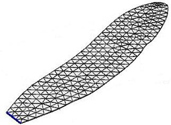
Figure 5. Typical meshed model of a wing.
Download figure:
Standard image High-resolution image3.1. Variation of wing geometry
Three different shapes of wings based on the planform of forewing of a dragonfly, a tobacco hawk moth and a cicada (figure 6) were modelled.

Figure 6. Solid models of (a) dragonfly wing (b) tobacco hawk moth wing (c) cicada wing.
Download figure:
Standard image High-resolution image3.2. Variation of thickness of the piezoceramic coating (tp)
The thickness of the piezoceramic coating is varied from 0.01 mm to 0.09 mm and the values of the first resonant frequency (f1) and the dynamic tip displacement (u0) are obtained using simulation. The entire wing planform was covered with piezoceramic coating while varying the thickness.
3.3. Variation of piezoceramic coating length (lp)
The length of the piezoceramic coating (lp) is varied from 0.05 mm to full wing length. The thickness of the piezoceramic coating was selected as 0.03 mm. The length of the coating was varied from the tip of the wing and also from the root of the wing. From FE model, the first mode resonant frequency (f1) and the dynamic displacement (u0) at the first resonance were obtained for various lengths of the coating from the root and the tip.
The results from the simulation along with those from experiments are discussed in the Results and Discussion section.
4. Experimental details
Several wing samples made of polymeric substrate with piezoceramic coating were prepared. Initially, a polymer substrate of 0.09 mm thickness was cut into the shape of the desired wing. Then, a thin silver electrode of approximately 100 nm thickness was evaporated over the polymer substrate to form the bottom electrode. The piezoceramic coating was applied over the electroded polymer substrates by covering one end for accessing the bottom electrode for electrical contact. Finally, a thin silver electrode of same thickness was evaporated over the piezoceramic coating as the top electrode. The prepared piezoceramic coated wings (figure7) were poled to near saturation with uniform electric field of 32 kV cm−1 for 30 min. For experiments, the root of the wing was clamped using teflon vise grip in order to facilitate dynamic measurements. The teflon vise was used since it provides non-conducting and non-damaging grip to the sample.

Figure 7. Photograph of fabricated flapping wings (a) dragonfly wing (b) tobacco hawk moth and (c) cicada wing.
Download figure:
Standard image High-resolution imageSchematic representation of measurement set up is given in figure8. Piezoceramic coating was actuated by a signal given from a function generator and applied between the top and the bottom electrode. The tip displacement was measured using a laser displacement sensor (Riftek RF-605) whose output was connected to an oscilloscope.

Figure 8. Schematic representation of the measurement set up.
Download figure:
Standard image High-resolution imageThe first mode resonant frequency (f1) of the wing was measured by actuating the wing with a sine sweep signal of 50 Vpp. The dynamic displacement of the wing tip (u0) was measured by actuating the wing with a sine signal of frequency f1 and amplitude 50 Vpp.
4.1. Measurement of lift
A schematic representation of the measurement set up for measuring the lift force is shown in figure9. The piezoceramic coating was actuated by a signal from the function generator and applied between the top and the bottom electrode. The measurement of lift of the flapping wing was done using a load cell of 100 g capacity with a resolution of 5 mg (Huazhun 651 C). The flapping wing was fixed on the load cell and the piezoceramic coating was actuated using the function generator. The reaction force generated on the fixed side of the wing while flapping was measured using the load cell. The output of the load cell was acquired using a DAQ card and a PC [27]. The measurement was carried out at the sampling rate of 2000 samples per second.

Figure 9. A schematic of the lift force measurement set up.
Download figure:
Standard image High-resolution image5. Results and discussion
5.1. Variation of wing geometry
Summary of the FE modelling and experimental results obtained for different wing geometries are shown in table 3. The wing with the dragonfly forewing shape showed the maximum value for ν at 114.7 mm s−1. The ratio of the tip velocity per unit area of the wing, ν/A, is also mentioned in the table.
Table 3. Summary of the modelling and experimental results obtained for different wing geometries.
| Wing geometry | FE model | Experiment | ||||||
|---|---|---|---|---|---|---|---|---|
| f1 (Hz) | u0 (mm) | υ (mm s−1) | f1 (Hz) | u0 (mm) | υ (mm s−1) | υ/A (mm.s)−1 | ||
| Dragonfly | 11.8 | 9.8 | 115.6 | 11.7 | 9.8 | 114.7 | 0.29 | |
| Hawk moth | 13.3 | 4.7 | 62.5 | 13.0 | 4.5 | 58.5 | 0.09 | |
| Cicada | 16.5 | 6.2 | 102.3 | 16.2 | 5.8 | 94.0 | 0.16 | |
As the maximum values of ν and ν/A, are obtained for the dragonfly wing, further variation in the geometrical parameters were studied for this wing. While studying the variation in geometrical parameters, the ratios of lengths and thicknesses of the piezoceramic coating and the substrate are used in order to have dimensionless parameters and scale versatility.
5.2. Variation of thickness of piezoceramic coating (tp)
Dragon fly shaped wings with piezoceramic coating of thicknesses 0.03, 0.04 and 0.05 mm and substrate of thickness (ts) 0.09 mm were fabricated and tested. The results for the tip velocity from the FE model and experimental measurements are shown in figure10. It can be inferred that for the given substrate thickness, a thinner piezoceramic coating gives the maximum tip velocity.

Figure 10. Tip velocity as a function of the thickness ratio of the substrate and the piezoceramic coating.
Download figure:
Standard image High-resolution image5.3. Variation of the piezoceramic coating length (lp)
The length of the piezoceramic coating, lp, is varied from the root and then from the tip of the cantilever. The plots of tip velocity vs ls/lp, is shown in figure11. The thickness of the piezoceramic coating was 0.03 mm for all lengths. When the entire length of the wing is covered with the piezoceramic coating, the maximum dynamic displacement is obtained. The maximum value for ν of 123.2 mm s−1 was obtained for the length of piezoceramic coating of 30 mm from the root. From the plot, it can be inferred that for the same length of the piezoceramic coating which covers the substrate from the root gives more displacement than the coating that covers the substrate from the tip. In figure11(a), there are two values of ls/lp between 1 and 2 that give the same tip velocity. Given that the maximum tip velocity is obtained when ls/lp ∼ 1.5, it is clear that a longer coating than 2/3 of the wing length reduces the tip velocity by producing stress that partially counters the desired effect. This is well understood and reported for different topologies of piezoactuators in the literature. For ls/lp > 2, the tip velocity is single valued. In figure11(b), for ls/lp > 2, the tip velocity approcahes zero as the actuation becomes ineffective giving rise to a seemingly constant value for the tip velocity for several values of ls/lp.
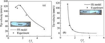
Figure 11. Tip velocity vs the ratio of lengths of the substrate and the piezoceramic coating (a) from the root of the wing (b) from the tip of the wing (Inset: Photographs of typical wings with piezoceramic coating (a) from the root of the wing (b) from the tip of the wing).
Download figure:
Standard image High-resolution image5.4. Measurement of lift-force
When the flapping wing was actuated at the resonant frequency, the lift was measured by using the load cell [27]. The mean lift-force of 0.99 mN (figure12) was obtained for the dragonfly wing which turns out to be 1.3 times the weight of the wing.For hawkmoth wings the lift force was measured to be 1.15 mN and for cicada wings it was 0.95 mN. The lift to weight ratio for the hawkmoth and cicada wings are 0.91 and 0.82 respectively.

Figure 12. Lift-force measured for the dragonfly wing.
Download figure:
Standard image High-resolution imageTable4 compares the details of the flapping wings actuated by piezoelectric based actuators. From table4, we can infer that the piezoceramic coating is a potential actuator for flapping wing applications. Most of the piezoelectric based actuators employ amplification mechanism. But piezoceramic coating actuators is directly applied on the flapping wing thus minimising the complexity of the system.
Table 4. Summary of flapping wings actuated by piezoelectric based actuators reported.
| Ref | Size | Actuator | Lift generated (mN) | Mass | Lift to weight ratio | Vehicle flight | Amplification mechanism |
|---|---|---|---|---|---|---|---|
| [28] | Wing span—30 mm | Piezoelectric bimorph | 1.30 | Vehicle mass- 80 mg | 1.65 | Achieved | Flexure based mechanism |
| [29] | Wing span—30 mm | Piezoelectric bimorph | – | Vehicle mass—60 mg | Achieved | Transmission mechanism | |
| [30] | Wing span—122 mm | Lightweight piezo-composite actuator (LIPCA) | 3.24 | 10.28 g | 0.03 | – | Linkage system |
| [31] | Wing length—90 mm | Piezoelectric THUNDER TH-8 R | 5.35 | Mass of the wing 270 mg | 2.01 | – | Rotor system |
| [15] | Wing length—1.5 mm | PZT thin film | – | – | – | – | – |
| [32] | Wing span—25 mm | PZT unimorph | 1.40 | – | – | Achieved | Four bar mechanism |
| [33] | Wing span—114 mm | PIN-PMN-PT | 6.52 | Prototype mass—598 mg | 1.11 | Tethered flight | – |
| [34] | Wing span 37.5 mm | PZT T beam | 1.34 | – | – | – | Revolute joints and hinges |
| [35] | Wing length 30 mm | PZT—5 H beams | 6.03 | Mass of the wing 31.5 mg | 19.82 | – | Robotic transmission mechanism |
| This work | Wing length—45 mm | Piezoceramic coating | 0.99 | Wing mass—78 mg | 1.30 | – |
6. Kinematics of the wing
Insects use a variety of wing beat kinematics to produce and control aerodynamic forces for flight. They manipulate many aspects of the wing motion such as stroke amplitude, stroke frequency, the angle of attack and stroke plane. They also actively control the timing between the fore- and hind-wing stroke cycles during turning manoeuvres [17, 36]. While mimicking an insect flight, the selected actuator needs to be capable of producing insect flight kinematics. The novelty of our work is on integrating an actuator in the form of a thin piezoceramic coating on the wing itself, thus obviating the need for additional mechanical mechanisms as is prevalent in the literature. Our emphasis here is on demonstrating the feasibility of actuating the motions of the wings (both flapping and twisting) with this thin coating, and not on obtaining the highest possible stroke lengths or flapping angles. We show that using the piezoceramic coating these motions can be achieved by controlling the input electric signal to the piezoceramic coating actuator. We were able to achieve twisting motion and phase difference between the fore- and hind-wings kinematics using this novel actuator. These results are reported here.
6.1. Twisting motion
Twisting motion of the wing was achieved by actuating two piezoceramic coating actuators in the cantilever form out of phase. Initially, the cantilevers made of polymer of 0.09 mm thickness and piezoceramic coating of thickness 0.03 mm with 40 mm length, 4 mm width were fabricated. A thin polymer film of thickness 0.04 mm thickness in the shape of the dragonfly wing was stuck over the cantilevers as shown in figure13. These cantilevers were actuated by sine wave signals of 13 Hz frequency with 50 Vpp amplitude which were out of phase by 180° and generated by the function generator.

Figure 13. Fabricated wing with two cantilever to produce twisting motion.
Download figure:
Standard image High-resolution image6.1.1. Results.
The displacement of the wing was measured along the chordat about 8 mm from the tip. The two points of measurements (red dots) are shown in figure13. Twisting motion about the wing axis with a maximum amplitude of 3 mm was produced by actuating the cantilevers with 180° out of phase signals.
6.2. Forewing and hindwing kinematics
Two wings in the shape of the dragonfly wings (forewing and hindwing) were fabricated with polymer substrate of thickness 0.09 mm with thick 0.03 mm piezoceramic coating. Fore wing and hind wing were actuated by identical sine waves of 11 Hz frequency with 30 Vpp amplitude but out of phase with each other. Signals with phase difference of 0°, 90°, 180°, 270° were applied to the wings and the tip displacements were measured.
6.2.1. Results.
Tip displacements of 4 mm for the forewing and 3 mm for the hindwing were measured. Figure 14 shows the images of actuation at different phases of actuation in a single cycle when the fore-wing and the hind-wing were actuated at 180° phase difference. The stroke amplitude of ∼±2.5° was achieved for the wings. We are clearly far from what nature can do, but further improvements in both design and material properties can take us there.

Figure 14. Images of the wings, captured from a video, at different phases of actuation in a single cycle when the fore-wing and the hind-wing were actuated at 180° phase difference (picture of the ruler is given for reference). Considering the fore-wing actuation as V= V0 sin(ωt + ϕ), the images correspond to (a) t = 0.0225s, ϕ = 90° (the vertical separation between the two wings is minimum) (b) t = 0.03375s, ϕ = 135° (c) t = 0.045s, ϕ = 180° (d) t = 0.05625s, ϕ = 225° (e) t = 0.0675s, ϕ = 270° (the vertical separation between the two wings is maximum).
Download figure:
Standard image High-resolution image
7. Conclusions
We developed piezoceramic coating actuators without any other amplification mechanism for flapping wing applications. The performance indices specifc for flapping wing application were evaluated for piezocoating and compared with another flexible piezoelectric material PVDF. These indices for piezocoating were found to be better. The configuration of the piezoceramic coating to achieve the maximum tip velocity was obtained through optimisation process through FE modelling. The flapping wing with the dragonfly forewing shape is shown to generate the maximum tip displacement. Based on the FE simulations, the thickness ratio of polymer substrate and piezocoating for maximum tip velocity was found to be 9. These simulations also gave the optimal value of piezocoating length as a fraction of wing length to be 1. We conducted experiments with different thickness and length ratios to validate the simulation results. We used the optimal value of ts/tp = 3 and ls/lp = 1 for fabricating a wing of length 45 mm and with piezocoating of thickness 0.03 mm for finding the lift force generated by the piezocoating actuator. The maximum tip displacement at the wing's first resonant frequency was measured to be 22% of the wing length. This results into a tip velocity of 114.7 mm s−1 which is 7.8% of a dragonfly's average tip velocity. At this tip velocity the measured lift force is 0.99 mN which is 1.3 times the weight of the wing. These experiments with the measured parameters show a promising future for incorporation of these piezocoating actuators in flapping wing applications simply by coating the wings with the piezoceramic material of appropriate thickness and length.
In order to harness the benefits of the novel actuation demonstrated here, further efforts on optimizing the wing structure for reducing its mass (both substrate and the coating) and increasing the stroke amplitude, flapping frequency and the generated lift, are required. It is obvious that a lot more work is needed for figuring out the complete kinematics of the wing in response to varying actuation signals to both pairs of fore and hind wings which will eventually lead to a complete control of the wing dynamics along with that of the MAV.
Acknowledgments
Bhuvana N, acknowledges the support of Mr. Antony Jeyaseelan A, Senior Research Fellow, Materials Science Division, CSIR-NAL for the preparation of piezocoating for wing structure. She also acknowledges the support of staffs at Center for Nano Science and Engineering, Indian Institute of Science.