Properties of Micro-Arc Oxidation Coating Fabricated on Magnesium Under Two Steps Current-Decreasing Mode
 Ze-Xin Wang
 Jin-Wei Zhang1
  Sheng Lu
- 1School of Materials Science and Engineering, Jiangsu University of Science and Technology, Zhenjiang, China
- 2Zhenjang Naisi Advanced Materials Co., Ltd., Zhenjiang, China
A concept of two-steps current-decreasing mode derived from constant current mode was developed to fabricate micro-arc oxidation (MAO) coatings on ZK60 magnesium alloy in a dual electrolyte system. The growth characteristics of coatings were analyzed by voltage-time curves, and the coating microstructures were characterized by means of scanning electron microscopy. Meanwhile, the roughness, corrosion behavior, and microhardness of MAO coatings were investigated. The results show that the MAO coatings exhibit a smooth and compact surface, and have improved hardness, higher thickness, smaller roughness, and uneven distribution of holes. Such positive characteristics result in improved corrosion resistance of MAO coatings. The coating produced under the two-steps current mode of “1.2–0.6A” shows a smaller corrosion rate of 0.1559 g/m2⋅h compared with the one produced under the other mode. The results of nanoscratch tests show that the coating fabricated by “1.2–0.6 A” mode has strong bond strength with the substrate. Under this optimized mode, the MAO process also has the lowest energy consumption of 49.8 W/(dm2⋅μm).
Introduction
For their good mechanical and thermal properties, magnesium and its alloys have attracted more and more attention in many industrial fields, such as automobile, aerospace, and medical instruments (Pan et al., 2018; Ramalingam et al., 2019; Venkatraman and Swamiappan, 2020). Nevertheless, the application of Mg alloys is largely limited due to its poor corrosion resistance. In order to expand their applications, an available solution should be worked out to solve the problem of the alloy’s poor corrosion resistance (Goli and Aghajani, 2018; Ren et al., 2018; Yang et al., 2018; Pan et al., 2019, 2020; Kuang et al., 2020; Sun et al., 2020). Generally, an effective way to improve corrosion resistance of alloy is to synthesize a protective coating on the surface of Mg alloys. In the past several decades, many surface modification technologies have been used on magnesium alloys, including anodic oxidation, ion implantation, electroless plating, techniques of chemical conversion coatings. Cai et al. (2009) produced an in-depth study about anodic oxidation of magnesium including the corrosion mechanism of active dissolution, passivation and secondary oxidation of magnesium in 6 M KOH solution. During the experiment, it was found that changing the electrical parameters does not significantly improve the corrosion resistance of the film. Jin et al. (2015) reported that the corrosion resistance of WE43 magnesium alloy can be improved by ion implantation of a small amount of Nd. The results showed that this method significantly retarded the degradation of WE43. Furthermore, significantly enhanced cell adhesion and excellent biocompatibility of WE43 are observed after Nd ion implantation. However, the safety of rare earth elements in biomedical magnesium alloy is still in the research stage. Shao et al. (2017) reported that using nickel hydroxide as the main salt for electroless nickel plating can improve the corrosion resistance of AZ91D magnesium alloy. However, electroless nickel plating still has some problems, such as insufficient environmental protection of waste liquid (Wang et al., 2014). Other surface modification technologies also have different disadvantages (Forero López et al., 2018; Zang et al., 2020). Recently, the micro-arc oxidation (MAO) technique, which is derived from the traditional anodic oxidation, has been employed as an advanced technique to modify the surfaces of Mg alloys (Zhang and Chen, 2019; Zhang et al., 2020). During the MAO process, the specimens work as the anode and the electrolyte pool works as the cathode. When applying a high voltage between two electrodes, the intense spark discharge would take place on the surface of the specimens (Patcas and Krysmann, 2007; Wang et al., 2011). Due to the local high temperature caused by discharge and the involvement of thermal-, plasma-, and electro-chemical reactions in the electrolyte, ceramic-like coatings can be fabricated on the surfaces of the specimens with good compactness, corrosion resistance and wear resistance (Lee et al., 2019; Li et al., 2019; Zhu et al., 2019).
The properties of MAO coatings are strongly influenced by many factors, such as power types, control modes, process parameters (such as current density, frequency, and duty cycle, etc.) and the compositions of electrolytes (by altering the compositions of the electrolyte, the phase constituents of the coating can be adjusted). More excellent coatings can be obtained by adjusting the factors that affect the properties of the coatings. For instance, Zhang et al. (2012) investigated the effect of different voltages (250, 300, and 350 V) on the properties of MAO coatings on AZ31 Mg alloy, and found that the MAO coating prepared at 250 V has better corrosion resistance compared with the counterpart prepared at the other voltages. Lv et al. (2008) studied the effect of current frequency (100 and 800 Hz) on the morphology and corrosion resistance of MAO coatings on ZM5 Mg alloy. Their results showed that the MAO coating prepared at 100 Hz has a rough surface with large pores and exhibits poor corrosion resistance, which might be triggered by the sparks at the same location for a long time during the MAO process. Much of the research investigating MAO coatings on Mg alloys has focused on the optimization of electrical parameters to improve their corrosion resistance (Sobrinho et al., 2017). It is also necessary to control the electric parameters during the MAO processes.
Current density during the MAO process is generally regarded as an important electric parameter. Our group has previously completed research on the growth mechanism at low-current (Chen et al., 2015). In previous works, it can be found that the structure of these coatings and the voltage curve would change significantly as time goes by (Jiang et al., 2013; Yao et al., 2013; Dehnavi et al., 2015; Sobrinho et al., 2017). Although it is easy to calculate and control the energy consumption using the constant current mode, too much energy input can cause these coatings to peel off during the final repairing stage. Besides, the corrosion resistance of these coatings would deteriorate while the current increases during the final repairing stage, which is attributed to low compactness of coatings and uneven distribution of pores (Ly and Yang, 2019). Therefore, there is a new method proposed for the first time in this work, which uses a low current in the final repairing stage, namely, the two-steps current decreasing mode.
ZK60 is a high-strength deformed magnesium alloy. The related research was mainly focused on its plasticity and high-strength mechanical properties. The reported regarding surface corrosion protection of ZK60 was rare. The corrosion resistance and wear resistance of ZK60 still limit its application. In this work, a new and promising micro-arc oxidation surface treatment technology was used to modify the surface of ZK60. MAO coatings were fabricated using two-steps current-decreasing mode, which aims to reduce the energy input by decreasing the current in the final repairing stage. During the first stage, high energy input should be given, which could be conducive to the breakdown of passive film under the constant current mode. During the second stage, low energy input could obtain a preferable repairing effect. Furthermore, scanning electron microscopy (SEM) and laser scanning confocal microscopy (LSCM) were used to examine the morphologies of the coatings. X-ray diffraction meter (XRD) was employed to investigate the phase constituents of the coatings. The bond strength between coating and substrate was evaluated by nanoscratch tests. Likewise, the corrosion behavior of the MAO coatings was investigated by electrochemical tests.
Materials and Methods
Preparation of MAO Coating
ZK60 commercial deformed magnesium alloy was used in this experiment, which has undergone solution and aging treatment after deformation. It has been reported that the ZK60 magnesium alloy combined by deformation and aging treatment could enhance its yield strength (Song et al., 2013). Rectangular specimens (20 mm × 20 mm × 5 mm) were used as the anode, the compositions of ZK60 used in this work are shown in Table 1. Before the MAO treatment, the surface of specimens was ground with 800, 1,500, 2,000 grit SiC paper and ultrasonically cleaned with acetone for degreasing. Then, the specimens were rinsed with distilled water and dried in ambient air. The main precipitates of ZK60 are α-Mg phase and equilibrium Mg-Zn phase (Chen H. B. et al., 2016; Zeng et al., 2018).

Table 1. Compositions of ZK60 Mg alloy (wt%).
The MAO device was composed of a WHD-20 bipolar pulsed DC power (Harbin, China) and a stainless-steel bath containing electrolyte. In this work, a stirring system and a cooling system maintained the temperature of the electrolyte at 35–40°C in all cases. A composite electrolyte, which was composed of 17.5 g/L Na2SiO3, 5 g/L Na3PO4, 5 g/L NaOH, 3 g/L Na2B4O7, and 4 g/L C6H5Na3O7, was prepared for the MAO process. The MAO process was respectively carried out by two modes. One was constant current mode and the other was two-steps current-decreasing mode. For constant current mode, the electric parameters were set as follows: current of 1.2 A, frequency of 500 Hz, duty cycle of 40% and oxidation time of 900 s, which were the optimized results in our previous work (Wang et al., 2018). For two-steps current-decreasing mode, MAO process could be divided into two steps according to the voltage-time curves. On the first step (0–300 s), the current was set as 1.2 A. On the second step (300–900 s), the used current (1.2 A) was reduced to 0.6, 0.8, and 1.0 A, respectively. The specimens processed under two-steps current-decreasing mode were using these current parameters. Meanwhile, the frequency and duty cycle were the same as all specimens either under constant current mode or under two-steps current-decreasing mode. In order to simplify the discussion, hereafter, we label the four different current modes as 1.2 A mode, 1.2–1.0 A mode, 1.2–0.8 A, mode and 1.2–0.6 A mode, respectively.
Calculation of Current Density
The voltage-time curves were recorded automatically in PC during the MAO process. The current density is often regarded as an important parameter that affects the corrosion resistance of the coatings and reveals the electrical energy applied to the surface of the specimens (Ezhilselvi et al., 2016). To directly represent the corresponding current density of the specimens under different currents, the amount of current can be converted into current density according to the equation below, and the results are shown in Table 2.

Table 2. The conversion relationship between current and current density.
Where J is current density (A/dm2); I is the current in a stage (A); S is the total surface area of the specimen (dm2).
Immersion Test of Coatings
An electronic balance with an accuracy of 0.001 g was used to weigh the mass of the MAO specimen before immersion, which was recorded as W0. The specimen was immersed in a 3.5 wt% NaCl solution for 72 h and then taken out. Then, the specimen was put in the distilled water by ultrasonic cleaning for 10 min to clean the corrosion product. After drying, the mass of the specimen after immersion was weighed and recorded as W1.
The average corrosion rate of the coating was calculated according to formula (2).
Where V is the average corrosion rate of the coating (g/m2⋅h); W0 and W1 has been explained above; S is the exposed surface area of the specimen (m2); t is the test time (h).
Characterizations
The microstructures of the coatings were observed by SEM equipped energy-disperse spectroscopy (EDS) (JSM-6480, JEOL, Tokyo, Japan). Phase constituents were examined by XRD using a Shimadzu XRD-6000 with CuKα radiation operated at 40 kV. The parameters of 2θ range of 20°–80° and scan rate of 4°/min were set in this work. The roughness of the coated specimen was examined by a laser scanning confocal microscope (OLS4000, Olympus, Tokyo, Japan), which was used to measure the line roughness on the specimen surface. The final roughness data was gotten from the average value of five measurements. Image J2.0 software was used to calculate the coating porosity (Chen L. Y. et al., 2016; Chen et al., 2018b, 2019a). Microhardness of the coating was measured by means of a KB30S German automatic hardness tester. Nanoscratch tests were carried out using the scratch option available in the CSM-NHT2 machine platform equipped with a Rockwell indenter with a 100 μm tip radius. The corrosion resistance was characterized by CS2310 electrochemical workstation (CorrTest, Wuhan, Hubei, China) at the frequency ranging from 10–2 Hz to 105 Hz with a low amplitude alternating current amplitude of 5 mV in 3.5 wt.% NaCl solution. ZSimpWin software was used for fitting the EIS data. Error bars were calculated from the data of four specimens, which were used in results of roughness, thickness, microhardness, and corrosion rate.
Results and Discussion
Evolution of Voltage During MAO Process
To examine the effect of process parameters on coatings produced under a constant current mode, the voltage output is measured during the MAO process. This voltage output usually is presented as a curve with a number of distinct regions signifying various stages in the development of the coating. The voltage-time curves under different processing modes are revealed in Figure 1. Apart from the single constant current mode, the other three curves were obtained by respectively decreasing the current to 1.0, 0.8, and 0.6 A.
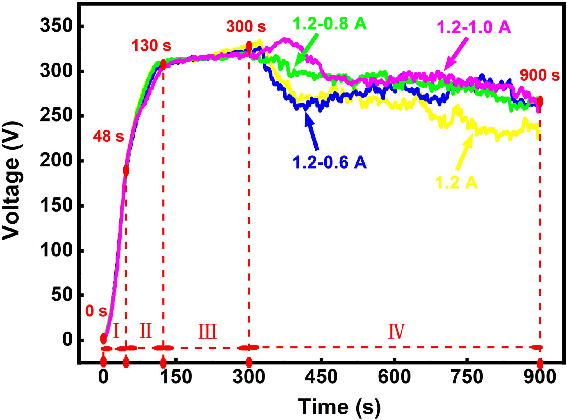
Figure 1. Voltage-time curves during the MAO process under different current modes.
All the curves can be roughly divided into four stages. At the first stage (0–48 s)—anodic oxidation stage, the slope of the curves remains basically invariable and the voltage increases linearly, indicating the formation of a very thin oxide film on the surface of the substrate. With the voltage rising up to about 175 V, the MAO process enters the second stage (48–130 s)—initial arc stage. In this stage, the slopes of the curves decline and arc discharge occurs on the specimen surface and micro-arc oxidation. The third stage (130–300 s) is the major stage for the growth of the MAO coating. The change of the voltage curves is slight in this stage. At the final stage (300–900 s)—coating repairing stage, the voltages change diversely under different current modes.
At the final stage, it can be observed that the voltage under 1.2 A mode decreases continuously and does not show stability over time, while the voltage under two steps current-decreasing mode drops sharply and then stabilizes. The descent of the voltage is most noticeable in 1.2–0.6 A mode, which is similar to the constant current mode. The voltage under 1.2–0.8 A mode drops inconspicuously. The voltage of the 1.2–1.0 A mode continues increasing at the beginning of the final stage and then decreases. The voltage value between 300 and 900 s was taken to calculate the average voltage at this stage. The values of the average voltages in this stage are about 263 V (1.2 A), 278 V (1.2–0.6 A), 288 V (1.2–0.8 A), and 296 V (1.2–1.0 A), respectively. As seen in the values of the average voltages, the number is the minimum among these values under the constant current mode. This implies that the average breakdown voltage is the lowest under 1.2 A mode. Furthermore, the reaction in the electrolyte would continue to weaken due to the decrease in the subsequent voltage. In the two-steps current-decreasing mode (1.2–0.6 A, 1.2–0.8 A, and 1.2–1.0 A mode), there is no obvious difference in the voltage after 600 s. The subsequent voltage at the final stage provides a more stable breakdown force for the MAO coating growth, which is in the lower current environment. Excessive current input would aggravate the crack propagation in the coating, which causes the coating to peel off (Yahalom and Zahavi, 1970; Ly and Yang, 2019). However, the peeling of these coatings may be suppressed due to the low current. The stable voltage means the stable breakdown force, and the low current input means a low energy input, which plays an important role in repairing the weak areas (Lu et al., 2011).
Unit Energy Consumption
The voltage variation of the different current mode takes place after 300 s due to the current accommodation. Eunit is referred to the unit energy consumption of the specimen surface in the final stage, which is calculated by Eq. (2). The energy consumptions for the growth of the coatings as a function of unit time and unit area are listed in Table 3. The meaning of J has been explained in Eq. (1). In the final stage, the adjusted current I and specimen surface area S can be regarded as stable values, hence J can also be regarded as a constant. The Eunit is mainly affected by voltage and the coating thickness. It can be seen that the Eunit in the final MAO stage is reduced under two-steps current-decreasing mode. The lowest Eunit under the mode of 1.2–0.6 A is 49.8 W/(dm2⋅μm). There are three reasons accounting for the above results.
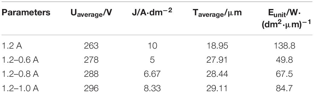
Table 3. Unit energy consumption of different current modes in the final stage.
The first reason is the current density. The adjusted currents are lower under the two-steps current-decreasing mode as well as the current densities, which is calculated by the Eq. (1). It can be seen from Table 3 that the current density J in the 1.2–0.6 A mode is only 50% of the 1.2 A mode, the corresponding calculated energy consumption Eunit is lower.
The second reason is the coating thickness. The increased thickness of the coating has become an important factor influencing the Eunit under the two-steps current-decreasing mode. The slow growth of the average coating thickness would increase the unit energy consumption under the constant current mode. It has been reported that the thickening of coating is the accumulation of the melts (Barati Darband et al., 2017; Peng et al., 2019). All sorts of elements enter the discharge channel to form a melt by high temperature and high pressure, and then accumulate in the channel under the cooling effect of the electrolyte (Krysmann et al., 1984; Chen et al., 2010). Increased thickness of coating would lead to the increase in the electrical resistance, which elevates the required voltage for the spark discharge on the surface of the specimen.
The third reason is the average voltage in the final stage. The voltage under the two-steps current-decreasing mode is higher than that under constant current mode in Figure 1, which has a positive effect on repairing the defects in the coatings. Sufficient breakdown force provided by the high voltage in the final stage supplies the reaction on the coating surface (Lin et al., 2013).
According to the analysis above, the two-steps current-decreasing mode can effectively reduce energy consumption and have a positive effect on the coating thickening.
where Uaverage is the average voltage during the MAO process (V); Taverage is the average thickness of the coating (μm); Eunit stands for the unit energy consumption [W/(dm2⋅μm)]; J, I, and S have been mentioned in section “Unit Energy Consumption.”
Microstructural Features
XRD Results
Figure 2 shows the XRD spectra of MAO coatings under different current modes. The phase constituents of four coatings mainly consist of Mg2SiO4, Mg, Mg2Si, and MgO phases, which are in agreement with previously reported results processed in a silicate-containing electrolyte (Durdu et al., 2013). In Figure 2, the increase in the peak intensity of these phases is found because the coating thickness increases under different power modes. The phases of Mg and MgZn2 mainly come from the substrate. It has been reported that a complex micro-arc oxidation reaction takes place in the melts to form not only the crystalline substance, but also high temperature phases in the discharge channel (Chen et al., 2010). MgO is derived from the passive film formed in the anodizing stage and the subsequent diffusion of Mg2+ and O2– between metal/film and film/electrolyte interfaces (Guo et al., 2006; Durdu et al., 2013). The participation of Mg2SiO4 in the passive film can increase it corrosion resistance (Wu et al., 2007). Compared with the constant current mode, it can be seen from Figure 2 that Mg2SiO4 phase exists in the coating, which is produced under two-steps current-decreasing mode and has a higher diffraction peak. Mg2SiO4 also belongs to the high temperature phase, and its formation process follows the reactions below:
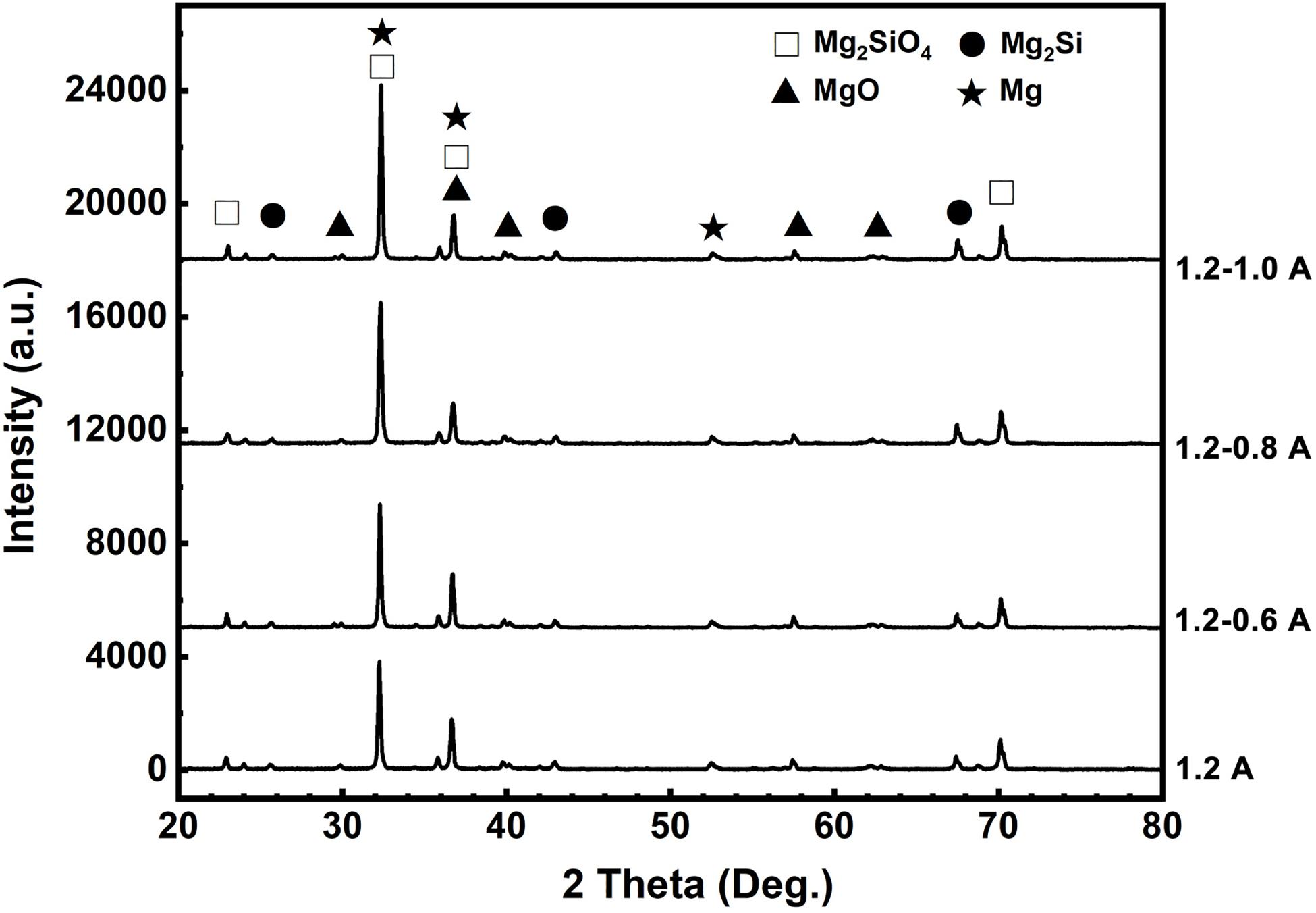
Figure 2. X-ray diffraction patterns of the MAO coatings fabricated under the different current modes.
Surface Morphologies of MAO Coatings
Figure 3 presents the surface morphologies of the MAO coatings obtained under different current modes. As seen from Figure 3a, a few of the larger pores with a size of 4–6 μm are presented on the surface of the coating under constant current mode (1.2 A mode). The calculated surface porosity is shown in Table 4. The porosities of four specimens are 2.47, 5.72, 6.33, and 7.84, respectively. It can be seen that the specimen under 1.2–0.6 A mode has a lower porosity. The specimen under 1.2 A mode has the smallest porosity but the surface cracks are more obvious. Compared with 1.2 A mode, 1.2–0.6 A mode has a smoother surface morphology. The pores are formed simultaneously with the occurrence of spark discharge during micro-arc oxidation (Lu et al., 2011; Chen et al., 2012; Wang et al., 2013). Continuous cracks are presented on the entire surface which has been covered by the surrounding solidified melts. The solidified melts are spouted and formed around the pores through the discharge channel by the cooling effect of the electrolyte (Xin et al., 2006; Zhang et al., 2006a; Rabadia et al., 2019). It should also be noted that the great thermal stress resulted from the rapid solidification of molten oxide accounts for the appearance of cracks (Niu et al., 2016; Santos et al., 2017; Chai et al., 2018; Chen et al., 2019b). Under the two-steps current-decreasing mode (Figures 3b–d), the solidified melts around cracks can still be observed, while the cracks are discontinuous and their quantity is not as same as on the specimen prepared under 1.2 A mode.
Figure 3. Surface morphologies of coatings under different current modes: (a) 1.2 A; (b) 1.2–0.6 A; (c) 1.2–0.8 A; (d) 1.2–1.0 A.
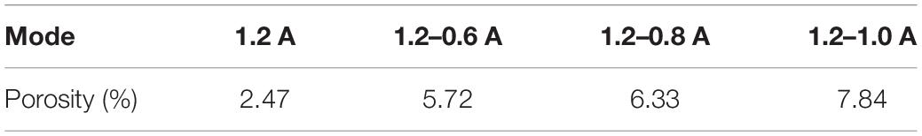
Table 4. Specimen surface porosity fabricated under the different modes.
Cross-Sectional Morphologies of MAO Coatings
Figure 4 shows the cross-sectional morphologies of MAO coatings under different current modes. The thickest part in the cross-sectional image is measured, which represents the limited thickness of the coating obtained by the MAO process. As seen from the Figure 4, thicknesses of these coatings are 17.4 μm (1.2 A), 27.1 μm (1.2–0.6 A), 28.7 μm (1.2–0.8 A), and 32.7 μm (1.2–1.0 A), respectively. It can be found that all the coatings are characterized as the dense inner layer and the porous outer layer with a distinguishable boundary. The coating fabricated under 1.2 A mode has the minimum coating thickness (Figure 4a). It is easier to form a connection between the pores in the porous layer, which leads to the appearance of larger pores close to the edge of the dense layer, even the dense layer is thinner than the others. The same large pores are also presented in the 1.2–1.0 A mode (Figure 4d). The probability of such larger pores in the porous layer gradually decreases as the current decreases (Figures 4b,c). Since the current modes in the first three stages are the same, the appearance of these larger pores may be related to the energy input in the final stage of the micro-arc oxidation process. Relatively speaking, these coatings fabricated in the two-steps current-decreasing mode have a higher thickness and better compactness. However, the opposite result is seen under constant current mode since the high energy input during the final stage results in the severe discharging on the surface of the specimen, which may damage the formed coating (Yahalom and Zahavi, 1970; Zhang and Xu, 2004; Zhang et al., 2006b; Lin et al., 2013).
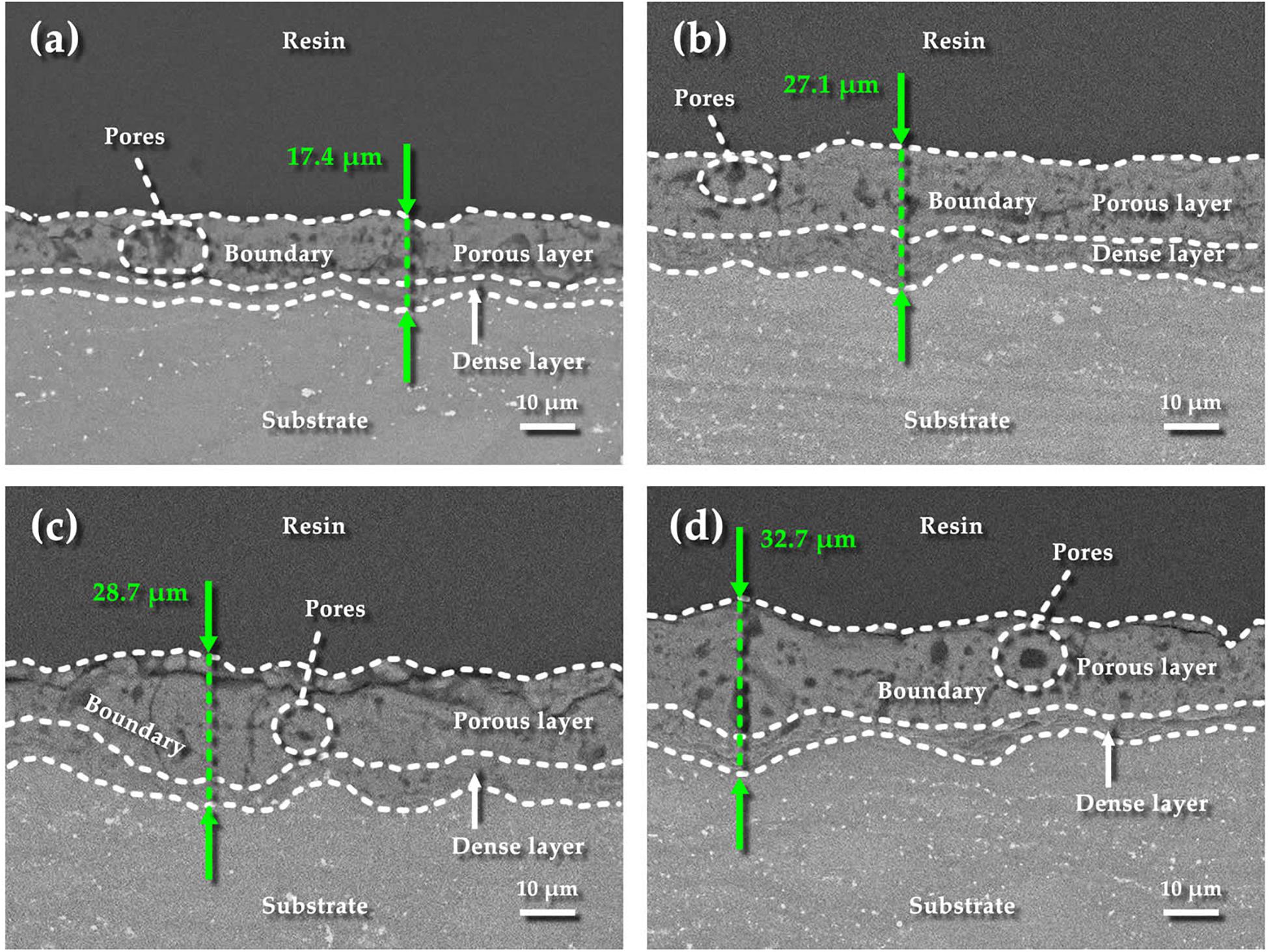
Figure 4. Cross-sectional morphologies of the coatings under different current modes: (a) 1.2 A; (b) 1.2–0.6 A; (c) 1.2–0.8 A; (d) 1.2–1.0 A.
Roughness of MAO Coatings Under Different Current Modes
Line roughness is evenly measured five times by selected parameter Ra on the specimen surface (Figure 5a). Besides, the average linear roughness has been calculated and displayed in Figure 5b. The average Ra value of MAO coating under 1.2–0.6 A mode is 1.8604 μm, which is lower than that under the other three modes. Under the constant current mode, the surface roughness of the MAO coating is 2.9770 μm, which is the highest Ra value in this work. It can be seen from Figure 3 that the coating fabricated under 1.2–0.6 mode is evenly distributed with small pores with size of 2–3 μm, and there are few microcracks. The coating porosity is 5.72, which is lower than that of 1.2–0.8 A and 1.2–1.0 A modes. It can also be seen from the cross-sectional morphology that the coating surface is uniform under 1.2–0.6 A mode (Figure 4b). However, the coating fabricated under 1.2 A mode has the lowest porosity but continuous coarse cracks. This morphology may be caused by the excessive energy in the last stage under the constant current mode, and the insufficient cooling of the surrounding electrolyte.
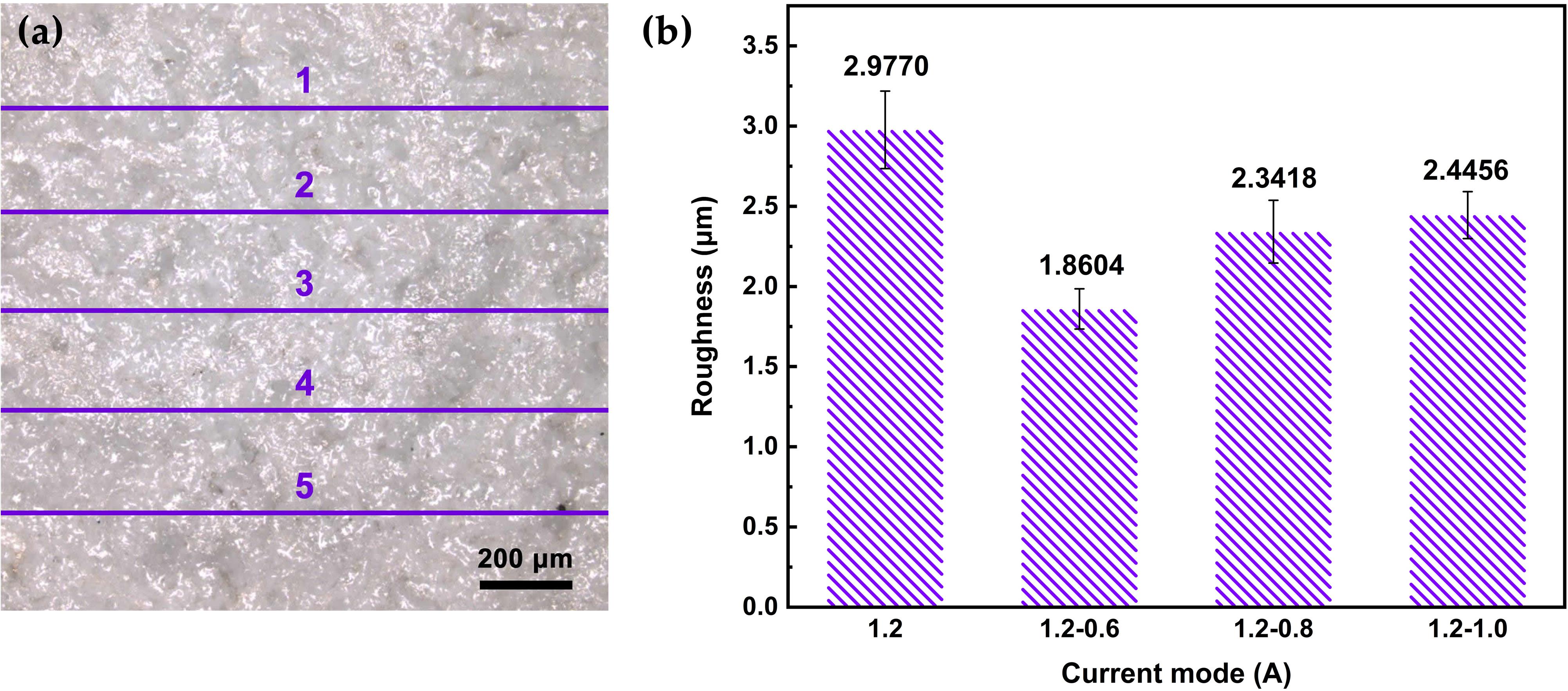
Figure 5. (a) Schematic image of MAO coating roughness measured by five lines; (b) roughness of MAO coatings under different current modes.
Thickness and Microhardness of MAO Coatings Under Different Current Modes
Figure 6 shows the average thickness and microhardness of the coated specimens fabricated by different current modes. The coating becomes thicker under two-steps current-decreasing mode. In order to more intuitively indicate the inconsistencies of the change in the coating thickness, we show the square of the error bar, that is, the variance in Figure 6A. While the variance of coating thickness is lower, indicating a better uniformity of the coating. At the final stage (300–900 s) of MAO process, the high current in the 1.2 A mode leads to some large splitting point discharge sparks on the surface of the specimen, which causes the cracking and spalling of the MAO coatings. However, the lower current in the final stage can effectively avoid the severe discharging under two-steps current-decreasing mode and hence the coatings are thicker and more uniform.
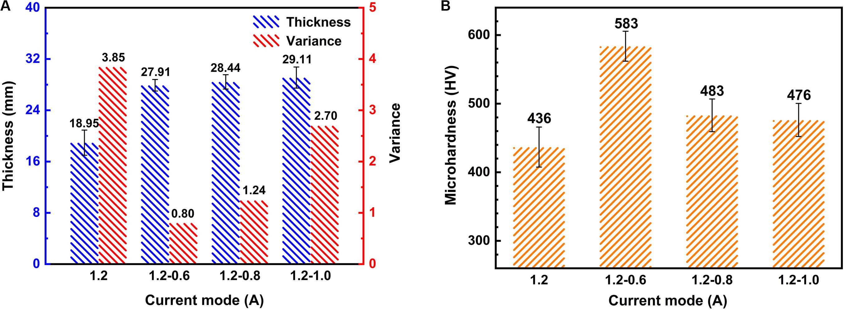
Figure 6. (A) Coating thickness, variance, and (B) corrosion rate under different current modes.
To further investigate the properties of the coatings, the microhardness was measured as shown in Figure 6B. Obviously, the values of microhardness of coatings fabricated under two steps current-decreasing mode are higher than that fabricated under constant current mode. The 1.2–0.6 A mode shows the highest microhardness with a value of 583 HV, which is 34% higher than the lowest value of 436 HV in the 1.2 A mode. It has been reported that the thickness and compactness of the coating determine the performance of the coating (Lu et al., 2011). It can be confirmed by Figures 3, 4 that the coating fabricated under 1.2–0.6 A mode is uniform and dense, therefore, the hardness is high. The coating fabricated under the constant current mode has the lowest thickness and a large number of defects such as pores and microcracks, so the hardness is the lowest. Although the thickness of the coating fabricated under the other two modes is higher than that of the coating fabricated under 1.2–0.6 A mode, it also has a lot of flaws, which is not conducive to the improvement of the hardness. Hence it is easy to understand that the coatings fabricated under two-steps current-decreasing mode have a higher microhardness due to the compact coating.
Nanoscratch Tests of MAO Coatings
Figure 7 illustrates the relationship between penetration depth/acoustic emission and normal force/displacement of MAO specimens under different current modes. In the figure, PD stands for the penetration depth curve and AE means acoustic emission curve. Lc stands for loading force when the coatings are scratched. The images below the curves show the corresponding scratch tracks. The peaks of the acoustic emission curve are associated with the detection of flaws in MAO coatings (Chen et al., 2018a).
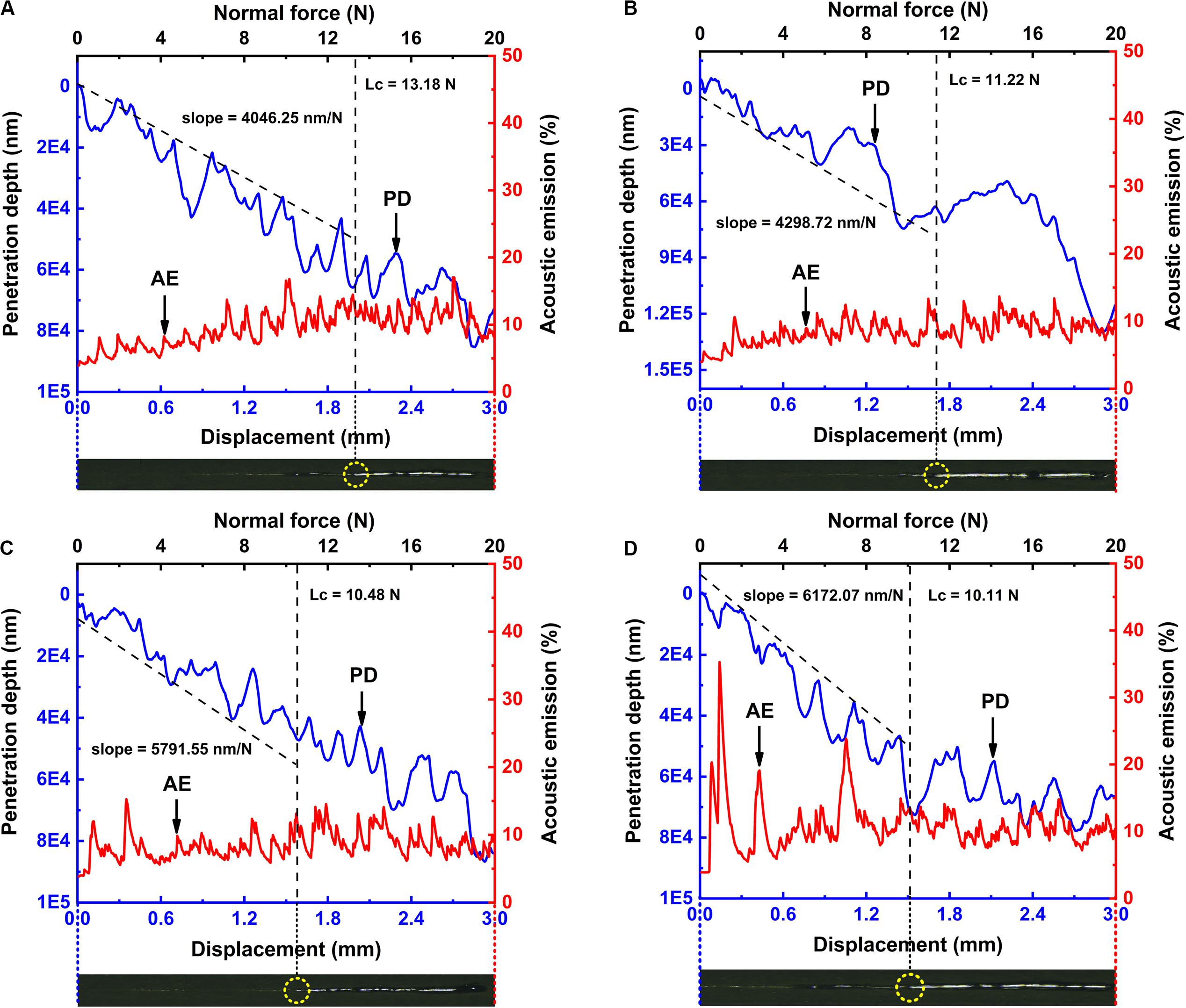
Figure 7. Penetration depth and acoustic emission as a function of scratch load and displacement of MAO coatings under different current modes for (A) 1.2–0.6 A, (B) 1.2–0.8 A, (C) 1.2–1.0 A, and (D) 1.2 A. The images below each curve are the corresponding scratch tracks. The slopes of the penetration depth curves are 4046.25 nm/N for 1.2–0.6 A mode, 4298.72 nm/N for 1.2–0.8 A mode, 5791.55 nm/N for 1.2–1.0 A mode and 6172.07 nm/N for 1.2 A mode, indicating that MAO coating fabricated under 1.2–0.6 A mode is harder than those fabricated under the other three modes. The value of Lc under 1.2–0.6 A mode is 13.18 N, under 1.2–0.8 A mode is 11.22 N, under 1.2–1.0 A mode is 10.48 N and under 1.2 A mode is 11.95 N, indicating that MAO coating fabricated under 1.2–0.6 A mode has the best adhesion with the substrate.
Because of the many uneven ceramic phases and flaws distributed in MAO coatings, the acoustic signals were not stable. Nevertheless, when compared with the other figures, it can be found that in the MAO coating fabricated under the constant current mode (Figure 7D), the acoustic signal was more chaotic, indicating that there was much more coating peeling during the tests. The value of Lc under 1.2–0.6 A current mode is 13.18 N, which is larger than the other three modes, indicating the best adhesion between MAO coating and the substrate.
Since the penetration depth curves always consist of several segments (such as a MAO coating segment and a substrate segment), the slopes of the penetration depth curves are evaluated by linear fitting to approach the curves within the MAO coating segment. The lower the slope of the penetration depth curve, the more difficult it becomes for the indenter to penetrate MAO coatings. As seen from Figures 7A,D, the slopes of the penetration depth curves are 4046.25 nm/N for 1.2–0.6 A mode and 6172.07 nm/N for 1.2 A mode, indicating that the MAO coating fabricated under two-steps current-decreasing mode is harder than that fabricated under the constant current mode. These data are consistent with the above-mentioned coating hardness analysis, that is, the thickness and compactness are the key factors that determine the performance of the coating.
Corrosion Rates of MAO Coatings
Figure 8 shows the corrosion rate of the coated specimens fabricated by different current modes. The lower corrosion rate specifies and exhibits an improvement in corrosion resistance of the coatings prepared under two-steps current-decreasing mode. As can be seen from Figure 8, The corrosion rate of MAO coatings under two steps current-decreasing mode was significantly lower than that in constant current mode. It can be seen from the cross-sectional morphology (Figure 4) that the dense layer of the coating prepared under the constant current mode has the smallest thickness, and there are a large number of cracks and through pores in the porous layer. The presence of these defects cannot prevent the penetration of the corrosive medium, which is not conducive to the improvement of corrosion resistance. The thickness of the dense layer in the coating fabricated under the two-steps current-decreasing mode is larger than that in the coating fabricated under constant current mode. Under 1.2–0.6 A mode and 1.2–0.8 A mode, the dense layer has a larger thickness, and the porous layer has no obvious defects, hence the corrosion resistance is better. This morphology shows that the coating fabricated under the two steps current-decreasing mode is more compact, which can effectively prevent the penetration of corrosive medium (Wang et al., 2013; Li et al., 2019). Consequently, the coating fabricated under two steps current-decreasing mode exhibits a better corrosion resistance with a lower corrosion rate (such as 1.2–0.6).
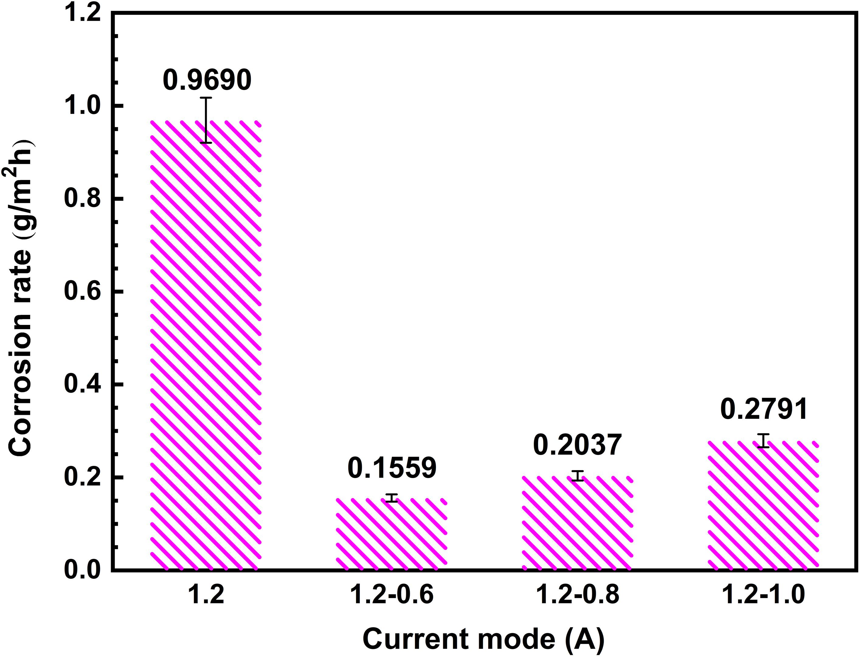
Figure 8. Corrosion rate of MAO coatings under different current modes.
Electrochemical Measurements
To better understand the corrosion behavior of MAO coatings under different current modes, the corrosion resistance of coatings is evaluated by electrochemical impedance spectroscopy (EIS) tests and potentiodynamic polarization performed in a 3.5 wt.% NaCl solution, as shown in Figure 9. It can be found in Figure 9A that the Nyquist plots of MAO coatings have different radii of capacitive loops which is related to the charge transfer process. Generally, the capacitive loop has a bigger radius, indicating greater charge transfer resistance and better corrosion resistance of the coatings (Dai et al., 2017; Lei et al., 2018; Sang et al., 2019; Zhang et al., 2019; Xiang et al., 2020). It can also be obviously found that the coatings fabricated under steps current-decreasing mode show greater radii of the capacitive loop compared with that under the constant current mode. As analyzed in the previous section, with the gradual decrease in the current in the final stage of the two-step current-decreasing mode, the resultant MAO coating is characterized with fewer defects and better uniformity. It would be of superior ability to protect the substrate from corrosion. Therefore, it would also exhibit a bigger capacitive loop during EIS test. Figure 9B shows the polarization curves of the coatings fabricated under different current modes. It can be seen that there are obvious differences in the polarization curves of MAO specimens under different modes. With the decrease of current, the corrosion current of specimens corresponding to each mode gradually decreases and the corrosion voltage gradually increases. To further confirm that truth, the fitting result for the corrosion potential and corrosion current are listed in Table 5. As it can be obviously observed that the coatings fabricated under steps current-decreasing mode show a more noble corrosion penitential and a lower current density, indicating the MAO coating under steps current-decreasing mode show a significant improvement in the protectiveness for the Mg substrate.
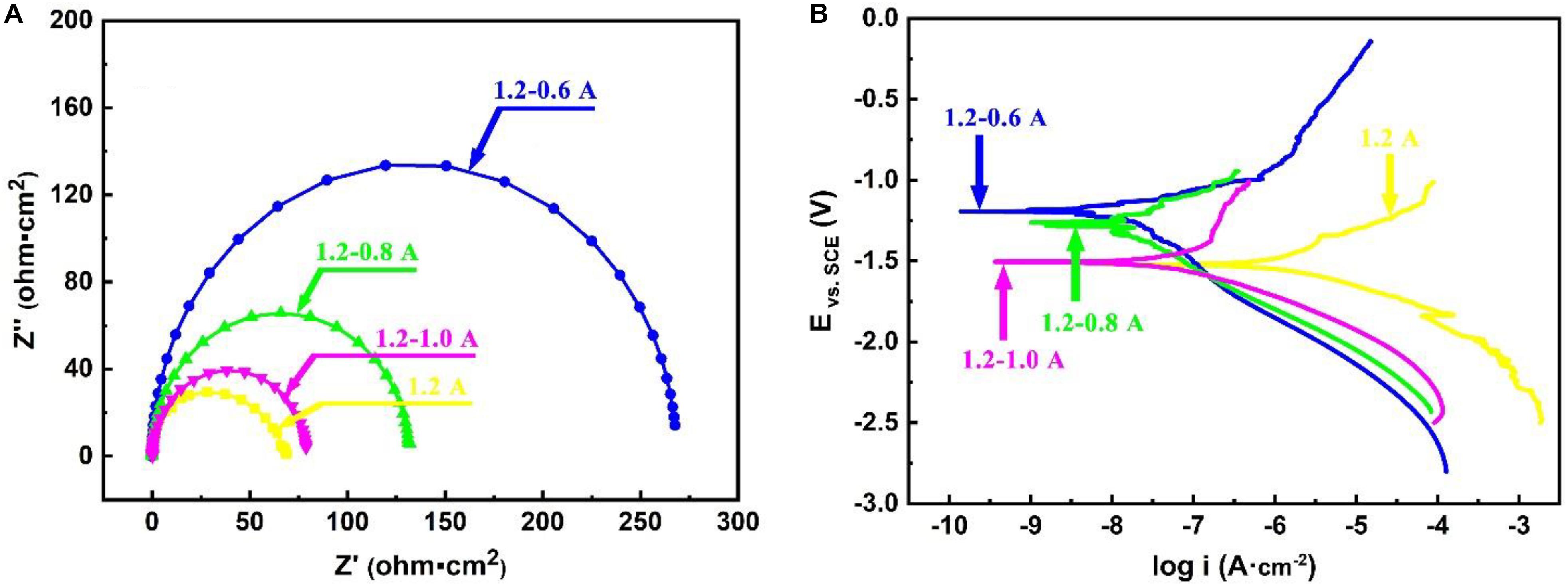
Figure 9. Electrochemical test results of MAO in 3.5 wt.% NaCl solution: (A) Nyquist; (B) polarization curves.
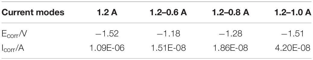
Table 5. Electrochemical parameters from polarization curves.
The impedance, corrosion potential, and current density are greatly influenced by the compactness and thickness of the protective layer (Bai et al., 2017; Liang et al., 2018; Qin et al., 2019; Yang et al., 2019). Therefore, the corrosion resistance of the coatings fabricated under steps current-decreasing mode better perform than that fabricated under the constant current mode, the steps current-decreasing mode can significantly enhance the properties of MAO coatings.
Conclusion
In this work, micro-arc oxidation (MAO) was performed on ZK60 under different power modes, the difference between the coatings in the constant current mode and two-step current-decreasing mode was compared and analyzed. After the examinations of microstructures, phase constituents, nanoscratch tests and electrochemical measurements, some key points can be concluded as follows.
(1) Under the constant current mode, due to the higher energy input, it leads to a severe discharging during the final stage of the MAO process. Therefore, a thinner coating was fabricated with some flaws, thereby having poorer corrosion resistance.
(2) The coatings fabricated under steps current-decreasing mode exhibit higher coating thickness, superior compactness and uniformity due to the lower input energy during the final stages of the MAO process. The steps current-decreasing mode has a profound effect on enhancing the corrosion resistance and microhardness of MAO coatings. The coatings fabricated under 1.2–0.6 A present the best performance.
(3) Comparing with the other MAO coatings under another three current modes. The coatings fabricated under 1.2–0.6 A two-steps current-decreasing mode shows the best corrosion resistance, the highest adhesion, the lowest roughness and the highest microhardness.
(4) Comparing with constant current mode, the steps current-decreasing mode can not only enhance the properties of MAO coatings but also can achieve great success in saving energy and reducing consumption.
Data Availability Statement
The raw data supporting the conclusions of this article will be made available by the authors, without undue reservation, to any qualified researcher.
Author Contributions
Z-XW, LS, and X-ZJ conceived and designed the experiments. J-WZ, FY, and W-GL performed the experiments. Z-XW, J-WZ, and SL analyzed the data. Z-XW and J-WZ wrote the manuscript. All authors contributed to the article and approved the submitted version.
Funding
This research was funded by the Postgraduate Research & Practice Innovation Program of Jiangsu Province (KYCX18_2317).
Conflict of Interest
W-GL was employed by the company Zhenjang Naisi Advanced Materials Co., Ltd.
The remaining authors declare that the research was conducted in the absence of any commercial or financial relationships that could be construed as a potential conflict of interest.
Acknowledgments
We would like to acknowledge the Instrumental Analysis Center of Jiangsu University of Science and Technology for providing technology support.
References
Bai, Y., Gai, X., Li, S. J., Zhang, L. C., Liu, Y. J., Hao, Y. L., et al. (2017). Improved corrosion behaviour of electron beam melted Ti-6Al-4V alloy in phosphate buffered saline. Corros. Sci. 123, 289–296. doi: 10.1016/j.corsci.2017.05.003
Barati Darband, G., Aliofkhazraei, M., Hamghalam, P., and Valizade, N. (2017). Plasma electrolytic oxidation of magnesium and its alloys: mechanism, properties and applications. J. Magnes. Alloys 5, 74–132. doi: 10.1016/j.jma.2017.02.004
Cai, Z., Lu, D., Li, W., Liang, Y., and Zhou, H. (2009). Study on anodic oxidation of magnesium in 6 M KOH solution by alternative current impedance. Int. J. Hydrog. Energy 34, 467–472. doi: 10.1016/j.ijhydene.2008.09.087
Chai, L. J., Chen, K., Zhi, Y., Murty, K. L., Chen, L. Y., and Yang, Z. N. (2018). Nanotwins induced by pulsed laser and their hardening effect in a Zr alloy. J. Alloys Compd. 748, 163–170. doi: 10.1016/j.jallcom.2018.03.126
Chen, H. B., Liu, T. M., Zhang, Y., Song, B., Hou, D. W., and Pan, F. S. (2016). The yield asymmetry and precipitation behavior of pre-twinned ZK60 alloy. Mater. Sci. Eng. A 652, 167–174. doi: 10.1016/j.msea.2015.11.092
Chen, L. Y., Li, J. X., Zhang, Y., Lu, W. J., Zhang, L. C., Wang, L. Q., et al. (2016). Effect of low-temperature pre-deformation on precipitation behavior and microstructure of a Zr-Sn-Nb-Fe-Cu-O alloy during fabrication. J. Nucl. Sci. Technol. 53, 496–507. doi: 10.1080/00223131.2015.1059776
Chen, J., Wang, Z. X., and Lu, S. (2012). Effects of electric parameters on microstructure and properties of MAO coating fabricated on ZK60 Mg alloy in dual electrolyte. Rare Met. 31, 172–177. doi: 10.1007/s12598-012-0486-7
Chen, L. Y., Shen, P., Zhang, L. N., Lu, S., Chai, L. J., Yang, Z. N., et al. (2018a). Corrosion behavior of non-equilibrium Zr-Sn-Nb-Fe-Cu-O alloys in high-temperature 0.01 M LiOH aqueous solution and degradation of the surface oxide films. Corros. Sci. 136, 221–230. doi: 10.1016/j.corsci.2018.03.012
Chen, L. Y., Xu, T. X., Lu, S., Wang, Z. X., Chen, S. J., and Zhang, L. C. (2018b). Improved hardness and wear resistance of plasma sprayed nanostructured NiCrBSi coating via short-time heat treatment. Surf. Coat. Technol. 350, 436–444. doi: 10.1016/j.surfcoat.2018.07.037
Chen, L. Y., Wang, H. Y., Zhao, C. H., Lu, S., Wang, Z. X., Sha, J., et al. (2019a). Automatic remelting and enhanced mechanical performance of a plasma sprayed NiCrBSi coating. Surf. Coat. Technol. 369, 31–43. doi: 10.1016/j.surfcoat.2019.04.052
Chen, L. Y., Xu, T. X., Wang, H. Y., Sang, P., Lu, S., Wang, Z. X., et al. (2019b). Phase interaction induced texture in a plasma sprayed-remelted NiCrBSi coating during solidification: an electron backscatter diffraction study. Surf. Coat. Technol. 358, 467–480. doi: 10.1016/j.surfcoat.2018.11.019
Chen, W. W., Wang, Z. X., Sun, L., and Lu, S. (2015). Research of growth mechanism of ceramic coatings fabricated by micro-arc oxidation on magnesium alloys at high current mode. J. Magnes. Alloys 3, 253–257. doi: 10.1016/j.jma.2015.07.003
Chen, X. M., Luo, C. P., and Liu, J. W. (2010). Study on the formation mechanism of micro-arc oxidation coatings on magnesium alloys. Mater. Sci. Forum 650, 228–233.
Dai, N. W., Zhang, J. X., Chen, Y., and Zhang, L. C. (2017). Heat treatment degrading the corrosion resistance of selective laser melted Ti-6Al-4V alloy. J. Electrochem. Soc. 164, C428–C434. doi: 10.1149/2.1481707jes
Dehnavi, V., Luan, B. L., Liu, X. Y., Shoesmith, D. W., and Rohani, S. (2015). Correlation between plasma electrolytic oxidation treatment stages and coating microstructure on aluminum under unipolar pulsed DC mode. Surf. Coat. Technol. 269, 91–99. doi: 10.1016/j.surfcoat.2014.11.007
Durdu, S., Bayramoğlu, S., Demirtaş, A., Usta, M., and Üçışık, A. H. (2013). Characterization of AZ31 Mg Alloy coated by plasma electrolytic oxidation. Vacuum 88, 130–133. doi: 10.1016/j.vacuum.2012.01.009
Ezhilselvi, V., Nithin, J., Balaraju, J. N., and Subramanian, S. (2016). The influence of current density on the morphology and corrosion properties of MAO coatings on AZ31B magnesium alloy. Surf. Coat. Technol. 288, 221–229. doi: 10.1016/j.surfcoat.2016.01.040
Forero López, A. D., Lehr, I. L., Brugnoni, L. I., and Saidman, S. B. (2018). Improvement in the corrosion protection and bactericidal properties of AZ91D magnesium alloy coated with a microstructured polypyrrole film. J. Magnes. Alloys 6, 15–22. doi: 10.1016/j.jma.2017.12.005
Goli, E., and Aghajani, H. (2018). A study on corrosion resistance of Al magnetron sputtering coated AZ31 magnesium alloy. Vacuum 152, 231–238. doi: 10.1016/j.vacuum.2018.03.032
Guo, H. X., An, M. Z., Huo, H. B., Xu, S., and Wu, L. N. (2006). Microstructure characteristic of ceramic coatings fabricated on magnesium alloys by micro-arc oxidation in alkaline silicate solutions. Appl. Surf. Sci. 252, 7911–7916. doi: 10.1016/j.apsusc.2005.09.067
Jiang, Y. L., Yu, Z. X., Xia, Q. X., Zhang, Y. J., Jiang, Z. H., Yao, Z. P., et al. (2013). Structure and corrosion resistance of PEO ceramic coatings on AZ91D mg alloy under three kinds of power modes. Int. J. Appl. Ceram. Technol. 10, E310–E317. doi: 10.1111/j.1744-7402.2012.02833.x
Jin, W. H., Wu, G. S., Feng, H. Q., Wang, W. H., Zhang, X. M., and Chu, P. K. (2015). Improvement of corrosion resistance and biocompatibility of rare-earth WE43 magnesium alloy by neodymium self-ion implantation. Corros. Sci. 94, 142–155. doi: 10.1016/j.corsci.2015.01.049
Krysmann, W., Kurze, P., Dittrich, K. H., and Schneider, H. G. (1984). Process characteristics and parameters of anodic oxidation by spark discharge (ANOF). Cryst. Res. Technol. 19, 973–979.
Kuang, J., Ba, Z. X., Li, Z. Z., Wang, Z. Z., and Qiu, J. H. (2020). The study on corrosion resistance of superhydrophobic coatings on magnesium. Appl. Surf. Sci. 501:144137. doi: 10.1016/j.apsusc.2019.144137
Lee, J. L., Jian, S. Y., Kuo, K. N., You, J. L., and Lai, Y. T. (2019). Effect of surface properties on corrosion resistance of ZK60 mg alloy microarc oxidation coating. IEEE Trans. Plasma Sci. 47, 1172–1180. doi: 10.1109/tps.2018.2868838
Lei, J. B., Shi, C., Zhou, S. F., Gu, Z. J., and Zhang, L. C. (2018). Enhanced corrosion and wear resistance properties of carbon fiber reinforced Ni-based composite coating by laser cladding. Surf. Coat. Technol. 334, 274–285. doi: 10.1016/j.surfcoat.2017.11.051
Li, C. Y., Feng, X. L., Fan, X. L., Yu, X. T., Yin, Z. Z., Bobby Kannan, M., et al. (2019). Corrosion and wear resistance of micro-arc oxidation composite coatings on magnesium alloy AZ31—the influence of inclusions of carbon spheres. Adv. Eng. Mater. 21:1900446. doi: 10.1002/adem.201900446
Liang, S. X., Jia, Z., Liu, Y. J., Zhang, W. C., Wang, W. M., Lu, J., et al. (2018). Compelling rejuvenated catalytic performance in metallic glasses. Adv. Mater. 30:1802764. doi: 10.1002/adma.201802764
Lin, X., Tan, L. L., Zhang, Q., Yang, K., Hu, Z. Q., Qiu, J. H., et al. (2013). The in vitro degradation process and biocompatibility of a ZK60 magnesium alloy with a forsterite-containing micro-arc oxidation coating. Acta Biomater. 9, 8631–8642. doi: 10.1016/j.actbio.2012.12.016
Lu, S., Wang, Z. X., Chen, J., and Zhou, X. S. (2011). Optimization of dual electrolyte and characteristic of micro-arc oxidation coating fabricated on ZK60 Mg alloy. Trans. Nonferrous Met. Soc. China 21, 929–935. doi: 10.1016/s1003-6326(11)60803-0
Lv, G. H., Chen, H., Gu, W. C., Li, L., Niu, E. W., Zhang, X. H., et al. (2008). Effects of current frequency on the structural characteristics and corrosion property of ceramic coatings formed on magnesium alloy by PEO technology. J. Mater. Process. Technol. 208, 9–13. doi: 10.1016/j.jmatprotec.2007.12.125
Ly, X. N., and Yang, S. (2019). Influence of current mode on microstructure and corrosion behavior of micro-arc oxidation (MAO) biodegradable Mg-Zn-Ca alloy in Hank’s solution. Surf. Coat. Technol. 358, 331–339. doi: 10.1016/j.surfcoat.2018.11.040
Niu, B., Shi, P., Shanshan, E., Wei, D. H., Li, Q., and Chen, Y. (2016). Preparation and characterization of HA sol-gel coating on MAO coated AZ31 alloy. Surf. Coat. Technol. 286, 42–48. doi: 10.1016/j.surfcoat.2015.11.056
Pan, H. C., Kang, R., Li, J. R., Xie, H. B., Zeng, Z. R., Huang, Q. Y., et al. (2020). Mechanistic investigation of a low-alloy Mg-Ca-based extrusion alloy with high strength-ductility synergy. Acta Mater. 186, 278–290. doi: 10.1016/j.actamat.2020.01.017
Pan, H. C., Qin, G. W., Huang, Y. M., Ren, Y. P., Sha, X. C., Han, X. D., et al. (2018). Development of low-alloyed and rare-earth-free magnesium alloys having ultra-high strength. Acta Mater. 149, 350–363. doi: 10.1016/j.actamat.2018.03.002
Pan, H. C., Yang, C. L., Yang, Y. T., Dai, Y. Q., Zhou, D. S., Chai, L. J., et al. (2019). Ultra-fine grain size and exceptionally high strength in dilute Mg-Ca alloys achieved by conventional one-step extrusion. Mater. Lett. 237, 65–68. doi: 10.1016/j.matlet.2018.11.080
Patcas, F., and Krysmann, W. (2007). Efficient catalysts with controlled porous structure obtained by anodic oxidation under spark-discharge. Appl. Catal. A 316, 240–249. doi: 10.1016/j.apcata.2006.09.028
Peng, S. H., Li, M. Q., Wang, J. Y., Tian, Q. W., Wang, S. G., and Tang, B. (2019). Corrosion behavior and biological activity of micro-arc oxidation coating with puerarin on pure magnesium surface. Results Phys. 12, 1481–1489. doi: 10.1016/j.rinp.2019.01.021
Qin, P., Chen, Y., Liu, Y. J., Zhang, J. X., Chen, L. Y., Li, Y. H., et al. (2019). Resemblance in corrosion behavior of selective laser melted and traditional monolithic β Ti-24Nb-4Zr-8Sn alloy. ACS Biomater. Sci. Eng. 5, 1141–1149. doi: 10.1021/acsbiomaterials.8b01341
Rabadia, C. D., Liu, Y. J., Zhao, C. H., Wang, J. C., Jawed, S. F., Wang, L. Q., et al. (2019). Improved trade-off between strength and plasticity in titanium based metastable beta type Ti-Zr-Fe-Sn alloys. Mater. Sci. Eng. A 766, 138340. doi: 10.1016/j.msea.2019.138340
Ramalingam, V. V., Ramasamy, P., Kovukkal, M. D., and Myilsamy, G. (2019). Research and development in magnesium alloys for industrial and biomedical applications: a review. Met. Mater. Int. 26, 409–430. doi: 10.1007/s12540-019-00346-8
Ren, Y. F., Babaie, E., and Bhaduri, S. B. (2018). Nanostructured amorphous magnesium phosphate/poly (lactic acid) composite coating for enhanced corrosion resistance and bioactivity of biodegradable AZ31 magnesium alloy. Prog. Org. Coat. 118, 1–8. doi: 10.1016/j.porgcoat.2018.01.014
Sang, P., Chen, L. Y., Zhao, C. H., Wang, Z. X., Wang, H. Y., Lu, S., et al. (2019). Particle size-dependent microstructure, hardness and electrochemical corrosion behavior of atmospheric plasma sprayed NiCrBSi coatings. Metals 9:1342. doi: 10.3390/met9121342
Santos, E., de Souza, G. B., Serbena, F. C., Santos, H. L., de Lima, G. G., Szesz, E. M., et al. (2017). Effect of anodizing time on the mechanical properties of porous titania coatings formed by micro-arc oxidation. Surf. Coat. Technol. 309, 203–211. doi: 10.1016/j.surfcoat.2016.11.063
Shao, Z. C., Zhang, F. F., Cai, Z. Q., and Hu, R. (2017). Process and performance of electroless nickel plating on AZ91D magnesium alloy. Anti Corros. Methods Mater. 64, 162–169. doi: 10.1108/acmm-03-2015-1513
Sobrinho, P. H., Savguira, Y., Ni, Q., and Thorpe, S. J. (2017). Statistical analysis of the voltage-time response produced during PEO coating of AZ31B magnesium alloy. Surf. Coat. Technol. 315, 530–545. doi: 10.1016/j.surfcoat.2017.02.029
Song, B., Xin, R. L., Sun, L. Y., Chen, G., and Liu, Q. (2013). Enhancing the strength of rolled ZK60 alloys via the combined use of twinning deformation and aging treatment. Mater. Sci. Eng. A 582, 68–75. doi: 10.1016/j.msea.2013.06.047
Sun, J. Y., Cai, S., Wei, J. L., Shen, K. E., Ling, R., Sun, J. E., et al. (2020). Long-term corrosion resistance and fast mineralization behavior of micro-nano hydroxyapatite coated magnesium alloy in vitro. Ceram. Int. 46, 824–832. doi: 10.1016/j.ceramint.2019.09.038
Venkatraman, S. K., and Swamiappan, S. (2020). Review on calcium- and magnesium-based silicates for bone tissue engineering applications. J. Biomed. Mater. Res. Part A 108, 1546–1562. doi: 10.1002/jbm.a.36925
Wang, H. Y., Li, Q. M., and Gao, C. Z. (2014). Preparation of nanometer nickel powder from spent electroless nickel plating baths by using thiourea dioxide as a green reductant. J. Clean. Prod. 84, 701–706. doi: 10.1016/j.jclepro.2014.03.091
Wang, L., Fu, W., and Chen, L. (2011). Evolution of active species and discharge sparks in Na2SiO3 electrolyte during PEO process. J. Alloys Compd. 509, 7652–7656. doi: 10.1016/j.jallcom.2011.04.130
Wang, Z. X., Chen, G. Q., Chen, L. Y., Xu, L., and Lu, S. (2018). Degradation behavior of micro-arc oxidized ZK60 magnesium alloy in a simulated body fluid. Metals 8:724. doi: 10.3390/met8090724
Wang, Z. X., Lv, W. G., Chen, J., and Lu, S. (2013). Characterization of ceramic coating on ZK60 magnesium alloy prepared in a dual electrolyte system by micro-arc oxidation. Rare Met. 32, 459–464. doi: 10.1007/s12598-013-0152-8
Wu, H. L., Cheng, Y. L., Li, L. L., Chen, Z. H., Wang, H. M., and Zhang, Z. (2007). The anodization of ZK60 magnesium alloy in alkaline solution containing silicate and the corrosion properties of the anodized films. Appl. Surf. Sci. 253, 9387–9394. doi: 10.1016/j.apsusc.2007.05.085
Xiang, K., Chen, L. Y., Chai, L. J., Guo, N., and Wang, H. (2020). Microstructural characteristics and properties of CoCrFeNiNbx high-entropy alloy coatings on pure titanium substrate by pulsed laser cladding. Appl. Surf. Sci. 517:146214. doi: 10.1016/j.apsusc.2020.146214
Xin, S. G., Song, L. X., Zhao, R. G., and Hu, X. F. (2006). Composition and thermal properties of the coating containing mullite and alumina. Mater. Chem. Phys. 97, 132–136. doi: 10.1016/j.matchemphys.2005.07.073
Yahalom, J., and Zahavi, J. (1970). Electrolytic breakdown crystallization of anodic oxide films on Al, Ta and Ti. Electrochim. Acta 15, 1429–1435. doi: 10.1016/0013-4686(70)80064-0
Yang, W., Xu, D. P., Wang, J. L., Yao, X. F., and Chen, J. (2018). Microstructure and corrosion resistance of micro arc oxidation plus electrostatic powder spraying composite coating on magnesium alloy. Corros. Sci. 136, 174–179. doi: 10.1016/j.corsci.2018.03.004
Yang, Z., Wang, R. Q., Liu, C., Wu, Y. K., Wang, D. D., Liu, X. T., et al. (2019). The electrochemical corrosion behavior of plasma electrolytic oxidation coatings fabricated on aluminum in silicate electrolyte. J. Mater. Eng. Perform. 28, 3652–3660. doi: 10.1007/s11665-019-04099-8
Yao, Z. P., Wang, D. L., Xia, Q. X., Zhang, Y. J., Jiang, Z. H., and Wang, F. P. (2013). Effect of PEO power modes on structure and corrosion resistance of ceramic coatings on AZ91D Mg alloy. Surf. Eng. 28, 96–101. doi: 10.1179/1743294411y.0000000045
Zang, Q. H., Chen, H. M., Lee, Y. S., Yu, H. S., Kim, M. S., and Kim, H. W. (2020). Improvement of anisotropic tensile properties of Al-7.9Zn-2.7Mg-2.0Cu alloy sheets by particle stimulated nucleation. J. Alloys Compd. 828, 154330. doi: 10.1016/j.jallcom.2020.154330
Zeng, Z. R., Stanford, N., Davies, C. H. J., Nie, J. F., and Birbilis, N. (2018). Magnesium extrusion alloys: a review of developments and prospects. Int. Mater. Rev. 64, 27–62. doi: 10.1080/09506608.2017.1421439
Zhang, J., Gu, Y. H., Guo, Y. J., and Ning, C. Y. (2012). Electrochemical behavior of biocompatible AZ31 magnesium alloy in simulated body fluid. J. Mater. Sci. 47, 5197–5204. doi: 10.1007/s10853-012-6403-5
Zhang, L. C., and Chen, L. Y. (2019). A review on biomedical titanium alloys: recent progress and prospect. Adv. Eng. Mater. 21:1801215. doi: 10.1002/adem.201801215
Zhang, L. C., Chen, L. Y., and Wang, L. Q. (2020). Surface modification of titanium and titanium alloys: technologies, developments, and future interests. Adv. Eng. Mater. 22:1901258. doi: 10.1002/adem.201901258
Zhang, L. C., Jia, Z., Lyu, F. C., Liang, S. X., and Lu, J. (2019). A review of catalytic performance of metallic glasses in wastewater treatment: recent progress and prospects. Prog. Mater Sci. 105:100576. doi: 10.1016/j.pmatsci.2019.100576
Zhang, L. C., and Xu, J. (2004). Glass-forming ability of melt-spun multicomponent (Ti, Zr, Hf)-(Cu, Ni, Co)-Al alloys with equiatomic substitution. J. Non⋅Cryst. Solids 347, 166–172. doi: 10.1016/j.jnoncrysol.2004.09.007
Zhang, L. C., Xu, J., and Eckert, J. (2006a). Thermal stability and crystallization kinetics of mechanically alloyed TiC/Ti-based metallic glass matrix composite. J. Appl. Phys. 100:033514. doi: 10.1063/1.2234535
Zhang, L. C., Xu, J., and Ma, E. (2006b). Consolidation and properties of ball-milled Ti50Cu18Ni22Al4Sn6 glassy alloy by equal channel angular extrusion. Mater. Sci. Eng. A 434, 280–288. doi: 10.1016/j.msea.2006.06.085
Zhu, Y. Y., Chang, W. H., Zhang, S. F., Song, Y. W., Huang, H. D., Zhao, R. F., et al. (2019). Investigation on corrosion resistance and formation mechanism of a P-F-Zr contained micro-arc oxidation coating on AZ31B magnesium alloy using an orthogonal method. Coatings 9:197. doi: 10.3390/coatings9030197
Keywords: properties, micro-arc oxidation, magnesium, two steps current-decreasing mode, dual electrolyte
Citation: Wang Z-X, Zhang J-W, Ye F, Lv W-G, Lu S, Sun L and Jiang X-Z (2020) Properties of Micro-Arc Oxidation Coating Fabricated on Magnesium Under Two Steps Current-Decreasing Mode. Front. Mater. 7:261. doi: 10.3389/fmats.2020.00261
Received: 03 June 2020; Accepted: 16 July 2020;
Published: 18 September 2020.
Edited by:
Linjiang Chai, Chongqing University of Technology, ChinaReviewed by:
Jun Cheng, Northwest Institute for Non-Ferrous Metal Research, ChinaBo Song, Southwest University, China
Copyright © 2020 Wang, Zhang, Ye, Lv, Lu, Sun and Jiang. This is an open-access article distributed under the terms of the Creative Commons Attribution License (CC BY). The use, distribution or reproduction in other forums is permitted, provided the original author(s) and the copyright owner(s) are credited and that the original publication in this journal is cited, in accordance with accepted academic practice. No use, distribution or reproduction is permitted which does not comply with these terms.
*Correspondence: Sheng Lu, lusheng_ktz@just.edu.cn