
Abstract
Motivated by the huge practical engineering demand for the fundamental understanding of mechanical characteristics of high-speed railway infrastructure, a full-scale multi-functional test platform for high-speed railway track–subgrade system is developed in this paper, and its main functions for investigating the mechanical performance of track–subgrade systems are elaborated with three typical experimental examples. Comprising the full-scale subgrade structure and all the five types of track structures adopted in Chinese high-speed railways, namely the CRTS I, the CRTS II and the CRTS III ballastless tracks, the double-block ballastless track and the ballasted track, the test platform is established strictly according to the construction standard of Chinese high-speed railways. Three kinds of effective loading methods are employed, including the real bogie loading, multi-point loading and the impact loading. Various types of sensors are adopted in different components of the five types of track–subgrade systems to measure the displacement, acceleration, pressure, structural strain and deformation, etc. Utilizing this test platform, both dynamic characteristics and long-term performance evolution of high-speed railway track–subgrade systems can be investigated, being able to satisfy the actual demand for large-scale operation of Chinese high-speed railways. As examples, three typical experimental studies are presented to elucidate the comprehensive functionalities of the full-scale multi-functional test platform for exploring the dynamic performance and its long-term evolution of ballastless track systems and for studying the long-term accumulative settlement of the ballasted track–subgrade system in high-speed railways. Some interesting phenomena and meaningful results are captured by the developed test platform, which provide a useful guidance for the scientific operation and maintenance of high-speed railway infrastructure.
1 Introduction
Since the operation of Beijing–Tianjin inter-city high-speed railway in 2008, Chinese high-speed railway has made a rapid development and remarkable achievement [1]. Until the end of 2019, the total operation mileage of Chinese high-speed railway has exceeded 35,000 km, which occupies more than two-thirds of the total operation mileage of the high-speed railway lines all over the world. In recent years, due to the long-time operation and the effect of the complicated environment conditions, some practical engineering problems of the high-speed track–subgrade system are gradually exposed, for instance, cracks of concrete slab, fatigue of fastener system and settlement of infrastructure, which have already compromised the running performance of high-speed trains and increased the maintenance cost [1]. In order to effectively ensure operation safety and provide a scientific reference for maintenance, the mechanical behavior and the deterioration process of the track–subgrade system should be well understood and deeply investigated.
After years of research, many useful methods have been proposed to explore the dynamic performance and the long-term performance of the track–subgrade system, which can be generally divided into three categories, including field test, laboratory test and numerical analysis. Obviously, field tests are the most reliable technique to achieve the target; however, it cannot be generalized due to the difficulty of laying sensors, the high cost of long-term tests, the potential threat to running trains and so on [2]. Numerical analysis is another efficient method to estimate the mechanical performance of the track–subgrade system, which has already been widely used in railway engineering [3,4,5]. Nevertheless, the accuracy and effectiveness of the established numerical models are difficult to validate, leading to questionable conclusions in some cases. In contrast, laboratory test is an alternative method to investigate the mechanical behaviors of the track–subgrade system, especially for high-speed railways where field experiments are more difficult to carry out.
Until now, numerous researchers have designed various test platforms for track structures and for track–subgrade systems and proposed valuable suggestions based on the established test rigs. Simulating the external excitations with the help of hydraulic jacks, Al Shaer et al. [6] designed a 1:3 reduced-scale test system as shown in Fig. 1a to investigate the dynamic behavior and the settlement of ballasted tracks. Two full-scale test platforms were constructed by Department of Railway Engineering and Track Management in University of Žilina (Fig. 1b) to explore the influence of climatic factors on track and subgrade structure, which were built according to the materials and dimensions in actual railway lines [7]. Considering two steel rails, 15 aluminum sleepers, model ballast and steel subgrade, Ishikawa et al. [8] established a 1:5 scale test model of ballasted track according to a normally adopted track structure in Japanese railway system. Adopting this platform, a single-point loading test and a moving loading test were conducted to study the cyclic deformation of granular material. Momoya et al. [9] also designed a 1:5 reduced-scale test platform for ballasted track to investigate the settlement of subgrade subject to a single-point load and a moving load. In addition, Borwn et al. [10] established a test rig with dimensions of 4.1 m × 2.1 m × 1.9 m based on the Nottingham railway line to determine the deformation of ballast under moving loads, in which hydraulic actuators were employed to simulate the loads acting on the sleeper. Considering three 2.5-m-long full-scale floating track slab, Cox et al. [11] established a test rig to measure the dynamic performance of floating slabs. Except the above large size test platforms, many box test devices were also designed and constructed to investigate the mechanical property of ballast [12,13,14].

Test platforms for track and subgrade structures in different research organizations: a University Paris-Est Marne-la-Vallée; b University of Žilina; c Zhejiang University; d Central South University
In China, with the rapid development of high-speed railways, some full-scale test platforms were established by different research organizations in recent years to explore the dynamic behavior of the track and subgrade structure. At Zhejiang University, a full-scale physical model for a ballastless track was built to investigate the dynamic performance of the slab track system in high-speed railways, as shown in Fig. 1c. This test rig, with dimensions 13.1 m × 5 m × 2.7 m (length × width × depth), consists of almost all the actual track components, including the rail, the fastener, the concrete slab, the cement–asphalt (CA) mortar layer, the concrete base and the subgrade. With the help of hydraulic actuators, single-point loading tests and moving loading tests can be performed [15, 16]. In Central South University, a large test platform with dimensions of 30 m × 13 m × 6 m was constructed to study the dynamic performance of the track–subgrade system subject to high axle loading and severe weather, as shown in Fig. 1d [17]. This platform includes both normal ballastless track–subgrade system section and track transition zone. Additionally, Southwest Jiaotong University (SWJTU), Tongji University and some other universities also established test platforms for high-speed track structures and track–subgrade systems to figure out the dynamic performance of this large mechanical system [18, 19].
With respect to the existing test platforms for track–subgrade system, some of them are focusing on only one type of track structure, some are reduced-scale models, and some only consider parts of the whole system. To comprehensively and effectively investigate the mechanical behaviors of all the five types of track structures widely used in Chinese high-speed railways, a full-scale multi-functional test platform for investigating mechanical performance of different track–subgrade systems, named HTST, is designed and constructed by the research team of Train and Track Research Institute (TTRI) at SWJTU, China. This article aims to give a comprehensive and systematical introduction to this platform for the first time. The background of this test platform is briefly introduced in Sect. 2, and the design and development processes are explained in Sect. 3 and Sect. 4. Then, the function and characteristic of the test platform are presented in Sect. 5. Section 6 demonstrates three typical experimental studies utilizing the established test platform. At the end of this paper, some remarkable conclusions are reached.
2 Development background of the test platform
In the last decade, Chinese high-speed railway has achieved a great progress. As time goes on, some serious problems in the track–subgrade system gradually emerge, such as cracks on concrete slabs and bases, fatigue of fastener systems, interface damage of slab tracks and settlement of the subgrade. To meet the huge practical engineering demand for guaranteeing the running safety of high-speed trains and for scientifically guiding the maintenance of infrastructure, it is extremely important to acquire the mechanical behaviors of track–subgrade structures in high-speed railways. Moreover, in view of multiple types of track structures adopted in Chinese high-speed railways, whose mechanical performances are different from each other, a complete full-scale multi-functional test platform considering multiple track structures is urgently needed.
Under the full support of the Ministry of Science and Technology of China, the former Ministry of Railways of China, the Ministry of Education of China and Sichuan Provincial Government, SWJTU decided to construct a comprehensive laboratory for fundamental research of high-speed railway, i.e., the Laboratory for Rail Transportation with a covered area of 44,200 m2. Taking advantage of this opportunity, the HTST test platform for high-speed track–subgrade systems was synchronously planned and finally established as an important component of the Laboratory for Rail Transportation. In 2005, the director of TTRI at SWJTU, also the first author of this article, proposed the design idea and the initial scheme of the full-scale multi-functional test platform for high-speed track–subgrade systems; subsequently, the HTST test platform started to be constructed in 2010, and it was finally completed in 2013.
3 Design scheme of the test platform
To develop a full-scale multi-functional test platform for different track–subgrade systems is an essential but challenging task in railway community; its complexity involves interdisciplinary and multidisciplinary work in track dynamics, soil dynamics, damage and fatigue mechanics, measurement and instrumentation technology, and experimental techniques, requiring some sophistication in the establishment process. Fortunately, the TTRI at SWJTU has focused on investigating dynamic behaviors of different railway systems for nearly 30 years, including high-speed railway, heavy haul railway and urban railway systems, having extensive research experiences and a vast amount of research achievements [5, 20,21,22,23,24,25].
On the basis of the previous studies, we formed the final design scheme of the test platform after numerous investigations and discussions. Here are listed the key points considered in the design:
-
Full-scale platform The dimensions of the test platform are 72.5 m × 6 m × 5.87 m (length × width × depth), whose cross sections are the same as those in the actual track–subgrade system of Chinese high-speed railways.
-
Complete track–subgrade system The test platform consists of rails, fasteners, detailed ballasted/ballastless track systems, the top layer of subgrades, the bottom layer of subgrades and embankments.
-
High-speed railway standard The design standard for different track–subgrade systems in the test platform is exactly the same as that for Chinese high-speed railways.
-
Actual construction material The materials of the established track–subgrade test platform are the same as the materials employed in actual high-speed railways in China.
-
Multiple track types All five types of track structures adopted in Chinese high-speed railways are considered, namely the CRTS I, the CRTS II and the CRTS III ballastless tracks, the double-block ballastless track and the ballasted track, whose detail parameters can be found in Ref. [26]. The cross sections of all the tracks are given in Fig. 2. It is worth mentioning that the entire test platform also contains the floating slab track structure adopted in metro system, which is not in the scope of this work.
Fig. 2 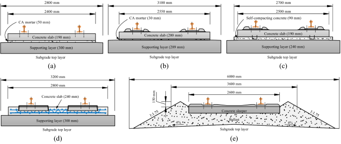
Cross sections of the track structures in the test platform: a CRTS I slab track; b CRTS II slab track; c CRTS III slab track; d double-block ballastless track; e ballasted track
-
Various loading methods Three kinds of loading methods are employed, including the real bogie loading, the multi-point loading and the impact loading. The first two loading methods are achieved with the help of hydraulic actuators and the designed loading frames, and the last loading method is implemented by a wheel-drop testing vehicle.
-
Extensive measurement indicators Three kinds of test contents are considered for the analysis of dynamic behavior and long-term performance of the track–subgrade system, i.e., structural vibration (SV), structural deformation (SD) and structural force (SF). The measurement indicators are listed in Table 1.
Table 1 Measurement indicators of the test platform

According to the above items, the general design of the test platform is displayed in Fig. 3. Taking the ballasted track section as an example, the layout scheme of the sensors in the subgrade is illustrated in detail in Fig. 4, and the sensor layouts in other track sections are similar.

Detailed design scheme of the test platform

Layout scheme of the sensors in subgrade at ballasted track section: a layout scheme; b front view; c side view
4 Establishment of the test platform
Based on the above design scheme, the test platform was developed strictly according to the construction standard in Chinese high-speed railways, which was completed in 2013. In this part, the construction process, sensor layout process and loading methods are technically presented.
4.1 Construction of the test platform
Figure 5 gives the flowchart of the construction process for the test platform of high-speed railway track–subgrade systems.

General construction process of the test platform
Taking the CRTS I slab track as an example, the construction process is illustrated in detail as follows. Primarily, the construction of the subgrade is displayed in Fig. 6, in which the thickness of the bottom layer of the subgrade is 2.3 m, while the thickness of the top layer of the subgrade is 0.4 m for the ballastless track and 0.7 m for the ballasted track, respectively. The compaction indices of the subgrade and embankment are listed in Table 2, where K is the compaction coefficient, K30 denotes the soil reaction coefficient and Evd represents the dynamic deformation modulus. The compaction coefficient K is the ratio of the dry density of the compacted soil to its maximum dry density obtained from the modified Proctor test. Static plate load tests using a circular plate with a diameter of 30 cm are used to obtain the stiffness parameters, such as the K30 value and Evd.

Construction of the subgrade in the platform: a earthwork excavation; b compaction
After the subgrade work was finished, a cast-in-place reinforced concrete base was built as illustrated in Fig. 7a. The concrete base has a dimension of 15.096 m × 2.8 m × 0.3 m (length × width × thickness) with the reinforcement laid on the top of the subgrade surface. On this basis, three prefabricated slabs are arranged above the base, as shown in Fig. 7b. Meanwhile, a device is applied to separate the concrete slab and the concrete base for grouting the CA mortar in between.

Construction of concrete base and slab for CRTS I slab track system: a arrangement of reinforcement; b layout of prefabricated slab
It should be underlined that the sensors and wirings embedded in the ground are carefully protected in the construction process of the subgrade and the track, which is described in detail in Sect. 4.2.
Following the above construction steps, the CN60 rails were installed on the slabs with fastener systems. The rail pad static stiffness is 20-30 kN/mm for the ballastless track and 50-70 kN/mm for the ballasted track. Then, the CA mortar was grouted as illustrated in Fig. 8. For the CRTS I slab track system, the CA mortar has two basic functions: (a) adjusting the height of rail installation and (b) providing a certain elasticity in the track system. After produced by using the mortar mill as shown in Fig. 8a, the mortar should be evaluated to ensure its mechanical performance (Fig. 8b). For CRTS I slab track, the elasticity modulus of the mortar should be 100-300 MPa. If the mortar was qualified, the grouting process was then executed with a fixture from the gaps between adjacent slab ends (shown in Fig. 8c) until the filled mortar was presently uniformed (Fig. 8d). Finally, the track construction for the CRTS I track was completed. The construction process for other track structures is similar, which can be referred to in “Code for Design of High Speed Railway (TB 10621-2014)” [27].

Mortar grouting process for the CRTS I slab track system: a mortar mill; b evaluation of milled mortar; c mortar grouting; d uniformly grouted mortar
After all the tracks were constructed, a measurement of the rail irregularity was conducted to ensure the precision of the track laying process. The measurement items are listed in Table 3. Finally, the entire track–subgrade system of the HTST test platform was established, as displayed in Fig. 9. It should be noted that the subgrade is sealed with plain concrete. Besides, in the construction process, the locations and fixtures for the loading frame were also established on the concrete side walls.

Constructed track–subgrade system for Chinese high-speed railways
4.2 Layout of the sensors
According to the design scheme of the test platform, the layout process of sensors embedded in the subgrade structure should be synchronized with the construction process of the platform.
Following the sensor layout scheme in Fig. 4, the sensors were embedded at different heights in the subgrade structure. Figure 10 shows the sensor layout process at a certain height. As can be seen, the sensors and their wirings are all protected.

Sensor layout process in subgrade: a sensor layout; b sensor wirings
-
(1)
Sensor protection. Small plastic boxes are designed and made to place the sensors, and the sensors are pasted to the bottom of the box to ensure that the vibrations of the boxes and sensors are consistent (Fig. 10a). Moreover, the boxes are laid inside the subgrade, leading to the removal of gravels or sands in the same location in the subgrade. To make the mass of the removed gravels or sands the same as that of the box and sensor, steel grits are filled in the box to adjust the mass.
-
(2)
Sensor wirings protection. PVC pipes are adopted to protect and trace the wirings. The wirings in the horizontal plane are all guided to the concrete side wall and then led out of the ground, as shown in Fig. 10b.
The instrumentation of the track structure is illustrated in Fig. 11 for the ballastless track and presented in Fig. 12 for the ballasted track. In the ballastless track, the pressure sensors and strain gauges are laid on the surface of the base to measure the pressure and the lateral and longitudinal strains of the base (Fig. 11a, b). After the sensors are installed, the construction of the slab and the CA mortar is then conducted. Additionally, sensors for measuring the rail and slab vibrations are mounted on the surface of each component, as shown in Figs. 11c, d.

Sensors layout process in ballastless track: a strain gauge on base surface; b sensor layout scheme on base surface; c sensors for track vibration; d sensors for rail deformation and vibration

Sensor layout process in ballasted track: a device for measuring subgrade displacement; b displacement sensor of sleeper
For the sensors layout in the ballasted track, the measurement of track vibrations is relatively easy, compared with the measurement of subgrade displacements. To obtain the subgrade displacements at different heights, PVC pipes and steel bars are firstly inserted into the subgrade, and then, the displacements of steel bars are measured, which can represent the subgrade displacements because the bottoms of the steel bars are fixed to the underneath subgrade.
Table 4 lists basic technical parameters of the sensors adopted in this established test platform. Note that two kinds of pressure sensors are adopted in the subgrade for measuring different pressure levels. According to the design scheme in Fig. 5, the pressure sensors are laid totally in six different layers in the subgrade, including the top layer and the bottom layer. The sensors with the measurement range of 0.2 MPa are only used in the topside layer, while sensors with the measurement range of 0.1 MPa are employed in the other layers.
4.3 Loading methods
To effectively simulate the loads acting on the track–subgrade system, three kinds of loading methods are adopted in this established full-scale multi-functional test platform, namely the real bogie loading, the multi-point loading by a designed bogie frame and the impact loading by a wheel-drop testing vehicle, as displayed in Fig. 13.

Loading method used in the test platform: a real bogie loading; b multi-point loading; c impact loading
The real bogie loading and the multiple-point loading can be implemented through a designed loading frame (Fig. 13a, b), where hydraulic actuators are equipped. The steel loading frame is fixed on the concrete walls with large bolts, and the frame can be moved to different track sections with a gantry crane. The hydraulic actuators can act on the track structures directly or on the designed loading frames and bogies.
Another kind of loading method, the impact loading, can be implemented with the wheel-drop testing vehicle, as shown in Fig. 13c. The loading and running part has two running wheelsets installed under the chassis frame, which allows the testing car to move along the track. The supporting and moving part, an electric pushrod mechanism connected to the dropping wheelset (its weight is 1020 kg), is used to adjust the position of the dropping wheelset and make it automatically centered above the slab track system. The lifting part has an electromagnet to attract the dropping wheelset for changing the dropping height. The electromagnet is lifted by a windlass through a crown block and a hoist rope with a dynamometer, which can only move up and down along a slide track to prevent the influence of the waggle of the dropping wheelset. The electric pushrod mechanism, the electromagnet, the windlass and the dynamometer are all connected to the control system. Note that the wheel-drop testing vehicle could be supported on the ground outside the track structure through the supporting part during experiment tests.
Through the above three kinds of loading methods, the track–subgrade system can be excited according to different requirements. As a result, the mechanical behaviors of such a large system can be acquired with the sensors presented in Sect. 4.2.
4.4 Established test platform
After all the above processes are accomplished, the whole HTST test platform is established, as shown in Fig. 14.

HTST test platform for track–subgrade systems of high-speed railways
5 Functions of the test platform
The established full-scale test platform can be widely used to investigate the mechanical performance of track–subgrade systems in high-speed railways. The main functions of the test platform can be classified into three aspects as shown in Fig. 15.

Main functions of the established test platform
5.1 Investigation into the dynamic behavior of the track and the subgrade
This is the basic function of the platform. With the instrumented sensors and different loading methods, dynamic responses of the track structure and the subgrade structure can be easily obtained. Specific functions in this aspect are listed below:
-
Test time-domain vibrations of the track–subgrade systems subject to different high-speed train loads. This is useful for understanding the difference of vibration characteristics for difference track structures under different dynamic loads.
-
Study frequency responses, mode shapes and vibration transfer characteristics of the track–subgrade systems. This is quite helpful for vibration attenuation and noise reduction designs of the track structures, as well as vibration-based damage identification of the track–subgrade systems.
-
Investigate the influence of bogie parameters on track vibrations. This is beneficial for the vehicle track matching design and low wheel–rail interaction design.
-
Explore nonlinear characteristics of the track–subgrade components, such as the dynamic stiffness of the fastener system. This is significant for grasping the complicated behaviors of the key system components in service.
5.2 Study of the long-term service performance of the track–subgrade system
Through a fatigue test, the evolution of parameters in the track–subgrade systems can be determined, and the long-term performance of the large-scale mechanical system can also be obtained. The HTST test platform is intended to be used within the following research areas:
-
Analysis of accumulative deformation and settlement of the track–subgrade systems subject to cyclic train loads. This is important for maintenance of the systems.
-
Dynamic performance evolution of high-speed track–subgrade systems. This is quite helpful for ensuring the operation safety of the systems.
-
Evolution of key mechanical parameters in the track–subgrade systems. This is the fundamental premise for analysis and assessment of the system long-term performance.
-
Correlation among the track settlement, the system mechanical parameters and the system dynamic responses. This is essential for investigating the dynamic safety of high-speed trains running on tracks.
5.3 Exploration of the damage and deterioration mechanism of track components
The dynamic and long-term behaviors of the track–subgrade system are studied from the macroperspectives as above. The specific functions of the test platform in exploring the damage and deterioration mechanism of the track components are as follows:
-
Reproduce the deterioration process of fastener systems under cyclic loads. This is helpful to revealing the failure mechanisms of fastener systems under repeated high-speed train loads.
-
Simulate the damage and fracture processes of the concrete structures, such as the slab, the base and the sleeper. This can provide scientific reference for the maintenance and repair of concrete structures in high-speed railways.
-
Investigate the interlaminar failure mechanism between different track components, e.g., the cement–asphalt mortar layer between the slab and the concrete base, which is quite important for understanding the service performance of the tracks under complicated loads.
-
Capture the deterioration process and crush characteristic of ballast, providing theoretical guidance for safety operation of ballasted track under different speed levels and axel loads.
6 Typical experimental studies utilizing the test platform
As shown in Sect. 5, the established full-scale test platform is endowed with multiple functions for investigating complicate high-speed track–subgrade systems and undoubtedly has a wide application range. In fact, many experiments have been performed on this platform with the support from the national projects of China on high-speed railway infrastructure, and a great amount of valuable data have been acquired. Here only three representative experiments are briefly presented to demonstrate the application of the platform to investigation of the dynamic performance and long-term behavior of high-speed railway track–subgrade systems.
6.1 Dynamic test of the high-speed railway ballastless track–subgrade system
With the rapid development of various ballastless track structures in Chinese high-speed railways, the problem of compatibility between different high-speed trains and track systems has become increasingly prominent, which might affect the running stability and ride comfort of high-speed trains. Therefore, railway engineers have been facing increasing requirements for evaluating the dynamic performance of different ballastless track systems. To investigate the dynamic performance of the ballastless track systems and to study the dynamic transfer function of different ballastless track structures, the authors’ research team conducted comprehensive dynamic tests with the wheel-drop testing vehicle based on the developed platform [26] (Fig. 16). Here we only briefly introduce some major information and conclusions about the dynamic tests.

Dynamic tests of ballastless track systems with wheel-drop testing vehicle
The tests were performed on four different types of ballastless track structures, i.e., double-block ballastless track, CRTS I slab track, CRTS II slab track and CRTS III slab track. The dynamic responses of the track–subgrade system subject to impact load were obtained and analyzed.
The transmission characteristics of the ballastless tracks from rail to slab, and from rail to base are illustrated in Fig. 17 [26]. As seen from the results, a peak can be identified in each transfer function at frequencies between 160 and 200 Hz for the CRTS I, II and III slab tracks of three-layer structure (shown in Fig. 3). These peaks correspond to the vibration mode where the slab resonates with the rail, and the frequency of the peak varies with the system stiffness. However, these modes are not found in CRTS I double-block track which is the two-layer structure. Moreover, from Fig. 17b, it can be concluded that significant vibrations transmit to the supporting layer in CRTS I slab track at frequencies of above 90 Hz, which may eventually transfer to the subgrade and produce potential subgrade settlements. Another prominent feature is the peak vibration at 200 Hz for the CRTS I system, which is associated with the vibration mode where the concrete base resonates with the slab.

Transfer functions of vibration in different ballastless track structures used in high-speed railways: a from the rail to the slab; b from the rail to the concrete base
Furthermore, the dynamic stiffness and damping coefficients of these ballastless tracks varying with different wheel-drop heights are obtained (Fig. 18). It can be clearly seen that the double-block slab track has the largest dynamic stiffness which slightly increases with the wheel-drop height increasing, while the dynamic stiffness of CRTS I slab track significantly increases as the wheel-drop height increases. Meanwhile, the highest damping coefficient is obtained from the CRTS I slab track, which are not substantially influenced by the wheel-drop height. In addition, for the CRTS II and III slab track systems, the dynamic stiffness and damping coefficient are almost the same with each other due to the similar structure forms.

Ballastless track dynamic stiffness and damping coefficient varying with the wheel-drop heights [26]: a dynamic stiffness; b damping coefficient
The obtained transfer functions and dynamic parameters are the important basis for understanding vibration performance of different ballastless track structures, and then for assessing the dynamic interaction and compatibility between high-speed trains and tracks. The detailed results of this dynamic test with wheel-drop testing vehicle can be referred to in Ref. [26] published by the authors.
6.2 Long-term evolution of dynamic performance of high-speed railway ballastless track–subgrade system
Due to the coupled effect of cyclic train dynamic loads and environmental factors, a series of practical problems such as long-term evolution of dynamic performance, damage and degradation of ballastless track–subgrade system appear in high-speed railway. However, the long-term evolution mechanism of the dynamic performance of infrastructure under complex service conditions is not yet clear. As a result, the service safety of infrastructure is still very prominent problem, which is a serious challenge for the large-scale development of high-speed railways in China. To reveal the dynamic performance evolution law of ballastless track under long-term train dynamic loads, a comprehensive test of the double-block ballastless track under high cyclic train loads and wheel-drop impact load was conducted on the developed platform, as shown in Fig. 19. As an example, here only some major test results are briefly described as follows.

Dynamic performance evolution test of double-block ballastless track
In the experimental test, the cyclic load was applied through the multi-point loading method, and a sinusoidal load with a range from 5 to 133 kN and a frequency of 4 Hz was applied to each actuator; namely, each of the four loading points on the rail was applied with a sinusoidal load with a range from 2.5 to 66.5 kN and a frequency of 4 Hz. The dynamic performance evolution law of the double-block ballastless track was investigated through the dynamic test under different cumulative loading cycles. To fully excite the vibration of each component in the ballastless track, the drop height of the wheel load was set as 30 mm during the test, and the generated impact force was about 160 kN.
The dynamic performance evolution of the track structure under 20 million cyclic loads is exhibited in Fig. 20. Figure 20a shows that the dynamic displacement of the track slab shows a development progress from a rising to a stable stage with the increasing of loading cycles, which increases from initially 0.1 mm to about 0.14 mm when the cumulative loading cycle reaches up to 15 million, and then almost keep unchanged at 0.14 mm even the loading cycle continuously increases to 20 million. The accelerations of the slab and the supporting layer under the cyclic loads show gradually increasing trends with the increasing of loading cycles, as shown in Fig. 20b. When the cycle reaches 20 million, the accelerations of the slab and the supporting layer are 3.82g and 3.59g, respectively, which increase by 37.4% and 52.8%, respectively, compared to their initial acceleration values before the test. Also shown in Fig. 20c is the longitudinal dynamic strain evolution of the slab under different cumulative loading cycles. The longitudinal dynamic strain at the center of the slab (ex12) does not change significantly, while the longitudinal strain at the edge of the slab (ex10) shows an upward trend with the increasing of loading cycles, which increases by about 26% after 20 million loading cycles. Moreover, the dynamic earth pressure evolution of the bottom layer of the subgrade under different cumulative loading cycles is shown in Fig. 20d. The subgrade soil sensor is located directly below the center of the track and buried at a depth of 1.8 m. Clearly, as the cumulative loading cycle gradually increases, the dynamic earth pressure shows an approximately linear increase trend. The dynamic earth pressure is found to be 17.74 kPa after 20 million cycles, which increases about 97% compared with the initial value, and it is still far less than the corresponding limit of 0.18 MPa specified in the Code [27]. It is worth pointing out that the dynamic earth pressure value increases about 0.5 kPa every 1 million loading cycles. Overall, it can be concluded that the ballastless track–subgrade system still maintains a good dynamic performance after 20 million train loading cycles.

Dynamic performance evolution of the track structure under 20 million cyclic loads: a dynamic displacement of track slab, b accelerations of slab and supporting layer, c longitudinal dynamic strain of slab; d dynamic earth pressure of subgrade
Therefore, the dynamic performance evolution process of ballastless tracks under train cyclic loadings can be successfully captured using the developed test platform, providing significant research basis in revealing the long-term evolution mechanism of ballastless tracks in high-speed railways. The test results may provide a useful guidance for the scientific operation and maintenance of ballastless tracks in high-speed railways to ensure long-term service safety of high-speed trains. More detailed and in-depth test results about the dynamic performance evolution of the ballastless track will be reported in our following research works.
6.3 Long-term behavior test of the high-speed railway ballasted track–subgrade system
The settlement of high-speed railway infrastructure after long-term operation not only increases maintenance cost, but also reduces the ride comfort of high-speed trains, and even threatens train running safety under severe situation. This is also an essential but challenging problem we are facing, especially for Chinese high-speed railways with relatively short operation time period. For the ballasted track, its long-term mechanical property is greatly influenced by the ballast degradation [28, 29]. With the help of the developed platform, we are able to explore the long-term performance such as the settlement of the high-speed ballasted track–subgrade system in laboratory. Such an experiment was performed from November 2015 to January 2016 [30].
The measurement configuration is illustrated in Fig. 21. In this experiment, the applied harmonic load caused by each hydraulic actuator changes from 5 to 145 kN with a frequency of 4 Hz, and the total number of load cycles is 4 million. This loading setup corresponds to the repeated loads of Chinese CRH2 high-speed train acting on the field track with actual operation condition for about 3.5 years.

Long-term service test of ballasted track–subgrade system
After a 3-month test, the settlement and ballast degradation of Chinese high-speed railway ballasted track under long-term cyclic loads are acquired. Here only some major test results are briefly illustrated due to the limitation of paper length. Figure 22 gives the accumulative settlement of the rail and the sleeper varying with the number of load cycles, where three measurement points on the rail and three sleepers near the loading location are selected to observe the settlement variation. As shown in Fig. 22, the settlements increase with an increase in the number of load cycles, especially in the beginning period before 0.5 million load cycles. After that, the settlement values of the rail and sleepers become stable and finally reach the maximum values 0.72 and 0.67 mm, respectively, after 4 million loading cycles. The settlement values are quite small, implying that the Chinese high-speed railway infrastructure with high construction standard maintains a satisfactory geometry condition at preliminary stage after an operation of 3.5 years.

Accumulative settlement of the ballasted track: a rail settlement; b sleeper settlement
In this test, the degradation of ballast is observed through a manually painted ballast sample totally containing 561 ballast granules. It is found that after 4 million cycles of loading, most of the painted ballast granules are still intact; namely no obvious degradation is found for those granules, while various degradation phenomena appear in the other ballast granules. Generally, the degradation of ballast samples in this test can be classified into the following four categories: (1) corner or edge breakage, (2) obvious surface scratch, (3) obvious surface crack and (4) produced fine particles of quite small size. Figure 23 presents the pie chart of ballast samples with different degradation phenomena in the test. It can be seen that 82.5% ballast granules are still intact after the test without any degradation, and the granules with corner or edge breakage, surface scratch and surface crack account for 11.6%, 3.9% and 2%, respectively. It indicates that after 4 million cycles of loads, only less than 20% of ballast granules are degraded in various forms, among which few is of severe degradation. It can be inferred from these results that the high-speed track ballast layer works in a good condition.

Pie chart of the ballast granule degradation after 4 million cycles of loading
This experiment is the first attempt to probe into the long-term mechanical behavior of the high-speed railway track–subgrade system in laboratory. The test results could provide valuable references for maintenance of high-speed ballasted track structures. More detailed information and test results about the settlement and the ballast degradation performed with the full-scale multi-functional test platform can be found in the published paper by the authors [30].
7 Conclusions
With the rapid development of Chinese high-speed railways, the basic scientific research for understanding the infrastructure mechanical performance during its long-term service time becomes increasingly important. For this regard, a full-scale multi-functional test platform, HTST, for investigating the mechanical behaviors of different track–subgrade systems has been established. This article has comprehensively presented the development background, the design idea and scheme, the construction process, and the function and characteristic of the platform. Three typical experiment studies have been introduced to demonstrate the applicability and comprehensiveness of the established test platform. From the work, the following conclusions are summarized:
-
(1)
The test platform is a full-scale system which is constructed strictly according to the design standard of the Chinese high-speed railways, and it contains the full-scale subgrade structure and the complete five types of track structures adopted in Chinese high-speed railways, namely the CRTS I, the CRTS II and the CRTS III ballastless tracks, the double-block ballastless track and the ballasted track.
-
(2)
The established test platform owns multi-functions and can be used to successfully and effectively explore both dynamic characteristic and long-term behaviors, including the dynamic behavior of the track and the subgrade structures, the fatigue damage and deterioration mechanism of track components, the long-term performance evolution of the track–subgrade systems for high-speed railways.
-
(3)
As typical examples of experimental studies, the dynamic performance evolution of the double-block ballastless track structures under 20 million train cyclic loads has been captured through fatigue tests and wheel-drop impact tests, illustrating that most of the dynamic indicators show an increase tendency with the increase in the loading cycles, but they are still far less than the corresponding limits. Additionally, the long-term settlement of the high-speed ballasted track–subgrade system has been explored with the help of the developed platform, revealing that the maximum settlement is also quite small after 4 million loading cycles. These test results imply that the Chinese high-speed railway infrastructure with high construction standard could maintain satisfactory conditions at the preliminary operation stage.
-
(4)
The full-scale multi-functional test platform, HTST, has a wide application range, which could satisfy the great engineering demand for exploring mechanical characteristics of track–subgrade systems in high-speed railways, and thus provide technical support for operation safety and scientific maintenance of high-speed railways.
References
Zhai W, Zhao C (2016) Frontiers and challenges of sciences and technologies in modern railway engineering. J Southwest Jiaotong University 51(2):209–226 (in Chinese)
Bian X, Jiang H, Cheng C et al (2014) Full-scale model testing on a ballastless high-speed railway under simulated train moving loads. Soil Dyn Earthq Eng 66:368–384
Knothe KL, Grassie SL (1993) Modelling of railway track and vehicle/track interaction at high frequencies. Veh Syst Dyn 22(3–4):209–262
Pita AL, Teixeira PF, Robusté F (2004) High speed and track deterioration: the role of vertical stiffness of the track. Proc Inst Mech Eng Part F: J Rail Rapid Transit 218(1):31–40
Zhai W, Wang K, Cai C (2009) Fundamentals of vehicle–track coupled dynamics. Veh Syst Dyn 47(11):1349–1376
Al Shaer A, Duhamel D, Sab K et al (2008) Experimental settlement and dynamic behavior of a portion of ballasted railway track under high speed trains. J Sound Vib 316(1):211–233
Dobeš P (2015) Calibration of TDR test probe for measuring moisture in the body of the railway substructure and its subgrade. Civ Environ Eng 11(2):84–94
Ishikawa T, Sekine E, Miura S (2011) Cyclic deformation of granular material subjected to moving-wheel loads. Can Geotech J 48(5):691–703
Momoya Y, Sekine E, Tatsuoka F (2005) Deformation characteristics of railway roadbed and subgrade under moving-wheel load. Soils Found 45(4):99–118
Brown SF, Brodrick BV, Thom NH et al (2007) The Nottingham railway test facility, UK. Proc Inst Civ Eng-Transp 160(2):59–65
Cox SJ, Wang A, Morison C et al (2006) A test rig to investigate slab track structures for controlling ground vibration. J Sound Vib 293(3–5):901–909
Andreson W, Key A (2000) Model testing of two-layer railway track ballast. J Geotech Geoenviron Eng 126(4):317–323
Safari Baghsorkhi M, Laryea S, McDowell G et al (2016) An investigation of railway sleeper sections and under sleeper pads using a box test apparatus. Proc Inst Mech Eng Part F: J Rail Rapid Transit 230(7):1722–1734
Biabani MM, Ngo NT, Indraratna B (2016) Performance evaluation of railway subballast stabilised with geocell based on pull-out testing. Geotext Geomembr 44(4):579–591
Chen R, Chen J, Zhao X et al (2014) Cumulative settlement of track subgrade in high-speed railway under varying water levels. Int J Rail Transp 2(4):205–220
Bian X, Jiang H, Chen Y et al (2016) A full-scale physical model test apparatus for investigating the dynamic performance of the slab track system of a high-speed railway. Proc Inst Mech Eng Part F: J Rail Rapid Transit 230(2):554–571
Nie R, Leng W, Zhang J et al (2016) Invention and application of train-induced dynamic loading system. J China Railw Soc 38(8):96–101 (in Chinese)
Zhan Y, Jiang G (2010) Study of dynamic characteristics of soil subgrade bed for ballastless track. Rock Soil Mech 31(2):392–396 (in Chinese)
Zou C, Zhou S, Wang B et al (2011) Model test study of influence of differential subgrade settlement on ballasted track settlement. J Tongji Univ (Nat Sci) 39(6):862–869 (in Chinese)
Zhai WM, Wang KY, Lin JH (2004) Modelling and experiment of railway ballast vibrations. J Sound Vib 270(4–5):673–683
Zhai W, Wei K, Song X et al (2015) Experimental investigation into ground vibrations induced by very high speed trains on a non-ballasted track. Soil Dyn Earthq Eng 72:24–36
Zhai W, Xia H, Cai C et al (2013) High-speed train–track–bridge dynamic interactions—part II: experimental validation and engineering application. Int J Rail Transp 1(1–2):25–41
Zhai W (2020) Vehicle-track coupled dynamics: theory and application. Springer, Singapore
Zhu S, Wang J, Cai C et al (2014) Development of a vibration attenuation track at low frequencies for urban rail transit. Comput-Aided Civ Infrastruct Eng 32:713–726
Chen Z, Zhai W, Tian G (2018) Study on the safe value of multi-pier settlement for simply supported girder bridges in high-speed railways. Struct Infrastruct Eng 14(3):400–410
Wang M, Cai C, Zhu S et al (2017) Experimental study on dynamic performance of typical nonballasted track systems using a full-scale test rig. Proc Inst Mech Eng Part F: J Rail Rapid Transit 231(4):470–481
TB 10621-2014 (2014) Code for design of high-speed railways. The National Railway Administration of China, Beijing (in Chinese)
Ngo NT, Indraratna B, Rujikiatkamjorn C (2017) Stabilization of track substructure with geo-inclusions—experimental evidence and DEM simulation. Int J Rail Transp 5(2):63–86
Danesh A, Palassi M, Mirghasemi AA (2018) Evaluating the influence of ballast degradation on its shear behaviour. Int J Rail Transp 6(3):145–162
Zhang X, Zhao C, Zhai W et al (2019) Investigation of track settlement and ballast degradation in the high-speed railway using a full-scale laboratory test. Proc Inst Mech Eng Part F: J Rail Rapid Transit 233(8):869–881
Acknowledgements
The authors very much appreciate the great support from the former Ministry of Railways of China and Southwest Jiaotong University. We would like to thank associate professor Kai Wei for his hard work in the construction process of the test platform. Thanks also to the students at Train and Track Research Institute for their efforts in the sensor layout process: Minghe Shao, Xu Zhang, Hai Zhao, Zhaoxing Fu, Dawei Zhang, Qiang Yin, Shen Wang, Huibin Lou and Zhenchao Zhang. Special thanks to Professor Qiang Luo for their guidance for the sensor layout of subgrade during the construction process of the platform. Moreover, thanks to Dr. Andreas Andersson from Division of Structural Engineering and Bridges in KTH Royal Institute of Technology and Ph.D student Yu Guo for their help in the preparation process of this paper.
Funding
This work was supported by the National Natural Science Foundation of China [Grant Nos. 11790283, 51978587, 51708457] and the Program of Introducing Talents of Discipline to Universities (111 Project) [Grant No. B16041].
Author information
Authors and Affiliations
Corresponding author
Rights and permissions
Open Access This article is licensed under a Creative Commons Attribution 4.0 International License, which permits use, sharing, adaptation, distribution and reproduction in any medium or format, as long as you give appropriate credit to the original author(s) and the source, provide a link to the Creative Commons licence, and indicate if changes were made. The images or other third party material in this article are included in the article's Creative Commons licence, unless indicated otherwise in a credit line to the material. If material is not included in the article's Creative Commons licence and your intended use is not permitted by statutory regulation or exceeds the permitted use, you will need to obtain permission directly from the copyright holder. To view a copy of this licence, visit http://creativecommons.org/licenses/by/4.0/.
About this article

Cite this article
Zhai, W., Wang, K., Chen, Z. et al. Full-scale multi-functional test platform for investigating mechanical performance of track–subgrade systems of high-speed railways. Rail. Eng. Science 28, 213–231 (2020). https://doi.org/10.1007/s40534-020-00221-y
Received:
Revised:
Accepted:
Published:
Issue Date:
DOI: https://doi.org/10.1007/s40534-020-00221-y