Research on the Comprehensive Optimization of the Hydraulic Performance and Frost-Heaving Resistance of a Parabolic Channel

1
College of Water Resources and Architectural Engineering, Northwest A & F University, Yangling 712100, China
2
Key Lab. of Agricultural Soil and Water Engineering in Arid and Semiarid Areas, Ministry of Education, Yangling 712100, China
3
Institute of Water Saving Agriculture in Arid Regions of China, Northwest A & F University, Yangling 712100, China
*
Author to whom correspondence should be addressed.
Water 2020, 12(9), 2574; https://doi.org/10.3390/w12092574
Submission received: 23 August 2020
/
Revised: 9 September 2020
/
Accepted: 13 September 2020
/
Published: 15 September 2020
(This article belongs to the Section Hydraulics and Hydrodynamics)
Abstract
:Hydraulic performance and frost-heaving resistance should be considered simultaneously in the channel design of seasonally frozen soil areas. Quadratic parabolic channels have good water and sand transport capacities and high frost-heaving resistances. The width–depth ratio of a parabola determines its section structural form, which in turn determines the hydraulic performance and frost-heaving resistance. In this research, based on the current lack of a comprehensive optimization method that accounts for the hydraulic performance and frost-heaving resistance of the cross-section structures of parabolic channels, a multi-objective optimization model was established with the goal of achieving a minimum cross-sectional flow area and a uniform channel section force. Taking the flow velocity, the width–depth ratio and the crack resistance of concrete lining plate as constraints, the α method of the linear weighted sum method was used to optimize the calculation, and the comprehensive optimal quadratic parabolic channel section was obtained. The comprehensive optimal section of an actual parabolic channel in the Shijin Irrigation District was determined using this method, and the comprehensive optimal section was analyzed and compared to the original design section and two typical parabolic channel sections. The comprehensive optimal section was compared with the original design section in the Shijin Irrigation District. The force uniformity of the optimal section was 23.2% better, the hydraulic performance was 1.96% better, and the land use was 12.35% less. Compared with the values for the hydraulic optimal section, the maximum positive and negative bending moments of the comprehensive optimal section decreased by 5.6% and 11.89%, respectively, and the force uniformity increased by 7.62%. Additionally, compared with the values for the practical economic section, the force uniformity and the hydraulic performance of the comprehensive optimal section increased by 1.79% and 0.2%, respectively, and the land use decreased by 4.49%. Thus, the comprehensive optimal section met the engineering requirements and it could provide a reference for the design and selection of parabolic channels in seasonally frozen soil areas.
1. Introduction
A concrete lining is a kind of anti-seepage channel and water-saving engineering measure that is widely used in China’s irrigation district [1,2,3]. In seasonally frozen areas such as Inner Mongolia and northeast China, however, the base soil of a channel expands due to the icing of soil water, which squeezes the concrete lining structure layer and causes the lining plate to become damaged by bulging, cracking, uplifting, and even collapsing [4]. This severely affects the anti-seepage properties of the channel. Different channel sections have different resistances to frost-heaving damage. Selecting a reasonable section form can effectively reduce the frost-heaving damage. At present, the commonly used frost-heaving-resistant section forms for a channel include the trapezoid with curved slop toe, trapezoid with arc bottom, and U-shaped section forms. Parabolic sections have gradually been introduced into the field of channel research because they are similar to the sections of unprocessed natural channels and ditches with natural scouring [5]. A quadratic parabolic channel section is a continuous, smooth, inverted arch structure with good water and sand transport capacities, good frost-heaving resistance, small land use requirements, a small wetted perimeter, and a small frictional head loss [6]. With the same flow discharge, channel bed slope, and roughness coefficient, the width–depth ratio determines the channel section’s structural form. Different section forms exhibit different hydraulic performances and frost-heaving resistances.
In recent years, the calculations and the analyses of the hydraulic performances of parabolic channels have become mature. Loganathan [7] analyzed a quadratic parabolic channel and determined that a section with a slope coefficient of 0.514 was the hydraulic optimal section. Anwar [8] proposed a method to calculate the parabolic exponent with the slope coefficient as a variable to design a power-law exponential parabolic channel section with a good hydraulic efficiency. Vatankhah [9] considered the relationship between the specific energy of a parabolic channel section and its depth and obtained the subcritical and supercritical depths analytically by solving a quartic equation. Han [10,11] used a complex function method and the undetermined Lagrange multiplier optimization algorithm to derive a theoretical solution for the hydraulic optimal section of a cubic parabola. Through a comparison, it was shown that the hydraulic performance of the cubic parabolic section was the best. Based on this, the section parameters of the power-law exponential parabolic channel were determined using Gaussian hypergeometric functions, and the hydraulic optimal section was found. To determine the hydraulic optimal section of a power-law exponential parabolic channel, Chen [6] calculated the practical economic section. Based on a mechanical model of channel frost-heaving, many scholars and experts have conducted research on channel frost-heaving damage. Wang [12] analyzed the bulging damage of a trapezoidal channel with freezing in the lower-middle part of the channel slope and fracturing in the middle part of the channel bottom. Li et al. [13] calculated and analyzed the frost-heaving damage of integral U-shaped channels and showed that this channel type was superior to the traditional two-piece U-shaped channel. Yu et al. [14] calculated the thickness of the lining by establishing a mechanical model for an arch foot trapezoidal channel. Based on the mechanical models of other channels, Song [15] established a mechanical model for quadratic parabolic channels.
The calculation methods related to hydraulic optimal sections have become mature. However, the hydraulic optimal design is often not suitable because it does not account for frost-heaving damage in seasonally frozen areas. Xin et al. [16] determined the optimal section of a U-shaped channel by linking the hydraulic optimal section equation with the optimal structure equation for frost-heaving resistance. However, this analysis did not consider the actual constraint conditions; the anti-cracking requirement could not be guaranteed, and its rationality was not examined. At present, there is a lack of comprehensive theoretical research on the hydraulic performance and frost-heaving resistance of parabolic channels, and a mechanical model for parabolic channels has not been established thoroughly.
In this study, the hydraulic performance and the frost-heaving resistance of quadratic parabolic channels were considered. An optimization model of the hydraulic performance and frost-heaving resistance was established based on the minimum flow area and a uniform force distribution. Considering the actual constraint conditions, the linear weighted sum method was used to calculate the comprehensive optimal quadratic parabolic channel cross section. The rationality of the optimized section was verified by comparison with the channel section in the Shijin Irrigation District, a hydraulic optimal section, and a practical economic section.
2. Analysis of Hydraulic Performance and Frost-Heaving Resistance Structure
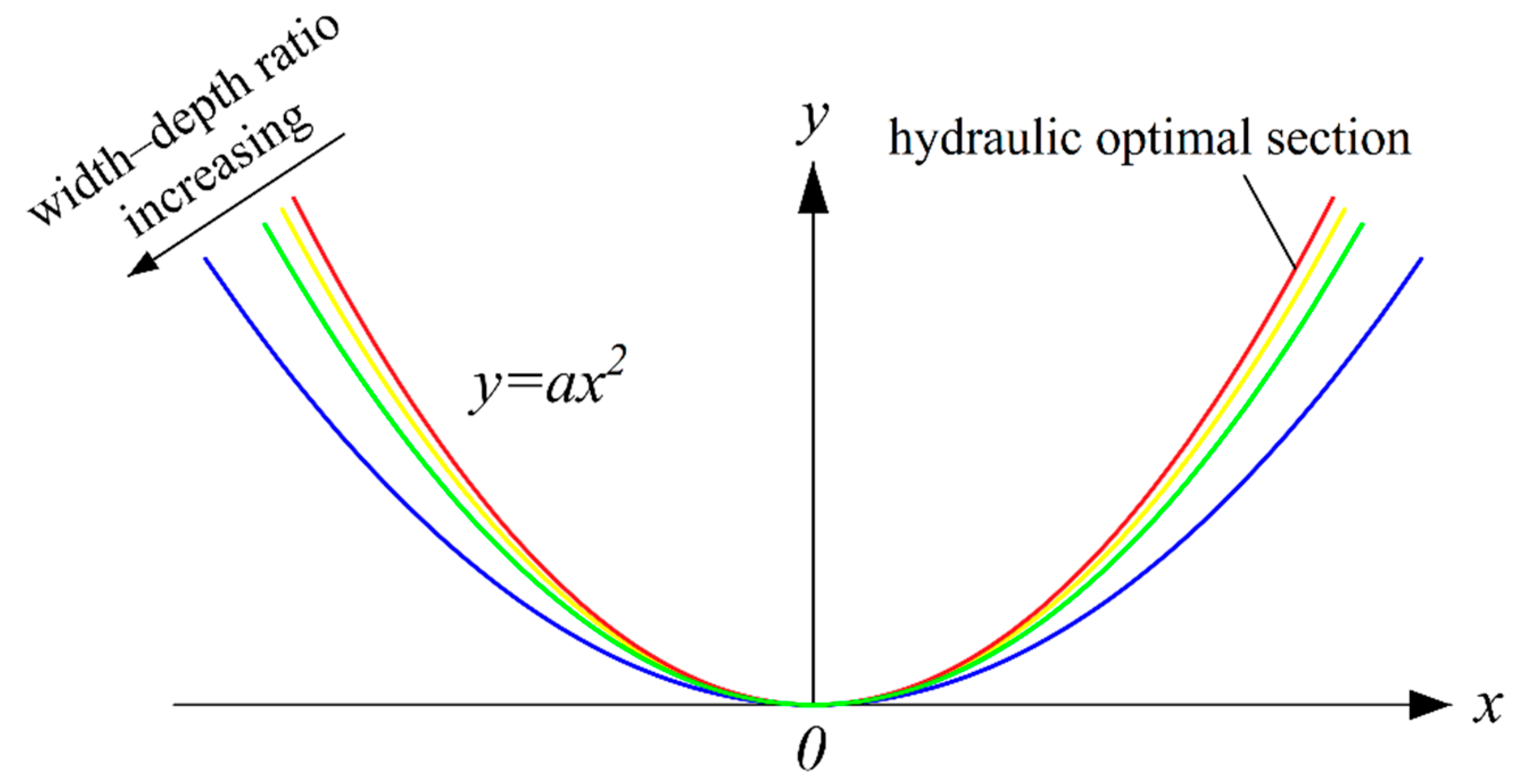
In the design of quadratic parabolic channels in seasonally frozen areas, the hydraulic performance and frost-heaving resistance should be considered. The cross sections of different parabolic channels exhibit different performances, and the width–depth ratio is an important factor that influences the cross sections. As shown in Figure 1, the hydraulic optimal section of a channel is usually narrow and deep, with a small width–depth ratio and the best hydraulic performance, but it is easily damaged by frost-heaving. With the increase in the width–depth ratio, a channel becomes wider and shallower, the extrusion force of the frozen soil on the lining gradually changes into the upward force, so the frost-heaving force becomes smaller. However, the hydraulic performance decreases. Therefore, it is necessary to establish a comprehensive optimization model to find a suitable section that can provide hydraulic performance and frost-heaving resistance.
2.1. Hydraulic Performance Analysis
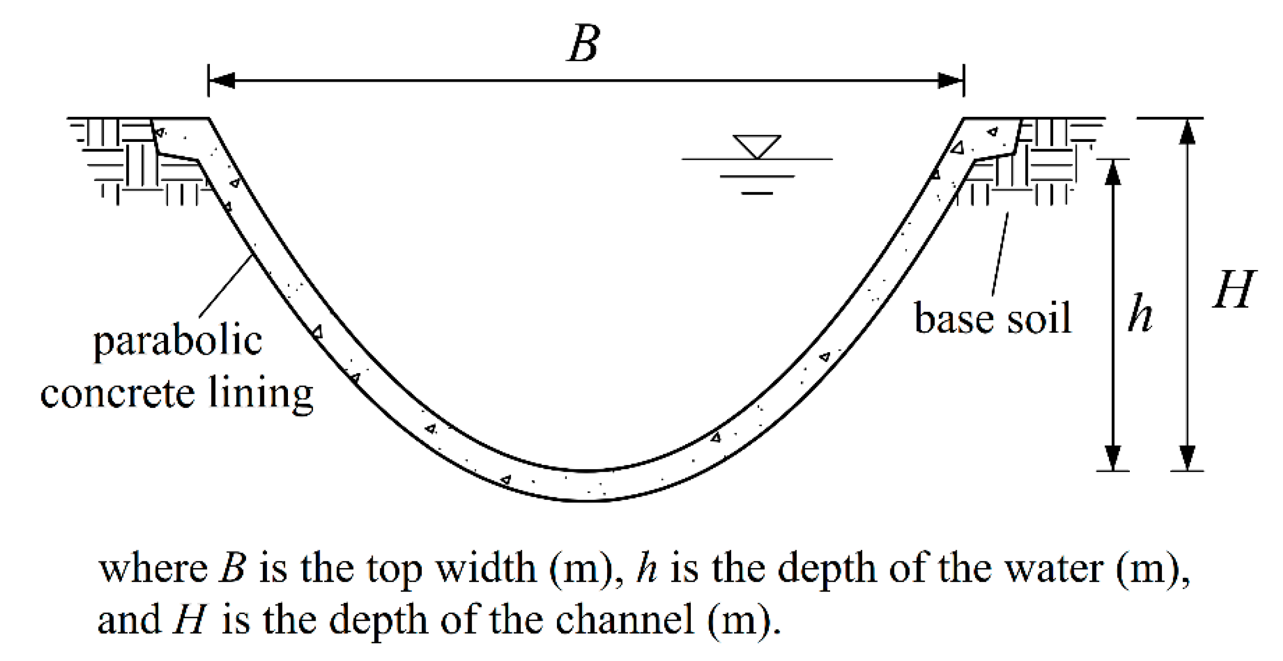
For a given design flow discharge, channel bed slope, and roughness coefficient, the hydraulic performance can be optimized by minimizing the wetted perimeter or the flow area of the channel, and the minimization of the wetted perimeter is mathematically equivalent to that of the flow area [17]. In this study, the flow area was taken as an index whose minimum value corresponded to the optimal value of the hydraulic performance. The cross section of the parabolic concrete lining channel is shown in Figure 2. The flow area function of the channel was expressed as follows:
where A is the flow area (m2), η is the width–depth ratio, η = B/H, and f1 is the function.
2.2. Frost-Heaving Resistance Analysis
The concrete lining plate of the channel could be regarded as a compression-flexure member under the joint action of frost-heaving and the freezing force. Since the tensile strength of concrete is far less than its compressive strength, the maximum tensile stress of a lining generally exceeds the ultimate tensile stress, resulting in tensile failure. The bending moment is the main factor that affects the stress, and the position of the maximum bending moment is where lining damage occurs. Based on past research and practical engineering damage knowledge [18,19], it is known that concrete lining channels generally experience bulging damage near the bottom 1/3 of the slope and channel bottom extrusion damage. This indicated that the maximum negative bending moment would occur near the bottom 1/3 of the channel slope, and the maximum positive bending moment would occur at the bottom of the channel, as shown in Figure 3. To achieve a uniform force on the channel lining section with a uniform thickness of the lining plate, the absolute value of the difference between the maximum positive and negative bending moments on the lining plate had to be as small as possible [16], which could be represented as follows:
where M1max is the maximum positive bending moment (kN·m), M2max is the maximum negative bending moment (kN·m), and f2 is the function.
3. Comprehensive Optimization Model
3.1. The Objective Function
Through the above analysis, it was found that the minimum value of the flow area was the optimization objective for the hydraulic performance, and the minimum value of the absolute value of the difference between the maximum positive and negative bending moments was the optimization objective for the frost-heaving resistance. The following objective function could be established:
3.2. Restrictions
3.2.1. Flow Velocity Constraint
A flow velocity that is too slow will lead to sediment accumulation in the channel, reduce the capacity of water transport, and increase the load of the channel, while a flow velocity that is too fast will cause channel scour. Therefore, to ensure the long-term safe operation of the channel, the channel must not accumulate silt or erode [20]. The flow velocity constraint could be expressed as:
where v is the average flow velocity (m/s), v = Q/A, v1 is the no-silting-allowed flow velocity (m/s), and v2 is the no-scour-allowed flow velocity (m/s).
3.2.2. Width–Depth Ratio Constraint
The width–depth ratio of the section has a great influence on the long-term operation of the channel, so it has to be restricted within a certain range [21]. The width–depth ratio constraint could be expressed as:
where η1 and η2 are the lower and upper limits of the width–depth ratio, respectively (Generally, the value of η1 and η2 for small channels are respectively equal to 1.5 and 3 [22]).
3.2.3. Crack Resistance Constraint
The concrete lining plate had to meet the requirement of crack resistance. In other words, the maximum tensile stress could not exceed the ultimate tensile stress [12]. For the combined deformation problem of pressing and bending, the expression of the tensile stress is shown as follows:
where σ is the tensile stress (Pa), M is the bending moment (N·m), N is the axial force (N), and b is the thickness of the concrete lining (generally 0.6–0.8 m).
It could be seen from the above equation that the axial force had little influence on the stress, and as can be seen from the force distribution in Figure 4, the axial forces at the bottom and at the lower 1/3 of the channel were both pressures, indicating that the N value was positive. Then, to simplify the calculation and to be cautious in our computation, the axial force was ignored in the calculation. According to the crack resistance conditions,
where Ec is the elastic modulus of concrete and εt is the ultimate tensile strain, both of which could be selected according to the table of the concrete label [23] (C20 or C25 are generally used for the strength of a concrete lining board).
Then, it could be deduced that
The crack resistance constraint conditions of the maximum positive and negative bending moments were as follows:
3.3. Linear Weighted Sum Method
The linear weighted sum method could transform the multi-objective problem into a single-objective programming problem and take the optimal solution as the optimal solution of the multi-objective problem. When multiple targets were maximized or minimized, the weight of each target fk(X) could be given a different weight, λk, depending on the importance of each target function. The weighted sum of each target function was calculated as the new target function. Compared with other methods, this method has the advantages of ease of computation and a high search efficiency. The single-objective model constructed by the multi-objective programming model could be expressed as [24]
where λ = (λ1,λ2,…,λp)T is the weight vector, U(X) is the evaluation function.
If the optimal solution of the single-objective model was to become an effective solution of the multi-objective model, the weight had to meet the following requirements:
The key to using the linear sum method was to determine the weight of each objective function. The main methods were the α method, λ method, and sorting method. In this study, the weight was determined with the α method. The premise of using the α method was that there is no absolute optimal solution to the multi-objective programming problem. The specific solution process was as follows:
First, the optimal solution of p single-objective problems was found as Xk and recorded as . In the target space, a hyperplane was drawn through p points and the equation was set to:
The equation set was obtained:
It was assumed that A = [fki] was a p × p-order matrix and e = (1,1,…,1)T was an n-dimensional row vector with elements 1, λ = (λ1, λ2, …, λp)T. When the multi-objective programming model had no absolute optimal solution, the matrix A was invertible, and the solution of the equation set shown in Equation (13) was
After obtaining λ1,λ2,…,λp, the single-objective programming problem could be solved.
4. Objective Function Calculation
4.1. Calculation of Flow Area
To determine expressions for the quadratic parabolic channel flow area with the width–depth ratio, the flow discharge, channel bed slope, and the roughness coefficients, the flow area was first calculated based on the cross section, as follows:
where B is the top width (m), h is the depth of the water (m), and a is the parabolic coefficient. h was the only unknown in the expression.
The wetted perimeter was calculated based on the cross section as follows:
where χ is the wetted perimeter (m).
The formula for uniform open-channel flow was as follows [25]:
where Q is the flow discharge (m3/s), i is the channel bed slope, and n is the roughness coefficient.
By substituting Equations (15) and (16) into Equation (17), h could be obtained as follows:
By inserting Equation (18) into Equation (15), we could obtain an expression for the parabolic channel flow area containing the width–depth ratio and the coefficients such as the flow discharge, as follows:
4.2. Calculation of Force and Bending Moment
4.2.1. Force Analysis
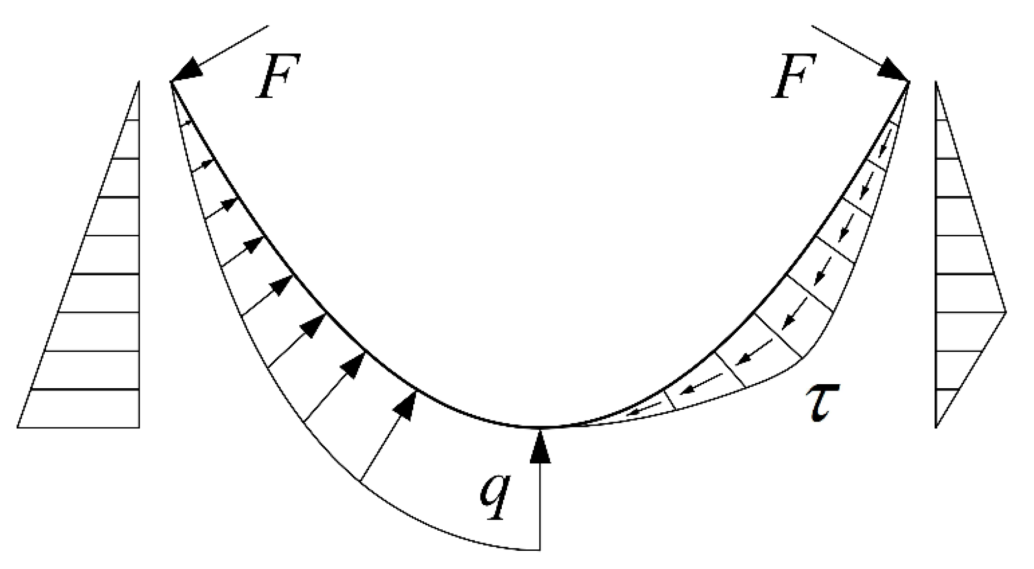
The distribution of the frost-heaving force was assumed to be symmetrical, and the differences between shady and sunny slopes were not considered. The elastic modulus of the frozen soil was much smaller than that of concrete. Thus, the soil was assumed to exert a frost-heaving force (only on the lining board) and to provide a passive freezing constraint [12]. According to the hypotheses of Xin et al. [16] and Li et al. [13] about the mechanical model of a U-shaped channel, the normal frost-heaving force had a maximum value q at the bottom of the channel and a minimum value of 0 at the top of the channel. Furthermore, the force was distributed linearly along the flat region of the lining and uniformly at the arc bottom. The tangential freezing forces were zero at the bottom and top of the channel and they reached a maximum value of τ at the junction of the arc region and the flat region, which varied linearly along the lining. The normal freezing force was at the top of the channel and it acted perpendicular to the channel slope, and the magnitude was 1/3 qL (where L is the length of the flat region of the U-shaped channel). Based on this, a mechanical model of a parabolic channel could be constructed; the parabola continuously changed. The parabolic channel had a small slope, curvature change, and depth change at the bottom of the channel and a large slope, small curvature change, and a nearly linear shape at the top of the channel. Therefore, as shown in Figure 4, the normal frost-heaving force of the parabolic channel varied linearly with the depth, with a maximum value q at the bottom and a minimum value of zero at the top. The tangential freezing force was zero at the top and bottom of the channel and it reached a maximum of τ in the lower 1/3 of the channel, varying linearly with the depth. The normal freezing force F was at the top of the channel and it acted perpendicular to the channel slope. The maximum value of F had to be less than or equal to the freezing force of the soil under the local conditions at that time [26]; this was calculated as 1/7 qh.
4.2.2. Force Calculation
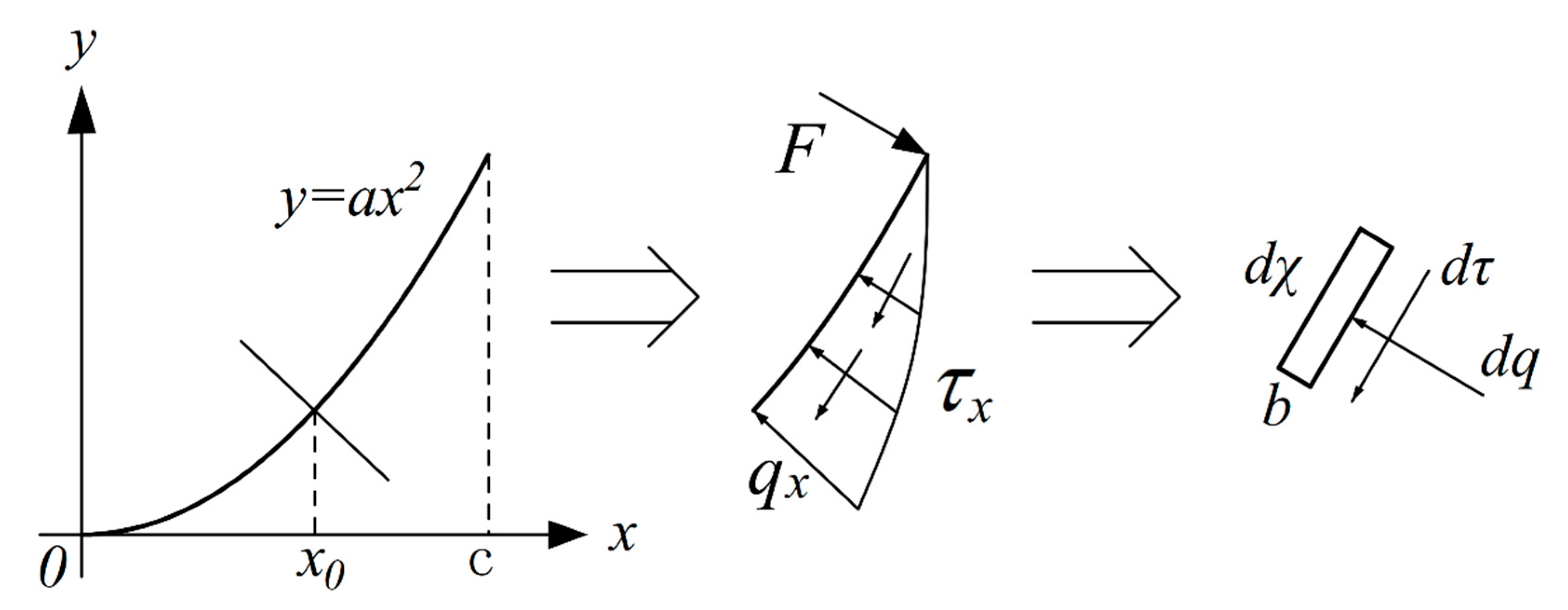
Taking the channel bottom as the origin of the coordinates, a Cartesian coordinate system was established. The lining board was a thin shell structure with left and right symmetry, and the right side was taken for calculation, as shown in Figure 5. The calculation had to satisfy the following balance equation (ignoring the weight of the lining):
where Fy is the force in the y direction (kN).
The magnitude of the infinitesimal normal frost-heaving force was , and the vertical force component was . By integrating, the vertical component of the normal frost-heaving force could be obtained as follows:
where q is the maximum value of normal frost-heaving force (N/m), c is half of the channel opening width (m), k is the parabolic exponent, and a is the parabolic coefficient.
For , the magnitude of the infinitesimal tangential freezing force was , and the vertical force component was . For , , and the vertical force component was . By integrating, the vertical component of the tangential freezing force could be obtained as follows:
The normal freezing force was 1/7qh, and this force was factored into the vertical direction as follows:
According to force balance Fdz – F – Fdj = 0, and ac = 2/η. By substituting Equations (21)–(23) into the force balance, the following formula could be obtained:
4.2.3. Bending Moment Calculation
When x0 was the positive x-axis value, as shown in Figure 5, the bending moment of the normal frost-heaving force at point x0 was as follows:
The bending moment of the tangential freezing force at point x0 was as follows:
The bending moment of the normal freezing force at point x0 was as follows:
The maximum value of the negative bending moment was taken in the lower 1/3 of the channel, the maximum value of the positive bending moment was taken as the middle point of the channel bottom, and ac = 2/η. Then, the maximum positive and negative bending moments were:
The maximum tangential freezing force was closely related to various parameters, including the temperature and the soil texture, and it could be calculated using Equation (29) for negative temperatures above −20 °C [12,27]:
where t is the absolute value of the negative temperature (°C), and n and m are coefficients related to the soil texture (n = 0.3–0.6 kPa and m = 0.4–1.5 kPa/°C).
According to Equation (17) for calculating the uniform flow of the open channel, it could be deduced that:
By combining Equations (24) and (28)–(30), the absolute value of the difference between the maximum positive and negative bending moments can be calculated, so the function f2(η) can be obtained.
5. Results
The Shijin Irrigation District is located in the central and southern part of the Hebei province, and it is a seasonally frozen area. The head channel in the Liangjiazhuang project area uses a parabolic concrete lining channel, which has a design flow discharge of Q = 0.35 m3/s, roughness coefficient of n = 0.017, channel bed slope of i = 1/3000, parabolic equation of y = 0.86x2, water depth of h = 0.62 m, and channel width of B = 1.7 m. The no-silting-allowed flow velocity is v1 = 0.4 m/s, and the no-scour-allowed flow velocity is v2 = 2.5 m/s. The lining is C20 concrete and the thickness of the lining board is 6 cm.
Based on the design flow discharge and other conditions of the head channel, the parabolic comprehensive optimal section could be designed. The local minimum negative temperature was taken as −16 °C, and the parameters of the soil texture were taken as n = 0.4 kPa and m = 0.6 kPa/°C. The maximum tangential freezing force was calculated to be 10 kPa, and the bending moment was calculated.
By calculation, the function f1(η) had a minimum value of 0.6905 at 2.055, and the function f2(η) had a minimum value of 0 at 2.26. Then,
The effective solution was between 2.055 and 2.26. Then, the weight was calculated with the above linear weighted sum method, which was
Then, the multi-objective function was converted into a single-objective function, as follows:
As shown in Figure 6, the evaluation function U(η) was represented as a group of lines parallel to line 1. When U(η) was changed to move the line to line 2 tangent to the target function domain f(η), U(η) reached its minimum value. The coordinates of the tangency point C in the figure are the corresponding values of the two target functions.
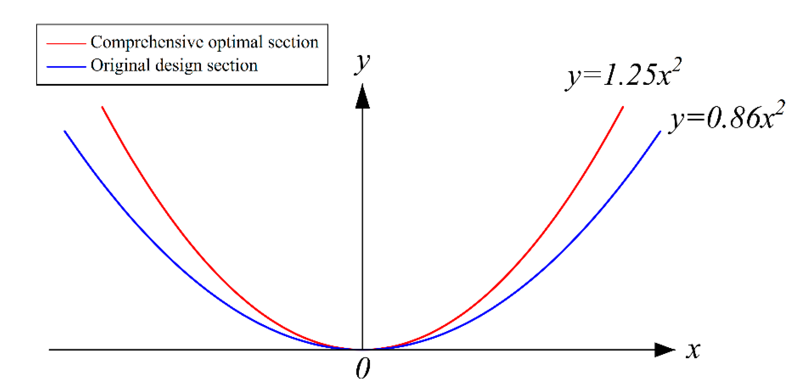
It could be calculated that U(η) had the minimum value of η = 2.15. Therefore, the optimal section was a quadratic parabolic channel with a width–depth ratio of 2.15. Then, we determined that a = 1.25, h = 0.69 m, B = 1.49 m, and the parabolic equation was y = 1.25x2. The designed comprehensive optimal section was compared with the original design section in the Shijin Irrigation District. The results were as shown in Table 1. The cross sections of the two types of channels are shown in Figure 7.
As shown in Table 1, the comprehensive optimal section was compared with the original design section of the Shijin Irrigation District. For the optimal section, the width–depth ratio was smaller, the parabolic coefficient was larger, and the water depth increased by 11.29%. Furthermore, the width of the channel, the flow area, and the maximum positive and negative bending moment difference were 12.35%, 1.96%, and 23.2% smaller, respectively, for the optimal channel. This indicated that the comprehensive optimal section exhibited a better hydraulic performance, a more uniform force distribution, and lower land use. Although the force on the original design section of the Shijin Irrigation District was smaller, the force uniformity, land use area, and hydraulic performance were much poorer, indicating that the original design section was too wide and shallow.
6. Discussion
6.1. Comparison of Several Typical Parabolic Sections
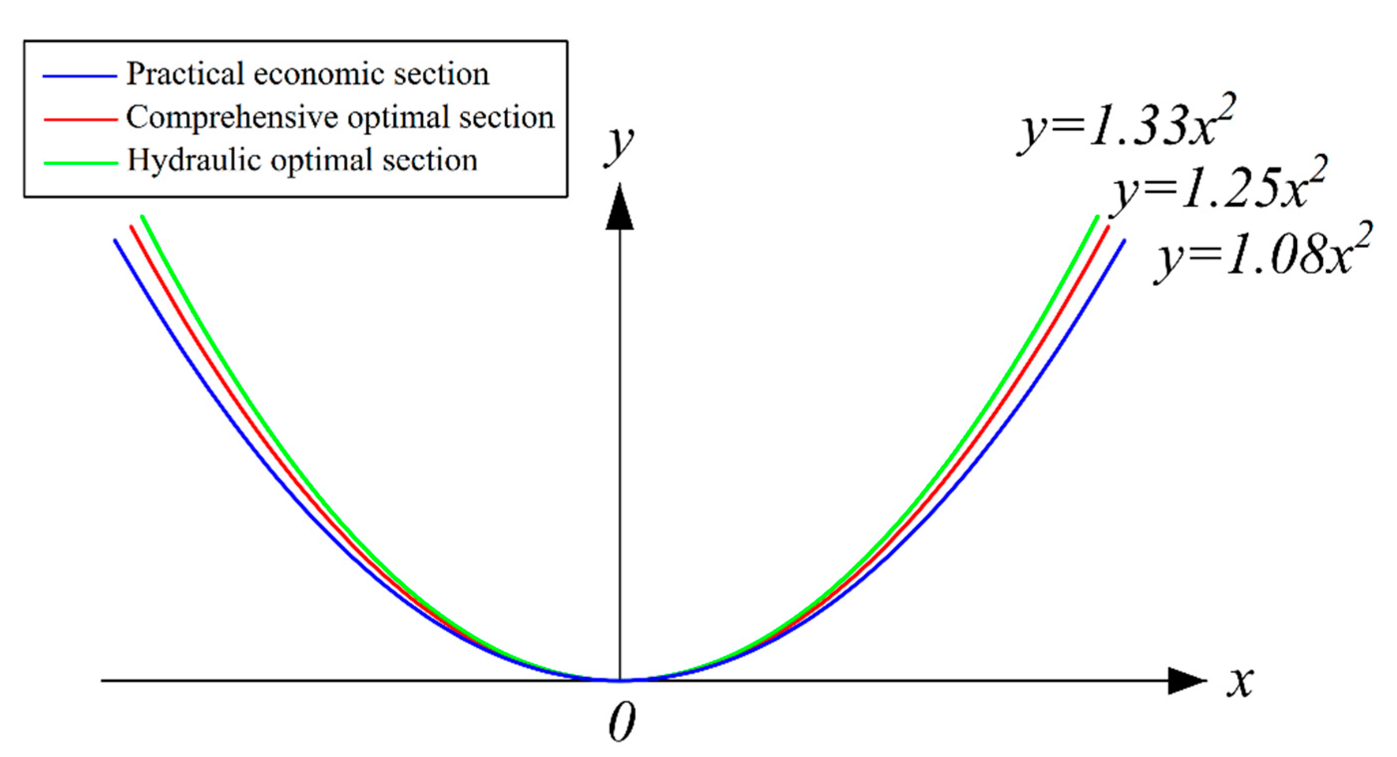
To illustrate the feasibility of the parabolic comprehensive optimal section proposed in this study, the comprehensive optimal section described above was compared with the hydraulic optimal section and the practical economic section (α = 1.04) for the same design conditions. The results are shown in Table 2, and the cross sections of the three types of channels are shown in Figure 8.
As shown in Table 2, the parameters of the comprehensive optimal section were between those of the hydraulic optimal section and the practical economic section. First, the comprehensive optimal section was compared with the hydraulic optimal section. For the comprehensive optimal section, the width–depth ratio was larger, and the parabolic coefficient was smaller. Furthermore, the width of the channel and the flow area increased by 2.05% and 0.02%, respectively. The water depth decreased by 2.82%. The maximum positive bending moment, maximum negative bending moment and their difference decreased by 5.6%, 11.89%, and 7.62%, respectively. This indicated that the comprehensive optimal section was wider and shallower, with a smaller and more uniform force; furthermore, it had better frost-heaving resistance.
The comprehensive optimal section was compared with the practical economic section. For the comprehensive optimal section, the width–depth ratio was smaller, the parabolic coefficient was larger, and the water depth increased by 4.55%. Furthermore, the width of the channel, the flow area, and the maximum positive and negative bending moment difference decreased by 4.49%, 0.2%, and 1.79%, respectively. This indicated that the comprehensive optimal section occupied less land area, it had a more uniform force distribution, and it exhibited a better hydraulic performance.
6.2. Application Analysis
The optimal design of a channel section in a seasonally frozen area is directly related to the cost, water resource utilization and project benefits of the channel project. In practice, various physical and mechanical indices of frozen soil vary significantly, and they are difficult to obtain accurately. To make the channel more convenient to design, in this study, the parabolic channel mechanics model was improved based on the predecessors, the force distribution law of the channel frost-heaving damage was analyzed, and the bending moment was calculated. The mechanical model was clear and intuitive, and it could better reflect the actual frost-heaving damage. In addition, the model could be calculated using the actual negative temperature and soil conditions and the model had no direct relationship with other complicated physical and mechanical indices of frozen soil. Thus, the determination of various related physical and mechanical indices through a large number of complicated indoor and outdoor tests could be avoided, which simplified the problem.
In recent years, with the increase in labor costs and the application of new technologies and materials, channel construction technology has begun to develop toward mechanization and semi-mechanization. Parabolic channels have the advantages of good section continuity, the simplicity of fabricating a mold, high suitability for mechanized construction technology [28], and broad application prospects. In an actual construction project, a channel section design should account for the excavation and filling costs, lining costs, and other economic factors [29,30]. Furthermore, when faced with different application conditions, a channel should be designed based on the local conditions.
7. Conclusions
(1) Based on the analysis of the hydraulic performance and frost-heaving resistance of a quadratic parabolic channel, a multi-objective optimization model was established with the goal of achieving a minimum cross-sectional flow area and uniform channel section force. Taking the flow velocity, the width–depth ratio, and the crack resistance of the concrete lining plate as constraints, the α method of the linear weighted sum method was used to optimize the calculation. This optimization method combined two objective functions with different dimensions to transform the multi-objective function into a single objective function, which was simple and practical.
(2) With the design flow discharge, channel bed slope, and roughness coefficient of the parabolic head channel in the Shijin Irrigation District of the Hebei province, the comprehensive optimal section of the parabolic channel was designed, and a quadratic parabolic channel was obtained with a width–depth ratio of 2.15. The optimal section was compared with the original design section. The force uniformity of the optimal section was 23.2% better, the hydraulic performance was 1.96% better, and the land use was 12.35% less, indicating that the comprehensive optimal section was superior.
(3) For the same conditions, the comprehensive optimal section was compared with the hydraulic optimal section. The maximum positive bending moment and the maximum negative bending moment of the comprehensive optimal section decreased by 5.6% and 11.89%, respectively, and the force uniformity improved by 7.62%. The comprehensive optimal section was compared with the practical economic section. The force uniformity of the comprehensive optimal section was 1.79% better, the hydraulic performance was 0.2% better, and the land use was 4.49% less. In conclusion, the comprehensive optimal section was a section that achieved optimal hydraulic performance and frost-heaving resistance, and its design was between that of the hydraulic optimal section and the practical economic section. Thus, it could meet the application requirements of seasonally frozen areas, providing a basis for the selection and design of parabolic channels in seasonally frozen areas.
Author Contributions
Conceptualization, Z.Y.; Data curation, Z.Y.; Formal analysis, Z.Y.; Funding acquisition, W.H. and Y.W.; Investigation, W.H. and Y.W.; Methodology, Z.Y.; Project administration, W.H. and Y.W.; Resources, W.H. and Y.W.; Software, P.D.; Supervision, P.D.; Validation, Z.L.; Visualization, Z.L.; Writing—original draft, Z.Y.; Writing—review & editing, W.H., Y.W. and Z.L. All authors have read and agreed to the published version of the manuscript.
Funding
This work was financially supported by the 13th Five-Year Plan for the National Key Project of Research and Development (grant numbers 2016YFC0400203 and 2016YFC0400205).
Conflicts of Interest
The authors declare no conflict of interest.
References
- Liu, D.; Hu, Y.X.; Fu, Q.; Li, T.X. Optimization and parameter analysis for channel cross section with concrete lining in northern irrigation district. Trans. Chin. Soc. Agric. Eng. 2015, 31, 107–114. (In Chinese) [Google Scholar]
- Snell, M. Lining old irrigation canals: Thoughts and trials. Irrig. Drain. 2010, 50, 139–157. [Google Scholar] [CrossRef]
- Han, X.D.; Wang, X.G.; Zhu, Y.; Huang, J.S.; Yang, L.Q.; Chang, Z.F.; Fu, F. An experimental study on concrete and geomembrane lining effects on canal seepage in arid agricultural areas. Water 2020, 12, 2343. [Google Scholar] [CrossRef]
- Zhang, G.J.; Lu, L.G. Important factors that influence lining channel frost heaving damage. China Rural Water Hydropower 2012, 9, 105–108. (In Chinese) [Google Scholar]
- Mironenko, A.P.; Willardson, L.S.; Jenab, S.A. Parabolic canal design and analysis. J. Irrig. Drain. Eng. 1984, 110, 241–246. [Google Scholar] [CrossRef]
- Chen, B.R.; Wang, Y.; Zhao, Y.F.; Wang, Z.Z. Optimal design of hydraulic and practical cross-section of parabolic canals. J. Irrig. Drain. Eng. 2018, 37, 93–101. [Google Scholar]
- Loganathan, G.A. Optimal design of parabolic canals. J. Irrig. Drain. Eng. 1991, 117, 716–735. [Google Scholar] [CrossRef]
- Anwar, A.A.; Vries, T.T.D. Hydraulically efficient power-law channels. J. Irrig. Drain. Eng. 2003, 129, 18–26. [Google Scholar] [CrossRef]
- Vatankhah, A.R.; Valiani, A. Analytical inversion of specific energy–depth relationship in channels with parabolic cross-sections. Hydrol. Sci. J. 2011, 56, 834–840. [Google Scholar] [CrossRef]
- Han, Y.C.; Easa, S.M. Superior cubic channel section and analytical solution of best hydraulic properties. Flow Meas. Instrum. 2016, 50, 169–177. [Google Scholar] [CrossRef]
- Han, Y.C.; Easa, S.M. Exact solution of optimum hydraulic power-law section with general exponent parameter. J. Irrig. Drain. Eng. 2018, 144, 1–31. [Google Scholar] [CrossRef]
- Wang, Z.Z. Establishment and application of mechanics models of frost heaving damage of concrete lining trapezoidal open canal. Trans. Chin. Soc. Agric. Eng. 2004, 20, 24–29. (In Chinese) [Google Scholar]
- Li, C.L.; Tang, S.R.; Wang, H.Y. Mechanical model of frost-heaving damage for integral U-shaped concrete lining canal. Water Resour. Hydropower Eng. 2015, 46, 148–151. (In Chinese) [Google Scholar]
- Yu, X.M.; Shi, Z.T.; Feng, C.Q. Evaluation system of technical water supply assembly sequence in turbine maintenance based on analytic hierarchy process. Int. J. Hydroe. Energy 2018, 36, 97–100, 151. (In Chinese) [Google Scholar]
- Song, Q.L. Establishment of Mechanics and Numerical Stimulation of Frost Heaving Damage of Parabolic-Shape Canal with Concrete Lining. Master’s Thesis, Northwest A & F University, Shanxi, China, 2015. (In Chinese). [Google Scholar]
- Xin, Y.H.; Wang, Z.Z. The structural and hydraulic analysis on frost-heaving concrete lining of the u-shape canal. Water Sav. Irrig. 2008, 2, 36–38. (In Chinese) [Google Scholar]
- Monadjemi, P. General formulation of best hydraulic channel section. J. Irrig. Drain. Eng. 1994, 120, 27–35. [Google Scholar] [CrossRef]
- Chai, J.X. Damage and prevention of channel frost heaving. China Rural Water Hydropower 1985, 2, 11–13. (In Chinese) [Google Scholar]
- Li, Z.; Liu, S.H.; Feng, Y.T.; Liu, K.; Zhang, C.C. Numerical study on the effect of frost heave prevention with different canal lining structures in seasonally frozen ground regions. Cold Reg. Sci. Technol. 2013, 85, 242–249. [Google Scholar] [CrossRef]
- Shulits, S.; Corfitzen, W.E. Bed-load transportation and the stable-channel problem. Eos Trans. Am. Geophys. Union 1937, 18, 456–467. [Google Scholar] [CrossRef]
- Peng, C.L.; He, W.Q.; Wang, Y.B.; Li, G.; Zhai, D.H. Optimization method for a lap-assembled parabolic concrete channel structure. J. Irrig. Drain. Eng. 2020, 146, 1–11. [Google Scholar] [CrossRef]
- Ma, M.; Li, G.D.; Ning, J. Experimental study on flow characteristics of curved channel in small width-depth ratio conditions. Adv. Eng. Sci. 2017, 49, 38–46. (In Chinese) [Google Scholar]
- Li, A.G.; Jian, G. Anti-Seepage Engineering Techniques for Irrigation Canals; China Water Resources and Hydropower Press: Beijing, China, 1998. (In Chinese) [Google Scholar]
- Marler, R.T.; Arora, J.S. Survey of multi-objective optimization methods for engineering. Struct. Multidiscip. Optim. 2004, 26, 369–395. [Google Scholar] [CrossRef]
- Lv, H.X.; Feng, J.T. Comparison of optimum hydraulic sections in open channel. Yangtze River. 1994, 025, 42–45. (In Chinese) [Google Scholar]
- Wang, J.F.; Ma, X.; Zhou, H.B. The failure mechanism of canal lining caused by frozen and its mechanical analysis. J. Jiamusi Univ. 2006, 24, 308–311. (In Chinese) [Google Scholar]
- Wang, Z.Z.; Li, J.L.; Chen, T.; Guo, L.X.; Yao, R.F. Mechanics models of frost-heaving damage of concrete lining trapezoidal canal with arc-bottom. Trans. Chin. Soc. Agric. Eng. 2008, 24, 24–29. (In Chinese) [Google Scholar]
- Li, G.; He, W.Q.; Zhai, D.H. Calculating optimal channel cross section with parabolic slope and flat bed using the lagrangian method. J. Irrig. Drain. Eng. 2017, 36, 51–55. [Google Scholar]
- Swamee, P.K.; Mishra, G.C.; Chahar, B.R. Design of minimum earthwork cost canal sections. Water Resour. Manag. 2001, 15, 17–30. [Google Scholar] [CrossRef]
- Depeweg, H.; Urquieta, E.R. GIS tools and the design of irrigation canals. Irrig. Drain. 2004, 53, 301–314. [Google Scholar] [CrossRef]
Figure 1.
Schematic diagram of parabolic channels with different width–depth ratios.

Figure 2.
Schematic diagram of parabolic channel cross section.

Figure 3.
Schematic diagram of bending moment distribution.

Figure 4.
Schematic diagram of frost-heaving force and the freezing force distribution in the parabolic channel.
Figure 4.
Schematic diagram of frost-heaving force and the freezing force distribution in the parabolic channel.

Figure 5.
Schematic diagram of the force calculation of the micro element.

Figure 6.
Schematic diagram of the α method for determining weights.

Figure 7.
Two types of channel section forms.

Figure 8.
Three types of channel section forms.


Table 1.
Two types of channel section parameters.
| Sectional Form | Width–Depth Ratio | M1max (kN·m) | M2max (kN·m) | ||M1max|−|M2max|| (kN· m) | Flow Area A (m2) | a | h (m) | B (m) |
|---|---|---|---|---|---|---|---|---|
| Comprehensive optimal section | 2.15 | 0.118 | −0.126 | 0.008 | 0.69054 | 1.25 | 0.69 | 1.49 |
| Original design section | 2.74 | 0.089 | −0.062 | 0.027 | 0.70437 | 0.86 | 0.62 | 1.70 |
Table 2.
Three types of channel section parameters.
| Sectional Form | Width–Depth Ratio | M1max (kN·m) | M2max (kN·m) | ||M1max|−|M2max|| (kN·m) | Flow Area A (m2) | a | h (m) | B (m) |
|---|---|---|---|---|---|---|---|---|
| Hydraulic optimal section | 2.06 | 0.125 | −0.143 | 0.018 | 0.69038 | 1.33 | 0.71 | 1.46 |
| Comprehensive optimal section | 2.15 | 0.118 | −0.126 | 0.008 | 0.69054 | 1.25 | 0.69 | 1.49 |
| Practical economic section | 2.36 | 0.105 | −0.096 | 0.009 | 0.69193 | 1.08 | 0.66 | 1.56 |
© 2020 by the authors. Licensee MDPI, Basel, Switzerland. This article is an open access article distributed under the terms and conditions of the Creative Commons Attribution (CC BY) license (http://creativecommons.org/licenses/by/4.0/).
Share and Cite
MDPI and ACS Style
Yang, Z.; He, W.; Wang, Y.; Lou, Z.; Duan, P. Research on the Comprehensive Optimization of the Hydraulic Performance and Frost-Heaving Resistance of a Parabolic Channel. Water 2020, 12, 2574. https://doi.org/10.3390/w12092574
AMA Style
Yang Z, He W, Wang Y, Lou Z, Duan P. Research on the Comprehensive Optimization of the Hydraulic Performance and Frost-Heaving Resistance of a Parabolic Channel. Water. 2020; 12(9):2574. https://doi.org/10.3390/w12092574
Chicago/Turabian StyleYang, Zhuo, Wuquan He, Yubao Wang, Zongke Lou, and Pinzhang Duan. 2020. "Research on the Comprehensive Optimization of the Hydraulic Performance and Frost-Heaving Resistance of a Parabolic Channel" Water 12, no. 9: 2574. https://doi.org/10.3390/w12092574
Note that from the first issue of 2016, this journal uses article numbers instead of page numbers. See further details here.