Low Cost AIP Design in 5G Flexible Antenna Phase Array System Application

 , , ,
, , ,
Abstract
:1. Introduction
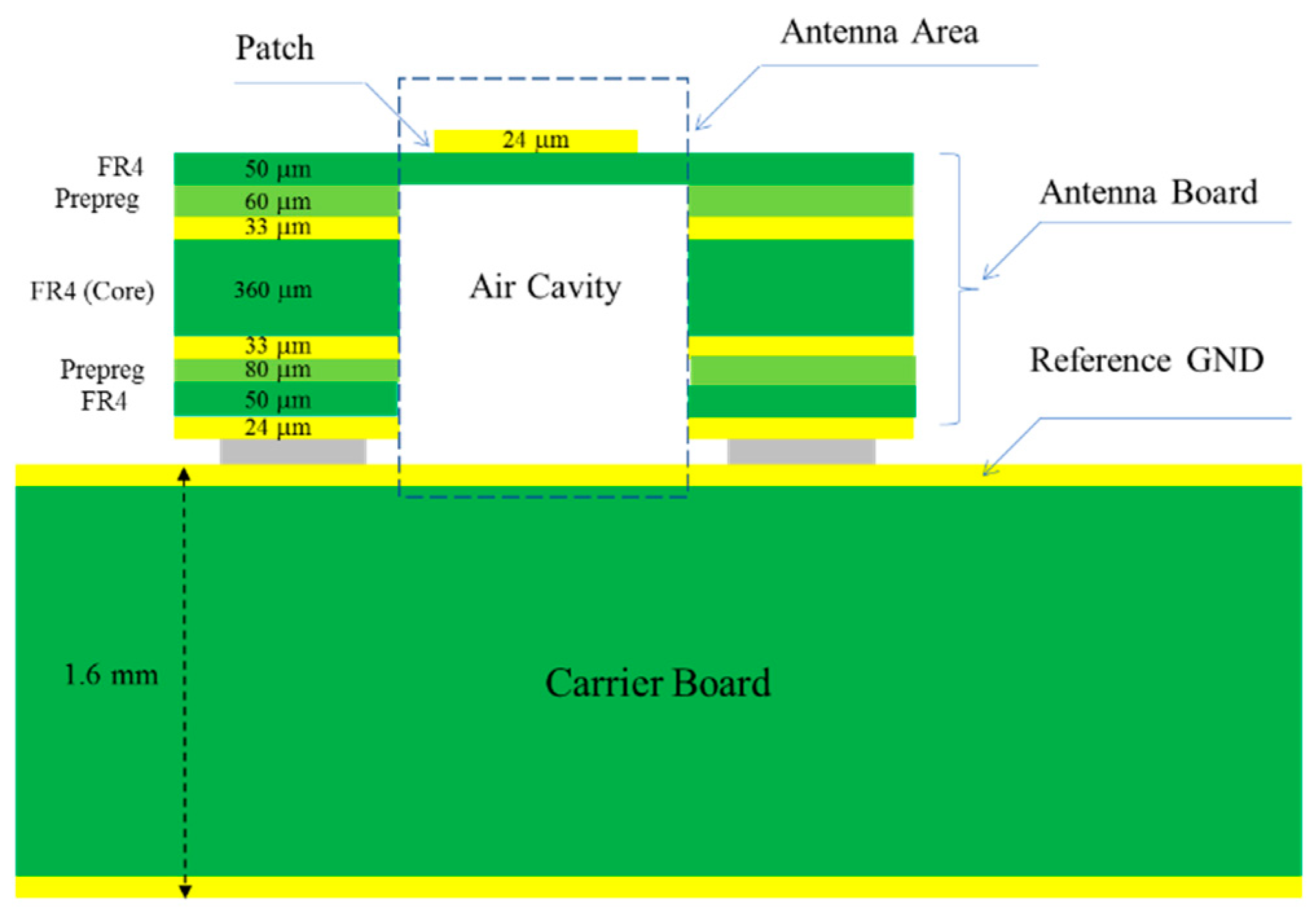
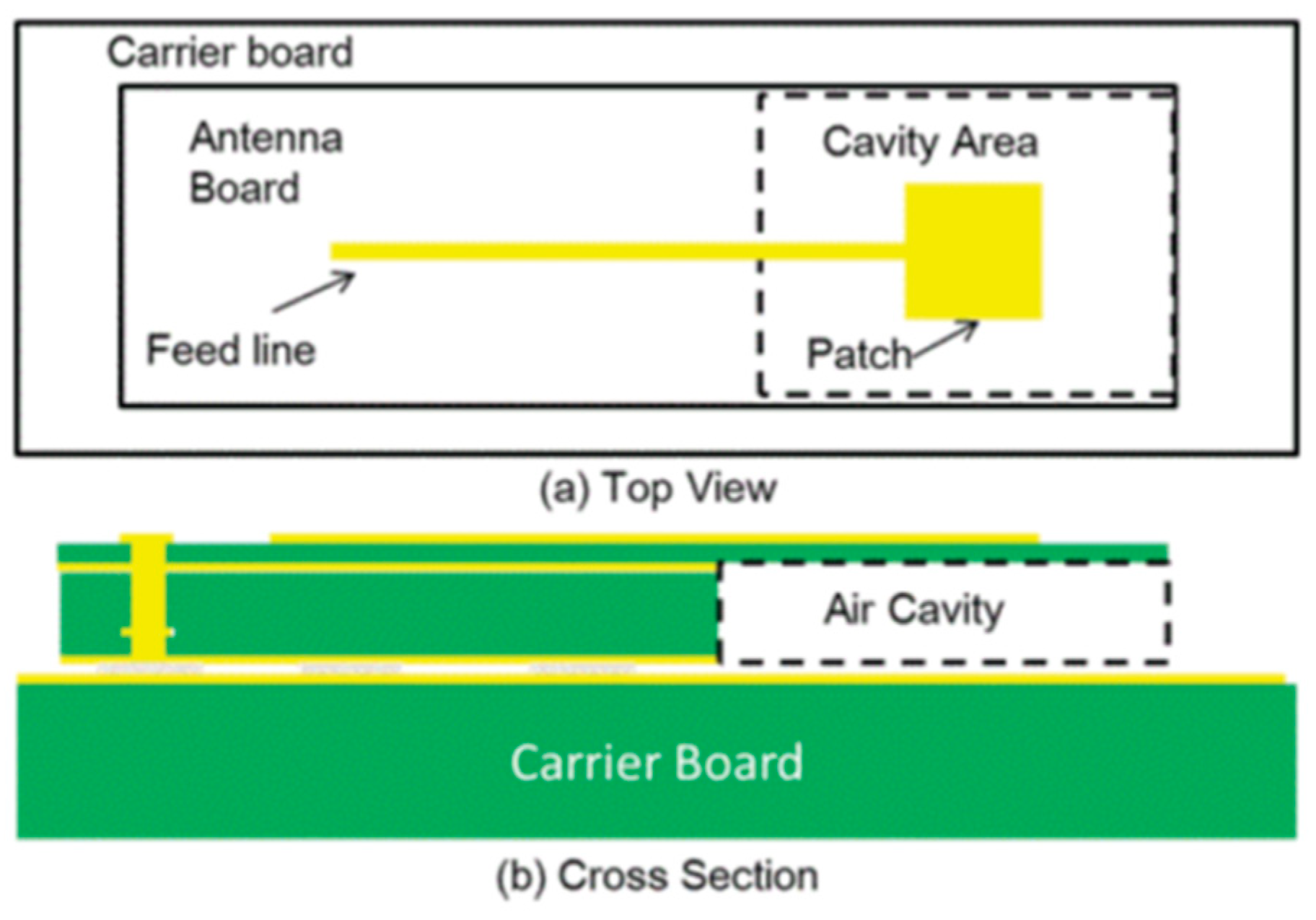
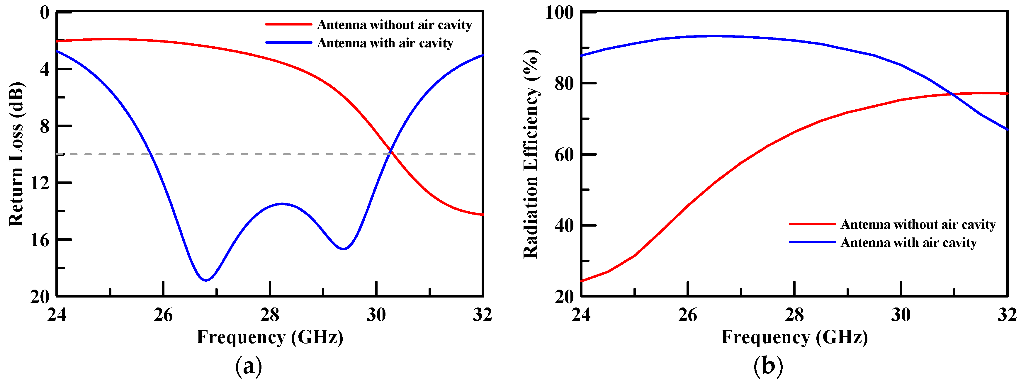
2. Patch Antenna Design
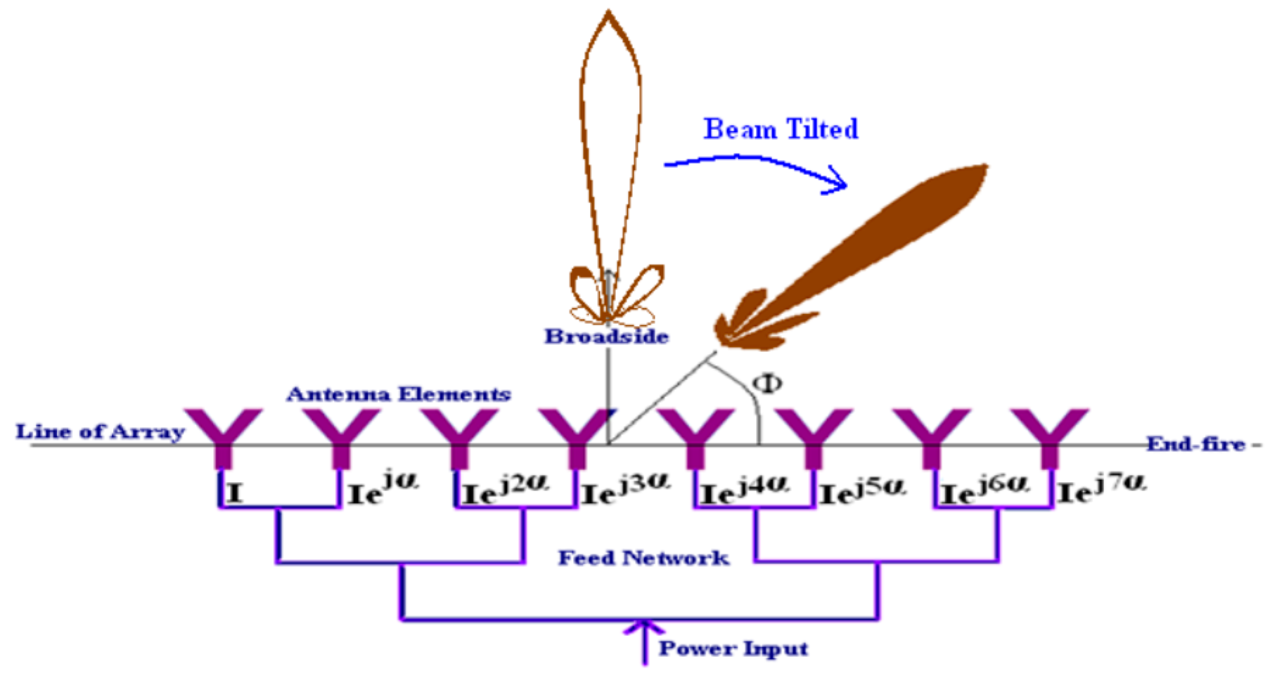
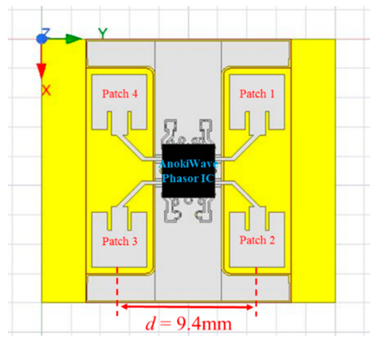
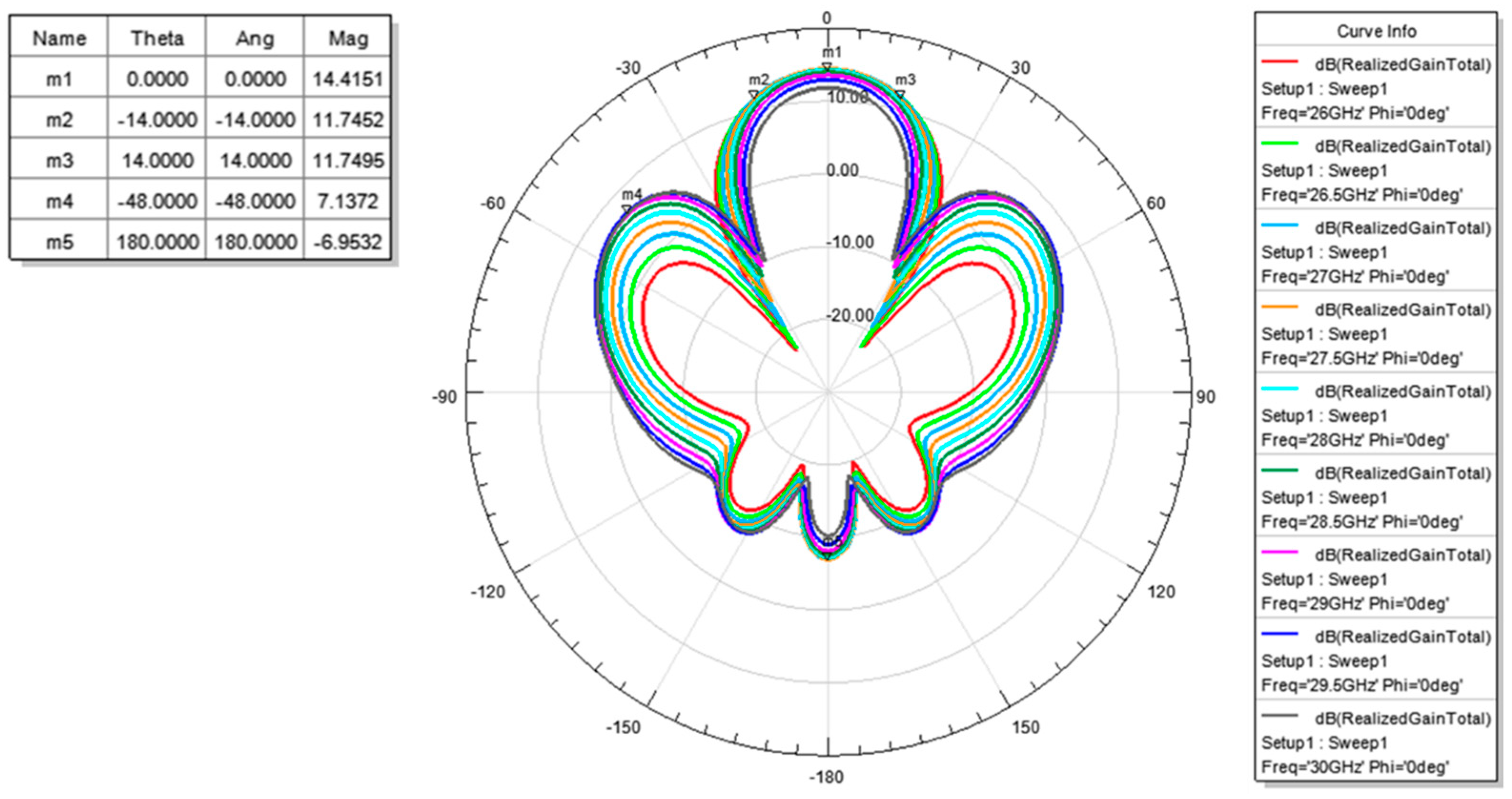
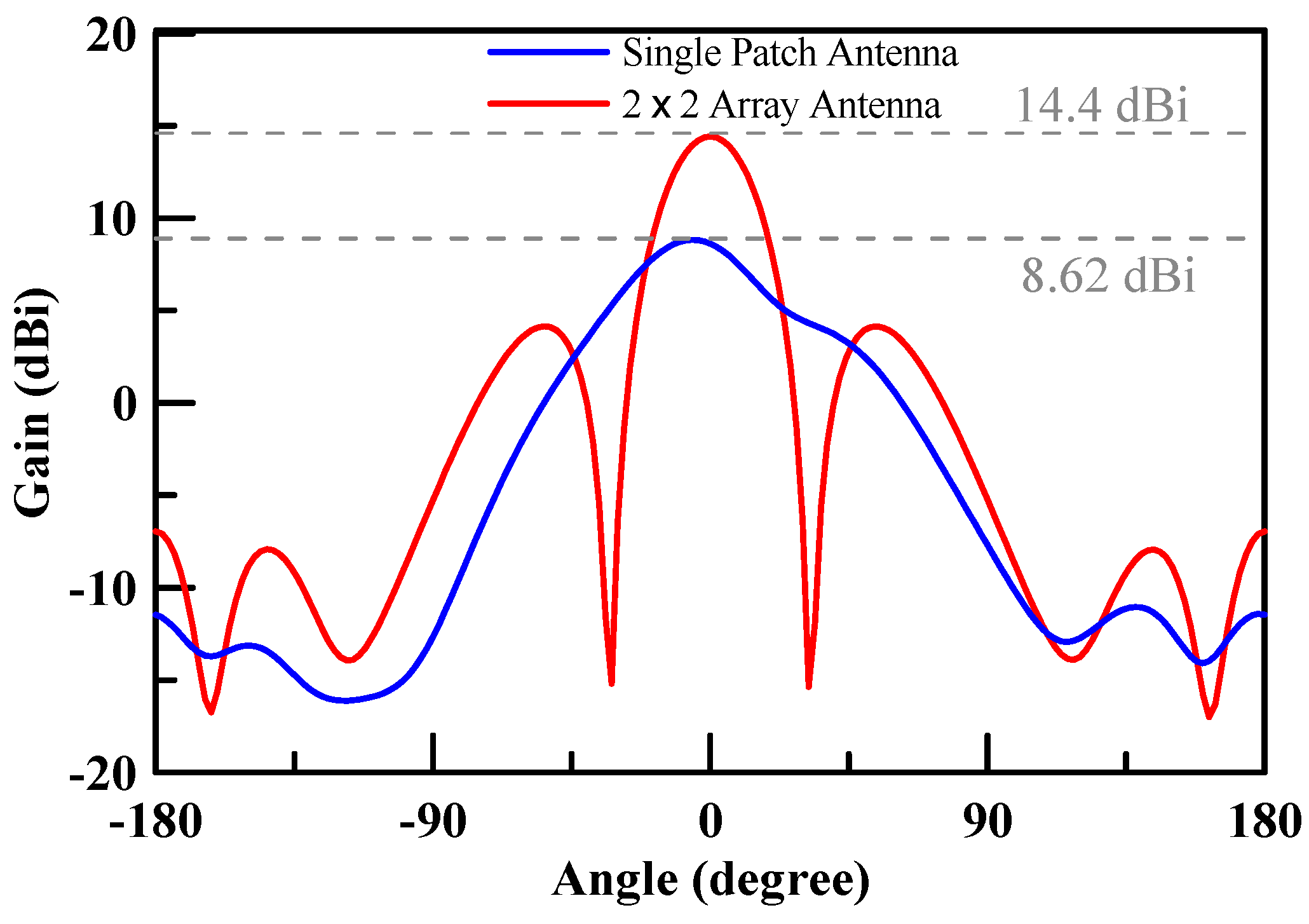
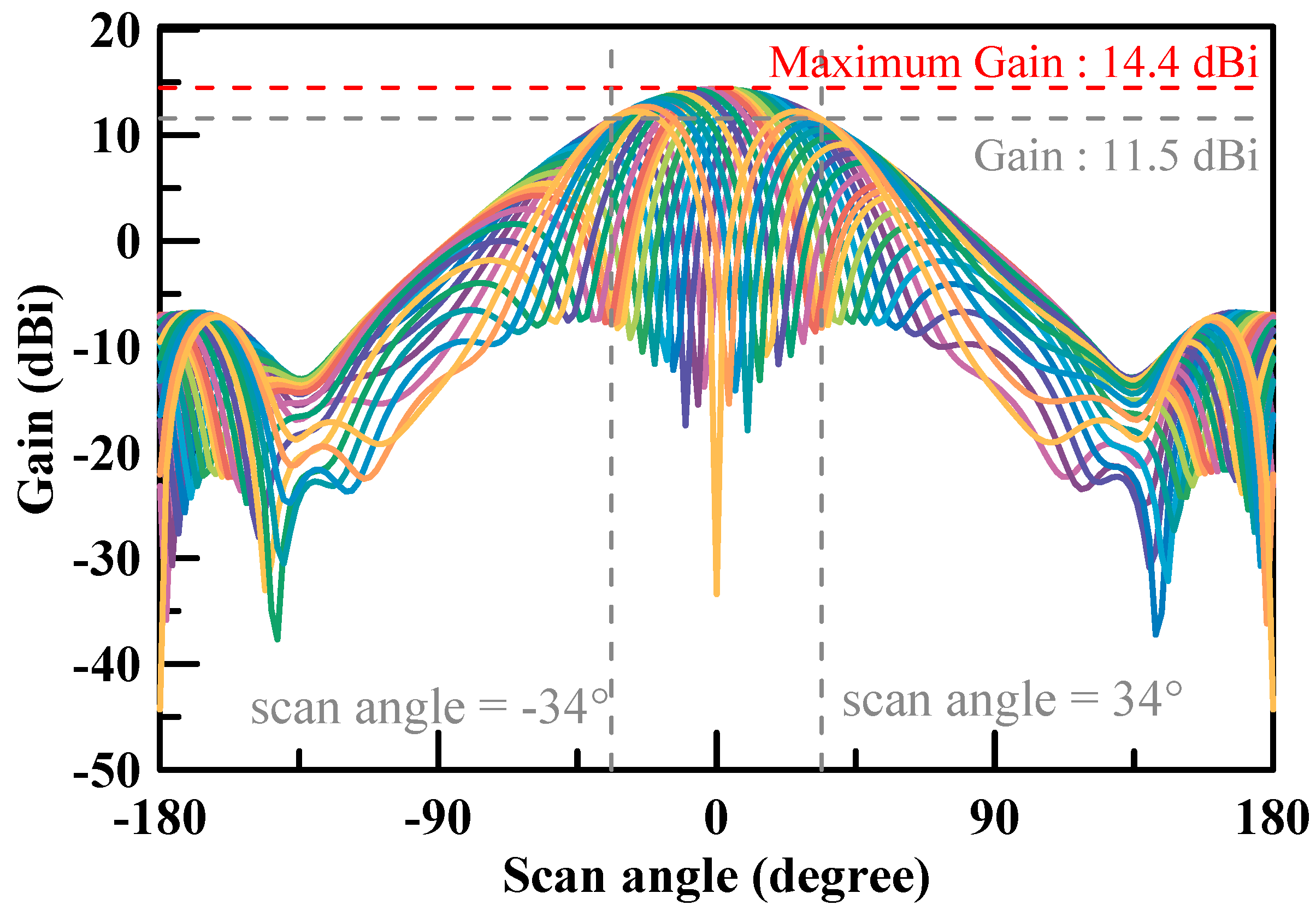
3. Array Antenna Design
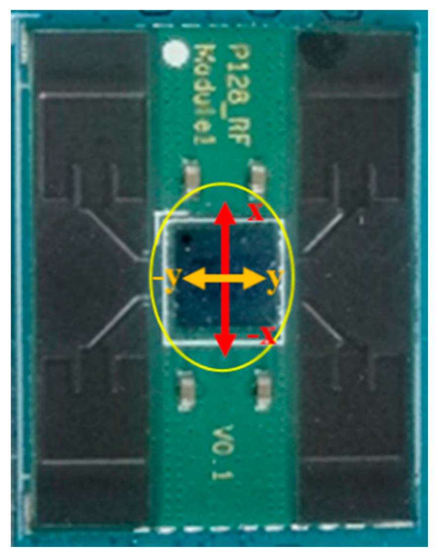
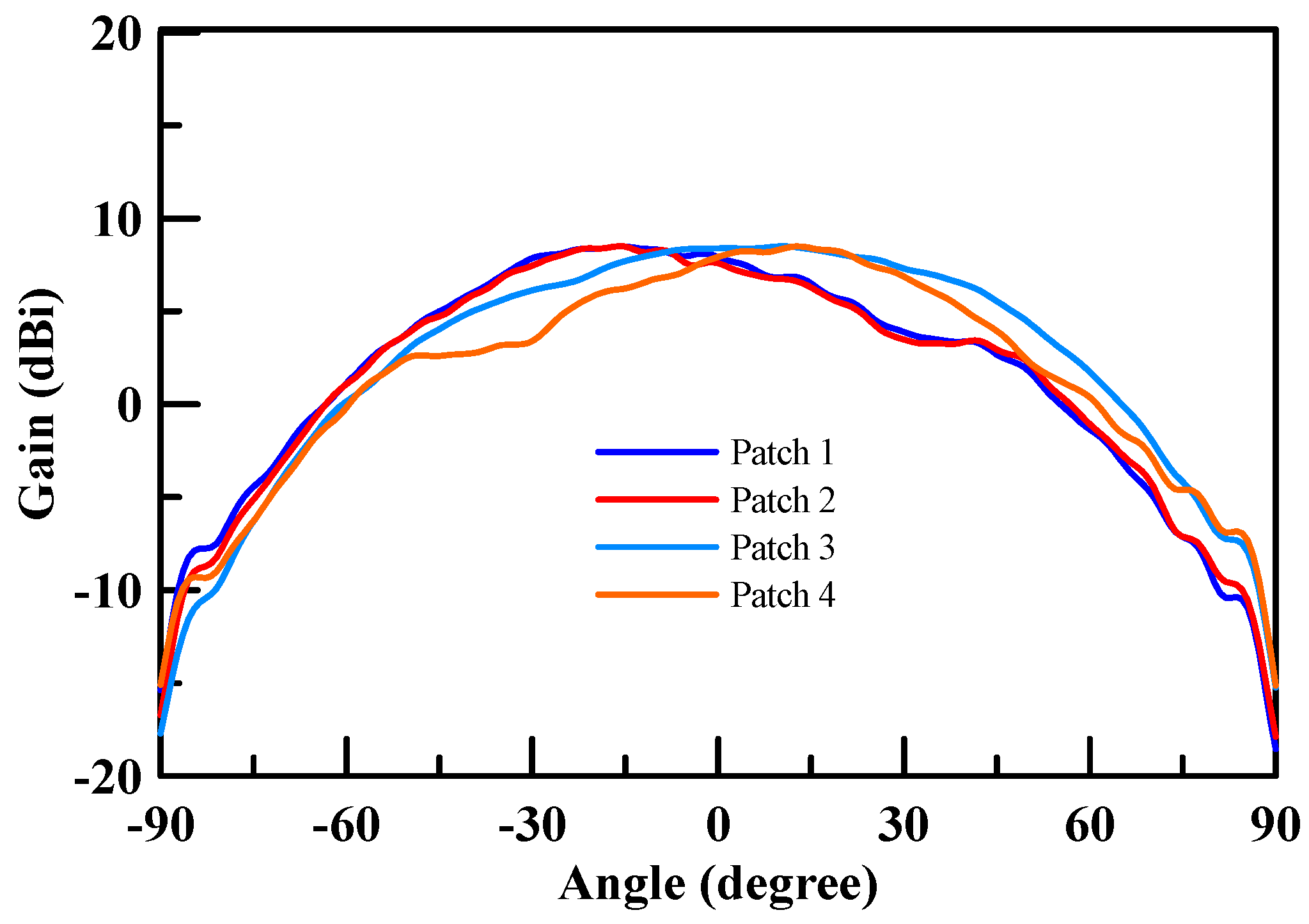
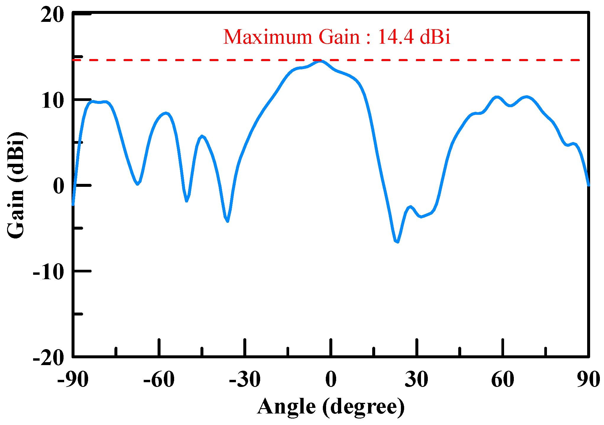
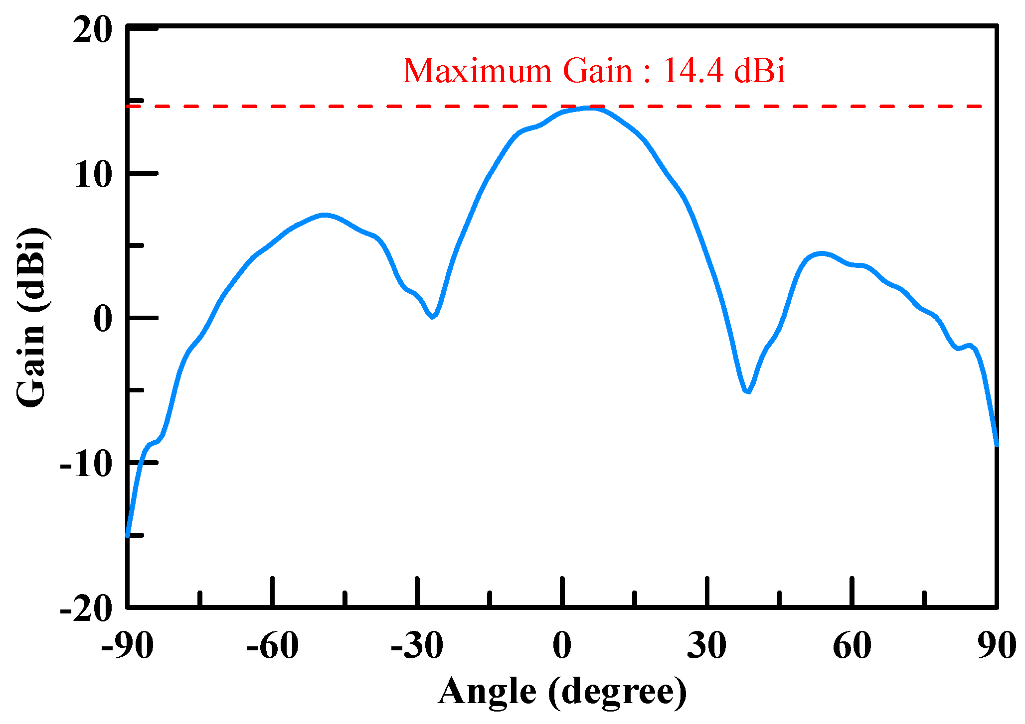
4. Antenna Manufacturing and Experimental Measurement
5. Conclusions
Author Contributions
Funding
Acknowledgments
Conflicts of Interest
References
- Ateya, A.A.; Muthanna, A.; Gudkova, I.; Id, A.A.; Vybornova, A.; Koucheryavy, A. Development of Intelligent Core Network for Tactile Internet and Future Smart Systems. J. Sens. Acuator Netw. 2018, 7, 1. [Google Scholar] [CrossRef] [Green Version]
- Szeląg, B.; Drewnowski, J.; Łagód, G.; Majerek, D.; Dacewicz, E.; Fatone, F. Soft Sensor Application in Identification of the Activated Sludge Bulking Considering the Technological and Economical Aspects of Smart Systems Functioning. Sensors 2020, 20, 1941. [Google Scholar] [CrossRef] [PubMed] [Green Version]
- Grasso, C.; Schembra, G. A Fleet of MEC UAVs to Extend a 5G Network Slice for Video Monitoring with Low-Latency Constraints. J. Sens. Actuator Netw. 2019, 8, 3. [Google Scholar] [CrossRef] [Green Version]
- Patcharamaneepakorn, P.; Wu, S.; Wang, C.-X.; Aggoune, E.-H.M.; Alwakeel, M.M.; Ge, X.; Di Renzo, M.; Aggoune, H. Spectral, Energy, and Economic Efficiency of 5G Multicell Massive MIMO Systems With Generalized Spatial Modulation. IEEE Trans. Veh. Technol. 2016, 65, 9715–9731. [Google Scholar] [CrossRef]
- Patcharamaneepakorn, P.; Wang, C.X.; Fu, Y.; Aggoune, E.H.M.; Alwakeel, M.M.; Tao, X.; Ge, X. Quadrature Space-Frequency Index Modulation Communication Systems. IEEE Trans. Commun. 2017, 66, 3050–3064. [Google Scholar] [CrossRef]
- Kibaroglu, K.; Sayginer, M.; Rebeiz, G.M. A Low-Cost Scalable 32-Element 28-GHz Phased Array Transceiver for 5G Communication Links Based on a 2×2 Beamformer Flip-Chip Unit Cell. IEEE J. Solid-State Circuits 2018, 53, 1260–1274. [Google Scholar] [CrossRef]
- Park, J.; Lee, S.Y.; Kim, J.; Park, D.; Choi, W.; Hong, W. An Optically Invisible Antenna-on-Display Concept for Millimeter-Wave 5G Cellular Devices. IEEE Trans. Antennas Propag. 2019, 67, 2942–2952. [Google Scholar] [CrossRef]
- Kumar, P.; Urooj, S.; Malibari, A.A. Design of Quad-Port Ultra-Wideband Multiple-Input-Multiple-Output Antenna with Wide Axial-Ratio Bandwidth. Sensors 2020, 20, 1174. [Google Scholar] [CrossRef] [Green Version]
- Ullah, S.; Ruan, C.; Sadiq, M.S.; Haq, T.U.; Fahad, A.K.; He, W. Super Wide Band, Defected Ground Structure (DGS), and Stepped Meander Line Antenna for Communication Applications. Sensors 2020, 20, 1735. [Google Scholar] [CrossRef] [Green Version]
- Hamberger, G.F.; Trummer, S.; Siart, U.; Eibert, T.F. A Planar Dual-Polarized Microstrip 1-D-Beamforming Antenna Array for the 24-GHz Band. IEEE Trans. Antennas Propag. 2016, 65, 142–149. [Google Scholar] [CrossRef]
- Chiang, W.-Y.; Ku, C.-H.; Chen, C.-A.; Wang, L.-Y.; Abu, P.A.; Rao, P.-Z.; Liu, C.-K.; Liao, C.-H.; Chen, S.-L. A Power-Efficient Multiband Planar USB Dongle Antenna for Wireless Sensor Networks. Sensors 2019, 19, 2568. [Google Scholar] [CrossRef] [PubMed] [Green Version]
- Chen, S.-L.; Lee, H.-Y.; Chen, C.-A.; Huang, H.-Y.; Luo, C.-H. Wireless Body Sensor Network with Adaptive Low-Power Design for Biometrics and Healthcare Applications. IEEE Syst. J. 2009, 3, 398–409. [Google Scholar] [CrossRef]
- Chen, C.-A.; Chen, S.-L.; Huang, H.-Y.; Luo, C.-H. An Asynchronous Multi-Sensor Micro Control Unit for Wireless Body Sensor Networks (WBSNs). Sensors 2011, 11, 7022–7036. [Google Scholar] [CrossRef] [Green Version]
- Wang, L.-H.; Zhang, W.; Guan, M.-H.; Jiang, S.-Y.; Fan, M.-H.; Abu, P.A.; Chen, C.-A.; Chen, S.-L. A Low-Power High-Data-Transmission Multi-Lead ECG Acquisition Sensor System. Sensors 2019, 19, 4996. [Google Scholar] [CrossRef] [PubMed] [Green Version]
- Chen, C.-A.; Wu, C.; Abu, P.A.; Chen, S.-L. VLSI Implementation of an Efficient Lossless EEG Compression Design for Wireless Body Area Network. Appl. Sci. 2018, 8, 1474. [Google Scholar] [CrossRef] [Green Version]
- Chen, C.-A.; Chen, S.-L.; Huang, H.-Y.; Luo, C.-H. An Efficient Micro Control Unit with a Reconfigurable Filter Design for Wireless Body Sensor Networks (WBSNs). Sensors 2012, 12, 16211–16227. [Google Scholar] [CrossRef] [Green Version]
- Chen, S.-L.; Wu, G.-S. A Cost and Power Efficient Image Compressor VLSI Design with Fuzzy Decision and Block Partition for Wireless Sensor Networks. IEEE Sens. J. 2017, 17, 4999–5007. [Google Scholar] [CrossRef]
- Chen, S.-L. A Power-Efficient Adaptive Fuzzy Resolution Control System for Wireless Body Sensor Networks. IEEE Access 2015, 3, 743–751. [Google Scholar] [CrossRef]
- Chen, S.-L.; Tuan, M.-C.; Lee, H.-Y.; Lin, T.-L. VLSI Implementation of a Cost-Efficient Micro Control Unit with an Asymmetric Encryption for Wireless Body Sensor Networks. IEEE Access 2017, 5, 4077–4086. [Google Scholar] [CrossRef]
- Taylor, W.; Shah, S.A.; Dashtipour, K.; Zahid, A.; Abbasi, Q.; Imran, M. An Intelligent Non-Invasive Real-Time Human Activity Recognition System for Next-Generation Healthcare. Sensors 2020, 20, 2653. [Google Scholar] [CrossRef]
- “3GPP Specification Series: 38series”. 3GPP. Available online: https://www.3gpp.org/DynaReport/38-series.htm (accessed on 22 February 2019).
- David, K.C. Field and Wave Electromagnetics, 2nd ed.; Addison-Wesley Publishing Company: Reading, MA, USA, 1989. [Google Scholar]
- Tung, W.-S.; Rao, P.-Z.; Chen, W.-M. A millimeter-wave antenna on low cost FR4 substrate. In Proceedings of the 2019 IEEE Asia-Pacific Microwave Conference (APMC), Singapore, 10–13 December 2019. [Google Scholar]
- Roy, J.S. Multiple-Antenna Techniques in Wireless Communication-Technical Aspects. Int. J. Inf. Commun. Technol. Digit. Converg. 2016, 1, 24–32. [Google Scholar]
- Stutzman, W.L.; Thiele, G.A. Antenna Theory and Design, 3rd ed.; John Wiley & Sons Inc.: Hoboken, NJ, USA, 2012. [Google Scholar]
- Henderson, R.; Pierce, R.; Aroor, S.; Arzola, J.; Miller, C.; Kumar, H.; Ei, T.; Blanchard, A.; Fooshe, D.; Schluper, B.; et al. Millimeter-wave performance of broadband aperture antenna on laminates. In Proceedings of the AMTA 2015, Long Beach, CA, USA, 11–16 October 2015. [Google Scholar]
- Fan, Y.; Wang, J.; Li, Y.; Zhang, J.; Han, Y.; Qu, S. Low-RCS and High-Gain Circularly Polarized Metasurface Antenna. IEEE Trans. Antennas Propag. 2019, 67, 7197–7203. [Google Scholar] [CrossRef]
- Chang, L.; Li, Y.; Zhang, Z.; Wang, S.; Feng, Z. Planar Air-Filled Terahertz Antenna Array Based on Channelized Coplanar Waveguide Using Hierarchical Silicon Bulk Micromachining. IEEE Trans. Antennas Propag. 2018, 66, 5318–5325. [Google Scholar] [CrossRef]
- Zhang, T.; Li, L.; Xie, M.; Xia, H.; Ma, X.; Cui, T.J. Low-Cost Aperture-Coupled 60-GHz-Phased Matching Network. IEEE Trans. Antennas Propag. 2017, 65, 6355–6362. [Google Scholar] [CrossRef]
- Zhang, T.; Li, L.; Xia, H.; Ma, X.; Cui, T.J. A Low-Cost and High-Gain 60-GHz Differential Phased Array Antenna in PCB Process. IEEE Trans. Compon. Packag. Manuf. Technol. 2018, 8, 1281–1291. [Google Scholar] [CrossRef]
- Lee, H.; Kim, S.; Choi, J. A 28 GHz 5G Phased Array Antenna with Air-Hole Slots for Beam Width Enhancement. Appl. Sci. 2019, 9, 4204. [Google Scholar] [CrossRef] [Green Version]
- Liu, D.; Gu, X.; Baks, C.W.; Valdes-Garcia, A. Antenna-in-Package Design Considerations for Ka-Band 5G Communication Applications. IEEE Trans. Antennas Propag. 2017, 65, 6372–6379. [Google Scholar] [CrossRef]
- Baniya, P.; Bisognin, A.; Sain, A.; Luxey, C. Chip-to-Chip Switched Beam 60 GHz Circular Patch Planar Antenna Array and Pattern Considerations. IEEE Trans. Antennas Propag. 2018, 66, 1776–1787. [Google Scholar] [CrossRef]
- Kaouach, H. Wideband high-efficiency unit-cell for 1-bit and 2-bit transmit-arrays operating in X-band. In Proceedings of the 11th European Conference on Antennas and Propagation (EUCAP), Paris, France, 19–24 March 2017; pp. 2320–2324. [Google Scholar]
- Ma, Q.; Chung, H.; Yin, Y.; Kanar, T.; Zihir, S.; Rebeiz, G.M. A 5G 24-30 GHz 2 × 32 element dual-polarized dual-beam phased array base-station for 2x2 MIMO systems. In Proceedings of the 2019 IEEE Global Communications Conference (GLOBECOM), Waikoloa, HI, USA, 9–13 December 2019; pp. 1–5. [Google Scholar]
- Van Tonder, G.; Meyer, P. Beamforming Techniques for a Quad-Mode Antenna Array. In Proceedings of the 13th European Conference on Antennas and Propagation (EuCAP), Krakow, Poland, 31 March–5 April 2019; pp. 1–4. [Google Scholar]
- Shu, J.; Xu, G.; Peng, H.; Mao, J. An Electrically Steerable Parasitic Array Radiator in Package Based on Liquid Crystal. IEEE Trans. Antennas Propag. 2019, 18, 2365–2369. [Google Scholar] [CrossRef]
- Valdes-Garcia, A.; Sadhu, B.; Gu, X.; Tousi, Y.; Liu, D.; Reynolds, S.K.; Haillin, J.; Sahl, S.; Rexberg, L. Circuit and antenna-in-package innovations for scaled mmWave 5G phased array modules. In Proceedings of the 2018 IEEE Custom Integrated Circuits Conference (CICC), San Diego, CA, USA, 8–11 April 2018; pp. 1–8. [Google Scholar]


| Maximum Angle θmax (degree) | Wavelength λ at 28 GHz (mm) | Antenna Spacing d (mm) |
|---|---|---|
| 10 | 10.71 | 9.13 |
| 20 | 10.71 | 7.98 |
| 30 | 10.71 | 7.14 |
| 40 | 10.71 | 6.52 |
| 50 | 10.71 | 6.07 |
| 60 | 10.71 | 5.74 |
| 70 | 10.71 | 5.52 |
| 80 | 10.71 | 5.40 |
| References | The Unit Cells Structure | The Bandwidth of Return Loss | The Peak Gain of the Array | Evaluated Peak Gain of the Unit Cell | The Dimensions of the Antenna Module | Material |
|---|---|---|---|---|---|---|
| [27] | 2 × 2 | 9.2–10.8 GHz | 7.5 dB 10.8–14 GHz | 2.5dBi | 112 mm × 112 mm | Rogers RT4735LZ |
| [28] | 2 × 2 | 238.4–309.5 GHz | 10.1 dB at 71.1 GHz | 8 dBi | 3 × 1.5 mm² | silicon |
| [29] | 4 × 4 | 57.2–64.5 GHz | 6.9 dBi at 62 GHz | 7.5 dBi | 14 mm × 14 mm × 0.925 mm | Rogers 5880 |
| [30] | 4 × 4 | 12 GHz | 8.9 dBi at 12 GHz | 10.1 dBi | N/A | RO3003 |
| [31] | 1 × 8 | 27.2–29.2 GHz | 10.33 dBi at 29.2 GHz | 6 dBi | 130 mm × 42 mm × 0.127 mm | Taconic RF-35 |
| [32] | 4 × 4 | 0.8 GHz | 3.8 dBi at 30.5 GHz | 6 dBi | 6.85 × 6.85 cm² | organic |
| [33] | 2 × 2 | N/A | 4.5 dBi at 60 GHz | −1.5 dBi | 4.5 mm × 3 mm | RO4003C |
| [34] | 1 × 2 | 9.39–10.26 GHz | N/A | 4.8 dBi (Simulated) | 15 × 1 5 mm² | RO4003 |
| [35] | 2 × 32 2 × 2 beamformer chips | 23.5–30.5 GHz | EIRP 46 dBm | 2~3 dBi | 32 elements (5.3 mm) 2 × 2 beamformer (0.5 mm) | Megtron-6 |
| [36] | 2 × 2 | N/A | 15 dBi at 20 GHz | 9 dBi | 2 × 2 Quad-Mode Antenna Array (QMA) | N/A |
| [37] | Yagi–Uda antenna | 26.86–28.87 GHz | 6.03 dB at 26.86 GHz | 6.03 dBi | 25 mm × 15 mm | Rogers 5880 |
| [38] | 2 × 2 × 14 | 28–30 GHz | EIRP 54dBm | 3~4 dBi | 70 mm × 70 mm | N/A |
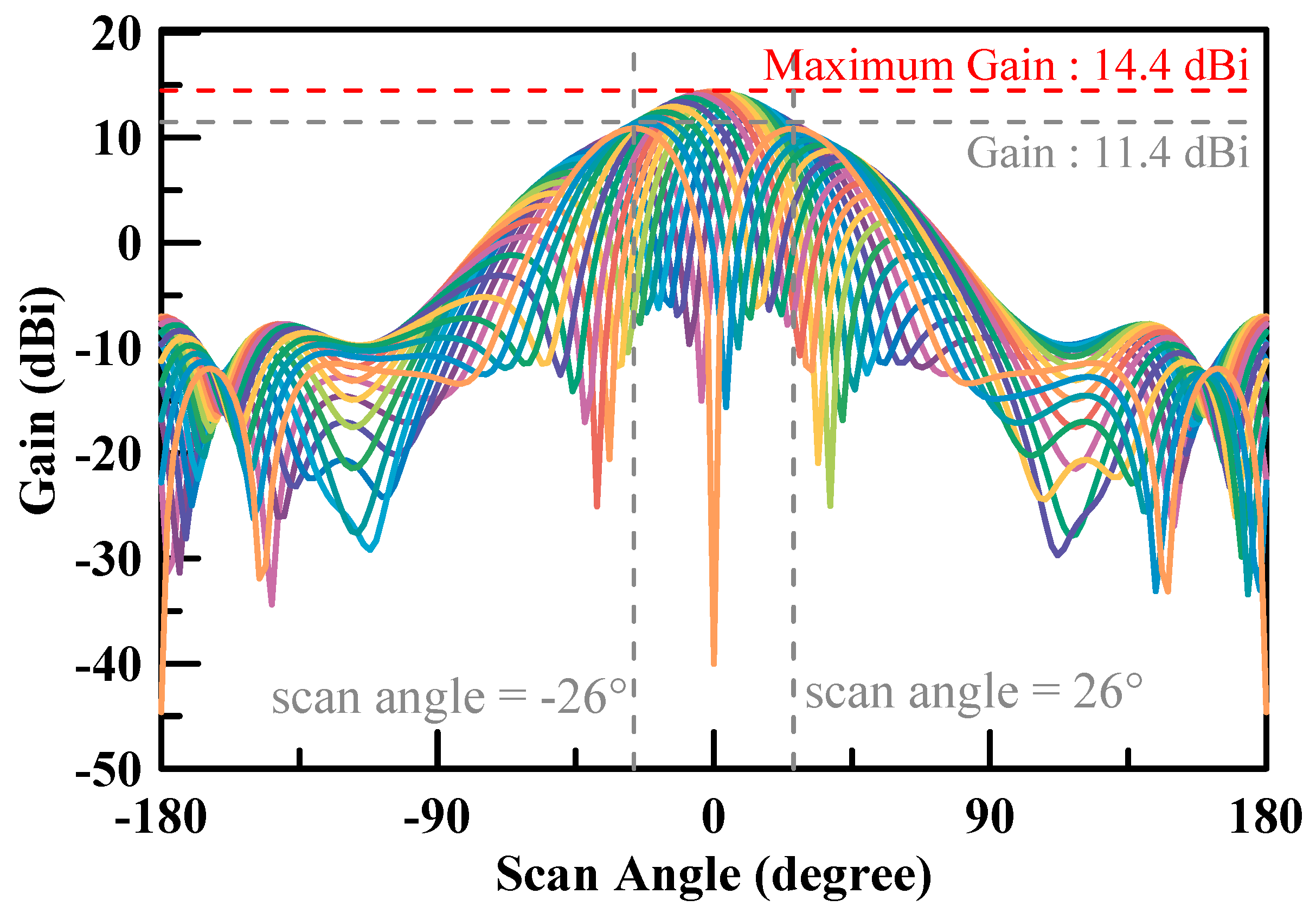
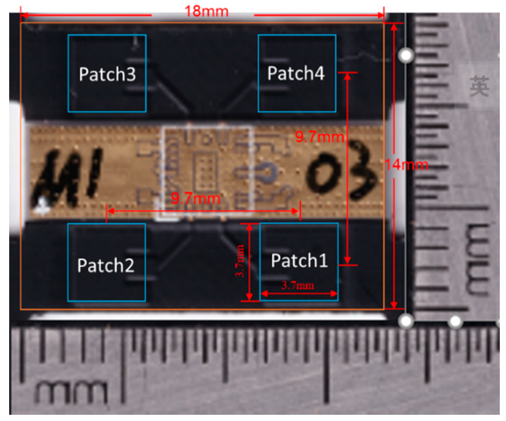
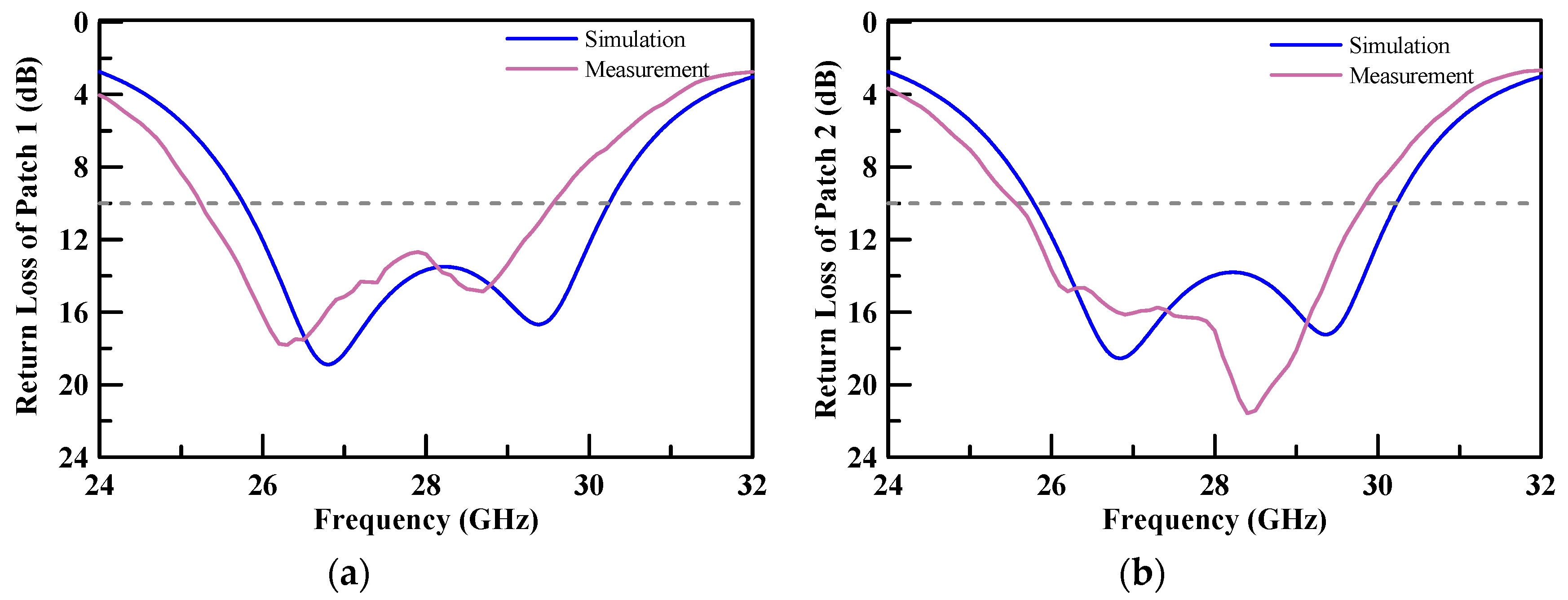
| This study | 2 × 2 | 26.5~29.5 GHz | 14.4 dB at 28 GHz | 10.6 dBi | 18 mm × 14 mm × 0.71 mm | FR4 |
© 2020 by the authors. Licensee MDPI, Basel, Switzerland. This article is an open access article distributed under the terms and conditions of the Creative Commons Attribution (CC BY) license (http://creativecommons.org/licenses/by/4.0/).
Share and Cite
Tung, W.-S.; Chiang, W.-Y.; Liu, C.-K.; Chen, C.-A.; Rao, P.-Z.; Abu, P.A.R.; Chen, W.-M.; Asadi, F.; Chen, S.-L. Low Cost AIP Design in 5G Flexible Antenna Phase Array System Application. Micromachines 2020, 11, 851. https://doi.org/10.3390/mi11090851
Tung W-S, Chiang W-Y, Liu C-K, Chen C-A, Rao P-Z, Abu PAR, Chen W-M, Asadi F, Chen S-L. Low Cost AIP Design in 5G Flexible Antenna Phase Array System Application. Micromachines. 2020; 11(9):851. https://doi.org/10.3390/mi11090851
Chicago/Turabian StyleTung, Wei-Shin, Wei-Yuan Chiang, Chih-Kai Liu, Chiung-An Chen, Pei-Zong Rao, Patricia Angela R. Abu, Wan-Ming Chen, Faisal Asadi, and Shih-Lun Chen. 2020. "Low Cost AIP Design in 5G Flexible Antenna Phase Array System Application" Micromachines 11, no. 9: 851. https://doi.org/10.3390/mi11090851