- Research
- Open access
- Published:
A flexible model for studying fringe field effect on parallel plate actuators
Journal of Electrical Systems and Information Technology volume 7, Article number: 14 (2020)
Abstract
Electrostatic parallel plate actuators are common in micro-electro-mechanical systems due to their compatibility with micro-fabrication technology. Parallel plate actuators suffer from an instability problem called the pull-in phenomenon that happens when the applied DC voltage exceeds a certain value called the static pull-in voltage. The value of this critical voltage is important in many applications that depend on parallel plate actuators such as switches and static gas sensors. The fringe field around the edges of the plates could severely affect the performance of the actuator. This paper introduces a new model for the parallel plate actuator to calculate the value of static pull-in voltage. The proposed model considers the fringe field between the two plates. The static pull-in voltage of some PolyMUMPs actuators is practically measured and compared to the simulation results that involve the fringe field effect. The model is simulated using MATLAB to show the influence of that field on the static pull-in voltage. The MATLAB results of the proposed model are validated with ANSYS.
Introduction
Electrostatic sensors and actuators are fabricated using the technology that is established for manufacturing microelectronics but with the addition of new technologies established exclusively for MEMS [1]. Additionally, they are one of the core themes of MEMS growth. The adoption of the electrostatic actuation with IC fabrication technologies is the most important reason for its commercial success. The electrostatic actuation is usually used to force defection in micro and nano-structures since the electrostatic force possesses excellent scaling characteristics in the nano- and micro-scale. Electrostatic actuators can easily be miniaturized since the electrostatic force between the two plates depends on the applied voltage, the gap distance and the plate area, but not on the plate thickness or volume. As opposed to the magnetic force which is a body force as it depends on both the area and thickness of an element, the electrostatic force is known as the surface force as it depends on the area. The fact that the electrostatic force only depends on the opposing surfaces and the distance between them, makes it well-suited for the micro-world.
The parallel plate electrostatic actuator is a major section in many electrostatic micro-systems. The parallel plate actuator has diverse applications as it’s used in switches, variable capacitors, optical fibers and ultrasonic transceivers. In several MEMS devices, elastic flexures enable relative motion between different parts of the system. These flexures are designed to have a high rigidity in all directions in which motion is to be denied, and a lower rigidity in the directions in which motion is desired. The simple capacitor is a pair of plates separated by a gap which contains an insulating material. The parallel plate actuator is a parallel plate capacitor with one movable plate and one fixed plate. Due to the opposite charges on the two plates, there is a force of attraction between the plates. In fixed-plate electrical capacitors, the electrostatic force between the two plates is not considered but it always exists whenever the capacitor is charged. Once one plate is free to move, the presence of this electrostatic force turns to be vital. Without some mechanical support providing an equal and opposite force on the upper plate, the two plates would crash on each other. The significant drawback of such actuators is the nonlinear deflection of the movable electrode within the gap which leads to the pull-in phenomenon and limits the stable travel range.
Pull-in phenomenon in electrostatic actuators is a discontinuity which occurs due to the interaction between the mechanical and electrostatic forces. The mechanical force increases linearly with the defection as opposed to the electrostatic force which grows inversely proportional to the square of the distance [2]. When the voltage is increased, the displacement increases until it reaches a certain point. Beyond this point, the electrostatic force surpasses the elastic force and the system cannot reach a balance point thus the top electrode collapses onto the bottom electrode. This point is named as pull-in limit and the critical voltage is called the pull-in voltage. The pull-in instability is an undesired effect when a large stable travel range is required as reported in [1,2,3]. However, it may be a beneficial effect when a rapid transition between two states is required. The pull-in voltage is the key regarding the design of many MEMS sensors and switches which makes calculating its value precisely a very important step in the design process of electrostatic sensors or actuators.
The main electric field which is perpendicular to the two plates is the only field considered in the most common formula to calculate the capacitance of the parallel plate actuators as in Eq. (1).
where W and L are the width and the length of plates, respectively, d stands for the separation distance, and ε is the permittivity in the gap. This formula results in a simple model of the parallel plate actuators neglecting the fringe field which is the bending of the electric flux lines near the edge of the parallel plates. However, this is not 100% precise when the gap size is comparable to the width and length of the capacitor and the exact value must be computed to calculate the pull-in voltage accurately as previously explained. The exact value of the capacitance of parallel plate actuator cannot be found in a closed-form as in Eq. (1). However, with Passion equation and proper boundary conditions, it can only be calculated by numerical methods. At certain conditions, an approximation for the value of the capacitance can be deduced [4]. Many analytical formulae have been reached to approximate the value of the capacitance considering the fringe field such as Palmer assuming zero thickness for the plates and Elliot [5]. The formula to calculate the fringing capacitance according to Palmer exhibits small error when the micro gap is large but it’s the exact same value computed by the simulation programs when the gap is very small. This formula depends on the gap width, plate width, and length as shown in Eq. (2), where A is the plate area, d is the gap distance, w is the width of the plate and L is the plate length.
On the other hand, there are plenty of formulae that consider the finite and actual thickness of the plates. Min-hang Bao Peter in [4] proposed a formula that calculates the overall capacitance \(C_{\text{overall}}\) and takes the thickness of the plates into consideration where β is a correction factor for the normal capacitance \(C_{\text{normal}}\) as in Eq. (3).
where z is the gap between the plates, w is the plate width and hp is the plate thickness. The electrostatic force value at the same voltage has now increased as the capacitance at the same voltage increased and the new value of electrostatic force is now computed as:
Meijs and Fokkema in [6] suggest another formula to calculate the fringe capacitance per unit length but also at certain conditions such as a minimum width/gap ratio of 0.3 and a maximum thickness/gap ratio of 10 to avoid large error percentage, where b, h and g are the plate width, plate thickness and the gap between the plates, respectively.
Leus and Elata in [7] compare between all the formulae that assume the zero thickness and the others that take the thickness into consideration along with their conditions. Reference [8] proposes a model to calculate the pull-in voltage of the parallel plate actuator, but they don’t consider the fringe field effect between the upper and lower plate. Reference [9] models the fringe field as a variable serial capacitor in order to consider the fringe electric field. Reference [10] considers the fringe effect and modifies the conventional equations to better estimate the capacitance and the electrostatic force of the driven structures. Consequently, there are many equations that could calculate the capacitance considering the fringe effect but each one has conditions to be able to use it such as limits on the design parameters of the actuator and the error percentage each one has when computing the total capacitance.
On the other hand, many publications have concentrated on how to simulate the value of the pull-in voltage using ANSYS software. Reference [11] compared the values of the static and dynamic pull-in voltage calculated by MATLAB simulation and ANSYS simulation with and without considering squeeze damping effect. Reference [12] used ANSYS software to simulate the single-beam and double-beam actuators. They used element (TRANS126) to model the electrostatic coupling between the beam and the ground electrode. TRANS126 element represented a conversion coupling unit that converts energy from the electrostatic field to a structural field.
Pradeep Chawda in [13] has presented a simplified equivalent circuit model for the parallel plate actuator. The actuator is modeled in the electrical domain due to the recent integration of actuators with microelectronics. The model has proved its correctness in reaching a system-level simulation for the actuator and the peripheral electronics. In addition, the model describes the dynamic behavior of the parallel plate actuator once being energized by voltage. Compared to other models of parallel plate actuators that don’t take the peripheral electronics into consideration, this model is fast and very accurate regarding the system-level simulation. It also gives an opportunity to design and optimize the performance of the complete system.
In order to overcome the instability problem of the parallel plate actuator, many control systems have been proposed. These control systems increase the stable motion of the parallel plate actuator and get benefit of most of the gap distance between the plates [14,15,16]. Reference [14] proposed a nonlinear feedback control to enhance the stable motion of the movable electrode. The nonlinear feedback control linearizes the system and hence extends the stable range of motion. This control system is great when the application of the parallel plate actuator needs most of the range between the plates as the case of driving micro-mirrors by parallel plate actuators. However, this instability issue could be a key for using the actuator as a switch that has two different states; state before the pull-in and state after pull-in. This exactly what has been done by [8] to reach a binary gas sensor benefiting from the instability issue of the parallel plate actuator.
The present work reviews the static analysis for the parallel plate actuator and introduces a new flexible model for it. The proposed model uses MATLAB Simulink to reach a precise value for that critical voltage by considering the fringe field effect. The proposed model will be tested against three different designs with different dimensions to show its effectiveness. Then, the results obtained from the proposed model will be compared with the results of a finite element tool (ANSYS software) with and without considering the fringe field. Finally, a parallel plate actuator fabricated by PolyMUMPs is practically tested and its static pull-in voltage is measured. Then, the results will be compared to the results computed by ANSYS. The actuator used in the experiment is fabricated using PolyMUMPS offered from MEMSCAP, USA, and it’s ready to be actuated by DC voltage after it has been successfully wire-bonded.
The parallel plate actuator model
The parallel plate actuator is under two forces, the electrostatic force caused by the attraction between the plates and the mechanical force caused by the cantilever as shown in the schematic in Fig. 1. The position of the upper plate is determined by the net force between the electrostatic and mechanical forces. The equation of the actuator in standard form as a second-order system is
where m is the mass of the movable plate, b is the squeeze damping coefficient,\(x\) is the displacement of the movable plate, k is the cantilever stiffness and Fe is the electrostatic force. Regarding the static condition, both \(\ddot{x}\) and \(\dot{x}\) are equal to zero. Then the static pull-in voltage of the parallel plate actuator without the fringe effect is calculated by Eq. (7) [4], where d is the gap distance, k is the stiffness and A is the plate area.

The schematic of the parallel plate actuator
A mathematical model is proposed in [8] in which the displacement at any DC applied voltage could be easily calculated. Assuming the applied voltage is DC voltage, the displacement of the plate is
where x is the movable plate displacement, Lc is the ratio between the distance from the cantilever’s end to the center of mass of the plate and the cantilever length, d is the initial gap of the actuator and A and B are constants calculated at each voltage value by solving the nonlinear Eqs. (9) and (10)
where α and Mp are constants and calculated as shown in Eqs. (11) and (12) and V is the applied voltage.
where bp is the plate width, L is the cantilever length, E is Young’s modulus, I is the moment of area, d is the initial gap, mp is the plate mass and g is the gravity force. A and B then could be calculated at any voltage and the corresponding displacement is calculated by Eq. (8). Using this model, the static pull-in voltage considering the total stiffness of the cantilever could be easily computed along with the value of the total stiffness at any applied voltage.
The proposed model
The proposed model shown in Fig. 2 is defined by Eq. (6). The model calculates the electrostatic force Fe based on calculating the additional fringe capacitance in addition to the normal one. Calculating the capacitance of the parallel plate actuators is a vital step in designing MEMS. The main electric field which is perpendicular to the two electrodes is the only field considered in the most common formula to calculate the capacitance of the parallel plate actuators. However, this formula results in a simple model of the parallel plate capacitor since the effect of the fringe field is neglected. Meanwhile, this fringing field adds value to the total capacitance and in case of MEMS parallel plate actuator; it also boosts the value of electrostatic force.

Parallel plate actuator Simulink model
According to the equations in Sect. 1, it’s clear that each equation that calculates the total capacitance has its own limits to reduce the error of the result. These limits should be considered and compared to the dimensions of the actuator to decide which one will be used to calculate the pull-in voltage considering fringe field and here comes the advantage of the proposed model. The proposed model as shown in Fig. 2 has a part called “Electrostatic Force Calculation”. In that part, any equation from the above equations could be used to calculate the total capacitance depending on the dimensions of the actuator. Consequently, whatever the dimensions of the actuator are, the proposed model could be used to calculate the static pull-in voltage precisely including fringe field capacitance.
Simulation results
In this section, actuator ‘1’ in Table 1 will be analyzed step by step until the final and actual pull-in voltage is reached. The new model here applies Eq. (5) to calculate the fringe field capacitance since the dimensions of the actuator understudy match the constraints stated above. Then, the results are verified by ANSYS with and without considering the fringe field. The dimensions are listed in Table 1 in µm. These actuators are made of poly-silicon whose Young’s modulus is 160 GPa and its density is 2300 kg/m3.
-
1.
The static pull-in voltage is calculated using MATLAB Simulink. Figure 3 describes the dynamic behavior of the actuator at different voltages. The pull-in voltage value computed by this Simulink matches the one calculated by Eq. (7) which is 9.62 volts. The actuator’s stiffness in this step is calculated by Eq. (13), where E is Young’s modulus, b is the width of the cantilever, h is the cantilever’s thickness and L is the length of the cantilever.
$$k = \frac{{E b h^{3} }}{{4 L^{3} }}$$(13)Fig. 3 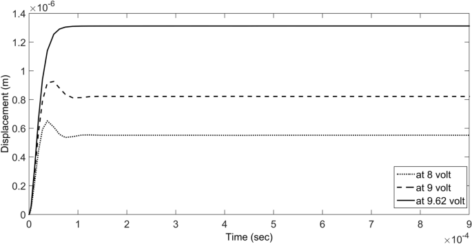
Actuator behavior at different voltages
-
2.
The model in [8] considers the electrostatic stiffness which has not been accounted in the static analysis. This model is applied and the displacement of the moving plate (x) is calculated at every voltage (V). Also, the static pull-in voltage is calculated.
-
3.
The fringe field effect is considered in the proposed model and calculated using Eq. (5). In addition, the total stiffness at all the applied voltages is calculated using Eq. (6) where both \(\ddot{x}\) and \(\dot{x}\) are equal to zero and substituting with the value of the electrostatic force. Thus, the total stiffness which takes the electrostatic stiffness into consideration is calculated as in Eq. (14), where A is the plate area, V is the applied voltage, x is the displacement of the movable plate and d is the initial distance between the movable and fixed plate.
$${\text{k}} = \frac{{\varepsilon_{o} \varepsilon_{r} A V^{2} }}{{2 x \left( {d - x} \right)^{2} }}$$(14)

Then in this model, the stiffness is changed to the corresponding voltage value. Figure 4 shows the electrostatic force at the same voltage (8.18 volts) but with and without considering the fringe field. It’s noted that despite both forces are calculated at the same voltage but the model that considers the fringe effect expresses higher capacitance and consequently higher electrostatic force. This is the reason why the pull-in voltage is lower than that calculated by [8] because the moving plate is now reaching the same point but with lower voltage.

Force at 8.18 V with and without considering fringe effect
Then, the actuator is simulated by ANSYS with and without considering the fringe field and the value of pull-in voltage is compared to the values of the model reported in [8] and the proposed model. In ANSYS, the element of the actuator’s structure is SOLID186 and the gap between the plates used SOLID226 as the coupling field element. SOLID123 tetrahedral element models the air surrounding the actuator by extending that element beyond the boundaries of the actuator to simulate the effect of the fringe field. Table 2 summarizes the results obtained from the proposed model, the model in [8] and ANSYS for actuator ‘1′.
Table 3 shows the pull-in voltage with and without considering the fringe effect for the three actuators in Table 1. In addition, the value of capacitance at the same voltage with and without considering the fringe field is shown in Table 4.
Experimental results
In this section, the pull-in voltage of a parallel plate actuator is tested. The actuator consists of two plates and the upper plate is linked to two separated beams at the far end of the upper plate to increase the torsional stiffness. The chip is fabricated by PolyMUMPs and the actuator is wire-bonded and ready to be actuated by DC voltage. The actuator is shown in Fig. 5 and the designed dimensions for the actuator are shown in Table 5 in µm.

The actuator under the microscope of the probe station
The cantilevers and the upper plate are made of layer “Poly2″ and the ground is made of layer “Poly0″. These designed dimensions are the same sent by [8] and yet they are not the real dimensions. [8] used an optical profiling system to measure the real in-plane dimensions of the actuator, and they were found different compared to the designed dimensions. The real dimensions are listed in Table 6 in µm except for the thickness of the plate and cantilevers which cannot be measured by the optical profiling system.
The actuator is actuated by DC voltage and the circuit in Fig. 6 detects the pull-in of the actuator. As long as the pull-in did not occur, the voltage at the gate of the MOSFET would be zero so the LED is off. Once the movable plate touches the fixed one, the voltage at the gate of MOSFET starts to increase and the LED is on. It’s noticed that the illumination of the LED increases gradually and this may happen due to the increase of the contact area. As the area of contact increases, the resistance of contact decreases which in turn increases the illumination of the LED gradually. A 1 µF capacitor is placed before the MOSFET to suppress any noise that could be caught by the 1.76 GΩ resistance. A step of 10 mV is used and after each step, the detection circuit is monitored for 3 min to assure that the pull-in didn’t occur. The measured pull-in voltage according to the detection circuit is 8.19 volts.

Pull-in detection circuit
If the thickness of the plate and cantilevers is 1.5 µm and the dimensions are the same in Table 6, the pull-in voltage value according to the proposed model and ANSYS software with considering the fringe field should be 9.94 volts, not 8.19 volts. Consequently, the actual thickness of the plate and cantilevers is also not 1.5 µm as in the designed dimensions and the exact value is unknown. According to [17], the thickness of the structural layer “Poly2″, which is the layer of the plate and cantilevers, ranges from 1.4 µm to 1.6 µm and the minimum Young’s Modulus is 148 GPa. This range will be the accuracy criteria for the proposed model. The dimensions in Table 6 will be simulated by ANSYS and the proposed model with different values for the thickness to check which model will give a thickness closer to the range when the pull-in occurs. In other words, many thicknesses will be used on the proposed model to see which thickness will give the measured pull-in voltage (8.19 volts). The same will be done in the ANSYS model and then the results will be compared. The model which will give a thickness closer to the range will be the more accurate model.
Figure 7 and Table 7 compare the measured pull-in voltage value and the values of thickness computed by the proposed model and ANSYS software in µm. As indicated in Fig. 7, the ANSYS simulation without considering the fringe field gives a value of 1.31 µm for the thickness to reach the measured pull-in voltage. However, the proposed model gives a value of 1.32 µm for the thickness. In other words, the thickness that matches the measured pull-in voltage value with the simulated value is 1.32 µm and 1.31 µm according to the proposed model and ANSYS simulation respectively.

Comparison between ANSYS software and proposed model results
In addition, the calculations have been repeated at the minimum possible Young’s Modulus (148 GPa) and the results are summarized in Table 8. It’s noted that the proposed model also gives a thickness closer to the range when considering the fringe field effect.
Discussion
The new proposed model calculates the pull-in voltage precisely as it takes into consideration all the factors that influence the pull-in voltage. Any formula that can calculate the total capacitance including the fringe field can be implemented which means that there are no longer constraints about the actuator dimensions. The simulation results of studying actuator 1 shown in Table 2 show that the value of the pull-in voltage without considering the fringe field effect is the same for the proposed model and the model in [8]. In addition, they agree with the result of ANSYS. However, when the fringe field is considered, the value drops to a new value. The result that considers the fringe effect proves that the fringe field that is generated around the edges of the plate influences the actuator performance.
In addition, two other actuators with different dimensions are simulated in Table 3 to confirm these results. It’s noticeable that the fringe field boosts the capacitance value when it’s considered as shown in Table 4. Neglecting the fringe field effect would result in an erroneously calculated value of the pull-in voltage. In addition, when the gap length is comparable to the plate length and width, the effect of the fringe field on the capacitance increases. This is the reason why the percentage increase of capacitance in actuator ‘1’ is higher than actuator ‘3’.
For the practically characterized actuator, taking into consideration the measured pull-in voltage and the tolerance in the poly-silicon layer thickness (Poly2), the proposed model is compared to the model in [8] and ANSYS. The result of the proposed model, according to Table 7, is closer to the range given by the foundry itself. In other words, the computed thickness of the actuator by the proposed model is closer to the range given by PolyMUMPs itself and it’s more precise in calculating the pull-in voltage. This small variation in the pull-in voltage may severely influence the actuator performance if the actuator is working near the critical region just before the pull-in limit like in case of switching. The actuator working near the pull-in limit expresses higher sensitivity which gives it an advantage when it’s used as a binary gas sensor. When the actuator is used as a gas sensor as in [8], the erroneous value affects seriously the operation of the sensor since its main operation is near the pull-in limit. Thus, the fringe effect should be considered when the parallel plate actuator works as a gas sensor if a minimum captured mass is desired.
Conclusion
A new flexible model has been introduced for the parallel plate actuator. It takes into consideration the fringe field effect which reduces the value of pull-in voltage due to the added capacitance. Thus, it highly affects the performance of the parallel actuator especially when it’s working near the pull-in voltage. The model can implement any formula that calculates the total capacitance including the fringe field. The results of the proposed model are validated by ANSYS.
Availability of data and materials
All the data are included in the manuscript’s tables.
Abbreviations
- MEMS:
-
micro-electro-mechanical systems
- PolyMUMPs:
-
poly multi-user MEMS processes
- ANSYS:
-
analysis system
References
Conrad H, Kaiser B, Gaudet M, Langa S, Stolz M, Uhlig S, Schimmanz K, Schenk H (2016) A novel electrostatic actuator class. Procedia Eng 168:1533–1536
Nabian A et al (2006) Investigation of pull-in phenomenon of rectangular micro-plate subjected to nonlinear electrostatic pressure. Sens Transducers J 73(11):810–818
Zhang W-M, Yan H, Peng Z-K, Meng G (2014) Electrostatic pull-in instability in MEMS/NEMS: a review. Sens Actuat A 214:187–218
Bao M (2005) Analysis and design principles of MEMS devices. Elsevier, Amsterdam
Hosseini M, Zhu G, Peter (2007) A new model of fringing capacitance and its application to the control of parallel-plate electrostatic micro actuators. arXiv preprint arXiv:0711.3335
Chuang W-C, Wang C-W, Chu W-C, Chang P-Z, Yuh-Chung H (2012) The fringe capacitance formula of microstructures. J Micromech Microeng 22(2):025015
Leus V, Elata D (2004) Fringing field effect in electrostatic actuators. Technion-Israel Institute of Technology Technical Report No. ETR-2004-2
Khater ME, Al-Ghamdi M, Park S, Stewart KME, Abdel-Rahman EM, Penlidis A, Nayfeh AH, Abdel-Aziz AKS, Basha M (2014) Binary MEMS gas sensors. J Micromech Microeng 24(6):065007
Hosseini M, Zhu G, Peter Y-A (2007) A new formulation of fringing capacitance and its application to the control of parallel-plate electrostatic micro actuators. Analog Integr Circ Sig Process 53(2–3):119–128
Fang D, Zheng F, Bo Chen Yu, Wang YF, Yang P, Wen X, Peng C, Xia S (2015) Computation of capacitance and electrostatic forces for the electrostatically driving actuators considering fringe effects. Microsyst Technol 21(10):2089–2096
Liu X et al (2019) Simulation of Pull-in mechanism of plate actuator considering damping. J Phys: Conf Ser 1303(1):1
Ouakad HM, Muhammad AH, Al-Qahtani HM (2013) Modeling the electrostatic deflection of a MEMS multilayers-based actuator. Math Problems Eng 2013:1
Chawda P (2017) A Simplified Equivalent Circuit Model of MEMS Electrostatic Actuator. Int J Comput Appl 160(9):1
Li C et al (2014) Nonlinear feedback control to enhance stable performance of micromachined electrostatic parallel plate actuators. Int J Autom Power Eng 3(1):49–52
Dong L, Jason E (2010) Closed-loop voltage control of a parallel-plate MEMS electrostatic actuator. In: Proceedings of the 2010 American Control Conference. IEEE
Moreira EE et al (2016) Low-voltage, high-tuning range MEMS variable capacitor using closed-loop control. Procedia Engineering 168:1551–1554
Cowen A, Hardy B, Mahadevan R, Wilcenski S (2011) PolyMUMPs design handbook revision 13.0. MEMSCAP Inc
Acknowledgements
Authors like to express their gratitude to the “Academy of Scientific Research & Technology” in Egypt for granting them a chance to be a part in one of their projects in the DLMEI alliance. Authors would like to express their deep appreciation to Professor Eihab Abdel-Rahman (University of Waterloo, Canada) for his guidance and help throughout this work. Authors are very grateful to Dr. Majed S. Alghamdi for his time and patience. Also, authors would like to thank Dr. Sangtak Park for his help with the detection circuit.
Funding
The authors declare that they did not receive any funding for this research.
Author information
Authors and Affiliations
Contributions
All authors have read and approved the manuscript. AE made the experimental work with the help of ME. MS helped AE with the basics of the experiment and how to combine the setup and how to simulate the experiment on ANSYS software. EE and AA helped AE with writing the paper to make it academically appropriate. All authors read and approved the final manuscript.
Corresponding author
Ethics declarations
Competing interests
The authors of the current study declare that they have no conflict of interest.
Additional information
Publisher's Note
Springer Nature remains neutral with regard to jurisdictional claims in published maps and institutional affiliations.
Rights and permissions
Open Access This article is licensed under a Creative Commons Attribution 4.0 International License, which permits use, sharing, adaptation, distribution and reproduction in any medium or format, as long as you give appropriate credit to the original author(s) and the source, provide a link to the Creative Commons licence, and indicate if changes were made. The images or other third party material in this article are included in the article's Creative Commons licence, unless indicated otherwise in a credit line to the material. If material is not included in the article's Creative Commons licence and your intended use is not permitted by statutory regulation or exceeds the permitted use, you will need to obtain permission directly from the copyright holder. To view a copy of this licence, visit http://creativecommons.org/licenses/by/4.0/.
About this article

Cite this article
Elshenety, A., El-Kholy, E.E., Abdou, A.F. et al. A flexible model for studying fringe field effect on parallel plate actuators. Journal of Electrical Systems and Inf Technol 7, 14 (2020). https://doi.org/10.1186/s43067-020-00022-7
Received:
Accepted:
Published:
DOI: https://doi.org/10.1186/s43067-020-00022-7