

Abstract
The total scattering cross section (or width) of strongly scattering metallic objects can be reduced by using various cloaks, which are complex structures with a limited frequency bandwidth. In many applications, however, dramatic reduction of total scattering is not always required, for instance, when backscattering reduction is the critical parameter. Moreover, the direction of illumination is sometimes known and scattering reduction for other illumination directions is not required. In these scenarios, it is possible to achieve the desired scattering reduction using much simpler manufactured devices. In this paper, we explore possibilities to reduce backscattering and forward scattering from cylindrical bodies for plane-wave illumination from a certain direction. The proposed scattering-reduction device is a shell formed by several sectors of different uniform dielectric materials. We compare the requirements on the material cover which are needed to reduce backscattering and forward scattering widths and outline the corresponding design approaches. We show that all-dielectric and easily realizable structures can effectively reduce total scattering without using active materials or non-uniform anisotropic materials. We develop and numerically test the method for TE-polarized incident waves, since this polarization is more critical for considered applications.
Export citation and abstract BibTeX RIS
1. Introduction
Reduction of back or total scattering from impenetrable, usually metallic, bodies is necessary in a number of application such as the minimisation of parasitic scattering from struts of large reflector antennas [1] or support structures near air-field radars. Another application is the reduction of electromagnetic interference and antenna blockage, between closely located antennas [2–4]. In this paper, we will consider the reduction of scattering from metallic ducts which are used to confine the cables inside antenna radomes of sea vessels. These ducts are often found in the radiation path of antennas causing backward reflections towards the source, creating shadow zones due to forward scattering, and also worsening of the radiation pattern of other nearby antennas. The objectives on scattering reduction depend on the characteristics of the application. For example, reduction of backscattering is important for maintaining antenna matching and protecting sensitive receivers. However, reduction of total scattering, defined as the integrated Poynting vector of the scattered fields around the cylinder, is useful for camouflaging and low observability.
Due to the simplicity and low cost of the fabrication process, the ducts typically have circular-cylinder geometry. A good approximation to study the scattering properties of the ducts is to consider them as infinite metallic cylinders, as shown in figure 1. The described geometry produces strong scattering when the the electric field of the incident wave is polarized along the cylinder axis (TE-polarized incidence), so in this work we will be only focused on this polarization. Scattering from infinite cylindrical bodies is characterized by the equivalent scattering width that, assuming TE-polarization, is defined as [5]:
Here,  and
and  are the complex amplitudes of the scattered cylindrical wave and the incident plane wave, respectively and ρ is the distance to the observation point from the axis of the cylinder. The parameter σ depends on the direction to the observation point, which we characterize by the polar angle φ, measured from the direction of the x axis (figure 1). This parameter is important if the goal is to minimize scattering towards a specific direction or directions. In particular, the value of σ at φ = 0 corresponds to the backscattering width. Another important parameter is the total scattering width defined as [5]:
Minimization of this parameter corresponds to hiding the object completely, that is, to cloaking.
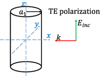
Figure 1. Illustration of an infinite cylinder illuminated by TE-polarized electromagnetic plane wave.
Download figure:
Standard image High-resolution imageThese two parameters are related by the optical theorem, which states that the sum of the total scattering width and the absorption width  (called extinction width) is proportional to the amplitude of the forward-scattered cylindrical wave (e.g. [5]):
Here, the scattering amplitude F is defined by writing the expression for the field of the scattered cylindrical wave as [5],
(k is the wavenumber in surrounding space). For lossless cylinders  and we see that minimization of the forward scattering width is tantamount to minimization of total scattering.
The optical theorem (3) tells us that scattering from a cylinder can be totally eliminated only if the absorption width  is zero. This means that the cylinder cover (we consider reduction of scattering from perfectly conducting (PEC) cylinders) must be lossless or contain gain materials or inclusions to compensate loss. This task of reducing total scattering width corresponds to cloaking, which can be passive (lossless) [6–11] or active [12, 13]. Back- and side-scattering (towards a specific direction) can be reduced using passive, absorbing coatings [14–17]. For the case of active coatings, the optical theorem does not apply, and it is possible to design an optimized homogeneous active material coating, which will reduce forward scattering [18] without necessarily reducing back and total scattering widths.
Besides the design goal (minimizing total or backward scattering), the choice of an appropriate technical solution depends on the electrical diameter of the cylinder. For example, if the goal is to minimize backscattering width of an electrically thick cylinder, the use of thin absorbing coatings is appropriate. If the illumination direction is known, it is enough to cover only the front face with an absorbing strip of the width of the order of the wavelength (while the cylinder diameter can be electrically large). Alternatively and if the application allows, it is possible to properly change the shape of the cylinder cross section to avoid the existence of a stationary point at the front face [5] and, additionally, use hard-surface covers [1]. If the cylinder diameter is electrically small, arguably the most appropriate technique is the scattering-cancellation cloaking [19, 20], in particular, mantle cloaks [21]. In this technique, the scattering of an object can be mitigated by adding to the system another object, the scattering of which is complementary with respect to the principal scatterer. The scattering-cancellation approach requires that the cover is conformal to the object and has exotic material parameters such as near-zero permittivity. The coordinate transformation technique [22, 23], in which the creation of a volume, where electromagnetic fields do not exist, can also be in principle implemented to reduce total scattering. Total scattering reduction based on the coordinate transformation technique also requires realization of exotic materials with suitable properties, with permittivity and permeability less than unity, and the scattering reduction takes place in extremely narrow frequency bands. The transmission-line cloak technique [10] is also a possible method used for total scattering reduction. This technique is based on the use 2D or 3D transmission-line networks. In these structures, the electromagnetic fields propagate inside transmission lines, thus leaving the volume between these lines effectively cloaked, but the cloaks have comparably large sizes.
In this work, we focus on the intermediate case of cylinders whose diameter is of the order of the wavelength, which is usually the case with metallic ducts near antenna structures of sea vessels. From the practical point of view, it is desirable that the scattering-reducing cover would be simple and easily realizable in practice [24]. Recently, active cloaks which consist of an inhomogeneous coating made of a balanced loss (passive) and gain (active) materials have been proposed [12], but active material covers are difficult to implement [13]. Furthermore, they require complicated, angularly inhomogeneous covers. Also, these devices suffer from possible instabilities. Our aim is to show that, by using well-customized simple passive coatings, it is possible to effectively reduce back and total scattering widths. In particular, we consider coverings realized as piece-wise homogeneous material layers. The permittivity of each sector can be properly chosen and optimized in order to reduce scattering for a specified range of scattering angles. This approach is motivated by the fact that there is a possibility to realize effective compromise solutions where absorbing coatings are used only where they are effective in reducing backscattering. In this case, in other areas around the cylinder, low-loss covers can be used to shape scattering in other directions, including the forward direction.
We start from reviewing the classical problem of bistatic scattering width of a perfectly conducting cylinder coated by a uniform dielectric layer and select a homogeneous dielectric coating for reducing scattering in a given direction. For completeness of the study, one passive coat for backscattering reduction and one active coat for forward scattering reduction are presented as examples. We show that for both cases, either the backscattering or forward scattering width is not reduced. Next we consider inhomogeneous, sector-wise uniform coatings using optimized sectors for two different application scenarios. In one of the cases (scenario 2), the backscattering width is almost zero, the forward scattering width is reduced by 78% and the total scattering is reduced by 65% at the optimization frequency (3 GHz). With the two scenarios of inhomogeneous coatings, the back, forward, and total scattering widths can be effectively reduced in the whole range of 1–3 GHz. In all the considered cases, PEC cylinders having the radius equal to  (
( is the free-space wavelength at 3 GHz) are considered. Also, all considered coatings have the thickness of
  . For simplicity and in view of targeted applications, we consider only illuminations by TE-polarized plane waves at 3 GHz and assume that coatings are non-magnetic.
2. Reduction of scattering from PEC cylinders using homogeneous coatings
Let us consider an electrically long and PEC cylinder of radius a1, illuminated by a plane electromagnetic wave at normal incidence, as illustrated in figure 1. The bistatic scattering width 1 of an infinite PEC cylinder under normal incidence is given by (e.g. [5]):
where φ is the scattering angle, measured from the direction of the axis x, Jn is the Bessel function, and  is the Hankel function of the second kind. Furthermore, κ = 1 for TE-polarized waves. It can be seen from equation (5) that the scattering width of PEC cylinders strongly depends on the cylinder radius. Generally, the larger the radius, the stronger the total scattering. As discussed in the introduction, in order to reduce backscattering as well as scattering in specific side directions, passive (lossy) material coatings can be used, while forward scattering can be eliminated using only lossless covers. If the cover is uniform, such forward scattering reducing coating should be active. The permittivities of homogeneous coatings for scattering reduction can be calculated as follows.
Let us consider a PEC cylinder coated with a homogeneous dielectric layer of thickness h, having the relative permittivity  illuminated by an TE-polarized plane wave, as illustrated in figure 2. Here, ɛ0 is the permittivity of the surrounding space (assumed to be free space in our case).
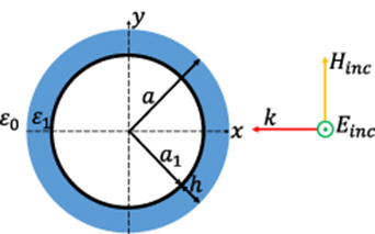
Figure 2. PEC cylinder of radius a1 coated by a dielectric layer of thickness h, illuminated by an TE-polarized plane wave.
Download figure:
Standard image High-resolution imageOne way of reducing scattering is to fix the thickness of the dielectric layer and find the effective permittivity of the latter which corresponds to the minimum scattering at a given scattering angle. By using equations (A1)–(A9) given in the appendix, the radius of the PEC cylinder, a1, the thickness of the dielectric, h, the incidence angle, ψ, and the scattering angle, φ, can be fixed, while  and
and  can be varied in order to find the effective permittivity of dielectric that corresponds to minimized scattering in a given direction. As an example, figure 3 shows a colormap illustrating the values of the real part of the permittivity
  and its imaginary part
  that provide the smallest possible backward scattering (φ = 0°) and forward scattering (φ = ±180°) from a cylinder having a1 = λ/2 radius covered by an h = λ/5 coating when it is normally illuminated by a TE-polarized plane wave.
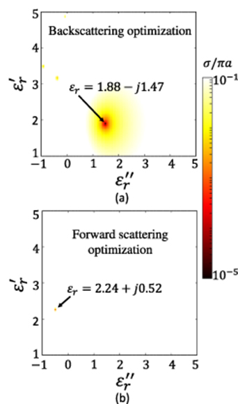
Figure 3. Colormap of the normalized: (a) back and (b) forward scattering widths, for finding the optimal real and imaginary parts of the permittivity of a λ/5 thick coating of a cylinder having λ/2 radius.
Download figure:
Standard image High-resolution imageWe can see from figure 3(a) that the optimal coating should be passive ( with
with  ) and very lossy in order to reduce backward scattering and must be active (
 with
with  ), as shown in from figure 3(b), for forward scattering reduction. The scattering width values presented throughout this paper are normalized by dividing by πa, where a is the radius of the coated cylinder (a = a1 for non-coated cylinders). The bistatic scattering width for homogeneous coatings optimized for the reduction of back- and forward scattering widths are calculated using equations (A1)–(A9) in the appendix and simulated using COMSOL Multiphysics. The scattered electric fields are also illustrated in figure 4.
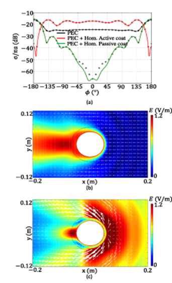
Figure 4. (a) Calculated (markers) and simulated (continuous curves) normalized bistatic scattering widths of a PEC cylinder are shown in black, of a PEC cylinder coated by a homogeneous dielectric optimized to reduce the backward scattering (ɛr = 1.88 − j1.47) are in green, and a PEC cylinder coated by homogeneous dielectric optimized to reduce forward scattering (ɛr = 2.24 + j0.52) are plotted in red. (b) Magnitude of the scattered E-fields for a PEC cylinder coated by a homogeneous dielectric layer optimized to reduce backscattering. (c) Magnitude of the scattered E-fields for PEC cylinder coated by a homogeneous dielectric layer optimized to reduce forward scattering. The Poynting vectors represented in (b) and (c) denote the vector direction of the total field. The incident wave propagates from the right to the left.
Download figure:
Standard image High-resolution imageAnalysing figure 4, we see that the normalized backscattering width of the uncoated PEC cylinder is of the order of −24 dB. The normalized forward scattering width in this case is −16 dB. When the cylinder is coated with a passive layer (the green curve), the normalized backscattering width is reduced to below −60 dB. The normalized forward scattering width, however, slightly increases compared to the non-coated PEC cylinder (the black curve). When the cylinder is coated with an active layer (the red curve), the normalized forward scattering width is reduced and is below −30 dB, but the normalized backscattering width increases as compared to the uncoated PEC cylinder.
Since we are interested in optimizing three positive quantities ( ,
,  and
and  ), in order to compare the results of different optimizations, data can be represented in the form of a bar chart as illustrated in figure 5. For the bar chart representation, the scattering produced by the coated PEC cylinders are normalized by the scattering produced by the uncoated cylinder. Interesting cases of coating are those for which the normalized back (
 ), forward (
 ) and total scattering (
 ) is less than one. The closer these three parameters will be to zero, the closer the coating will be to a perfect cloak. It must be noted that the y-axis of the bar chart has been put in log-scale for better representation of near zero values.
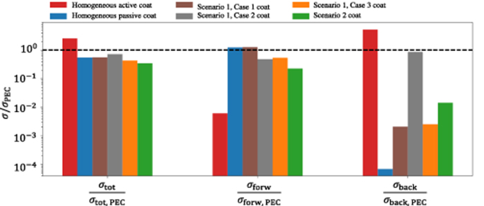
Figure 5. Normalized total ( ), forward (
 ) and back (
 ) scattering produced by a PEC cylinder coated with different coatings. The y-axis has been represented in logarithmic scale.
Download figure:
Standard image High-resolution imageThe illustration of figure 5 confirms our previous observations. Using a homogeneous dielectric optimized for backscattering reduction (blue bar) reduces the back and total scattering widths but the forward scattering is increased in this case. When an active homogeneous dielectric optimized for forward-reduction (red bar) is coated around the PEC cylinder, the forward scattering is reduced but the back and total scattering widths are increased. These results indicate that one single homogeneous passive dielectric layer optimized for reduction of backscattering or one homogeneous active dielectric optimized for reduction of forward scattering are not enough to ensure reduction of total scattering by metal cylinders having the radius comparable to the wavelength. For both coatings, either a shadow zone or a strong backward scattering is observed. Two optimized sectors (one passive for backscattering reduction and one active for forward scattering reduction) can be used to reduce the total scattering, as in active, PT-symmetric cloaks [12], but this is a solution which is difficult to realize in practice.
For this reason, next we consider the possibility to use sector-wise homogeneous coatings, so that lossy materials can be used only in the sectors where losses help to reduce scattering. We will study the performance of several optimized passive sectors (sector-wise inhomogeneous coatings) for reduction of back, forward (and, consequently, total) scattering widths.
3. Inhomogeneous, sectorial coatings
3.1. Scenario 1: Four sectors
The first scenario of inhomogeneous coating presented in this article for the reduction of  ,
,  and
and  of a PEC cylinder whose radius is comparable to the wavelength is to use four sectors as illustrated in figure 6. Sector 1 is filled with a dielectric having relative permittivity ɛr1, sectors 2 are filled with dielectrics having relative permittivity ɛr2, and sector 3 is a dielectric layer having relative permittivity ɛr3. The thicknesses of all sectors have been fixed to h = λ/5.
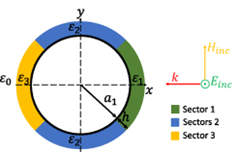
Figure 6. PEC cylinder having radius a1 = λ/2 coated by four sectors of dielectric coatings having the thickness h = λ/5, illuminated by an E-polarized plane wave.
Download figure:
Standard image High-resolution imageThe permittivity of sector 1 is optimized using equations (A1)–(A9) of the appendix assuming a homogeneous cylinder for minimization of backscattering (φ = 0°). The permittivities of sectors 2 are also optimized using equations (A1)–(A9) assuming a homogeneous coating for optimization of side scattering (φ = 90° and φ = −90°). For the cylinder being mirror symmetric with respect to the plane formed by k and Einc, sectors 2 have the same properties. For a PEC cylinder of radius a1 = λ/2 and the coating thickness of h = λ/5, the homogeneous dielectric cover optimized for backscattering reduction has the calculated permittivity of ɛr1 = 1.88 − j1.47, the homogeneous dielectric optimized for the side scattering reduction has the calculated permittivity of ɛr2 = 2.11 − j1.08. As we discussed in the previous section, the best uniform cover for forward scattering reduction is active, with the permittivity ɛr = 2.24 + j0.52. Based on this result, we fill sector 3 with a lossless dielectric having the same permittivity as the real part of that value: ɛr3 = 2.24 − j0. Three different cases are studied for this scenario. The corresponding permittivities of the sectors are given in table 1.
Table 1. Different cases of interest for the 4-sector coating.
| Case | Sector 1 | Sectors 2 | Sector 3 |
|---|---|---|---|
| 1 | 1.88 − j1.47 | 2.11 − j1.08 | 2.24 − j0 |
| 2 | 1.88 − j0 | 2.11 − j0 | 2.24 − j0 |
| 3 | 1.88 − j1.23 | 2.11 − j0 | 2.24 − j0 |
Case 1 corresponds to the values of optimal permittivities of sectors calculated for homogeneous coatings for reduction of back, side and forward scattering. Sectors 1 and 2 are rather lossy in this case. All sectors are lossless for case 2 and only sector 1 is allowed to have some losses in case 3. The corresponding scattering widths for the four cases are presented in figure 7.

Figure 7. Bistatic scattering by a PEC cylinder having radius λ/2 (black) for the three different coatings.
Download figure:
Standard image High-resolution imageIt can be seen from figure 7 that when sectors 1 and 2 are lossy (red curve), the backscattering width is reduced but, as expected, the forward scattering is stronger than the forward scattering by the uncoated PEC cylinder. When sectors 1 and 2 are lossless (blue curve), the forward scattering width is reduced, but the backscattering width ripples around the backscattering level for the PEC cylinder. Figure 5 compares the normalized back, forward and total scattering widths for the three cases under study.
One important case is when only sector 1 has some losses and the other sectors are lossless (case 3, denoted by the orange bars in figure 5). In this case, the normalized total and forward scattering widths are less than one and the backscattering width is very close to zero. Compared to the homogeneous coating optimized to reduce backscattering (blue bar), the normalized total scattering width is reduced by 23% and the forward scattering width is reduced by 56%. The backscattering width remains close to zero as for the homogeneous lossy coating. Without using active materials, a very good reduction of back, forward, and total scattering has been achieved.
Finally, let us compare case 1 (losses in sector s1 and 2) and case 3 (only sector 1 is lossy). We can see that, even though losses in sectors 2 produce a small reduction in backscattering, the reduction of total and forward scattering is compromised in case 1. From this comparison, it seems that making only the front-facing sector optimized for backscattering reduction lossy and rather small in length, forward scattering can be significantly reduced. In the next example, we explore this possibility with the design of a 16-sector coating. The validity of the numerical results presented in this article has been verified using CST Studio 2016. A good agreement between COMSOL Multiphysics and CST Studio 2016 results has been observed.
3.2. Scenario 2: Numerically optimized 16 sectors
Here, we present the results of a coating split into 16 sectors and optimized using COMSOL Multiphysics in-built optimization tool, with the objective to obtain the minimum possible forward scattering. The parameters that were allowed to be modified by the optimization tool were the permittivities of the sectors. The initial values were defined by the method that we used in scenario 1. During the optimization process, the real parts of the permittivity of all of the sectors were allowed to be optimized in the range of 1−10 and the dielectric losses (tan  ) were allowed to be optimized in the range of 0 − 1.5. Only sector 9, designed to reduce forward scattering reduction, was fixed to be lossless. We then observed and analyzed the set of permittivity values obtained for the different sectors. For example, if one set of permittivity combination provided the low forward scattering, then that combination was kept and other optimization to reduce backscattering was done by allowing the optimization tool to modify only the permittivity of the front-facing sector, designed for backscattering reduction. Thus, by studying several optimal combinations of permittivities obtained after the first optimization, and then reducing the optimization process to some specific sectors, the combination of permittivities giving the best back, forward and total scattering reduction balance was obtained. Figure 8 shows a schematic representation of this scenario. We consider the radius of the PEC cylinder is a1 = λ/2 and thickness of the coating sectors is h = λ/5 (similar configuration than in previous examples). In order to reduce backscattering and following our previous conclusions, we introduce losses only in sector 1. After the optimization, the resulting permittivities are the ones given in table 2.
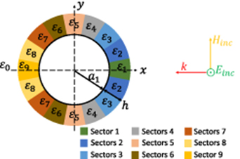
Figure 8. PEC cylinder having radius a1 = λ/2, coated by 16 sectors of dielectric layer and having the thickness h = λ/5, illuminated by an TE-polarized plane wave.
Download figure:
Standard image High-resolution imageTable 2. Permittivities of the 16 optimized sectors.
| Sectors |  r r |
|---|---|
| 1 | 9.8 − j12.31 |
| 2 | 1.3 − j0 |
| 3 | 1.8 − j0 |
| 4 | 2.7 − j0 |
| 5 | 2.8 − j0 |
| 6 | 2.6 − j0 |
| 7 | 1.9 − j0 |
| 8 | 1 − j0 |
| 9 | 1 − j0 |
The sectors at the shadow side of the cylinder (which affect mainly forward scattering) are not filled with any material. In fact, we have noticed that the best choice for these sectors optimized for forward scattering reduction is an epsilon-near-zero material (as in scattering cancellation cloaks) or vacuum, if one does not want to use active materials. The bistatic scattering for this scenario is illustrated in figure 9. It can be observed that the backscattering is very low and that the forward scattering reduction for this design is significantly better than that for the 4-sector inhomogeneous coating presented above. Figure 5 summarizes the normalized total ( ), forward (
 ), and backscattering (
 ) widths. From this analysis, we can see that forward scattering width of the 16-sector coating is reduced by 78% when compared to the forward scattering of the uncoated PEC cylinder. The backscattering and total scattering are reduced by 98% and 65% when compared to the reference case, respectively. Moreover, we can see that the structure proposed in scenario 2 presents better reduction of the total and forward scattering than the structure presented in scenario 1, case 3. However, due to the length reduction of the lossy sector positioned in the front-face, the reduction of backscattering is worse than in case 3 of scenario 1.
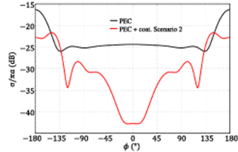
Figure 9. Normalized bistatic scattering width for a PEC cylinder having the radius λ/2 (black) and for a PEC cylinder of radius λ/2 covered with the coating presented in scenario 2 (in red). Illumination by an E-polarized wave is considered. Simulations and calculations have been done for 3 GHz.
Download figure:
Standard image High-resolution imageThe spatial distributions of scattered electric fields for scenario 2 and case 3 of scenario 1 are illustrated in figure 10. It can be seen that with the inhomogeneous coatings with four sectors illustrated in figure 10(b) and 16 sectors illustrated in figure 10(c), the backscattering is very small compared to the uncoated PEC cylinder (figure 10(a)). Similarly, we can see that by increasing the number of passive sectors, we gradually decrease field strength in the shadow zone.
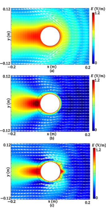
Figure 10. Magnitude of the scattered electric fields and Poynting vectors represented denoting the vector direction of the total field for (a) uncoated PEC cylinder, (b) PEC cylinder coated by the inhomogeneaous coating of scenario 1, case 3 and (c) PEC cylinder coated by the inhomogeneaous coating of scenario 2. The incident electric field is from right to left.
Download figure:
Standard image High-resolution image3.3. Frequency dependence of scattering by coated cylinders
Next we study the frequency bandwidth of sectored scattering-reducing coatings. We compare the frequency responses of the inhomogeneous coating of scenario 1 (case 3) and scenario 2. The PEC cylinder radius equals λ/2 at 3 GHz, and it is covered with coatings having the thickness of λ/5 at the same frequency of 3 GHz. The results of the frequency analysis are shown in figure 11.
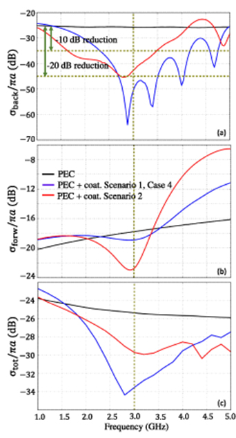
Figure 11. Frequency dependence of scattering by a PEC cylinder having radius λ/2 at 3 GHz and the PEC cylinder coated with inhomogeneous coatings (the thickness is λ/5 at 3 GHz) presented in scenarios 1 and 2. (a) The frequency dependence of the normalized backscattering width. (b) The frequency dependent normalized forward scattering width. (c) The frequency dependency of the normalized total scattering width.
Download figure:
Standard image High-resolution image
Analysing the plots in figures 11(a)–(c), we can observe that with the two inhomogeneous coatings, broadband scattering reduction is achieved for back, forward and total scattering. The backscattering reduction seen in figure 11(a) is more efficient with the 4-sector coating (scenario 1, case 3), especially in the region of 3−4.5 GHz. However, the 16-sector coating is more efficient for backscattering reduction in the region of 1−2.5 GHz. The bandwidth of 62% is achieved with both coatings at the −10 dB backscattering reduction. For −20 dB backscattering width reduction, the 4-sector coating has wider (33%) bandwidth than the 16-sector coating (5%). The forward scattering reduction, shown in figure 11(b), is more significant for the 16-sector coating (scenario 2). The bandwidth of 10.6 % is obtained for −4.5 dB forward scattering reduction with the 16-sector coating. Finally, the total scattering reduction is shown in figure 11(c) for both coatings. Total scattering reduction is obtained in the whole range of 1.5–5 GHz. With the 4-sector coating the total scattering reduction is of −8 dB, while it is −4 dB for the 16-sector coating at the optimized frequency of 3 GHz.
4. Conclusion
In this paper, we have analysed the problem of reduction of scattering from metal (modeled as PEC) cylinders with the diameter of the order of the wavelength. The focus has been on finding reasonably simple, practically realizable solutions. Here, we assume that active (gain) components cannot be used and, moreover, we allow the use of only practically available dielectric materials. In practical application scenarios, the most important requirement is minimization of backscattering. Reduction of forward (and total scattering) is highly desirable, but ideal cloaking is not required provided that the backscattering is very low. In this case, the use of absorbing materials is allowed (we recall that perfect cloaking is possible only using active or lossless structures), giving a possibility to reduce backscattering in a considerably wide frequency range using absorbers. However, the surface area covered by an absorber should be as small as possible, so that there is enough design freedom to shape scattering in other directions using lossless coverings.
As a result of the analysis of known scattering reduction techniques (cloaking and impedance matching), we propose a practical design in form of electrically thin (λ/5) sector-wise homogeneous dielectric coatings. Using the allowed design freedom, we fill the sector which faces the incident waves with a lossy dielectric material, ensuring dramatic reduction of backscattering. Next, we optimize low-loss or lossless material parameters for media, which fill the other sectors, with the goal to minimize the forward scattering amplitude.
We have compared a simple solution based on the use of only four sectors with a more complex structure which has 16 sectors. As expected, a finer control of the angular distribution of the material parameters of the cover offers a possibility to significantly improve performance. As is obvious from the optical theorem, the use of lossy covers (absorbers) to remove backscattering leads to limitations on reduction of forward and total scattering widths. However, the use of an absorbing sector allows us to achieve robust and broadband reduction of backscattering width.
An interesting result of this study is that it is possible to reduce backscattering very significantly even if the width of the lossy sector is small compared to the wavelength (it is usually assumed that one neds to cover the area of the order of λ2). In our 2D study, this expected sector width is of the order of λ. Furthermore, we have studied the frequency bandwidth of the proposed designs and shown that broadband back, forward and total scattering reduction can be achieved using the designed 16-sector coating, and even simpler designs with a smaller number of different materials perform well.
In what concerns practical realizations, we would like to comment that the sector response is determined by the electrical thickness of the layer. This property opens a possibility to use variable-thickness covers if it is difficult to find materials with the permittivities required for a certain thickness of the scattering-reduction coating. Also, concerning the examples of dielectrics with optimal parameters (in our examples), low-loss dielectrics are commercially available, for example in the Rogers substrate family [26] and as low-loss dielectric powders [27, 28]. For the high-loss materials, various composites can be used. For example, porous yttria-stabilized zirconia/silicon carbide (YSZ/SiC) composites are suitable candidates. The relative permittivity of YSZ can be modified by adding appropriate volume fractions of SiC. It has been shown in figure 3 and table 1 of [29] that dielectric constants in the range of 1.5−14 with very high dielectric losses (tanδ > 1) can be obtained when the content of SiC varies from 0% to 97.9%. Although the studies described in [29] have been carried out in the 8–13 GHz frequency band, by adjusting SiC volumes in the YSZ, and by mixing it with low-loss dielectrics if needed, materials having permittivity values close to ɛr = 1.88 − j1.44 and ɛr = 9.8 − j12.31 can be obtained for the lower GHz frequency band. Moreover, powders such as barium titanate and additional lossy compounds can be used to control the real and imaginary parts of the permittivity independently under annealing temperatures and other synthesis conditions, thus allowing the fabrication of highly lossy dielectrics [30]. In addition, the results presented in this paper suggest that further scattering suppression can be achieved using the emerging field of machine-learning-based photonics [25].
We believe that the results of this study will be useful in designing simple and practically realizable scattering-reduction coatings of long metal cylindrical structures for the important but not widely studied case of the cylinder diameter comparable with the wavelength. Furthermore, throughout the paper we have considered TE-polarized incident plane waves, but the same optimization process can be applied for scattering reduction of TM-polarized plane waves of a PEC cylinder by using appropriate scattering coefficients available in [5].
Acknowledgment
The authors wish to thank Dr Costas Valagiannopoulos of Nazarbayev University and members of the Department of Electronics and Nanoengineering, Aalto University including Xuchen Wang and Svetlana Tcvetkova for fruitful discussions.
Appendix A.
For an E-polarized incident plane wave, the scattering width of a PEC cylinder coated with a homogeneous dielectric layer is given by [5]
with ψ being the incidence angle and φ being the scattering angle. The coefficient  is obtained by representing the incident field components as Fourier expansions and by inserting them in the boundary conditions as explained in [5]. Thus,


The prime ( ) in the above equations denotes the derivative with respect to the argument of the Bessel functions. Non-magnetic dielectrics (µr = 1) are considered in this study, and the dielectric is allowed to be lossy (
 ).
).