
Abstract
Electrostatic approaches are successful in explaining the experimentally observed field-induced orientations of the axis with the highest Clausius-Mossotti factor. For conductive or nonconductive, prolate or oblate spheroids, this is always the longest axis when different frequency-dependent dispersions of their effective conductivity along the three principal axes are neglected. Here, it is shown that these orientations correspond to the 'law of maximum entropy production' (LMEP) by comparing the axes-ratio dependencies of the torques calculated with the electrostatic approach with the effective conductivity differences between a suspension with field-oriented and randomly oriented objects. At low volume fraction, the obtained conductivity differences, which enter the LMEP, predict almost exactly the torque curves when plotted over axis ratio of the objects. Since the field-induced orientation at constant field strength increases the effective conductivity, the suspension system obviously does not behave according to the Prigogine principle, which would demand the minimization of energy dissipation and entropy production through object orientation. However, the Prigogine principle requires the suspension system to be close to equilibrium in its linear range. These conditions must be rejected if the LMEP is to be applied. Apparently the LMEP provides a phenomenological criterion for axis orientation, even though it is not yet clear whether and how increased conductivity, power dissipation and entropy production can also be introduced as driving forces at the single object level. However, the results also indicate that the disregard of energy dissipation may not be a problem in the electrostatic description of field-induced object orientation.
Export citation and abstract BibTeX RIS

Original content from this work may be used under the terms of the Creative Commons Attribution 4.0 licence. Any further distribution of this work must maintain attribution to the author(s) and the title of the work, journal citation and DOI.
1. Introduction
The specific impedance or its reciprocal parameter, the complex (specific) conductivity  in S m−1 of homogeneous gaseous, liquid or solid media is changed in the presence of objects or inclusions (complex parameters are underscored). While the conductivity of aqueous media is reduced by objects made of insulating material such as gas, sand, oil or plastics, their conductivity is increased in the presence of conductive objects such as metallic particles. The conductivity of suspensions can be described analytically by means of mixing equations that use the properties of the suspension medium and of the suspended objects (Maxwell 1873, Wagner 1914, Asami et al
1980).
in S m−1 of homogeneous gaseous, liquid or solid media is changed in the presence of objects or inclusions (complex parameters are underscored). While the conductivity of aqueous media is reduced by objects made of insulating material such as gas, sand, oil or plastics, their conductivity is increased in the presence of conductive objects such as metallic particles. The conductivity of suspensions can be described analytically by means of mixing equations that use the properties of the suspension medium and of the suspended objects (Maxwell 1873, Wagner 1914, Asami et al
1980).
Impedance experiments are usually designed to avoid making changes to the properties of the measuring system by the act of measuring. For a suspension, this demands that the field-induced movement, orientation and deformation of the objects by electrokinetic forces are negligible with respect to the thermal noise-related effects. This condition is usually met at field strengths below 1000 V m−1. Above 1000 V m−1, orientation of nonspherical microscopic objects can be observed in DC and AC fields.
For any given volume fraction, the effect of the objects on the suspension's conductivity depends on the shape, orientation and arrangement with respect to the external electric field (Pauly and Schwan 1959, Asami et al 1980, Foster and Schwan 1996, Sekine et al 2002, Stubbe and Gimsa 2015). While field line distributions provide an exact picture of the relations for nonspherical objects, analytical description by mixing equations is based on depolarizing coefficients, which were considered by Stratton (1941), before explicit expressions were derived for spheroidal objects (Stille 1944) and for the general ellipsoidal shape (Osborn 1945, Stoner 1945).
A more intuitive, electro-technical approach to the impedance effects of suspended objects is provided by 'influential radii' that are directly related to the depolarizing coefficients (Gimsa and Wachner 1999). This approach allows for a separation of the electric and geometric problems by providing the geometries for exact resistor-capacitor models of the frequency-dependent Clausius-Mossotti factors (CMFs) for objects of the general ellipsoidal shape. Influential radii have been successfully applied in the modeling of AC-electrokinetics such as dielectrophoresis, electrorotation and orientation (Gimsa 2018), induced transmembrane potentials of biological cells (Gimsa and Wachner 2001) or the impedance of suspensions (Stubbe and Gimsa 2015).
Impedance and AC electrokinetic models are generally based on the electro-quasistatic (EQS) approximation for slowly varying time-harmonic electromagnetic fields (cf. appendix A). The approximation is generally used to reduce the complexity of the impedance and AC electrokinetic models.
A number of different approaches can be employed to model the orientation of nonspherical objects. One initial approach that is followed in most cases is also used as a reference here. It explains the orientations by means of the different torques induced around the three principal axes of ellipsoidal objects from the interactions of the induced dipole moment with the inducing field (Gruzdev 1965, Asencor et al 1993, Jones 1995, Gimsa 2001). In linear AC fields, the torque criterion results in the orientation of the axis of the highest real part of the CMF in the field direction.
The second approach assumes that the free energy of the suspension system is minimized by the objects' orientation (Schwarz et al 1965, Saito et al 1966, Miller and Jones 1993). Even though it has been successfully applied in the interpretation of orientation experiments (Ferris and Griffin 1977, Ascoli et al 1978), it is believed that the free energy criterion is not generally appropriate for dissipative systems (Landau and Lifshitz 1984, Sauer and Schlögl 1985).
Here, a new approach considers the entropy production. At constant field strength, the entropy production in thermal equilibrium is proportional to the dissipation of electric energy, which is proportional to the suspension's conductivity. Under the assumption that the suspension system is near equilibrium in its linear range, then—on the basis of Prigogine's principle - entropy production ought to be minimized by object orientation (Prigogine 1947, Onsager and Machlup 1953, Prigogine 1967, Stenholm 2008). Nevertheless, experiments do suggest that field-induced orientations reduce the impedance of the suspension. Accordingly, reorientations would be more likely to follow the law of maximum entropy-production (LMEP) (Martyushev and Seleznev 2006, Grinstein and Linsker 2007, Niven 2009). This law states: A system will select the path or assemblage of paths out of the available paths that minimizes the (electric) potential or maximizes the entropy at the fastest rate (Swenson 1989).
In order to bring light into this new approach of explaining orientation effects, this manuscript considers the field-induced orientation of conductive or insulating rotational ellipsoids, i.e. spheroids. Consideration is given to how the CMFs along the different axes govern the field-induced orientation of the individual objects (Gimsa 2018) and how this orientation influences the impedance of the suspension using Maxwell-Wagner's mixing equation (Stubbe and Gimsa 2015). While the derivations are based on relations, which have each been experimentally tested, the hypothesis being tested here is that the orientations observed increase the dissipation of electric energy, i.e. the entropy production. It is hypothesized that the LMEP and the orientation torque criterion are largely equivalent and apply to the orientation of suspended objects.
2. The model
2.1. Depolarizing coefficients and influential radii
For closed surfaces of the second degree that describe ellipsoidal cavities or objects, depolarizing coefficients ( ) are defined along the three principal semiaxes a, b and c. Their sum is always unity (cf. table 1) (Stratton 1941, Stille 1944, Osborn 1945, Stoner 1945, Landau and Lifshitz 1984):

Inside cavities or homogeneous objects of very low polarizability, a homogeneous external field (or field component)  in parallel with the semiaxes a of the object induces the constant local field (or local field component):

with  and
and  being the influential radius and the relative influential radius (maximal field amplification factor) along semiaxes a. Analogous expressions hold for each principal axis. For reasons of simplicity, the vector notation was not used.
Table 1. Parameter limits relevant for the field-induced orientation of oblate and prolate spheroids. The oblate and prolate branches are separated by the spherical shape (fourth column). The axis-ratio branches of the highest CMFs and suspension conductivities are marked. For conductive and nonconductive spheroids, these are assigned to the longest axes, i.e. to a and c for oblate and prolate spheroids, respectively. The expressions for the limiting suspension conductivities for the oblate and prolate shapes show that the orientation of the longest axis corresponds to the highest conductivity.

|
For ellipsoidal objects, the influential radii along each principle semiaxis are the distances from the respective symmetry planes to those undisturbed equipotential planes that just touch the respective pole of a 'vacuum' object of identical shape (Gimsa and Wachner 2001). The properties of such objects are considered for effective conductivity relations of  for the internal (index i) and external (index e) media. Inside spherical cavities where
  the local field
  along semiaxis a, is increased by a factor of
  with respect to the undisturbed external field
  (Bernhardt and Pauly 1973).
After combining equations (1) and (2), we obtain a relation for the inverse relative influential radii of spheroids with  (Gimsa 2001):

Figure 1 shows the depolarizing coefficients and the influential radii of spheroids over the axis-ratio calculated from equations (1) and (3) as described by Gimsa and Wachner (2001). For approximating equations, see Maswiwat et al (2007).

Figure 1. Axis-ratio dependence of the depolarizing coefficients and relative influential radii of oblate and prolate spheroids perpendicular to (continuous lines) and along (dashed lines) their symmetry-semiaxis c. The vertical solid line marks the spherical shape. The vertical dotted line marks the shape of a prolate spheroid with an axis ratio of a:b:c = 1.61:1.61:1 (cf. figure 2).
Download figure:
Standard image High-resolution image2.2. Clausius-Mossotti factor (CMF) and dipole moment
For ellipsoid objects, the component  of the induced dipole moment along semiaxis a is proportional to the external field component
  and the permittivity
  of the external medium:

with  being the volume of the object. The CMF component:

describes the dependence of  on the effective polarizability of the objects, for example the frequency dependence of ellipsoidal objects, in the form of normalized differences of the constant local field or of the potentials at pole a in the presence
(
 ) and in the absence (
 ) of the object (figure 2) (Landau and Lifshitz 1984). Analogous expressions hold along each semiaxis. Note that the Laplace equation ensures that the effective field is constant inside closed surfaces of the second degree. Closed analytical solutions can be derived for the polarization of spheroidal objects.

Figure 2. Schematic equipotential lines in the absence (left hemispheroid) and presence (right hemispheroid) of an oblate, low polarizable, homogeneous spheroid with an axis ratio of a:b:c = 1.61:1.61:1. The spheroid is oriented with semiaxis a in the direction of the external field component 
 does not induce potentials at the poles of semiaxis b or symmetry-semiaxis c. The influential radius
  determines the most distant equipotential plane that may touch pole a . For low polarizable spheroids, the influential radius
  'grips' the external potential
  which is the highest possible potential at pole a.
Download figure:
Standard image High-resolution imageAt the pole of semiaxis a, the two limiting cases for the potentials are  and
and  for nonconductive, low polarizable objects (
 ) and conductive, highly polarizable objects (
 ), respectively. Because the conductivities of objects and media are being considered here, the terms 'nonconductive' and 'highly conductive' are used for objects that are of much lower or much higher polarization than the suspension medium.
With 
 (figure 2) and the definition of the influential radius (equation (2)), for nonconductive objects, equation (5) reads:

and

For conductive objects with  we obtain:

and

The limiting shapes of infinitely thin disks and infinitely long cylinders correspond to the limits of  and
and  respectively. The limiting conductivity cases can be approached for the same object when it exhibits strong frequency-dependent dispersions, such as in a biological cell. Figure 3 shows plots of the CMFs of nonconductive and highly conductive spheroids.

Figure 3. Axis-ratio dependence of the CMFs of nonconductive (low) and highly conductive (high) spheroids along the a (continuous line) and c (dashed line) semiaxes. The torques (dashed double-dot line) acting around semiaxis b were calculated as CMF differences  for the two conductivity cases (equation (10)). Note, that real part and absolute value of the factors are identical when dispersions are neglected. The vertical dotted line corresponds to the prolate spheroid in figure 2.
Download figure:
Standard image High-resolution image2.3. Orientation torque
The time-averaged torque  acting on an ellipsoid in a circular polarized field is given by the real part of the cross-product of induced dipole moment and conjugated field:

In component notation, the time-averaged torque  is:
is:
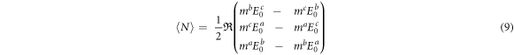
For spheroids, semiaxes a and b cannot be distinguished. To determine the orientation, it is sufficient to consider semiaxes a and c. Here, the b-components of the external field and the induced dipole moment can be neglected ( ). For simplicity, it can be assumed that semiaxes a and c are aligned at an angle of 45° to the external field, their inducing field components are equal in magnitude (
 ) and the induced torque only depends on the a and c-components of the induced dipole moment. Combined with equations (4), (9) now reads:
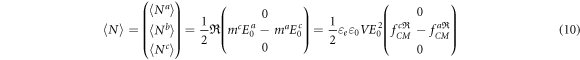
The object is oriented around semiaxis b. After neglecting the pre-factors that are equal for all semiaxes, the induced torque N is proportional to the difference in the real parts of the CMFs along axes a and c. General considerations show that the torque criterion predicts the stable orientation of the axis of the highest real part of the CMFs in the field direction regardless of the initial orientation angle (Gimsa 2001, Jones 1995). Although the torque also disappears for precise alignment of an axis with a lower CMF, this alignment is unstable.
To decide which axis is oriented, the CMFs in equations (6a ) and (6a ) (nonconductive spheroids) or equation (7a ) and (7b ) (conductive spheroids) in the oblate and prolate axes-ratio branches can be compared with simple inequations after reducing the number of variables in either one of the two equations to be compared (for a graphical comparison cf. figure 3). In both conductivity cases, the CMFs for semiaxes a and c are higher for oblate and prolate spheroids, respectively, always resulting in the orientation of the longer semiaxis in the field direction.
2.4. Mixing equation, axis-ratio and orientation dependence of the suspension's conductivity
In order to demonstrate that the orientation of the longest axes increases the conductivity for suspensions of nonconductive and conductive spheroids, the conductivities for the two alternative orientations are compared (clearly, the random orientation will result in a conductivity that is in between these two cases). The suspension conductivity  is derived by Maxwell-Wagner's mixing equation (Wagner 1914), which has been extended to suspensions of general ellipsoids (Fricke 1953, Asami et al
1980, Stubbe and Gimsa 2015). For the orientation of semiaxis a in field-direction, it reads:
is derived by Maxwell-Wagner's mixing equation (Wagner 1914), which has been extended to suspensions of general ellipsoids (Fricke 1953, Asami et al
1980, Stubbe and Gimsa 2015). For the orientation of semiaxis a in field-direction, it reads:

with  and p standing for the complex conductivity of the suspension medium and the volume fraction of the objects. In this equation, the effects of objects on the suspension's conductivity does not depend on the objects' size but only on their volume fraction, shape and orientation. Equation (11) can be rearranged thus for the suspension's conductivity:

Analog expressions hold for the orientations of semiaxes b and c of general ellipsoids. For nonconductive spheroids, with equations (6a
) and (6b
) the suspension conductivities 
 and
and  are obtained for the orientations of semiaxis a, c and for the random orientation, respectively:


With equation (7) for conductive spheroids, we obtain:


Note that equations (13a
) and (13b
), as well as (14a
) and (14b
) are also valid for the general ellipsoidal shape. The spherical shape with  separates the conductivity behavior of oblate and prolate spheroids. With equations (13a
)–(13c
) for nonconductive spheres, we obtain the common separation point:
separates the conductivity behavior of oblate and prolate spheroids. With equations (13a
)–(13c
) for nonconductive spheres, we obtain the common separation point:

and equations (14a )–(14c ) for conductive spheres give us:

Figure 4 illustrates the results. The presence of 10% v/v (p = 0.1) nonconductive and conductive spheres reduces and increases the conductivity to 0.0857 S m−1 and 0.1333 S m−1 with respect to the conductivity of the suspension medium of 0.1 S m−1.

Figure 4. Axis-ratio dependence of the conductivity of suspensions of nonconductive (below 0.1 S m−1) and conductive (above 0.1 S m−1) spheroids for different orientations. Note the different ordinate scaling below and above 0.1 S m−1.
Download figure:
Standard image High-resolution imageThin nonconductive disks are highly efficient in reducing the conductivity when oriented with their symmetry axis in field direction, whereas nonconductive needles are more efficient when oriented perpendicular to the field. When their longest axes are oriented in field direction, their 'shape effect' disappears and their presence should reduce the suspension's conductivity by up to 10%, to 0.09 S m−1, which represents the pure 'volume effect' of the objects (top plateau limits at the bottom of figure 4). In these cases, the relative influential radii of the oriented axes are unity, i.e. the presence of the objects does not alter the field distribution but just excludes the object volume from conduction. The slight overshooting of the plateaus above 0.09 S m−1 is caused by the limits of the mixing equation. The overshoot largely disappears at p = 0.01.
Conductive disks and needles are most efficient in increasing the conductivity when oriented with their longest axes in field direction (figure 4). Plateaux above the conductivity of the suspension medium are approached for oblate (approx. 0.110 S m−1) and prolate (approx. 0.122 S m−1) shapes when very flat disks and very long needles are oriented with their symmetry axes in parallel and perpendicular to the field, respectively. Whereas the disks electrically bridge 10% of the suspension's volume, without influencing the field distribution in the suspension medium (the shape effect disappears and their presence can be compared to a reduction of the electrode distance by 10%), the needles, which can be compared to the limiting case of infinitely long cylinders, 'collect' field lines from their surrounding medium, thereby reducing the suspension's conductivity more efficiently than the disks.
If the LMEP applies, it would govern the field-induced conductivity increase from the field-free random orientation to certain oriented states. Figure 5 presents the conductivity differences induced by the orientation of axis a or c with respect to the random orientation. These differences are proportional to changes in the dissipation of electrical energy (equation (17)).

Figure 5. Axis-ratio dependence of the suspension's conductivity differences (oriented minus random orientations) caused by the orientation of different axes of nonconductive and conductive spheroids with respect to the random orientation, i.e. the abscissa at zero conductivity difference (not shown) corresponds to the random orientations in figure 4. Curves with positive conductivity differences correspond to the axis orientations predicted by the LMEP, i.e. the orientation of the semiaxes a and c for oblate (4th quadrant) and prolate spheroids (1st quadrant), respectively.
Download figure:
Standard image High-resolution imageIn order to test the hypothesis that the conductivity differences resulting from the object orientation are proportional to the orientation torques, the torque curves in figure 3 were compared with the respective conductivity changes. In figure 6, the absolute values of the torques were plotted and compared with the positive conductivity differences in figure 5. The conductivity differences were multiplied by the factors shown in figure 6 and used without units. While the qualitative similarities were already conspicuous for object fractions of p = 0.1, they were almost accurate for p = 0.01. Note that the fitting accuracy of the dotted curves for p = 0.1 can be easily improved by varying the proportionality factors. The factor of ten was applied to the p = 0.01 values in order to demonstrate the systematics in the improvement of fit for lower object fractions.

Figure 6. Axis-ratio dependence of the torques around semiaxis b (solid lines, cf. equation (10) and figure 3) compared with the positive conductivity differences of figure 5 for p = 0.1 (dotted lines). The improved accuracy of Maxwell-Wagner's mixing equation for p = 0.01 results in almost accurately corresponding fits (dashed curves).
Download figure:
Standard image High-resolution image
3. Discussion
3.1. General and thermodynamic aspects
The two existing approaches to modelling orientation effects only consider the static stability of the orientation. The first approach explains the orientations on the basis of the different torques induced around the three principal axes of ellipsoidal objects (Asencor et al 1993, Gruzdev 1965, Jones 1995, Gimsa 2001). The second approach assumes that the energy stored by a single object depends on its orientation in the field. For ellipsoidal objects, there are three possible orientations with 'stationary potential energy', of which only the 'correct orientation' is stable, which has minimal energy (Saito et al 1966, Miller and Jones 1993). Both approaches are based on EQS considerations, whereby power dissipation and thermally induced movements are neglected.
A third approach is proposed here, based on the LMEP and which demands the maximization of entropy production (Swenson 1989). After object rearrangement processes and thermal equilibration processes under the influence of the field have completed, a dynamic equilibrium is established and the energy dissipation corresponds to the steady entropy production  at the temperature T (Atkins 1994):

 is Rayleigh's dissipation function, which can generally be calculated by products of fluxes and forces.
  's electrical version corresponds to the power calculated from currents and potential differences (Scaife 1989, Glaser 2012). In the volume V, it is given by the product of the real part of the conductivity of the suspension
  and the square of the field strength.
It is proposed that the LMEP is realized during object orientation, which is retarded by the viscous properties of the suspension, and holds for the oriented state. As far as the author is aware, this approach has not yet been exploited. It does not violate thermodynamic principles such as the Curie-Prigogine principle, which prohibits the coupling of scalar and vectorial quantities in isotropic systems, since electric fields and moments are vector parameters. The orientation process seems to be in line with the Prigogine-Glansdorff principle for dissipative structures, which allows only positive changes in entropy production due to the induced effects, even those that are not considered here, such as translation, rotation and pearl-chain formation after field-on. Obviously, the system does not behave according to the Prigogine principle, which would demand the minimization of entropy production through object orientation. Nevertheless, Prigogine's principle requires the suspension system to be approximately in equilibrium in its linear range (Onsager and Machlup 1953, Prigogine 1967, Stenholm 2008). These conditions must be rejected if the LMEP is to be applied. It is clear that the conductivity of the suspension shows nonlinear behavior as it changes with the field-induced orientation, even if every thermal effect on model parameters such as viscosities, conductivities and permittivities is neglected. After field-off, however, the Prigogine principle probably regulates the path to the state of equilibrium with random orientation and without entropy production.
3.2. Orientation and impedance
As shown in theory and experiments, the axis of highest real part of the CMF is oriented in linear fields (Jones 1995, Gimsa 2018, Gimsa et al 2018a). The resulting increase in the suspension conductivity leads to an increase in the electrical power dissipation at a constant field strength and/or to a reduction in the field strength. This suggests that the maximum entropy-production principle applies to field-induced orientations (Martyushev and Seleznev 2006, Grinstein and Linsker 2007, Niven 2009).
Theoretical results for the conductivity of suspensions of homogeneous spheroids have been discussed before (Gimsa and Gimsa 2017), together with a first consideration of the ideas now elaborated here. As shown, field-induced orientations reduce the impedance of suspensions for spheroids in the oblate and prolate axis ratio branches for the two limiting conductivity cases. All results are summarized in table 1, starting from the depolarizing coefficients and influential radii that are used to consider the CMFs and effective suspension conductivities. Table 1 shows that it is always the longest axis that has the highest CMF and is aligned. This alignment, in turn, leads to the highest suspension conductivity. However, systematic considerations of the whole parameter space and the limits of the approach are necessary to arrive at a general conclusion including the general ellipsoidal shape.
3.3. Open questions
One initial open question is whether the LMEP also applies to intermediate CMFs, e.g. those resulting from frequency-dependent dispersions. Generally, the effective conductivity of objects with thin insulating shells, such as the membranes of biological cells or particles with interfacial redox-current transitions, may change with frequency and approach the two limiting cases  and
and  in dependence on the frequency of the measuring field. Equations (6a
) and (7a
) constrain the real part of the CMF along semiaxis a to values between those of nonconductive and highly conductive general ellipsoids. If the CMFs change along any of the three semiaxes, e.g. through dispersions along axis a, the conductivity of the suspension will move in a range determined by the difference between equations (13a
) and (14a
):
in dependence on the frequency of the measuring field. Equations (6a
) and (7a
) constrain the real part of the CMF along semiaxis a to values between those of nonconductive and highly conductive general ellipsoids. If the CMFs change along any of the three semiaxes, e.g. through dispersions along axis a, the conductivity of the suspension will move in a range determined by the difference between equations (13a
) and (14a
):

Because 0 < p < 1, equation (18) is always positive, which shows that dispersions that increase the polarizability of ellipsoidal objects lead to an increase in suspension conductivities. Equations (6a
) and (7a
) do not introduce imaginary components into equation (18). Nevertheless, for intermediate CMFs in the dispersion frequency range, the products of the imaginary part of  and the imaginary part of the CMF contribute to the real part of
  However, these contributions are generally positive and modulate the frequency dependence of the real parts only moderately (Foster and Schwan 1996, Stubbe and Gimsa 2015). Analogous considerations apply to each semiaxis, which allows the conclusion that the LMEP also applies in dispersion ranges for stably oriented general ellipsoidal objects.
Nonetheless, the different membrane curvatures and influential radii at the poles of the different semiaxes may lead to different frequency dependencies of the dispersions along the semiaxes. Depending on the external conductivity, this can lead to frequency windows with permutations of the axes with the highest real part of the CMF and to reorientations as observed experimentally on triaxial chicken red cells (Gimsa et al 2018a).
A second open question is whether such reorientations and the orientation of shorter axes with the highest CMFs in the dispersion ranges increases the conductivity of the suspension also for general ellipsoids. However, the general description of the problem is complicated by the imaginary parts and changing signs of the parameters.
A third question is whether the LMEP is causally connected with the induced torques and - if this is indeed the case - how the torque magnitudes can be obtained from the orientation-dependent conductivity or energy dissipation changes (cf. appendix B). Figure 6 shows that the torque and conductivity-difference curves are very similar. Although both the conductivity differences obtained for different orientation states and the torques are based on equations derived from CMFs (equation (16)), a simple mathematical relationship between the mixture equations and the torques cannot be directly derived. The problem occurs because the torque equations are exact while the mixing equations are approximate ones that are the more correct the lower the object fractions are. One hint that the LMEP approach is correct is the improved correspondence between the torque and conductivity-difference curves for p = 0.01 (figure 6).
4. Conclusion and outlook
The field alignment of homogeneous prolate and oblate spheroids leads to the highest conductivity of a suspension. Apparently the LMEP provides a phenomenological criterion for the axis orientation, but like many thermodynamic parameters it may not directly explain the origin of the forces and moments at the microscopic or single object levels. There is hope that increased conductivity, power dissipation and entropy production can also be introduced as driving forces for such electrokinetic effects as dielectrophoretic translation and the formation of pearl chains (Parthasarathy and Klingenberg 1996, Mehrle et al 1988, Gimsa et al 2018a). For spherical objects, the mixture equation requires the assumption of a volume fraction below 0.1 for the electrical interactions between the suspended objects to be negligible (Maxwell 1873, Wagner 1914). Nonspherical objects may require lower volume fractions, as figure 6 suggests. However, the almost exact correspondence of the obtained curves at very low volume fractions suggests that the disregard of energy dissipation may not be a problem in electrostatic descriptions. It is possible that the comparison of the induced torques with the conductivity differences calculated from Maxwell-Wagner's mixing equation can be used to test the accuracy of the mixing equation for given object shapes and concentrations.
Probably triaxial chicken red blood cells can provide an experimental access to the conductivity criterion, since they are largely monodisperse and their orientation corresponds to the torque criterion (Gimsa et al 2018a). If LMEP provides a mathematical criterion for the relative probabilities of more or less favorable field-induced object arrangements, e.g. in Monte Carlo simulations of suspended objects, this may be important in biotech applications and for such electro-rheological applications as electrical clutches in which field-induced orientation and aggregation change the viscosity of a suspension (Parthasarathy and Klingenberg 1996, Ikazaki et al 1998, Wang et al 2015, Shah et al 2020).
Besides the entropy production during and after field-induced orientation, another interesting thermodynamic aspect is the decrease in the rotational degree of freedom due to orientation. This reduction changes the contribution of the rotational entropy of the objects to the total free energy of the suspension system, an aspect that requires description by statistical rather than by phenomenological thermodynamics (Perutkova et al 2010, Gimsa et al 2018b). In the system considered here, the reduction of entropy by restrictions on rotational freedom occurs at the expense of permanent entropy production. Interestingly, this situation is comparable to that of living systems that are in open dynamic equilibrium. Entropy production allows them to maintain their low entropic state.
Acknowledgments
Ms Jessica Schröder is acknowledged for her help with the figures. R Sleigh is acknowledged for his help with the language.
The author has declared no conflict of interest.
Appendix A
Appendix. AC-electrokinetic modeling: Maxwell's equations in the electro-quasistatic (EQS) approximation
The macroscopic electromagnetic theory is based on the four Maxwell equations and three material laws (Maxwell 1873). To reduce the complexity of the models, the EQS approximation for slowly varying time-harmonic electromagnetic fields can be used. For such fields, the wavelength must be large compared to the characteristic dimension  of the model region, i.e.
  where
where  is the complex wave number for lossy dielectric media:

with ω, μ, 
 and
and  standing for the circular frequency, the magnetic permeability, the electric permittivity, the specific conductivity, and the imaginary unit respectively. The permittivity
  and the permeability
  are defined by their relative material (index r) and vacuum parameters (index 0). In the EQS approximation, only displacement currents are taken into account
  while any changes in the magnetic flux are neglected
  (Haus and Melcher 1989, Dirks 1996). This leads to simplified a set of Maxwell equations:


with 


 and
and  denoting the electric field strength, the magnetic field strength, the dielectric displacement, the magnetic induction, and the volume charge density, respectively. The overall current density,
  is the sum of the impressed (source) current density,
  and the conduction current density,
  The electric field phasor
  in equation (A2) is curl-free and can be described as the gradient of a complex potential:

Note that these assumptions reduce the problem size for numerical EQS models by two thirds, since only scalar potentials need to be calculated and no vector fields. After summarizing equations (A2)–(A6), the complex divergence equation or Poisson equation is obtained:

It ensures continuity and can be used to calculate the potential  If only induced charges are taken into account, equation (A7) can be further simplified to the complex Laplace equation:

This equation forms the fundament of AC-electrokinetic and impedance modelling. For aqueous media, the relative permittivity  and relative permeability
  can be considered constant in the frequency range from less than 1 Hz to above 1 GHz. For aqueous media, the material parameters are
  and
and  Assuming a specific conductivity of
  and the criterion
  equation (A1) can be used to calculate upper limits for the characteristic dimensions R. We obtain 11.2 mm, 3.6 mm, 1.12 mm, 340 μm, and 53 μm for frequencies of 100 kHz, 1 MHz, 10 MHz, 100 MHz, and 1 GHz, respectively. In the conductivity range (0.01–1.3 S m−1) used for cell and particle characterization, these values are largely independent of the conductivity of the medium.
Appendix B
Appendix. On the relation between object orientation and the suspension's conductivity
An LMEP approach relating the torque magnitudes to the orientation-dependent conductivity or energy dissipation changes must be based on the field-induced changes in the state of the system, even if the coefficient of proportionality required to determine the causality between torque and entropy production or energy dissipation is not immediately clear. A derivation can start from the dielectric displacement  in media:

where 
 stand for the permittivity and field strength.
  is the polarization, i.e. the volume density of molecular dipoles in Cm/m3. By extending the dielectric displacement to the permittivity of a suspension of oriented objects
  we can write:

with  being the permittivity of the suspension for the random orientation without field
 is the polarization contribution of object orientation:

For a chamber of cuboid geometry with plane parallel electrodes of area A and distance d, orientation induces the capacitance difference:

For the angular frequency ω, the permittivity difference can be expressed as the positive conductance difference  (cf. table 1) via the dispersion relation:

where  is the conductivity difference due to object orientation. Equation (B5) shows that the comparisons in figure 6 are physically meaningful, since the differences in conductivity can actually be traced back to differences in the volume density of dipoles based on field-induced object orientations. Note that the increase in polarization that follows the AC field is the result of increased polarizability of the suspension through the much slower AC electrokinetic effects, such as electro-orientation.