


1. Introduction
In fusion development, tokamak research is now in the phase of demonstrating burning plasmas with the thermonuclear test reactor ITER. Many research activities around the world are concentrated on supporting research works for ITER operation. On the other hand, stellarator research, which is considered to be very important as an alternative approach to a fusion reactor with its great advantage in steady-state operation, is in the concept development phase. There are different approaches for the core magnetic confinement and plasma peripheral structures for particle and heat removal. At the National Institute for Fusion Science (NIFS) in Japan, the Large Helical Device (LHD) experiment is now in the fine physics research phase for understanding the isotope effect of confinement (Takeiri et al. Reference Takeiri, Morisaki, Osakabe, Yokoyama, Sakakibara, Takahashi, Nakamura, Oishi, Motojima and Murakami2017; Yamada et al. Reference Yamada, Takana, Seki, Suzuki, Ida, Fujii, Goto, Murakami, Osakabe and Tokuzawa2019). In the Max-Planck Institute of Plasma Physics (MP-IPP) in Germany, the new experiment of Wendelstein 7-X (W7-X) has started the validation of plasma confinement in the optimized magnetic configuration design (Pedersen et al. Reference Pedersen, Otte, Lazerson, Helander, Bozhenkov, Biedermann, Klinger, Wolf and Bosch2016; Wolf et al. Reference Wolf, Ali, Alonso, Baldzuhn, Beider, Beurskens, Biedermann, Bosch, Bozhenkov and Brakel2017). In China, the joint project of NIFS and Southwest Jiaotong University (SWJTU) is starting to construct a new quasi-axisymmetric stellarator (CFQS) for the validation of one of the advanced stellarator concepts of quasi-axisymmetry (Xu et al. Reference Xu, Liu, Xiong, Shimizu, Kinoshita, Isobe, Okamura, Nakata, Yin and Wan2018; Isobe et al. Reference Isobe, Shimizu, Liu, Liu, Xiong, Yin, Ogawa, Yoshimura, Nakata and Kinoshita2019).
In designing the magnetic configuration of an experimental device, the first priority is placed on designing the configuration of the core confinement region. However, we know now that, without the proper design of the magnetic configuration of the peripheral region, the concept is not useful for a fusion reactor. This is called ‘divertor design’ because the most important physics issue related to the peripheral magnetic configuration is particle and heat removal. For the two largest stellarator experiments, LHD and W7-X, these devices have different divertor structures, which strongly depend on the structures of the main magnetic configurations. In LHD, the intrinsic helical divertor has divertor magnetic field lines connecting the ergodic boundary layer of the core region and the divertor plates on the wall (Masuzaki et al. Reference Masuzaki, Morisaki, Shoji, Kubota, Watanabe, Kobayashi, Miyazawa, Goto, Morita and Peterson2006; Kobayashi et al. Reference Kobayashi, Feng, Morita, Masuzaki, Ezumi, Kobayashi, Chowdhuri, Yamada, Morisaki and Ohyabu2010). In W7-X, the island divertor provides a sophisticated divertor structure combined with low-order islands created near the boundary of the core confinement region (Renner et al. Reference Renner, Boscary, Greuner, Grote, Hoffmann, Kisslinger, Strumberger and Mendelevitcsh2002; Suzuki & Geiger Reference Suzuki and Geiger2016). Intensive theoretical and experimental researches of island divertor performances have been reported, including the former device of W7-AS, which preceded the W7-X programme (Feng et al. Reference Feng, Sardei, Grigull, McCormick, Kisslinger and Reiter2006, Reference Feng, Kobayashi, Lunt and Reiter2011, Reference Feng, Beidler, Geiger, Helander, Hölbe, Maassberg, Turkin and Reiter2016; Xhang et al. Reference Zhang, König, Feng, Burhem, Brezinsek, Jakubowski, Buttenshön, Niemann, Pabone and Krychowiak2019).
For the new stellarator CFQS in China, we are designing an island divertor configuration which provides a clear separatrix between the core plasma region and the peripheral plasmas and sufficiently long connection lengths of magnetic field lines between the plasma boundary and the wall. The importance of the control of the rotational transform is discussed because a significant level of the bootstrap current is expected to appear for the quasi-axisymmetric stellarators. Basic experimental studies for the verification of the island divertor concept for the quasi-axisymmetric stellarators will be possible for the small device with wide flexibility of the operation.
2. Magnetic configuration of CFQS
A quasi-axisymmetric magnetic configuration design of CFQS was started based on the previous work of an advanced stellarator design, CHS-qa (Okamura et al. Reference Okamura, Matsuoka, Nishimura, Isobe, Nomura, Suzuki, Shimizu, Murakami, Nakajima and Yokoyama2001, Reference Okamura, Matsuoka, Nishimura, Isobe, Suzuki, Shimizu, Ida, Fujisawa, Murakami and Yokoyama2004). The aspect ratio was determined as 4.0 instead of 3.2 of CHS-qa in order to take a smaller risk in the design of modular coils for a small device. The major radius of the device is 1 m. We took one of the inner magnetic surfaces from CHS-qa design for vacuum equilibria and defined the last closed magnetic surface (LCMS) of CFQS using the shape of that magnetic surface. The toroidal period number is N = 2. Three poloidal cross-sections of the LCMS are shown in figure 1. These figures are VMEC code (Hirshman & Whitson Reference Hirshman and Whitson1983) output as a target configuration of the modular coil design. Modular coils were designed to realize such a magnetic configuration with a choice of the number of coils around the torus as 16 (Liu et al. Reference Liu, Shimizu, Isobe, Okamura, Nishimura, Suzuki, Xu, Zhang, Liu and Huang2018; Shimizu et al. Reference Shimizu, Liu, Isobe, Okamura, Nishimura, Suzuki, Xu, Zhang, Liu and Huang2018). The success of this coil design was the most important contribution to the finding of a divertor concept for CFQS. Figure 2 shows the punctual plots of the vacuum magnetic field lines (magnetic surfaces) produced with these modular coils (for the third cross-section in figure 1). The red line shows the LCMS of the target configuration in the modular coil design. The magnetic field produced by the modular coils has many closed magnetic surfaces with a larger area beyond the target LCMS.
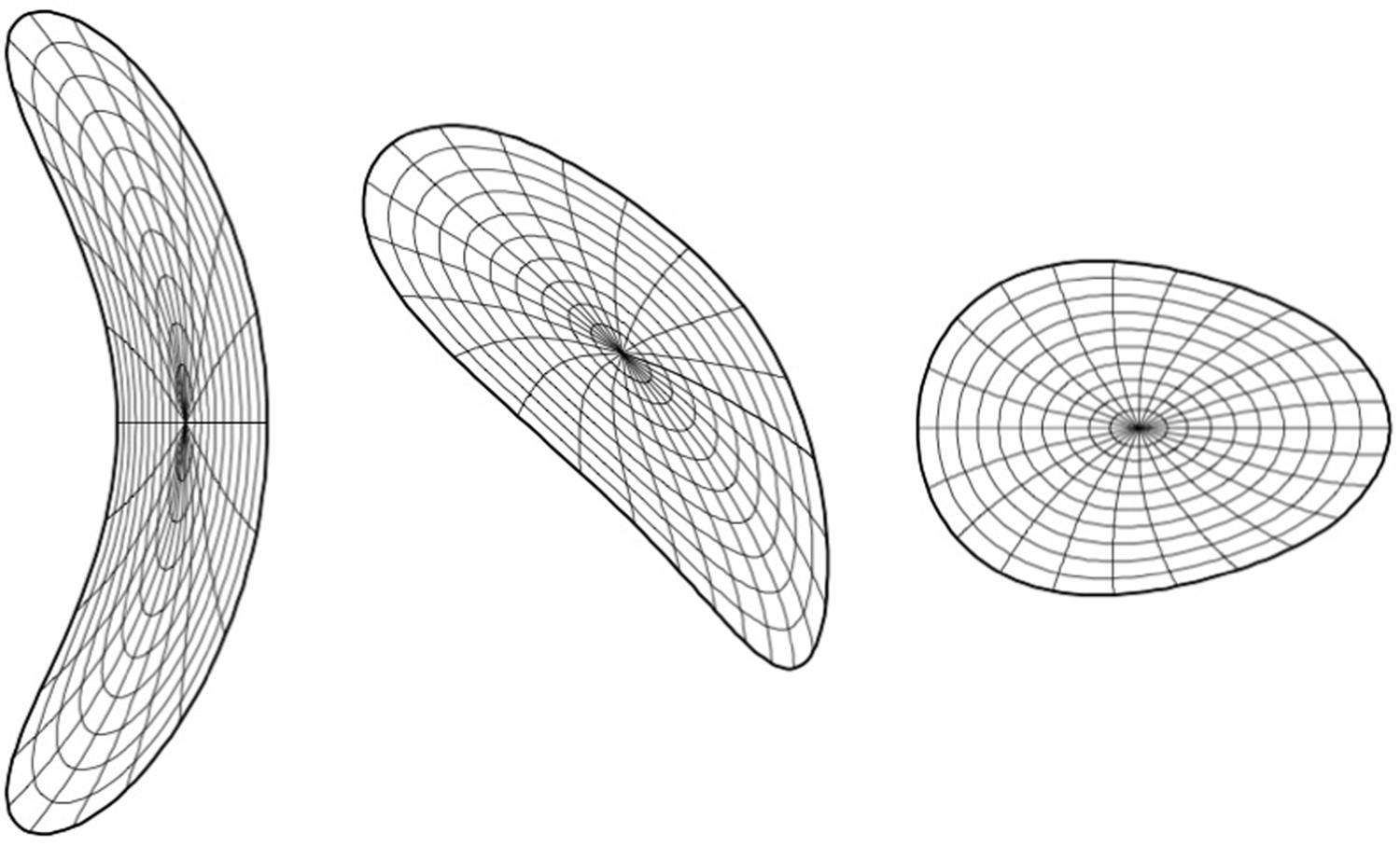
Figure 1. Last closed magnetic surfaces for CFQS advanced stellarator design. Cross-sections for three toroidal positions are shown.

Figure 2. Punctual plots of magnetic surfaces for CFQS configuration produced by 16 modular coils. The red line corresponds to the LCMS of the third plot in figure 1.
The result of the magnetic structure outside of the LCMS (defined by VMEC) does not come from the target configuration. In fact, another modular coil design with 20 coils with the same target configuration gave similar magnetic surfaces inside the LCMS but the boundary configuration is very different. It has a stochastic layer just outside of the LCMS with small islands (n = 2/m = 6) surrounded by the stochastic layer.
The blue (lower) line in figure 3 shows the profile of the rotational transform of the vacuum magnetic configuration produced by the 16 modular coils. A very flat profile for the outer region is important for creating large islands for the divertor configuration. The rotational transform profile of W7-X is also flat, but not as flat as that of CFQS. The polarities of the weak shear of both devices are different; namely, the CFQS has a weak negative shear (in the stellarator terminology) at the boundary while W7-X has a positive shear. A black arrow shows the position of the averaged minor radius of the LCMS of the target configuration. Although we decided upon an aspect ratio of 4.0 for the CFQS device, it is technically possible to create a larger confinement region if we design the vacuum chamber with a sufficiently large size to provide space for such larger closed magnetic surfaces. A control of plasma boundary with a movable limiter might be a possible choice for plasma operation in experiments.

Figure 3. The blue line shows the rotational transform profile of the vacuum field of the CFQS. The arrow indicates the position of the LCMS of the target configuration. The red line shows the rotational transform profile of island divertor configuration (n = 2/m = 5) with additional toroidal field.
3. Island divertor for CFQS
When we introduce the auxiliary toroidal coils to provide additional toroidal field to the stellarator field produced by modular coils, the magnetic configuration is changed to include large islands at the boundary of the core confinement region shown in figure 4. The quasi-axisymmetry is conserved with the additional toroidal field. The strength of the additional toroidal field is −0.055 times the averaged toroidal field produced by modular coils. The rotational transform is increased to change the boundary value to 0.4 (shown by the red (upper) line in figure 3). This is a typical magnetic configuration for any type of stellarator that has a rational value of the rotational transform near the boundary. However, essential differences between the configuration shown in figure 4 from many other cases are (1) the large size of the islands and (2) the completeness of the island magnetic surfaces. It is shown in figure 4 that clearly formed island flux surrounds the core confinement region with a clearly defined interface of the magnetic field separatrix. A similar island divertor configuration with large islands was proposed for the HSX experiment as an alternative mode of operation with an auxiliary toroidal field (Bader et al. Reference Bader, Anderson, Hegna, Feng, Lore and Talmadge2013).

Figure 4. Magnetic configuration of the island bundle divertor.
Figure 5 shows the divertor field line tracing, which is created by the following calculation procedures. We found first the LCMS of the core confinement region. Then we distributed many field line tracing starting points with a small deviation (5 mm for R = 1 m torus) from the LCMS. Because the island magnetic surfaces are complete, there is no escaping field line in such a calculation. The blue line in figure 5 shows one of the possible shapes of the vacuum chamber wall. If we install divertor plates at this wall position, the cold plasma in the island flux can be absorbed at the divertor plates. Figure 6 shows the divertor tracing with the wall target where the field line tracing is stopped. Because the magnetic field lines go around through all five island fluxes with very small incident angles to the wall, the distribution of the heat load on the divertor plates is determined by the precise geometric design of the shapes and the locations of divertor plates.

Figure 5. Divertor field line tracing for the island bundle divertor. The thin blue line shows one example of the vacuum chamber wall position for locating divertor plates.

Figure 6. Divertor field line tracing with assumed existence of divertor targets. The red square shows the area of connection length calculation for figure 7.
Figure 7 shows the distribution of the connection lengths for magnetic field lines in the square region of figure 6. The horizontal axis corresponds to the major radius of the calculation point in the poloidal cross-section and the vertical axis to the vertical positions (the major radius of the device is 1 m). Calculation was made at 500 points for both horizontal and vertical directions. Three areas are clearly separated by a sharp separatrix created by the islands. The yellow area on the right of the X point is the core confinement region, the two violet areas above and below the X point are inside islands, and the almost black area on the left of the X point is outside of the islands. In the magnetic island areas, the connection lengths of magnetic field lines are in the range of 500 to 1000 m and there is no exceptional field line with shorter length. This is because the island magnetic surfaces are very regular and there is only little ergodic region between the core confinement region and the island divertor flux. This is a clear difference from the LHD-type divertor structure, where there are some field lines with shorter length between the core region and the divertor plate because of the ergodicity of the boundary layer of the core confinement region.
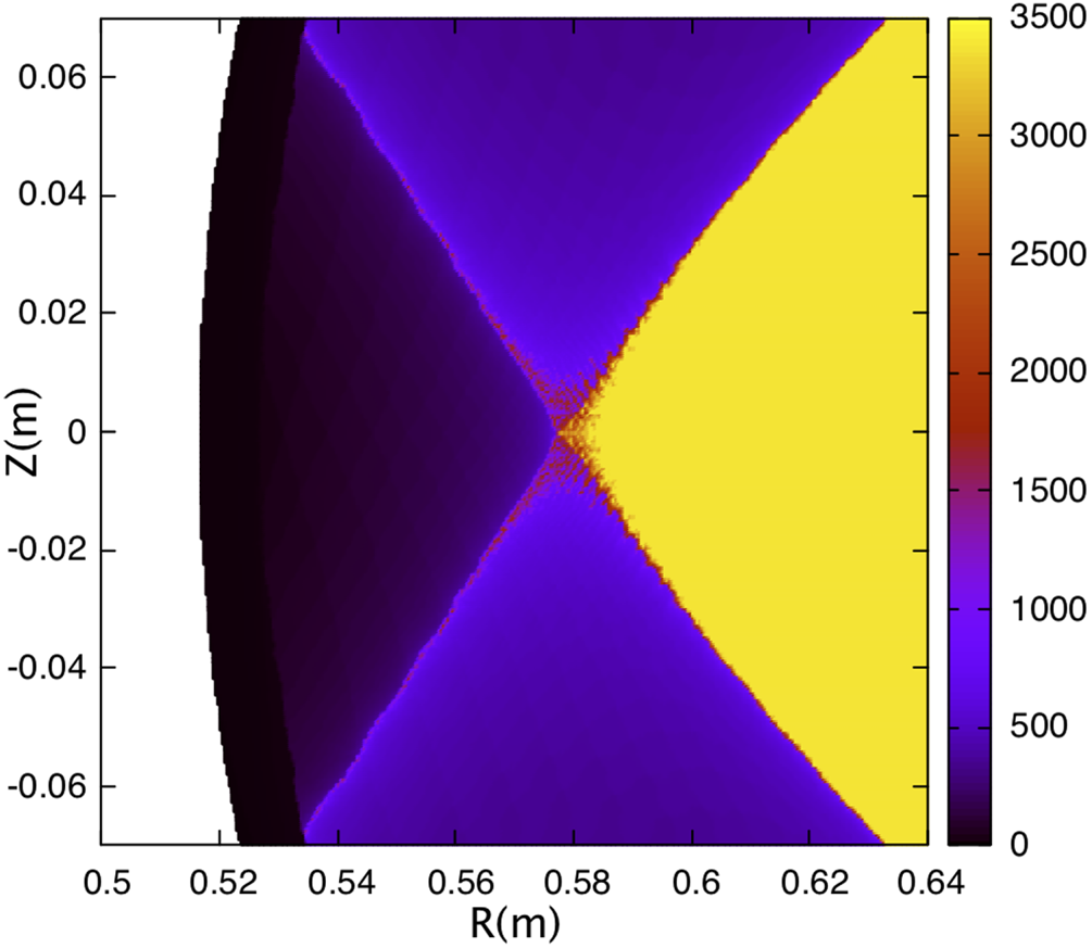
Figure 7. Distribution of connection length near one of the X points in the island divertor of CFQS.
The magnetic field lines located on the separatrix lines (red colour) are parts of the field lines escaping from the core confinement region (yellow colour) through the separatrix interface between the core and the island region. These field lines finally hit the wall (shown by the boundary of the black coloured area) at the left side of the figure. The position of this strike point moves as the position of the island changes. When the rotational transform value is shifted with the change of the current in the auxiliary toroidal coils by 2 %, the position of the strike point moves approximately 1.5 cm along the wall. This sensitivity of the island position is within the controllability of the rotational transform with the auxiliary toroidal coil.
Because the rotational transform of the island divertor region is 0.4 (n = 2/m = 5), the islands shown in figure 4 are connected together. In other words, this island flux is a single flux. Thus particles and heat flux transferred from the core confinement region to the divertor region can be removed at any position in the torus. Because the space between the plasma and the wall is very narrow in the toroidal position of the crescent shape of the plasma (the leftmost LCMS in figure 1), we can avoid installing divertor structure at this region and take advantage of installing it where the space is larger.
4. Effect of bootstrap current
We have discussed so far the island divertor concept for CFQS based on the vacuum magnetic field produced by the external coils. Because the bootstrap current estimated from the neoclassical theory is larger for the quasi-axisymmetric stellarator compared to other types of stellarator, it is necessary to find the operation scenario of the island divertor for a plasmas with finite beta. An example of the bootstrap current calculation for CFQS has been reported in the previous paper with planned experimental parameters (Shimizu et al. Reference Shimizu, Liu, Isobe, Okamura, Nishimura, Suzuki, Xu, Zhang, Liu and Huang2018). Figure 8 shows an example of the calculated profiles of the rotational transform in the operation with finite beta value. The calculation is based on the VMEC code, which is widely used for the calculation of three-dimensional equilibria with given plasma current profile. The black line shows the profile for the vacuum equilibrium with zero beta. It is equivalent to the blue line in figure 2 plotted from the magnetic field line tracing for the vacuum field. The red line shows the rotational transform profile with the averaged beta value of 0.35 %. The bootstrap current is calculated using the BOOTSJ code (Shaing et al. Reference Shaing, Crume, Tolliver, Hirshman and van Rij1989) for the pressure profile shown by the blue curve in pascal units. This shape of the pressure profile is assumed based on the typical density and temperature profiles observed in many stellarator experiments (Shimizu et al. Reference Shimizu, Liu, Isobe, Okamura, Nishimura, Suzuki, Xu, Zhang, Liu and Huang2018). When these codes are used for calculating the rotational transform profile with bootstrap current, the reliability of the profile data in the vicinity of the magnetic axis is not good. Therefore, these line are shown by dots for that area. It passes the value of 0.4 (n = 2/m = 5) at the edge, which is expected to form islands. However, because the VMEC code assumes the existence of clear magnetic surfaces, discussions of the island structure need more advanced theoretical work using HINT, which is beyond the scope of this paper.

Figure 8. Rotational transform profiles calculated by VMEC code. The black line shows the profile for the vacuum field (zero beta). The red line shows the profile with bootstrap current calculated for a beta value of 0.35 % and the pressure profile shown by the blue curve. The green line shows an example of profile control using auxiliary toroidal field to shift up the red profile by reducing the toroidal field produced by modular coils.
The green dotted line shows an example of controllability for the rotational transform profile using an auxiliary toroidal coil. This profile is an example of applying the additional toroidal field to shift up the profile from the one with bootstrap current. In fact, the expected operation would be either shifting up or shifting down the rotational transform profile to match to the value of 0.4 in order to create an island divertor configuration for the plasma with beta value different from 0.35 %.
For such finite beta plasmas, it is necessary to make two different controls in order to create a good island divertor configuration. The first one is to adjust the rotational transform value near the plasma edge at 0.4, which is resonant to the n = 2/m = 5 islands. This control is relatively easy using an adjustable power supply for the auxiliary toroidal coils. The second one is to control the plasma pressure profile for obtaining a suitable bootstrap current profile, which produces the rotational transform profile with very low negative shear. This control would be technically difficult but could be achievable with proper heating control, which will be an important research topic in the experiments. The duration of the plasma discharge planned in the CFQS programme is 100 ms due to the limitation of the heating devices. The estimated rising time of the bootstrap current is between 20 and 100 ms depending on the collisionality. Even if a fully developed equilibrium with bootstrap current is not possible for collisionless plasmas in the strict sense, the experimental analysis for this scientific topic will be possible.
Because theoretical analysis of the island divertor configuration needs the equilibrium calculation, including island structure, a model calculation using the HINT code (Suzuki et al. Reference Suzuki, Nakajima, Watanabe, Nakamura and Hayashi2006; Suzuki Reference Suzuki2017) is now in progress and will be reported in a succeeding paper. The equilibrium calculations using VMEC for the rotational transform profiles with auxiliary toroidal coils were made for different beta values up to 1.5 % volume-averaged beta. For higher beta than 0.35 %, the auxiliary toroidal field must be positive (same polarity as the basic toroidal field) in order to decrease the rotational transform at the plasma edge down to 0.4.
5. Summary and future works
A divertor configuration design for a quasi-axisymmetric stellarator CFQS is proposed. Island divertor flux (peripheral region) surrounds the core confinement region with a clear interface of magnetic separatrix. Particles and heat emerging from the core region through the separatrix flow around in the island divertor flux and are finally absorbed by the divertor plates carefully designed on the wall. Because the magnetic structure of the island divertor is regular (very little stochasticity), precise design of the shapes and locations of divertor plates makes it possible to obtain an appropriate distribution of the heat load on the divertor plates. The connection length of divertor field lines is sufficiently long because of the small poloidal magnetic field component in the divertor region. The experimental validation of this divertor concept will be programmed in the international collaboration project between NIFS and SWJTU for CFQS experiment performed in China.
The purpose of this paper is to show the possibility of the divertor configuration in the on-going experimental program of CFQS. A number of succeeding topics are under investigation, namely, (1) studies of equilibria with finite beta, (2) effects of bootstrap current for divertor configuration, (3) plasma and neutral particle dynamics in the divertor region, and (4) MHD stability with big islands. The results of these theoretical works will be reported in succeeding papers. More important research would be to conduct real experiments. This island divertor design is very useful because it will be implemented in the real device that is under construction.
Acknowledgements
This work was partly supported by the NIFS Collaboration Research program (NIFS17KBAP034, NIFS18KBAP041, NIFS20KNSP010) and the National Science Foundation of China under Grant No. 11820101004.
Editor Per Helander thanks the referees for their advice in evaluating this article.


 Open access