
Abstract
Structural power composites are multifunctional materials with simultaneous load bearing and energy storing functionality. This is made possible due to carbon fibers' ability to act not only as structural reinforcement materials, but also as electrode components. A crucial component of structural power composites is the structural electrolyte that is required to have both high stiffness and high ionic conductivity. To explore microstructure properties that bear optimal bifunctional performance a procedure is presented to generate various classes of synthetic microstructures with a wide span of properties for computer simulation. The effective properties of the generated artificial structural electrolytes are obtained via virtual material testing and compared with experimentally obtained data. Ultimately, a microstructure class with very good bifunctional properties is identified.
Export citation and abstract BibTeX RIS
1. Introduction
Carbon fibers are widely used as structural reinforcement materials [1]. By utilizing their capacity to intercalate lithium ions, they can also be used as electrode components in structural batteries [2–4]. Furthermore, it has been shown that reinforcing carbon fibers with carbon aerogel increases the carbon fibers' surface area which makes them suitable as electrodes in structural supercapacitors [5]. Both the structural battery and the structural supercapacitor are frequently called structural power composites due to their simultaneous load bearing and energy storing functionalities [6]. As a result of their multifunctionality, it is possible to achieve significant weight and volume savings as compared to the use of their monofunctional subsystems individually [6–8].
A major challenge in the field of structural power composites is the design and performance assessment of structural electrolytes. It is required of the structural electrolyte to be ionically conductive, while providing high mechanical integrity [6]. One typical composition of the structural electrolyte consists of liquid electrolyte and polymer matrix [9]. However, simply curing these constituents together often results in gel polymer electrolytes with limited load carrying capacity [10–13]. Currently, two promising methods for developing structural electrolytes utilize high internal phase emulsion (HIPE) templating and polymerization induced phase separation (PIPS) [14–19]. The primary reason for their success is because both approaches can produce in-situ filled porous polymer systems with bicontinuous microstructures, i.e. an intermingled liquid-solid system with superior multifunctional performance [15]. While the continuous solid phase contributes to high mechanical performance, the liquid phase provides high ionic conductivity. It is also possible to achieve such bicontinuous systems by first forming a porous neat polymer sample that is later filled with a liquid electrolyte [20]. Shirshova et al and Yu et al developed one of the earliest bicontinuous structural electrolytes, where the solid phase provides high mechanical integrity and the liquid phase provides high ionic conductivity [17, 21, 22]. Later on, Ihrner et al successfully designed the first bicontinuous structural battery electrolyte (SBE) and produced a carbon fiber lamina half-cell that allows for electrochemical cycling [18]. Based on this, Schneider and coworkers improved the SBE's processability by exploiting heat curing instead of UV-curing [19].
In the existing literature, the mechanical and electrochemical performance of structural electrolytes has mainly been assessed by experimental investigations, whereas merely a few studies treat the modeling aspects of structural electrolytes [23, 24]. In order to reduce the number of experiments and advance structural electrolyte research, new design tools are needed. We aim at using numerical simulations to evaluate the effective stiffness and effective ionic conductivity of artificial microstructures for structural electrolytes. By numerically generating structural electrolytes it becomes possible to explore microstructures of various shapes and porosities. The goal is to find electrolyte architectures that exhibit high multifunctional performance which can be evaluated by virtual material testing. Numerical results are compared with experimental data for validation. Ultimately, a class of microstructures with very good bifunctional performance is identified.
2. Microporous bicontinuous structural electrolytes
Electrolytes based on porous polymer systems for batteries and supercapacitors are well documented in the literature. They possess a wide range of properties depending on their composition and synthesis method, and some of these electrolytes show great potential to be used as structural electrolytes in structural power composites. As previously mentioned, the two main methods for synthesis of in-situ filled porous polymer electrolytes are HIPE templating and PIPS. The HIPE templating approach requires presence of at least two immiscible phases that upon mixing forms an emulsion. Polymerization of the internal continuous phase occurs around emulsion droplets and results in the formation of highly porous polymers. The PIPS method utilizes the fact that solubility parameters change when monomers transform to a polymer [25]. By using components with specific solubility parameters, they can initially be fully miscible, but totally immiscible after the monomers transform into polymers. This enables in-situ curing of monomers in presence of a liquid electrolyte for structural electrolyte formation [26, 27], which is an attractive method from a manufacturing point of view [18]. Several example electrolyte systems based on both HIPE templating and PIPS are shown in figure 1.
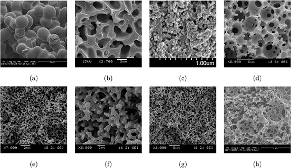
Figure 1. SEM images of the solid polymer matrix with different structures; (a) 60DGEBA, (b) 50MTM57/2.3 M_1PC [17], (c) AB/0.653 [18], (d) polyHIPE [16], (e) 50VTM266/2.3 M [21], (f) 30MVR444/2.3 M [21], (g) 40MVR444/2.3 M [21], and (h) polyMIPE.
Download figure:
Standard image High-resolution imageThe corresponding material parameters of the electrolytes in figure 1 are presented in table 1. The intrinsic parameters E and M are the Young's modulus of the bulk polymer and the ionic conductivity of the neat liquid electrolyte that saturates the open pore system. For all systems, the Poisson ratio is chosen as ν = 0.33 [28]. These intrinsic parameters serve as input data for the simulations. The effective properties  and
and  refer to the overall properties of the structural electrolyte with porosity φ, and are used for validation of simulation results. We measured the effective properties by conducting experimental testing procedures in the same fashion as described by Shirshova et al [16, 17, 21] The mechanical properties were characterized by three-point-bending and compression tests, while the ionic conductivity was measured using dielectric spectroscopy. The porosities were estimated by drying the samples and measuring the mass fraction of dry and saturated, i.e. liquid filled, sample. Lastly, the intrinsic properties were taken from the constituents' material data sheet.
Table 1. Intrinsic and effective material properties of structural electrolytes and their constituents.
| Intrinsic properties | Effective properties | ||||||
|---|---|---|---|---|---|---|---|
| Figure 1 | Structural electrolyte | E (GPa) | M (mS cm−1) |  (GPa) (GPa) |
 (mS cm−1) (mS cm−1) |
φ (%) | |
| (c) | AB/0.65 | — | — | — | 0.19 [18] | — | |
| (a) | 60DGEBA | 3.00 | 3.15 | 0.15 | 1.22 | 49 | |
| (b) | 50MTM57/2.3 M_1PC | 2.73 | 9.8 | 0.90 [17] | 0.15 [17] | 54 | |
| (e) | 50VTM266/2.3 M | 2.66 | 9.8 | 0.66 [21] | 0.015 [21] | 44 | |
| (f) | 30MVR444/2.3 M | 3.22 | 9.8 | 0.18 [21] | 0.8 [21] | 65 | |
| (g) | 40MVR444/2.3 M | 3.22 | 9.8 | 0.49 [21] | 0.07 [21] | 54 | |
| (d) | polyHIPE | — | — | 0.062 | — | 80 | |
| (h) | polyMIPE | 3.00 | 7.8 | 0.20 | 1.9 | 50 | |
3. Numerical generation of microstructures
To account for the effects of micro-heterogeneities in the structural electrolyte microstructure, we aim at resolving the problem on a Representative Volume Element (RVE). For the microstructures presented in figure 1, no 3D data obtained from e.g. FIB (focused ion beam) SEM imaging is available. Hence, we numerically generate various classes of random electrolyte microstructures for virtual testing. Note that the aim is not to mimic each and every microstructure in the SEM images in figure 1. The goal is just to generate some classes of microstructures that seem realistic based on the collection of SEM images that are available. An extensive overview about generation of random microstructures with emphasis on bicontinuous mixtures is available in Bargmann et al [29, 30] For this study, we investigate the bifunctional performance of bead, trabecular and imperfect trabecular structures. Examples are shown in figure 2. Subsequently, we briefly document the generation techniques.

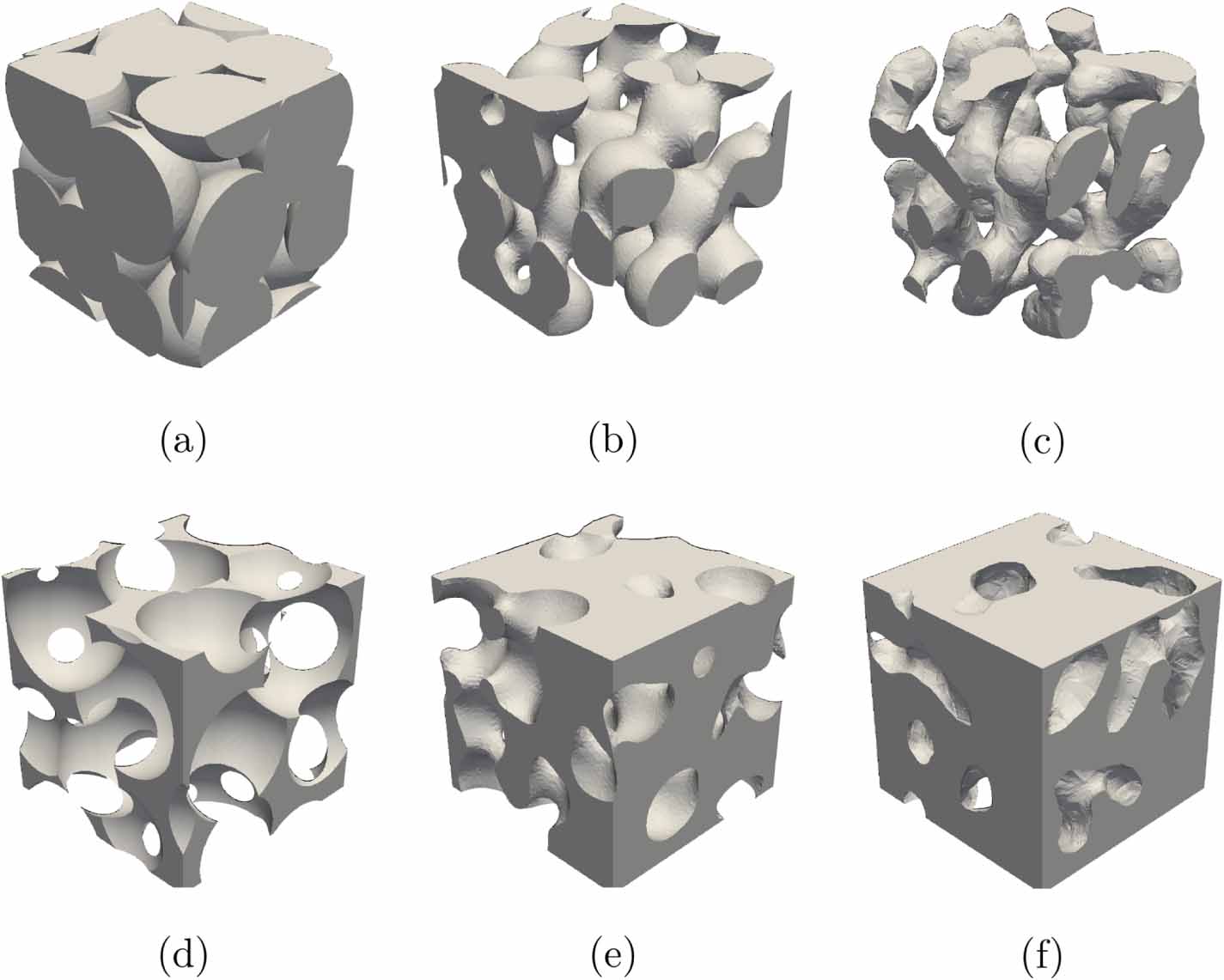
Figure 2. Solid polymer matrix of various artificially generated microstructures; (a) bead, (b) trabecular, (c) imperfect trabecular, (d) inverse bead, (e) inverse trabecular, and (f) inverse imperfect trabecular.
Download figure:
Standard image High-resolution imageBead structures: Starting point to generate bead structures is a dense sphere packing exploiting the Lubachevsky–Stillinger algorithm [31, 32]. For this study, we used monodisperse dense sphere packings, but more complex particle size distributions are possible. In a second step, the radius of the spheres is increased such that the spheres overlap. The amount of overlap controls the porosity of the resulting structure within certain limits. The resulting 3D microstructures are porous and bicontinuous; resembling a structure built of sintered beads, see figure 2(a).
Trabecular structures: We generate stochastic trabecular structures by employing Voronoi tesselation [33]. This allows us to partition the RVE volume into polyhedral cells which serve as input geometry for solving a linear heat equation problem in the RVE. Here, the edges of the Voronoi cells are treated as heat sources, while the centers of the cells are used as heat sinks. From the resulting 3D temperature distribution, iso-surfaces at chosen temperature levels can be extracted and converted into 3D solid structures, see figure 2(b). The resulting structures, called trabecular, are bicontinuous with highly connected pore channels. The porosity of the structure can be controlled by varying the temperature level.
Imperfect trabecular structures: We investigate a third family of microstructures that is generated by simulating the spinodal decomposition of a mixture consisting of two constituents. For this, we solve the Cahn-Hilliard equation [34, 35]. The resulting microstructures, see e.g. figure 2(c), are of trabecular type. However, the pore channels are not fully connected, and thus only partly bicontinuous. One may observe dead-end channels as well as some unconnected pores. Therefore, we coin the name imperfect trabecular structures. The porosity of the resulting microstructures can be controlled by adjusting the input parameters to the Cahn-Hilliard equation.
Inverted microstructures: We are able to reinterpret all microstructures by exchanging the solid and the pore channel domain, i.e. inverting the structures, see figures 2(d)–(f). This gives rise to the inverted bead structure, the inverted trabecular structure and the inverted imperfect trabecular structure.
4. Virtual testing of the bifunctional performance
We employ virtual testing to derive the relevant effective material properties that characterize the macroscopic response of the heterogeneous sub-scale RVE problem [36]. Hence, computer simulation of the bifunctional properties is carried out on the RVE domain  , where all quantities and operators with the box notation
  are associated with the sub-scale RVE. For this section, we introduce RVE volume averaging as

4.1. Elastic stiffness
We assume that the mechanical resistance from the liquid phase in the pore channels can be ignored when the structural electrolyte is loaded, i.e. the pore pressure vanishes and the structural electrolyte is considered as a drained system which corresponds to the conditions for measuring the stiffness of a dried sample in the laboratory. Linear elasticity in the solid domain is defined as

with the stress  , the strain
  , and the isotropic stiffness tensor
  . The elastic parameters are chosen as Young's modulus E and Poisson's ratio ν. Note that, due to the drained situation,
  in the pore space. While the elastic stiffness tensor
  in (2) represents the stiffness of the bulk material, our aim is to compute the effective elasticity tensor
  of the porous solid phase via the macroscopic relation

with the effective strain  and the effective stress
  representing the overall properties of the porous RVE. In order to compute
  , we first introduce the prolongation of the macroscopic strain
  onto the RVE surface via the relation

Here,  is the position vector in the RVE,
  is the displacement field, and
  is a periodic fluctuation [36]. We are now in the position to discretize the solid domain and to solve the linear boundary value problem with the Finite Element Method imposing the six independent loading cases of the symmetric macroscopic strain tensor
  , k, l = 1, 2, 3. Finally, the components
  , i, j, k, l = 1, 2, 3, of the macroscopic elasticity tensor can be computed from the macroscopic response
  of the RVE under the unit strain
  via the relation

4.2. Ionic conductivity
We assume that the ionic transport in the solid polymer matrix material can be ignored, i.e. it takes place only in the liquid phase occupying the continuous pore channel domain. Furthermore, the transport mechanisms are restricted to diffusion and migration due to an electric field, i.e. convection is ignored. Hence, we assume a Fickian constitutive relation [37]

where  is the ion mass flux,
  is the gradient of the electro-chemical potential µ, and M is the isotropic ionic conductivity of the electrolyte. The electro-chemical potential can be decomposed into the chemical potential
  and the electric potential ϕ via the definition
  , where F is Faraday's constant and z is the charge number for Li-ions (z = +1 for Li+). Note that we also make the model assumption that the ionic conductivity is the same whether it is the electric or the chemical potential that is the driving force. In complete analogy with the elastic problem, our aim is to compute the effective ionic conductivity
  via the macroscopic relation

where we introduce the overall gradient of the electro-chemical potential  and the averaged ionic mass flux
  . Note that, due to the heterogeneous distribution of the pore space in the RVE,
  might be anisotropic in contrast to the isotropic conductivity M of the neat electrolyte. To compute
  , we apply the macroscopic gradient
  on the RVE surface via the relation

with the periodic fluctuation  . We discretize the pore channel domain and solve the linear boundary value problem with the Finite Element Method imposing the three independent loading cases of the gradient vector
  , n = 1, 2, 3. The components
  , m, n = 1, 2, 3, of the overall conductivity tensor can be computed from the RVE response
  of the RVE under the unit gradient
  of the electro-chemical potential via the relation

5. Results and discussion
The effective bulk modulus  and the effective shear modulus
  , which give the effective Young's modulus
  , and the effective ionic conductivity
  were computed for a wide range of porosities φ. As mentioned above, the computed overall material properties might only be approximately isotropic. We, therefore, compute quasi-isotropic values for
  and
and  as
as


Hence, we obtain Young's modulus as  . Moreover, we compute the quasi-isotropic ionic conductivity of the structures as

The results are plotted in figure 3 versus φ for the different types of artificial microstructures. For comparison, we plot the material properties as computed analytically from an arithmetic mixture rule (Voigt-Taylor upper bound) as well as the experimental data from table 1.
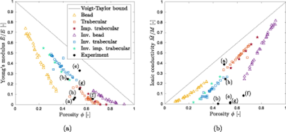
Figure 3. Normalized effective properties for different microstructures versus porosity: (a) effective Young's modulus, (b) effective ionic conductivity. The letters in the figure refer to the SEM images in figure 1.
Download figure:
Standard image High-resolution imageWe observe that the different types of stochastic microstructures can be produced for a wide porosity range. Overall, the bead structures tend to lower porosities (ca. 0.1 ≤ φ ≤ 0.35) than the trabecular structures (ca. 0.45 ≤ φ ≤ 0.7). The inverse structures behave accordingly. Moreover, increasing porosity results in decreasing stiffness and increasing ionic conductivity. For all microstructure types, the properties scale approximately linearly with the porosity. At φ = 0.5, the Voigt-Taylor bound overestimates the effective properties computed from the stochastic microstructures by approximately 40%–100%. Note that the experimental data are found in a much more narrow porosity band (0.44 ≤ φ ≤ 0.65).
The predicted stiffness of the synthetic microstructure seem to be within the same order of magnitude as the measured stiffness of the real electrolyte systems (b), (f) and (g), while (a), (e), and (h) deviate slightly from the trend. In contrast, the agreement for ionic conductivity is very poor for most of the structures. This may be explained by the fact that our simulations of ionic conductivity are based on Fickian diffusion. However, the experimental data has been produced for ionic liquids as used for supercapacitors [17, 21]. Ionic liquids are known to exhibit a more complex diffusion behavior than Fickian diffusion due to continuous ion pairing. This perturbs the diffusion path such that the ion can no longer find the shortest path toward the electrode surface. Moreover, ionic liquids are composed of large ions which might block the electroactive species [38, 39]. All of this might lead to the, compared to the simulations, lower conductivity in the experimental results. Further investigation is needed. By contrast, Fickian diffusion is well-accepted for conventional electrolytes used in structural batteries and, therefore, employed in this study. However, experimental data for validation is lacking.
Finally, we present the results in a fashion that can be used as a guideline on how to choose the microstructure to obtain optimal bifunctional performance. The trade-off between  and
and  is shown in figure 4 including the Voigt-Taylor upper bound and the experimental data. We can conclude that the synthetic bead structures as well as their inverted counterparts tend to a very good performance in one effective property whilst the performance in the second effective property is poor. A performance that is equally good for both properties is observed for trabecular and imperfect trabecular structures, and their inverse counterparts at φ ≈ 0.5. An example for such a structure with very good bifunctional properties is the one displayed in figure 2(b). Moreover, it can be observed in figure 4 that the simulation data is in good agreement with the multifunctional performance of the experimental data for electrolyte systems (a) and (h).

Figure 4. Trade-off between stiffness and ionic conductivity. The letters in the figure refer to the SEM images in figure 1.
Download figure:
Standard image High-resolution image
6. Conclusion
This investigation aims at assessing the bifunctional performance of structural electrolytes in terms of assumed linear constitutive relations for stiffness and ionic conductivity and neglect of any coupling between these characteristics. The computational results can serve as virtual experimental data that are valuable complements to laboratory data, in particular since computations are much more inexpensive. It is noted that the investigated microstructural topologies are realizable over wide porosity ranges yet forming a bicontinuous system.
Although quite limited physical experimental data are available, they indicate that the predicted effective stiffness is in the correct order of magnitude. The deviation between the experimental data and the simulations of the effective ionic conductivity might be explained by the more complex diffusion behavior of ionic liquids as used for the laboratory experiments while Fickian diffusion, which is common for electrolytes in structural batteries, is used for the simulations.
It is important to remark that the introduced generation techniques are pseudo-physical and do not aim at simulating the true curing process of the structural electrolyte systems. However, due to lack of 3D data of electrolyte microstructures, these techniques allow us to construct a wide range of bicontinuous topologies. In turn, this shall assist chemists to design polymer microstructures with the desired optimal bifunctional properties.
Conflicts of interest
There are no conflicts to declare.
Acknowledgments
LA and KR acknowledge funding from the European Commission via the Clean Sky II research project no. 738085, LA also acknowledges funding from USAF via AFOSR Grant FA9550-17-1-0338. LA and NS acknowledge funding from the EU as part of the FP7 project "Storage" (Grant Agreement No.234236). Also, NS acknowledge funding from Engineering and Physical Sciences Research Council (EPSRC) UK grant EP/P007465/1 and EP/R021503/1 and help with 60DGEBA and polyMIPE samples preparation and characterisation by Ms B Clough, Mr J Dowel and Dr W Quan.
Footnotes
- 1
Reproduced from Ihrner et al with permission from the Royal Society of Chemistry. Used under CC BY/cropped [18].