
Abstract
In this paper, fluid flow and heat transfer characteristics in a channel equipped with two isothermal diamond blocks such as blocks filled with PCM's (during phase changing) to find out the optimum state in fluid flow and heat transfer behavior have been investigated. Different Reynolds and Prandtl numbers and different geometrical parameters such as the block size and location have been studied. The governing equations, including continuity, momentum, and energy, have been solved by the SIMPLE method. Results show that an increase in the block size and an increase in the distance of the blocks from the walls of the channel increases the friction factor and bulk temperature changing. Also, the ratio of the bulk temperature changes to friction factor for different Reynolds and Prandtl numbers shows an optimum state at a = 0.11 and 0.125 < b < 0.15. The results of this study could be used in designing air-conditioning systems or in microchannels equipped by blocks or ribs to enhance the heat transfer rate.
Export citation and abstract BibTeX RIS
Nomenclature
| a | non-dimensional size of the blocks |
| A | area of the block image perpendicular to the stream direction, m2 |
| b | non-dimensional distance of the blocks from walls |
| Cp | specific heat capacity, J.kg−1.K−1 |
| dTb | non-dimensional bulk temperature change |
| EC | effective coefficient |
| f | friction factor |
| FD | the drag force, N |
| H | height of the channel, m |
| J | Jacobian of the coordinate transformation |
| k | thermal conductivity, W.m−1.K−1 |
| L | non-dimensional channel length |
| LC | non-dimensional circulation length |

|
flow mass rate, kg.s−1 |
| p, P | non-dimensional and dimensional pressure, Pa |
| Pe | Peclet number |
| Pr | Prandtl number |

|
heat transfer rate, W |

|
parameters defined in equation (8) |
| Re | Reynolds number |
| T | non-dimensional temperature |
| U, V | velocity component in x, y directions, m.s−1 |
| u, v | non-dimensional velocity component in x, y directions |
| X, Y | x, y coordinate, m |
| x, y | non-dimensional x, y coordinate |

|
general variable (u, v) in equation (6), m.s−1 |

|
viscosity, Pa.sec |

|
density, kg.m−3 |

|
temperature, K |

|
curvilinear coordinate components |
| C | contravariant velocities |
| b | fluid bulk temperature |
| f | Fluid |
| in | Inlet |
1. Introduction
Using phase change material (PCM) is a passive method in the cooling processes. One of the applications of this method is using ice blocks in air conditioning. At midnight when the load of the city electricity consumption is low, the chiller can be turned on to produce ice in the blocks. In the morning, just by turning on the fan (while the chiller is off), the ambient air can be cooled by passing on the ice blocks to enter fresh and cold air to buildings. Another application of using ribs or blocks is increasing the heat transfer rate in microchannels. If the blocks are produced from metals with a high thermal conduction coefficient, their temperature can be constant, as reported by Datta et al [1]. Since the laminar flows have a low heat transfer rate in comparison with turbulent flow, researchers are using ribs on walls or blocks in the middle of the channel to improve the heat transfer behavior.
Datta et al [1] investigated laminar flow conjugated heat transfer, including conduction in body and convection mechanism in the flow in a rectangular microchannel with trapezoidal cavities and Ribs considering the entropy generation and thermal performance. They investigated four types of ribs and arrangement and showed that the channel with diamond ribs has the maximum thermal performance. This result has been confirmed by Chai et al [2]. Li et al [3] studied flow and heat transfer characteristics in rectangular cooling channels with strip slit in ribs on the wall of a channel with aspect ratio of 4:1. They suggested that using ribs is a beneficial way to increase heat transfer of cooling channels. Laminar thermal and fluid flow characteristics in tubes with sinusoidal ribs with different pitches and sizes were studied numerically by Du et al [4]. The Reynolds number was 400 to 1800. Their results showed an increase in Nusselt number up to 4.89 times in comparison with smooth pipes. Wang et al [5] studied laminar fluid flow and heat transfer characteristics of a microchannel heat sink with shortened ribs in a parallel and staggered arrangement. In their study, the Reynolds number was between 100 and 1000. They found that for an arrangement, the overall thermal enhancement factor is maximum. Pressure drop and heat transfer rate in rectangular duct equipped by hybrid ribs on the bottom wall was studied by Alfarawi et al [6] experimentally. The geometry of the ribs was rectangular and semi-circular and hybrid of them. They reported that heat transfer enhancement in the presence of ribs could be exceeded to 2.14 times more than that for channels without ribs. Heat transfer and friction factor of fully developed turbulent flow in the divergent channel with ribs on the wall has been investigated by Lee et al [7]. They studied four different angles of ribs and showed that the 90° angle leads to maximum thermal performance. Gu et al [8] simulated flow and heat transfer over an obstacle in a channel numerically. They used finite volume formulation. The working fluid was air. Their results reported a 10% increase in Nusselt number on the heated wall. Heydari and Kermani [9] studied nanofluid heat transfer in a channel with different ribs number on one wall numerically. The flow region was laminar with Reynolds number less than 1500. They showed that nanofluid in the presence of the ribs could increase the Nusselt number up to 60%. Lei et al [10] studied thermal and hydraulic characteristics of laminar flow in a microchannel with fan-shaped ribs on sidewalls. In this work, the Reynolds number changes from 187 to 715. In one type of ribs, a 101% augmentation in Nusselt number has been reported.
The thermal and hydrodynamic performance of a brass mesh in a vertical channel for three different porosities has been investigated by Kurian et al [11] experimentally. They studied meshes with three different porosities and showed that using mesh blocks is a suitable method to increase the heat transfer rate. Rostami et al [12] investigated the effect of geometrical parameters in the wavy microchannels with a Reynolds number less than 250. They found an optimum geometrical parameter, which leads to maximum heat transfer and minimum pressure drop.
The existing literature focused on equipping channels by ribs on the walls or blocks in the middle of the channel. But the lack of studies on the effect of the blocks locations is obvious. In our previous work [13], we studied this problem for square shape blocks, and found the optimum size and location. To develop the work and improve the performance of the other block shapes, a diamond block has been selected to find out the optimum state. In the present study, by changing the location and size of the isotherm diamond blocks, the optimum size and position in view point of heat transfer and fluid flow at different Reynolds and Prandtl number are discussed.
2. Governing equations and boundary conditions
The physical domain of a channel with two isothermal diamond blocks is shown in figure 1. Because of the presence of ribs or blocks in channel or waviness in walls, the flow region may change from laminar to turbulent in a Reynolds number under 2300 [14]. Therefore, to hold the regime of the flow in the laminar region and to avoid a significant pressure drop, Reynolds number has been chosen under 700. The Prandtl numbers of the working fluid are assumed to be 0.7, 1.4, and 3. Geometrical parameters, including the location of the block (b) and the dimension (a), varied to find the optimum state in heat transfer rate and pressure drop. The length of the channel has been selected such a way the flow be fully developed again at the outlet boundary.
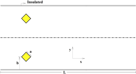
Figure 1. The physical domain of the channel and the blocks.
Download figure:
Standard image High-resolution imageDue to the shape of the blocks, a body fitted mesh has been employed (figure 2). Then, the governing equations for a two-dimensional incompressible laminar flow, including continuity, momentum, and energy, are transformed from the Cartesian coordinate system (x, y) to the curvilinear coordinate system 

Figure 2. Generated mesh for half of the channel.
Download figure:
Standard image High-resolution imageBy introducing the following non-dimensional parameters,

The flow is laminar, steady-state, and two dimensional. Then the governing equations can be expressed as follows [15, 16],
2.1. Continuity

with the definitions

where 'J' is the Jacobian of the coordinate transformation and is equal to the area of each cell in figure 1.

and

2.2. Momentum

where  is 'u' and 'v' and

Also,

2.3. Energy

2.4. Boundary conditions
Because of symmetry, half of the field (figure 1) has been selected as solution domain. As shown in figure 2, the selected domain is divided into two sections. The first section begins from the lower wall of the channel to the centerline of the block, and the second section begins from this centerline of the block to the symmetric line of the channel. Results for the top edge of the first section were used as the lower boundary condition of the second section, and the solution of the lower boundary of the second part was used as the upper boundary condition for the first section.
On the channel and block walls, for the velocity components, no-slip conditions have been applied. The channel wall is insulated, and the block walls are isotherm. Then for the first section, on the wall,

and at the symmetric line (upper boundary of the second part of the solution domain)

On the block walls, no-slip condition for velocity components is applied and based on the defined dimensionless temperature, the block walls temperature is zero,

Also, the inlet temperature is unit. It is supposed that the velocity profile id fully developed before arriving at the inlet boundary and will be fully developed again at the outlet boundary (far from downstream from the block). Based on these explanations, the boundary conditions at inlet and outlet boundaries, are expressed as follows,

3. Numerical method
The finite volume method on a collocated grid is used to solve the governing. Avoiding pressure independency of each cell from the pressure amount of the neighbor grids, the interpolation of the Rhie and Chow [17] has been applied. For convective terms in momentum and energy equations, the HYBRID differencing [18] is used. Finally, the SIMPLE method [19] used to solve the discretized algebraic equations. As shown in figure 2, the grid points are created with a manner to be compressed and closer to the walls. The discretized equations were solved using line by line method for both sections.
To be sure that the results are independent of the grid size, it has been performed and the mesh with  grid points is chosen. The grid independency has been shown in table 1 based on equation (22). The number of point, in the 'y' direction in each section, has been used proportional to the location of the block.
Table 1. Grid Independency.
| Grid | f | error% | dTb | error% |
|---|---|---|---|---|

|
0.0780 | 4.2 | 0.0790 | 5.95 |

|
0.0806 | 1 | 0.0824 | 1.9 |

|
0.0814 | — | 0.0840 | — |
To verify the results, the velocity profile at the outlet boundary obtained by the code was adapted on the analytical solution. This verification has been shown in our previous work [13]. Also, for the square block located in the channel center the circulation length of based on the Reynolds number has been compared with Breuer et al [20] in figure 3.
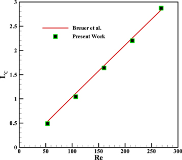
Figure 3. Circulation length in different Reynolds number.
Download figure:
Standard image High-resolution imageResults in the next section are including pressure drop and change in fluid bulk temperature based on the following formulas. The pressure drop is obtained by

By rearranging it and using dimensionless parameters

by defining the bulk temperature as follows

and using the non-dimensional parameters (equation (1))

The heat transfer rate from the working fluid to the block can be calculated by the bulk temperature,

Where  is the mass flow rate and is equal to
  Also, using the non-dimensional parameters (equation (1))

Also,  then
then

Finally,

Then, the  determines the heat transfer rate from fluid to the block.
4. Results and discussions
Generated recirculation zones in different states including, different geometrical parameters and different Reynolds numbers, have been illustrated in figures 3–5 by streamlines. It is obvious that these studied parameters have significant effects on the shape of the streamlines and the size of recirculation zones.
Streamlines for different Reynolds numbers (500 and 700) at b = 0.25 and a = 0.11, illustrated in figure 4. The shapes of the recirculation zones are not symmetric. Because the bottom part and the top part of the block are exposed to different flow speeds. It is evident, that the recirculation zones are bigger in higher Reynolds numbers, and these recirculation zones are more extended in higher Reynolds numbers.
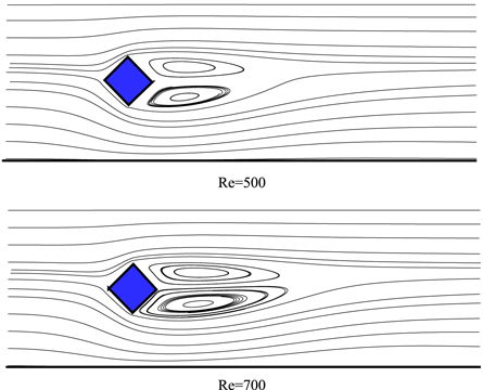
Figure 4. Streamlines at b = 0.25 and a = 0.11 for different Reynolds numbers.
Download figure:
Standard image High-resolution imageFigure 5 shows the streamlines for different location (b) and a = 0.1 at Re = 700. In lower 'b', there is no recirculation zone behind the block. But there is a large recirculation zone after the block and near the channel wall. By increase 'b' two recirculation zones will appear behind the blocks and their size are greater in higher 'b', because of facing higher axial velocity.

Figure 5. Streamlines for Re = 700 and a = 0.1 at different locations (b).
Download figure:
Standard image High-resolution imageFigure 6 shows the streamlines for different sizes (a = 0.08 and 0.12) at Re = 700 and b = 0.2. Increasing the block size has a sensetive effect on the flow field. So that, the size of the recirculation zones is greater in the bigger size of the block.

Figure 6. Streamlines for Re = 700 and b = 0.2 at different sizes (a).
Download figure:
Standard image High-resolution imageThe effects of geometrical parameters, Reynolds numbers and Prandtl number on the temperature field has been depicted in figures 7–9 by temperature contours.
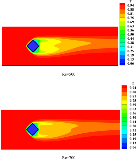
Figure 7. Temperature contours for Pr = 1.4, b = 0.25 and a = 0.11 in different Reynolds numbers.
Download figure:
Standard image High-resolution image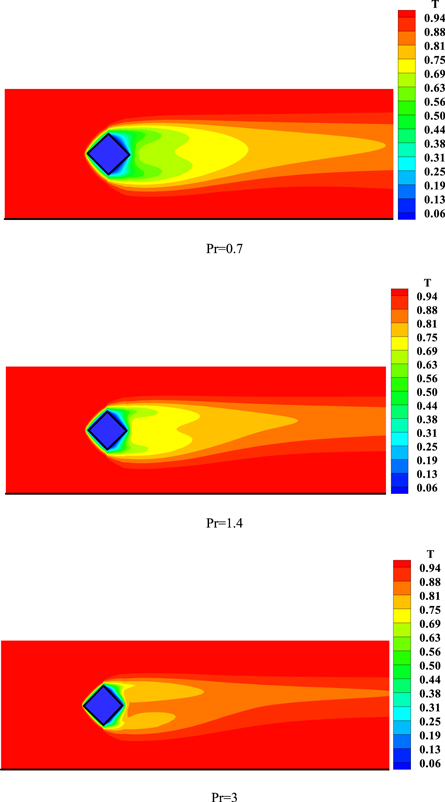
Figure 8. Temperature contours for Re = 500, b = 0.25 and a = 0.11 in different Prandtl numbers.
Download figure:
Standard image High-resolution image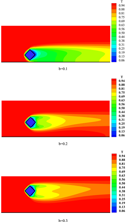
Figure 9. Temperature contours for Re = 700, Pr = 0.7 and a = 0.1 at different locations (b).
Download figure:
Standard image High-resolution imageThe effect of flow field and recirculation zones on the temperature contours has been shown in figure 7 for different Reynolds numbers at b = 0.25 and a = 0.11. It is clear that at low Reynolds numbers, in comparison with convective terms in the energy equation, the diffusion term has more effect on the temperature field. In the recirculation zones the mechanism of heat transfer is diffusion. On the other hand, the temperature of a part of the fluid which has been trapped in the recirculation zones, affected by the right side of the block. It will affect the temperature of the mainstream by diffusion mechanism.
Prandtl number appears in equation (9) in the diffusion terms. By increasing this number, the effects of these diffusion terms on heat transfer will reduced. Effects of Prandtl number on temperature contour is shown in figure 8. This figure shows that by increasing the Prandtl number, the thermal boundary layer on the left walls of the block will be thinner.
Figure 9 shows the temperature contours for different locations (b) at Re = 700 and a = 0.1. For block near the wall, according to figure 5, the recirculation has a sensitive effect on the temperature contours. Because of low velocity and great recirculation zone near the wall of the channel, the mechanism of heat transfer in this zone is diffusion. By increase distance of the block from the wall (b), temperature contours will change, and convective terms in energy equation (equation (9)) play more effective roles.
The temperature contours for different sizes (a) at Re = 700 and b = 0.2 is shown in figure 10. It is clear that the size of the block has a significant effect on the temperature contours. By an increase in the block size, the mixing in fluid and heat transfer surface increases, and it leads to an increase in heat transfer rate.

Figure 10. Temperature contours for Re = 500, Pr = 1.4 and b = 0.2 at different sizes (a).
Download figure:
Standard image High-resolution imageFigure 11 shows the friction factor versus 'b' for various 'a' and different Reynolds number. It is shown that the friction factor increases with the block distance from the wall. it related to the magnitude of the velocity of the fluid which impact to the left walls of the block. In other words, the reason behind increased block friction by increasing the distance from wall is exposing of the block to higher flow velocities. This velocity has higher magnitude in a bigger 'b'. Also, in a fixed value of 'b', the friction factor increases by the size of the block. Because by increasing the block dimensions the drag force to the block increases.

Figure 11. Friction factor for different 'a' versus 'b'.
Download figure:
Standard image High-resolution imageFigure 12 shows the temperature variations for different 'a' versus 'b' in different Reynolds number. Such as the pressure drop, the temperature drops increases with the size of the block and the distance of the blocks from channel wall.
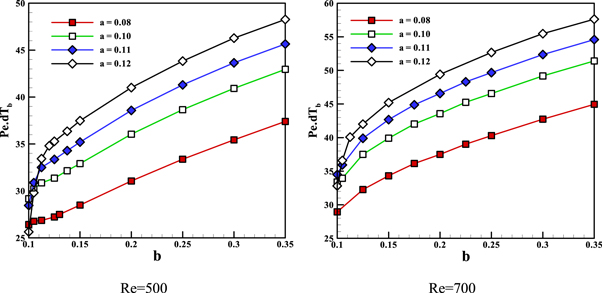
Figure 12. Bulk temperature variations for Pr = 1.4 at different 'a' versus 'b'.
Download figure:
Standard image High-resolution imageAs shown in figures 11 and 12, by increasing the block distance from the wall and its size, the friction factor and temperature drop will increase. In convective heat transfer mechanism, heat transfer increasing is desirable but friction factor increasing is not desirable. On the other hand, the complicated nature of flow and heat transfer mechanism around the block and their nonlinear governing equations (equations (2)–(9)) make it almost impossible to predict the flow behaviors. As shown in figures 11 and 12, the friction factor and temperature variation have different changing with 'b'. Then based on the Reynolds analogy [21] to pay attention to the both parameters, it is better to define the 'effective coefficient' or 'EC'. This parameter is the temperature drop to the friction factor ratio, and is introduced in equation (22).

Figure 13 shows the effective coefficient for Re = 500 for different 'a' versus 'b'. It is clear that the maximum value of EC occurs at b = 0.125 for Pr = 0.7 and 1.4, and at b = 0.15 for Pr = 3. For all cases, the maximum EC increases with the block size until a = 0.11, but for the greater sizes, the EC decreases. Then for Re = 500 the optimum situation is a = 0.11 and b = 0.125 for Pr = 0.7 and 1.4 and b = 0.15 for Pr = 3.
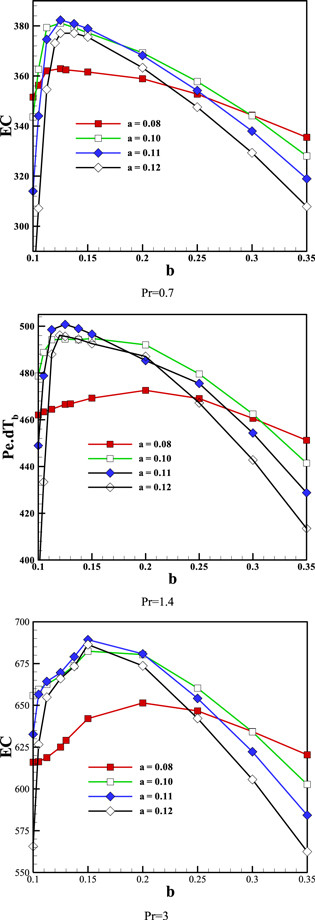
Figure 13. Effective coefficient variations for Re = 500 at different 'a' and Pr, versus 'b'.
Download figure:
Standard image High-resolution imageFigure 14 shows EC for Re = 700 for different Prandtl number and different sizes of the block versus 'b'. It can be seen that EC has a maximum value at b = 0.2 for a = 0.08 and at b = 0.15 for a greater size of 'a'. Also, increasing the size until a = 0.11 increases the maximum EC, but for greater sizes, the 'EC' decreases. Then for Re = 700, the optimum size and situation are a = 0.11 and b = 0.15 for all Prandtl numbers. In figures 13 and 14 the maximum value of 'EC' increases with Peclet number.

Figure 14. Effective coefficient variations for Re = 700 at different 'a' and Pr, versus 'b'.
Download figure:
Standard image High-resolution imageA comparison between a square block in our previous work [13] and diamond block (present work) has been made in figures 15–17. Figure 15 shows a comparison of the friction factor between diamond and square blocks at Re = 500. It is evident that for great size of block, the friction factor for diamond shape is more than it for square block. It may be in opposite with our sense about drag force in the free stream around the bodies. Because, due to the direct impact of the flow on the body we expect the friction factor to be higher for the square block in comparison with the diamond block. While it is just the opposite. The reason is related to the size of the area of the block image perpendicular to the stream direction (A).

This area for a diamond block is  times bigger than the square block. In a lower size of the block, the effect of direct impact is compensated by the bigger image perpendicular to the stream and it leads to friction factor for square block be equal to friction factor for diamond block approximately. But for greater size, the bigger image perpendicular to the stream has a more effective role and the friction factor for diamond block is larger.
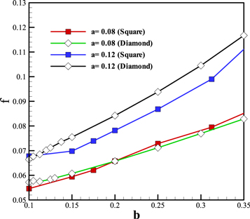
Figure 15. Friction factor comparison between square and diamond blocks for Re = 500 at different 'a' versus 'b'.
Download figure:
Standard image High-resolution image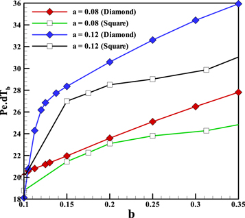
Figure 16. Bulk temperature comparison between square and diamond block for Re = 500 and Pr = 0.7 at different 'a' versus 'b'.
Download figure:
Standard image High-resolution image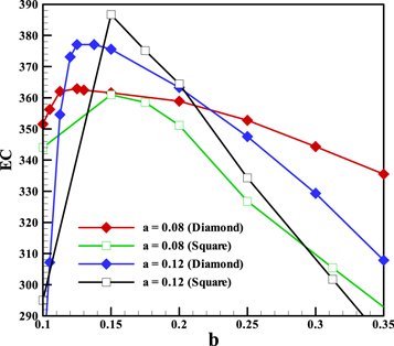
Figure 17. Effective coefficient comparison between square and diamond block for Re = 500 and Pr = 0.7 at different 'a' versus 'b'.
Download figure:
Standard image High-resolution image
In heat transfer behavior for both sizes, the diamond block has a higher heat transfer rate. This behavior is depicted in figure 15 and shows how bigger image perpendicular to the stream is important.
Figure 17 shows the comparison of 'EC' between square and diamond block. It is clear that in general, the diamond block has a higher EC but the maximum EC for a = 0.12 occurs for a square shape. It is due to the complicated behavior of recirculation zones of fluid flow and direct impact to the square block and their effects on the heat transfer behavior of the blocks. Then to make a decision using a diamond or square block it suggested using the square in b = 0.15 and a = 0.12.
5. Conclusions
The main aim of this paper was finding the best size and location of the diamond isotherm blocks such as blocks containing the PCM's. Different parameters such as (0.1 < b < 0.35 and 0.08 < a < 0.12), different Reynolds numbers (500 and 700) and different Prandtl numbers (0.7, 1.4, 3) have been investigated. The well-known SIMPLE method has been employed to solve the governing equations. Results show that, by increase 'a' and 'b', both of the main parameters, the friction factor and the heat transfer rate are increased. Also, there is an optimum location and size for temperature drop to friction factor ratio. For Re = 700, the maximum value of the 'EC' occurs in a = 0.11 and b = 0.15. In comparison with square blocks, the diamond blocks have a larger friction factor and heat transfer rate. The reason for having a larger friction factor for the diamond block is having larger image perpendicular to the flow in comparison with the square block. But in the optimum state, the square blocks have larger EC. The results could be used in air conditioning designing with PCM blocks (containing mixture of water and ice) or in a microchannel with laminar flow to increase heat transfer with attention to the friction coefficient.