
Abstract
Nanobeams are extensively used in the arena of modern science and technology. The dynamic model of nanobeam with steps and cracks is formed by the combination of classical beam theory and nonlocal theory of elasticity. Homotopy perturbation method is employed to solve the governing equations for two steps nanobeam. The results of this approximation method are compared with the results of exact solution technique. Our vital concern is to analyse the effect of rotatory inertia on the dynamic behaviour of nanobeam. The effect of crack severity, crack and step position, step height ratio, axial load on the vibration of nanobeam are also studied. The results show that the effect of rotatory inertia is very significant in the nanobeam and its influence increases with the increase of mode of frequency.
Export citation and abstract BibTeX RIS
1. Introduction
In recent years, researchers are attracted by nano elements due to their unavoidable role and extensive use in modern technology. Nano elements are widely implemented in numerous micro/nanoelectromechanical systems where nanobeam like structures are identified as basic ingredients of these small systems [1, 2]. Researchers confronted the challenge of adequate theory for analysing nano elements. Classical continuum theory is not effective for the nano elements because of their small size. At nanoscale, surface volume ratio is very high and atomic attraction changes the strength of the elements [3, 4]. After that, Eringen proposed nonlocal theory of elasticity. This theory is used widely to solve the various problems of nanostructure.
Understanding the dynamic behaviour of nanobeam is very essential for effective design of electromechanical system. Unfortunately, effect of rotatory inertia is ignored in most of the research. In nanostructure, effect of rotatory inertia is very significant. Presence of steps and cracks is also very obvious in nanostructure. Step is essential for optimal design to investigate vibration of structure under stepped cross-section or variable cross-section [5, 6]. Stepped beams are extensively used in many industrial applications. Stepped beam is more economical because it increases cross-section along the critical segment instead of all throughout the span. Stepped beam under vibration load face complex excitation that may be the cause of failure. It is very essential to develop a reliable model to study stepped beam under vibration [7–11]. Structural defects such as crack are very common in nano elements. Crack in structure reduces the strength of the elements and lead to overall failure. Therefore, it is very crucial to develop analytical models to comprehend the dynamic behaviour of the element with crack [12]. The major effect of these crack in the elements is to reduce vibrational parameters, resonant amplitude, natural frequency, damping factor and above all the stiffness of the elements [13–15]. Crack is modelled by a rotational spring of certain stiffness which is related to the crack depth and loading conditions [16–18]. The influence of rotatory inertia on dynamic instability of stepped beam is very important. It is observed that rotatory inertia can be neglected in the case of slender beam of constant thickness. It is demonstrated by many researchers that the effect of rotatory inertia can be significant when the cross-sectional dimensions of a beam are large in comparison to its length, it is also crucial in the higher mode of frequency [19–22].
In open literature, there are very few papers that expose the effect of rotatory inertia on vibration of cracked and stepped nanobeam. However, many researchers showed their interest in similar types of topics. Loghmani et al [23] and Bahrami [24] investigated free vibration of multi cracked nanobeams using wave propagation method. They showed the effectiveness of wave propagation method for dynamic analysis of cracked nanobeam. Similarly, lattice stiffness method [25] and finite element method [26] were also employed to solve free vibration of cracked nanobeam problem. Roostai and Haghpanahi [27] described analytical technique based on exact solution to study free vibration of nanobeams with multiple cracks. They analysed the effects of nonlocality, crack location and crack parameter on the natural frequencies of the cracked nanobeam. Similarly, homotopy perturbation method is very popular technique among researchers to solve various problems. However, there is no evidence that researcher used this technique to solve multi-steps nanobeam. Some researchers solved different problems of solid mechanics using homotopy perturbation method. Ghadiri and Safi [28] analysed nonlinear vibration of functionally graded nanobeam using perturbation method. Mutman [29] analysed free vibration of an Euler beam of variable width on the winkler foundation using perturbation method.
In the present paper, the dynamic behaviours of cracked and stepped nanobeam are investigated using the approximation and exact solution techniques. Our main concern is to analyse the effect of rotatory inertia on the natural frequency of nanobeam. The homotopy perturbation technique is employed to solve the governing differential equations considering boundary conditions for end supports and intermediate conditions for steps and cracks. The results of this technique are compared with the results of exact solution technique. The effect of crack severity, crack position, step height ratio, nonlocal parameter, axial tension on dynamic behaviours of nanobeam are analysed in detail.
2. Settings of problem
A schematic shape of a stepped and cracked nanobeam is illustrated in figure 1. It is considered that the origin of the coordinate system is placed at the left corner point of the nanobeam. The axis of the beam coincides with the  axis and height of the beam along the
  axis. The nanobeam with length
  and rectangular cross-section of width
  is considered. The density of the beam
  is uniform throughout the beam and the axial load
  is also applied uniformly over the nanobeam. Crack and step are placed at the same location at
  of the beam. So, there is a discontinuity at that location with different heights

Figure 1. Geometry of the problem.
Download figure:
Standard image High-resolution imageThe crack is treated as stable crack whose depth is  and
and  is the ratio of crack depth and beam height. This crack is also considered by an equivalent linear spring connecting the two segments of the nanobeam.
3. Mathematical Model
According to the nonlocal theory of elasticity, constitutive equations incorporate the effects of atomic forces and small scale as material properties. The theory states that stress tensor at a reference point depends on the strain field at all points of the continuum [30]. So the relationship of stress and strain for a homogeneous elastic solid can be expressed as below:

where  and
and  are the nonlocal and local stress tensors, respectively.
  is the nonlocal modulus that indicates the effect of the strain at the point
  on the stress at the point
  where
where  depends on the internal and external length characteristic (e.g. length of two carbon molecule bonds and length of nanobeam). The combine form of nonlocal theory [30] and Euler–Bernoulli theory can be described as:

where  denotes the internal characteristic length, and
  is a constant depending on the material characteristics. The value of
  depends on lattice parameter, granular size and atomic bonds, and the material constant.
  is called the small scale parameter.
  indicates the normal strain which can be presented as (see [31]):

in which  and
and  are the coordinates along the length and depth of beam respectively.
  is the lateral displacement. According to the definition of the bending moment:

the bending moment M can be defined as:

where  presents the second moment of area and
  is the modulus of elasticity. Equilibrium equation for the free lateral vibrating Euler–Bernoulli beam can be written as (see [31]):

in which  denotes the axial force that is considered constant throughout the beam.
  represents the rotatory inertia as
 is the density of the material and
  is the time.
Combining the equations (5) and (6) it can be written as:

Differentiating (7) twice with respect to  gives as:

It can be written from equations (6) and (8) as below:

Considering  equation (9) can be transformed into ordinary differential equation as:

where  is the dimensional frequency for free vibrations. The dimensionless variables are introduced as below:

Equation (10) can be simplified as follow:

Considering the two segments of the beam, equation (11) can be written as follow:

and

where 
 and
and 
To solve the above equations (12), (13) the required boundary conditions are as follow:
For simply supported ends

For clamped supported ends

For clamped simply supported ends

For clamped free supported ends

4. Crack formulation
The basic formulation for elastic crack was established in 1921 by Griffith. According to Griffith, crack propagation will occur if the energy upon crack growth is sufficient to provide all the energy that is required for crack growth [32]. The condition for crack growth is

where  is the elastic energy and
  is the energy required for crack growth. Griffith calculated
  as:
as:

Usually  is replaced by
where  is also called the crack driving force. It can be presented [33] as:

where

and  is the Poisson ratio.
  can be defined by trigonometric function or algebraic function [34] as below:

and

where

Intermediate conditions for steps and cracks are as follow:

5. Solution
The homotopy perturbation method is very effective technique. It is used successfully in various linear and nonlinear problems. He [35] proposed this method in 1998. The general form of HPM can be written as:

and

where  is a linear operator, and
  is a nonlinear operator,
  is a boundary operator. The solution of this equation can be presented as a power series of
  as follow:

In this technique  so the solution can be written as:

Using the basic principle of homotopy peturbation method (HPM), we can write the governing equation as follow:
for 

for 

we consider the following approximations


to solve the governing differential equation. Using the boundary and intermidiate conditions, eigth equations are formed with eight unknowns . These equations can be presented in a matrix form as below:

The determinated of the coefficient matrix can be presented as a function of  for nontrivial solution. The real value of
  represent the natural frequency of nanobeam. Also this problem is solved using the exact solution technique [36]. The results of these both techniques are also compared.
6. Results and discussion
The progress and development of nanotechnology are very rapid and significant. However, it is a matter of challenge to develop or create a reliable measurement technique which will provide efficient accuracy. In this section, the dynamic behaviour of stepped and cracked nanobeam is solved by the HPM and exact solution method. These techniques are very effective and reliable among researchers.
A nanobeam with the following parameters is considered in this analysis such as 
 Different types of supported nanobeams with single step and crack are considered in this study. At first, the accuracy of the analysis is measured by comparing the results of HPM with the results of exact solution technique. Then, the effect of nonlocal parameter, step and crack location, crack depth, axial load on natural frequency are presented for different boundary conditions and different values of nonlocal parameter. The results of the calculation are depicted in tables 1, 2 and figures 2–13. The results of exact solution are presented by the solid line and the results of HPM are presented by the dashed line in these graphs. Lines with large dots indicate the higher value of the nonlocal parameter. All the effects are presented in figures 2–13 for simply supported and fully clamped nanobeam separately.
Table 1. Natural frequency of nanobeam under different support systems.
| SS | CS | CC | CF | ||||||
|---|---|---|---|---|---|---|---|---|---|
| ε | Mode | HPM | Exact | HPM | Exact | HPM | Exact | HPM | Exact |
| 0 | 1 | 9.981 445 | 9.869 384 | 15.514 45 | 15.417 23 | 22.514 06 | 22.373 53 | 3.538 183 | 3.515 917 |
| 0 | 2 | 39.808 59 | 39.477 05 | 50.220 31 | 49.965 33 | 61.953 12 | 61.671 38 | 22.170 31 | 22.035 93 |
| 0 | 3 | 90.643 75 | 88.825 19 | 107.1218 | 104.2412 | 125.6960 | 120.9042 | 62.184 37 | 61.696 87 |
| 0.5 | 1 | 5.406 738 | 5.300 292 | 7.942 382 | 7.784 423 | 11.210 69 | 10.991 21 | 2.380 419 | 2.365 209 |
| 0.5 | 2 | 12.213 86 | 11.974 85 | 14.983 98 | 14.687 01 | 24.809 32 | 24.333 98 | 7.945 800 | 7.796 533 |
| 0.5 | 3 | 18.803 71 | 18.437 98 | 21.683 98 | 21.256 10 | 31.078 02 | 30.486 32 | 15.095 70 | 14.837 40 |
| 1 | 1 | 3.053 540 | 2.993 627 | 4.406 640 | 4.318 237 | 6.177 539 | 6.056 152 | 1.440 795 | 1.442 065 |
| 1 | 2 | 6.328 515 | 6.205 078 | 7.774 560 | 7.621 826 | 9.072 119 | 8.895 019 | 4.500 732 | 4.390 136 |
| 1 | 3 | 9.557 128 | 9.372 656 | 11.047 85 | 14.008 91 | 12.697 65 | 12.452 44 | 7.843 554 | 7.717 333 |
| 1.5 | 1 | 2.089 721 | 2.048 706 | 3.002 294 | 2.942 138 | 4.201 953 | 4.119 921 | 1.003 540 | 1.006 652 |
| 1.5 | 2 | 4.248 291 | 4.165 283 | 5.221 777 | 5.118 652 | 6.082 255 | 5.963 769 | 3.115 429 | 3.033 447 |
| 1.5 | 3 | 6.391 113 | 6.267 089 | 7.393 457 | 7.247 558 | 8.507 031 | 8.342 675 | 5.274 511 | 5.191 894 |
| 2 | 1 | 1.582 336 | 1.551 269 | 2.269 555 | 2.223 754 | 3.174 023 | 3.112 304 | 0.764 892 | 0.767 919 |
| 2 | 2 | 3.193 969 | 3.131 542 | 3.927 001 | 3.849 365 | 4.570 361 | 4.481 640 | 2.372 412 | 2.308 471 |
| 2 | 3 | 4.798 486 | 4.705 859 | 5.551 953 | 5.442 871 | 6.391 015 | 6.268 945 | 3.968 759 | 3.907 958 |
Table 2. Effect of rotatory inertia on natural frequency of nanobeam under different support systems.
| SS | CS | CC | CF | ||||||
|---|---|---|---|---|---|---|---|---|---|
| L/h | Mode | HPM | Exact | HPM | Exact | HPM | Exact | HPM | Exact |
| 100 | 1 | 9.607 031 | 9.411 523 | 14.887 69 | 14.584 96 | 21.502 97 | 21.068 94 | 3.436 523 | 3.503 422 |
| 100 | 2 | 33.818 35 | 33.267 57 | 42.245 89 | 41.488 28 | 51.342 38 | 50.434 17 | 19.111 91 | 19.435 48 |
| 100 | 3 | 65.355 46 | 63.535 64 | 74.714 84 | 73.152 34 | 84.911 13 | 83.193 16 | 46.138 28 | 46.937 85 |
| 20 | 1 | 9.511 230 | 9.321 679 | 14.553 71 | 14.270 50 | 20.553 22 | 20.171 04 | 3.433 25 | 3.500 048 |
| 20 | 2 | 30.443 35 | 30.033 39 | 36.185 54 | 35.705 07 | 41.464 64 | 40.974 80 | 18.515 03 | 18.816 60 |
| 20 | 3 | 47.871 09 | 47.135 93 | 51.246 09 | 50.730 46 | 54.232 22 | 53.770 70 | 39.249 41 | 39.754 49 |
| 10 | 1 | 9.228 90 | 9.055 175 | 13.639 64 | 13.403 32 | 18.234 08 | 17.965 72 | 3.422 070 | 3.488 085 |
| 10 | 2 | 24.117 38 | 23.909 66 | 26.736 32 | 26.535 15 | 28.702 24 | 28.534 96 | 16.917 48 | 17.151 95 |
| 10 | 3 | 30.591 79 | 30.400 39 | 31.447 26 | 31.324 21 | 32.124 60 | 32.025 39 | 28.233 96 | 28.427 73 |
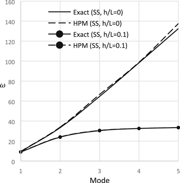
Figure 2. Natural frequency versus mode of frequency (S-S).
Download figure:
Standard image High-resolution image
Figure 3. Natural frequency versus mode of frequency (C-C).
Download figure:
Standard image High-resolution image
Figure 4. Natural frequency versus step height ratio (S-S).
Download figure:
Standard image High-resolution image
Figure 5. Natural frequency versus step height ratio (C-C).
Download figure:
Standard image High-resolution image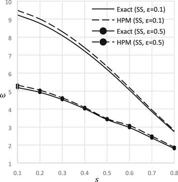
Figure 6. Natural frequency versus crack depth ratio (S-S).
Download figure:
Standard image High-resolution image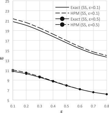
Figure 7. Natural frequency versus crack depth ratio (C-C).
Download figure:
Standard image High-resolution image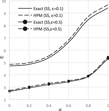
Figure 8. Natural frequency versus step position (S-S).
Download figure:
Standard image High-resolution image
Figure 9. Natural frequency versus step position (C-C).
Download figure:
Standard image High-resolution image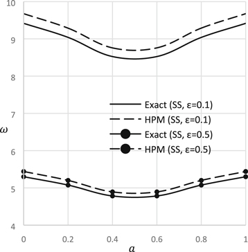
Figure 10. Natural frequency versus crack position (S-S).
Download figure:
Standard image High-resolution image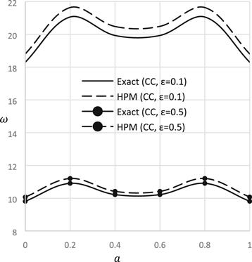
Figure 11. Natural frequency versus crack position (C-C).
Download figure:
Standard image High-resolution image
Figure 12. Natural frequency versus axial load (S-S).
Download figure:
Standard image High-resolution image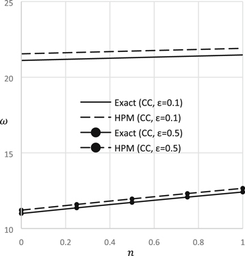
Figure 13. Natural frequency versus axial load (C-C).
Download figure:
Standard image High-resolution image
Table 1 depicts the natural frequency under different support systems. Different modes of frequency and different values of nonlocal parameter are also considered. It is very clear from this table that the natural frequency decreases very rapidly with the increase of nonlocal parameter.
Table 2 illustrates the effect of rotatory inertia on natural frequency of nanobeam under different support systems. It is very clearly described that natural frequency decreases with the decrease of length to height ratio. The effect of rotatory inertia can be ignored in a slender beam.
Figures 2, 3 describe the effect of rotatory inertia on natural frequency for different modes of frequency. Without considering the rotatory inertia, natural frequency increases very sharply with increase of frequency mode. On the other hand, considering small value of height to length ratio, nature frequency reduces drastically with the increase of frequency mode. The effect of rotatory inertia is very significant in higher mode of frequency.
Figures 4, 5 illustrate the natural frequency versus step location for different support conditions and different value of nonlocal parameter. In these graphs, step is considered at the midpoint of the beam. When  it indicates step beam, one side of the beam is thinner than the other so the frequency shows lower value. On the other hand, when
  it indicates the solid beam without step so the frequency shows higher value. It is very obvious that natural frequency increases with the increase of step height ratio.
Figures 6, 7 expose the natural vibration versus crack height ratio for different support conditions. In these figures, crack is considered at the midpoint of the beam. It is very obvious that natural frequency decreases with the increase of crack height ratio because increase of crack height ratio decreases the stiffness of the beam.
Figures 8, 9 reveal the natural frequency versus step position for different support conditions. The step height ratio  is considered for these beams. In these figures,
  indicates thinner beam without step. On the other hand,
  indicates thicker beam without step. It is very evident that thinner beam shows lower frequency and thicker beam shows higher frequency. Change of step position increases beam cross-sectional area as well as natural frequency.
Figures 10, 11 describe the natural frequency versus crack depth ratio for different support conditions and different values of nonlocal parameter. Crack depth  is considered for these beams. In simply supported beam, crack position at mid span shows lower frequency. On the other hand, in fully clamped beam, crack position at the support shows lower frequency.
Figures 12, 13 demonstrate the natural frequency versus axial load for different support conditions and different values of nonlocal parameter. The natural vibration increases with the increase of axial load because this axial load acts as a compressive load on the beam that increases stiffness and natural frequency. The effect of axial load is more significant at the higher value of nonlocal parameter.
7. Conclusion
In this study, a mathematical model which is based on Eringen's nonlocal theory of elasticity and Euler–Bernoulli beam theory is presented for free vibration analysis of nanobeam with step and crack as a defect. Homotopy perturbation method and exact solution technique are employed to solve this multi-steps nanobeam. The results of these both techniques show very good correlations. The results are presented for different types of support conditions and different values of nonlocal parameter. The effects of geometric parameters such as step ratio, step location, crack depth, rotatory inertia as well as physical parameters such as nonlocal parameter, axial load are discussed in detail. The results of this investigation showed that the effect of cracks and steps on the natural frequency is very significant. The effect of rotatory inertia is also very significant in clamped supported nanobeam and higher mode of frequency. This analysis can be used as benchmarks for other works and also it can be used to design nanoelectromechanical system.