


1. Introduction
Hot-water ice drill systems are actively used in polar science for the observation of ocean cavities under ice shelves; retrieval of sub-ice seabed samples; study of internal ice structures, video imaging and temperature logging; measurements of deformation within ice; determination of basal sliding velocity; clean access to subglacial lakes; and many other scientific objectives (Tsutaki and Sugiyama, Reference Tsutaki and Sugiyama2009; Makinson and Anker, Reference Makinson and Anker2014; Rack and others, Reference Rack2014). Hot-water drill systems appear simple. During the initial stage of drilling operations, a certain volume of water should be prepared to begin drilling. Water is pumped at high pressure through a drill hose to a nozzle that jets hot water to melt ice. The hose and nozzle are lowered slowly to form a straight hole because gravity is used as the steering mechanism. The water from the nozzle uses the melted hole as the return conduit. An additional pump (either submersible or at the surface) is, in most cases, installed to pump water to a surface water tank. This water is then reused by the hot-water drill.
Hot-water drilling is a rapid method for drilling boreholes in glaciers. The rate of penetration (ROP) of the fastest system, designed by the Geological Survey of Greenland for bedrock topography studies near Jakobshavn, West Greenland, reached 300 m h−1 in firn and 125–200 m h−1 in clear ice (Olesen, Reference Olesen1989). Typically, hot-water drilling systems are used to create access holes. However, hot-water ice-coring drills can also be used to recover ice core samples from desirable depths by drilling with annular nozzles. In conjunction with a hot-water drill, they can provide a series of ice cores for site-selection studies and for the determination of ice properties when complete cores are not essential. Because borehole drilling and ice coring are performed with only hot water, contamination with the other fluids used for mechanical drilling cannot occur and ice-cutting chips are not produced, thereby simplifying the core-handling procedures.
The first hot-water coring tools were investigated simultaneously using the hot-water drill of the Thayer School of Engineering at Dartmouth, USA, and several coring technologies were tested during 1978–1979 season in Antarctica, where varying degrees of success were achieved (Browning and others, Reference Browning, Bigl and Sommerville1979). In the early 1990s, Caltech designed a hot-water ice-coring drill and used it in combination with a full-scale hot-water drilling system (Engelhardt and others, Reference Engelhardt, Kamb and Bolsey2000). The drill comprised a cutting drill head (Fig. 1), four thermally insulated 6-mm stainless-steel tubes along the outside of a Lexan core barrel and a back-drilling head. The cutting drill head had 40 jets, each measuring 1 mm in diameter, on an annulus of diameter 108 mm. The axes of the jets were tilted outward at a 12° angle from the vertical axis of the drill. In 1993/94 season, the hot-water ice-coring drill was used successfully to retrieve 18 ice cores of up to 2 m long and ~70 mm in diameter from the depths of 300 to 950 m in the heavily crevassed chaotic shear zone between the Whillans Ice Stream and the Unicorn, West Antarctica.
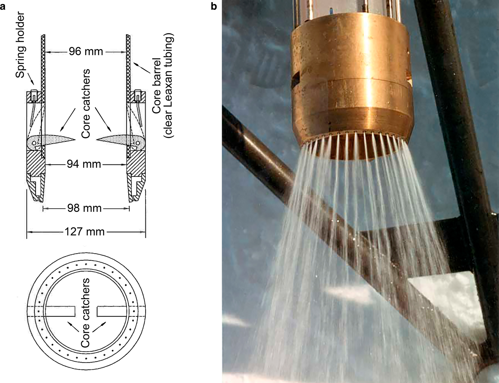
Fig. 1. Caltech hot-water cutting drill head: (a) schematic drawing (Engelhardt and others, Reference Engelhardt, Kamb and Bolsey2000); (b) during testing (Credit: K. Makinson).
Over the last two decades, a significant number of cores have been drilled using different versions of the Caltech ice-coring drill in Iceland (Gaidos and others, Reference Gaidos2004) and at several Antarctic sites, including the Siple Dome (Gow and Engelhardt, Reference Gow and Engelhardt2000), Ronne Ice Shelf (Nicholls and others, Reference Nicholls, Corr, Makinson and Pudsey2012), Rutford Ice Stream (Smith, Reference Smith2005), Amery Ice Shelf (Craven and others, Reference Craven, Elcheikh, Brand and Jones2002, Reference Craven, Allison, Fricker and Warner2009; Treverrow and others, Reference Treverrow, Warner and Budd2010) and Ross Ice Shelf (Rack, Reference Rack2016). Although the coring drill head and core barrel differ among these modified versions, the drills' design has primarily adhered to the prototype design.
The major drawback of hot-water ice coring using Caltech's drill is the variations in quality of the recovered cores. For example, the nominal core diameter of the Australian version of the Caltech corer was 100 mm, but the diameter of the recovered cores at the Amery Ice Shelf was reduced to ~60 mm in some sections of the cores because a mismatch occurred between the vertical velocity of the coring attachment and the water temperature of the drill system (Treverrow and others, Reference Treverrow, Warner and Budd2010). At that time, cores varied from well-formed cylindrical samples that were over 1 m long to samples that were 0.2 m in length with tapered ends. Occasionally, the diameters of the cores were too small to be caught by core catcher and no cores were retrieved (Vogel and others, Reference Vogel2005; Nicholls and others, Reference Nicholls, Corr, Makinson and Pudsey2012).
The most critical part of the hot-water ice coring drill is the annular drill head through which water jets to the bottom of the hole and forms the core. To overcome the limitations of hot-water ice coring, the annular drill head must be optimized. The effect of the drill head structure (diameter of water nozzles; their number and angle from the vertical axis of the drill) on the quality of ice cores (length and maximal diameter) and ROP remains unclear. Here we describe the results of the experimental investigations of a hot-water ice coring drill with nine drill heads according to the orthogonal test design method. Consequently, the optimal design of the drill heads that yield the highest quality ice cores is determined.
2. Orthogonal test design
The orthogonal test design was used to investigate the effects of various nozzle structures (angle, number and diameter) on the coring performance. It is a type of design method for studying multivariate and multilevel factors, in which tests are conducted by selecting a suitable number of representative test cases that exhibit evenly dispersed and neat comparable characteristics (Park, Reference Park2007).
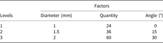
The test design is based on the orthogonal table. Factors in the table are parameters affecting the performance, while levels are the typical values of the factors. In this study, the nozzle diameter, number and angle were set as the factors and their corresponding levels are as shown in Table 1. The levels were selected by analyzing the design of different versions of the Caltech hot-water ice-coring drill.
Table 1. Factors and levels based on orthogonal design
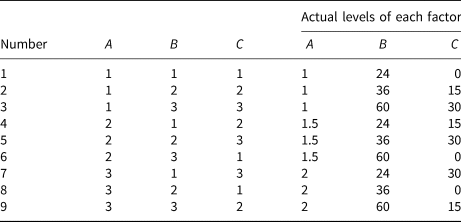
Consequently, the normalized orthogonal table L 9 (34) with four factors and three levels was designed. The factors of nozzle diameter, number and angle are marked with the capital letters A, B and C, respectively (Table 2).
Table 2. Orthogonal test design table L 9 (34)
A prototype of the hot-water ice-coring drill (Fig. 2) with replaceable drill heads and nine drill heads of the same size but with unique nozzle structures was designed and processed (Fig. 3). The length of the drill was 1.8 m and its weight was 24 kg. The inner diameter/outer diameter ratio of the ice-core drill head was 96/140 mm. The drill heads were connected to the drill by screw joint, and two O-rings were used to seal the connection (Fig. 4). Hot water was supplied through six 10-mm diameter tubes fixed to the outer surface of the core barrel.
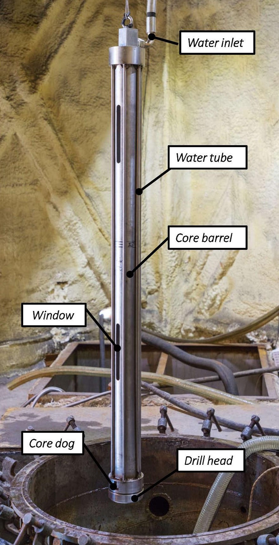
Fig. 2. Hot-water ice-coring drill during laboratory tests.
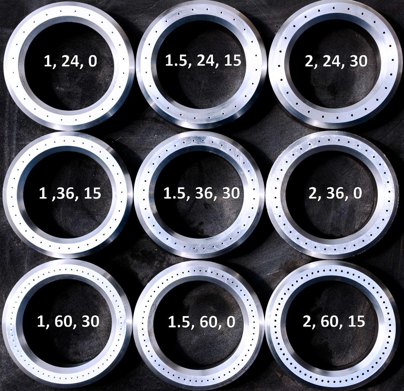
Fig. 3. Interchangeable drill heads; the numbers inside indicate diameter of the nozzles, the number of nozzles and angle from the vertical axis of the drill.
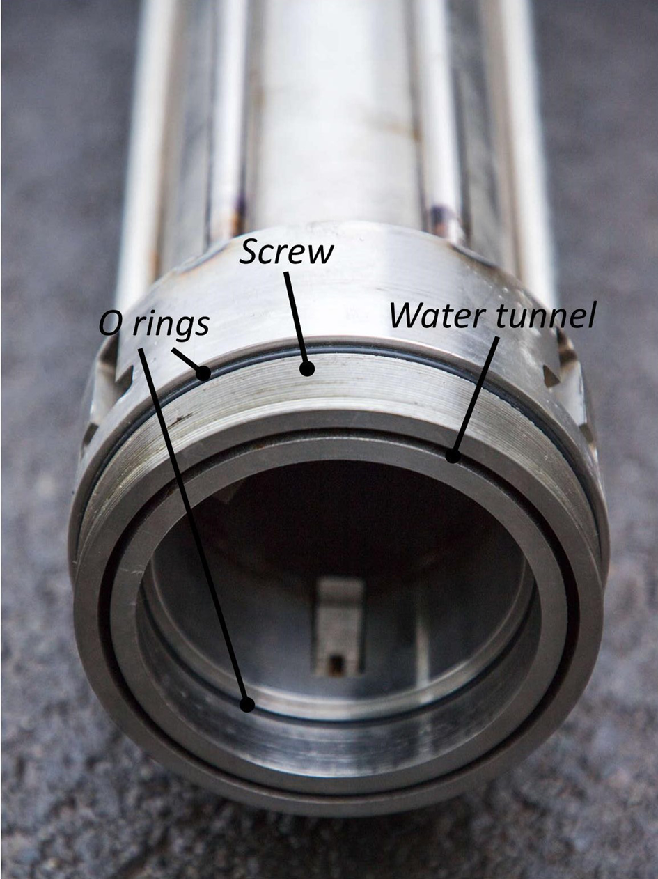
Fig. 4. Screw connection at the lower part of the drill.
3. Testing procedure
Tests were performed in an ice drill testing facility that allows the testing of numerous mechanical and thermal ice drills throughout the year (Wang and others, Reference Wang2018). The facility comprises an ice well (12.5 m deep and 1 m diameter) with the minimum ice temperature of −30°C. The hot-water ice-coring drill was suspended over the ice well using the wire rope of the rotary drilling platform; the wire rope was passed through the pulley and connected to the winch, with a variable speed drive to control the lowering rate of the drill.
Water in the drilling fluid pit was heated by a heater and subsequently pumped through the hose by a high-pressure pump into the drill, on which the annular drill head sprayed water out and melted ice for penetration. When the drilling was completed, the submersible pump in the ice collected water in the water tank; subsequently, the water was pumped into the drilling fluid pit and heated again for the next drilling (Fig. 5).
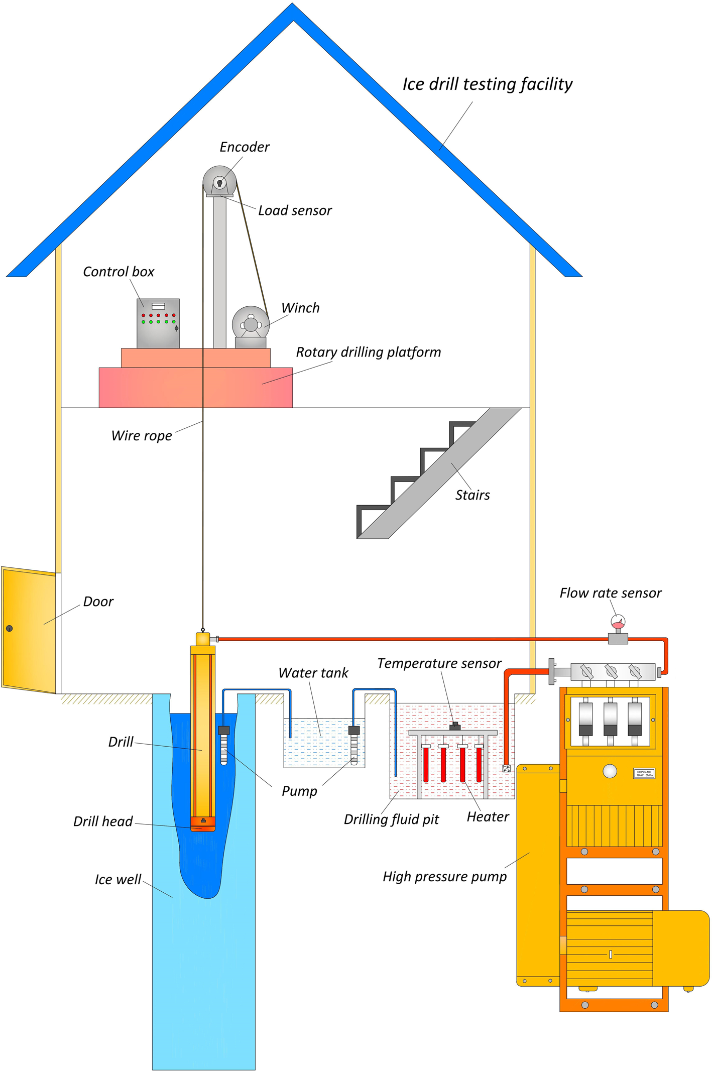
Fig. 5. Schematic of hot-water ice-coring drilling testing.
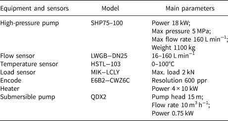
Several types of sensors were installed, including a flow meter at the outlet of the high-pressure pump, a load sensor underneath the pulley and a temperature sensor in the drilling fluid pit (Table 3). The load sensor was used to monitor if the drill had touched the bottom and the temperature sensor was used to measure the water temperature of the heated water. The downward speed of the drill was adjusted by controlling the winch speed to maintain a balanced state. Drilling penetration was measured by the encoder installed on one side of the pulley.
Table 3. Main parameters of the equipment and sensors used
The drill heads were numbered 1 to 9, as shown in Table 2. The flow rate of intermediate hot-water ice drilling systems, designed for drilling to depths up to 1000–1500 m, are typically from 45–90 L min−1 (Talalay, Reference Talalay2020); thus, three water flow rates were selected, i.e., 40, 70 and 100 L min−1. Holes were drilled to the depth of 1 m at a constant water temperature of 50 ± 3°C (Fig. 6). This temperature was selected from the experimental observations of Liu and others (Reference Liu2019).
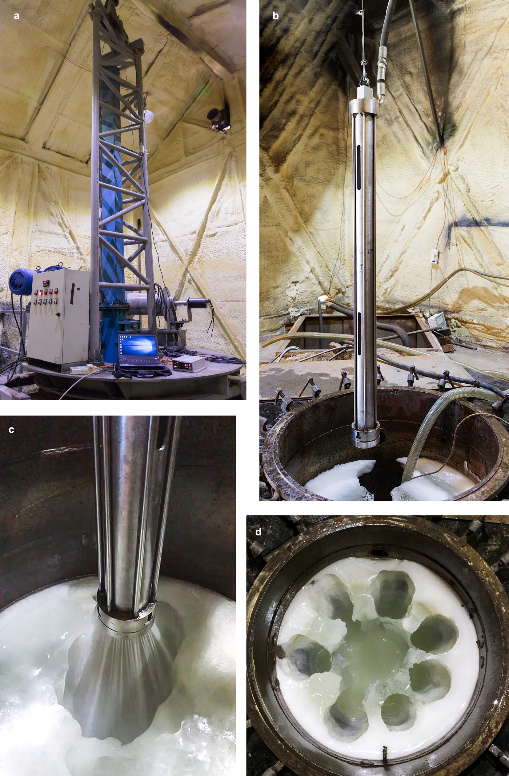
Fig. 6. Overview of the hot-water ice-coring drilling tests: (a) measuring and control system; (b) drill suspended over the ice well; (c) drilling; and (d) ice well after tests.
After each test, we removed ice cores from the core barrel and measured the maximum/minimal diameter and length of the core using a caliper and a ruler. We discovered that the ice cores were primarily intact cylinders and that the diameters of the ice cores were almost uniform, with small fluctuations between the maximum and minimum diameters (typically 8–10%; up to 30% in certain cases) (Fig. 7). Therefore, the maximum diameter was selected to evaluate the quality of the ice cores. The average penetration rate was calculated using the drilling depth and drilling time.
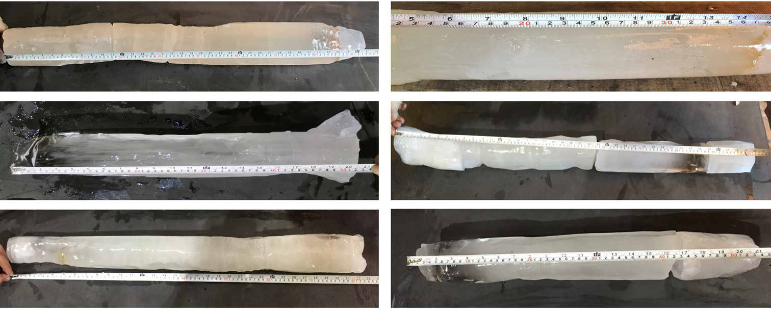
Fig. 7. Ice cores retrieved by the hot-water ice-coring drill.
4. Results and Discussion
A total of 27 testing runs were performed according to the orthogonal test design method (Supplementary material, Table S1). To evaluate the quality of the ice cores, we used a coring ratio – the ratio between the maximum diameter of the ice core and the inner diameter of the core barrel (96 mm) (Fig. 8). The coring ratios are primarily between 0.593 and 0.885 except for head #8, which exhibits ratios exceeding 0.521; this indicates that most drill heads used in the tests can retrieve ice cores of relatively good quality.
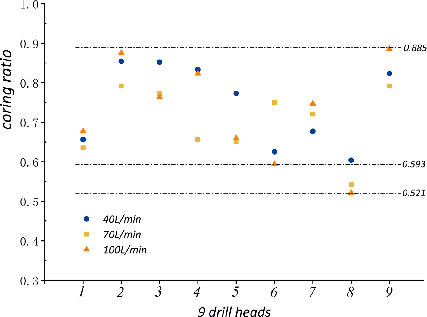
Fig. 8. Coring ratio distributions of nine drill heads with different flow rates.
The orthogonal test design method provides several types of analysis methods including intuitive, range and trend analysis, which facilitate in understanding the most significant factor of the nozzle structure.
4.1. Intuitive analysis of testing results
When the flow rate is 40 L min−1, drill heads #2, 3 and 4 can retrieve ice cores of maximum diameter exceeding 80 mm. When the flow rate is 70 L min−1, drill heads #2 and #9 can obtain ice cores of maximum diameter 76 mm and length exceeding 0.9 m. When the flow rate is 100 L min−1, drill heads #2 and #9 can obtain ice cores of diameter exceeding 84 mm and a length exceeding 0.93 m. Considering the three tested flow rates, drill head #2 can be considered as the optimal option and the best parameter combination is A 1B 2C 2. This means that the drill with a nozzle diameter, number and angle of 1 mm, 36 and 15°, respectively, can produce cores of the highest quality.
4.2. Range analysis of testing results
The range analysis of testing results with flow rates of 40, 70 and 100 L min−1 are presented in the Supplementary material (Tables S2, S3 and S4, respectively). To analyze the effect of different factors, we used the following parameters: Ki, the sum of the 3 testing levels for a single factor with level i; $\bar{K} i$ , the average value of Ki; R, the difference in value between the maximum and minimum values of $\bar{K} i$
 (a larger R value indicates more significant effects).
In most cases, the factor C (nozzle angle) is always the first in the ranking of R, indicating the maximum effect on the coring performance. The values of R in factors A (nozzle diameter) and B (number of nozzles) are smaller and close to each other, however, in most cases, the ranking is RB > RA. Thus, the number of nozzles is the second most important factor for ice coring. However, the nozzle diameter has a greater effect on the maximum diameter of the ice cores.
4.3. Trend analysis of testing results
Using the value of $\bar{K} i$ , trend analysis was performed to analyze the internal connection between the selected levels and the results and to investigate possible better levels that were not selected in the tests. The method uses a tendency chart, in which the abscissa is the level of factors and the ordinate is the corresponding testing results. All values of $\bar{K} i$
 are plotted on the charts (Fig. 9). The trend tendencies of all curves are highly similar and can consequentially verify the authenticity of the tendency.

Fig. 9. Effects of various factors and levels with different flow rates on coring performance.
When the nozzle diameter was increased from 1 to 2 mm, the length of the retrieved ice cores increased as well, while the maximum diameter of the ice cores and ROP decreased. When the number of nozzles was increased from 24 to 60, the diameter and length of the ice cores increased to a certain extent except for the ROP, which decreased slightly. Thus, to retrieve high-quality cores, the head with a large number of nozzles must be used. The diameter and length of the ice cores first increased rapidly with the nozzle angle and then decreased to a value that was still higher than that obtained with a 0° nozzle angle. The best-quality cores were obtained using heads that had a nozzle angle of 15°.
5. Conclusions
In this study, various drill heads of the hot-water ice-coring drill with different nozzle diameters, numbers and angles were designed and tested based on the orthogonal test design method. The following conclusions can be derived from the study:
(1) Intuitive analysis of testing results indicated that the following parameters of the nozzle yielded good-quality ice cores: nozzle diameter of 1 mm, 36 nozzles and nozzle angle of 15°.
(2) Nozzle angle was the most significant factor affecting the coring performance and it must be ~15° to obtain high-quality ice cores.
(3) The number of nozzles was the second most important factor and a large number yielded better quality ice cores.
(4) The number of nozzles had a greater effect on the length of the ice core and the nozzle diameter on the maximum diameter of the ice core.
(5) The following nozzle parameters yielded the maximum diameter of the ice core: nozzle diameter of 1 mm, 60 nozzles and nozzle angle of 15°, whereas those resulting in the maximum length of the ice core were nozzle diameter of 2 mm, 60 nozzles and nozzle angle of 15°.
The experimental results could not provide a universal model for every nozzle diameter/number/angle; however, it is still a prominent reference for the prediction of ice core quality drilled in glaciers and ice sheets using hot-water drills.
Supplementary material
The supplementary material for this article can be found at https://doi.org/10.1017/aog.2020.63.
Acknowledgement
This research was supported by the program for the Jilin University Science and Technology Innovative Research Team (Project No. 2017TD-24). We are grateful to the members of our research team for their help in design and testing. We thank Scientific Editor J. Schwander (University of Bern, Switzerland), A. Pyne (Victoria University of Wellington, New Zealand) and anonymous reviewer for fruitful suggestions, useful comments and editing.


 Open access