Sequential Combustion in Steam Methane Reformers for Hydrogen and Power Production With CCUS in Decarbonized Industrial Clusters
 Laura Herraiz
 Mathieu Lucquiaud
 Hannah Chalmers
 Jon Gibbins
- 1School of Engineering, The University of Edinburgh, Edinburgh, United Kingdom
- 2Department of Mechanical Engineering, The University of Sheffield, Sheffield, United Kingdom
In future energy supply systems, hydrogen and electricity may be generated in decarbonized industrial clusters using a common infrastructure for natural gas supply, electricity grid and transport and geological storage of CO2. The novel contribution of this article consists of using sequential combustion in a steam methane reforming (SMR) hydrogen plant to allow for capital and operating cost reduction by using a single post-combustion carbon capture system for both the hydrogen process and the combined cycle gas turbine (CCGT) power plant, plus appropriate integration for this new equipment combination. The concept would be widely applied to any post-combustion CO2 capture process. A newly developed, rigorous, gPROMs model of two hydrogen production technologies, covering a wide range of hydrogen production capacities, thermodynamically integrated with commercially available gas turbine engines quantifies the step change in thermal efficiency and hydrogen production efficiency. It includes a generic post-combustion capture technology – a conventional 30%wt MEA process - to quantify the reduction in size of CO2 absorber columns, the most capital intensive part of solvent-based capture systems. For a conventional SMR located downstream of an H-class gas turbine engine, followed by a three-pressure level HRSG and a capture plant with two absorbers, the integrated system produces ca. 696,400 Nm3/h of H2 with a net power output of 651 MWe at a net thermal efficiency of 38.9%LHV. This corresponds to 34 MWe of additional power, increasing efficiency by 4.9% points, and makes one absorber redundant compared to the equivalent non-integrated system producing the same volume of H2. For a dedicated gas heated reformer (GHR) located downstream of an aeroderivative gas turbine engine, followed by a two-pressure level HRSG and a capture plant with one absorber, the integrated system produces ca. 80,750 Nm3/h of H2 with a net power output of 73 MWe and a net thermal efficiency of 54.7%LHV. This corresponds to 13 MWe of additional power output, increasing efficiency by 13.5% points and also makes one absorber redundant. The article also presents new insights for the design and operation of reformers integrated with gas turbines and with CO2 capture.
Introduction
Electricity and hydrogen are two low-carbon energy vectors expected to play key roles in a zero carbon economy, for example to decarbonize power, buildings (heating and cooling), transport and industry sectors. In future energy supply systems there will be a number of examples of both vectors being generated from natural gas at the same location, where a common infrastructure is available for natural gas supply, electricity grid connection and transport and geological storage of CO2 in carbon capture, utilization and storage (CCUS) industrial clusters (BEIS, 2018).
The possibility of producing hydrogen by a low-carbon route and storing it at scale makes it a potentially valuable complement in the long-term decarbonization of parts of the energy system where electrification is not feasible and/or more expensive. Besides being a fuel or raw material for some energy intensive industries, low-carbon hydrogen can replace natural gas for space heating in buildings, industrial processes and back-up power generation and be used as a fuel in heavy transport. Hydrogen distribution networks are also anticipated, provided that sufficient volumes of hydrogen can be produced at a competitive price (Committee on Climate Change [CCC], 2018).
Natural gas reforming with carbon capture and storage (CCS) is expected to be a cost-effective option for industrial scale production of low-carbon hydrogen and can therefore help lay the foundation for much higher use of hydrogen across the whole economy (Committee on Climate Change [CCC], 2018). Currently steam reforming of natural gas or light hydrocarbons at an appropriate temperature and pressure in the presence of a suitable metal-based catalyst is the leading source of hydrogen used in petrochemical and petroleum refining applications, yet it has high emissions of carbon dioxide, at approximately 7 to 10 kgCO2/kgH2 on average. Modern steam methane reformers (SMRs) are widely used for hydrogen production and have achieved high efficiencies, reducing CO2 emissions down to nearly 10% above the theoretical minimum and further reduction would only be possible with CCS (IEAGHG, 2017b). In addition to the supply of natural gas as feedstock for synthesis gas and hydrogen production in a SMR, the combustion of natural gas and the tail gas from hydrogen production and separation provides the thermal energy for the high temperature heat transfer necessary to drive the endothermic reforming reactions in the catalytic reactor.
The novel contribution of this article consists of a technique for modifying the combustion in an SMR to allow for capital and operating cost reduction by integration to use a single post-combustion carbon capture (PCC) system for both the SMR and a combined cycle gas turbine (CCGT) power plant, plus appropriate integration for this new equipment combination. A review of other types of hydrogen production facilities with CCS that are also currently being considered for imminent deployment is beyond the scope of this study, but the SMR with PCC in its current form appears competitive (e.g., see Element Energy Ltd, 2018) and thus a description of possible improvements through such integration is topical because it could provide additional options for potential industrial users to consider.
Sharing the CO2 capture process is possible via sequential combustion of the SMR fuel gases in the gas turbine exhaust flue gas. The relatively large amount of excess oxygen in the flue gas is used as the source of oxygen for the combustion taking place in the furnace or combustion chamber of the SMR.
The concept of sequential combustion is critical to the thermodynamic integration of hydrogen production with a gas turbine. Sequential combustion makes use of the excess oxygen in exhaust gases to complete a further stage of combustion; it has previously been investigated for coal and gas-fired power plants with CCS with the objective of maintaining the site power output and achieving capital cost reduction in the CO2 capture process.
For markets with access to competitive natural gas prices and the possibility of using the CO2 for enhanced oil recovery (EOR), González Díaz and co-workers (González Díaz et al., 2016) propose the use of sequential supplementary firing (SSF) of natural gas in the heat recovery steam generator (HRSG) of a CCGT power plant to achieve a ca. 50% reduction in the total volume of flue gas generated, which leads to a ca. 15% reduction in capital cost while maintaining the net power output of a CCGT power plant with CCS. Oxygen levels as low as 1 vol% may be practically achievable in a CCGT with sequential supplementary firing (Kitto and Stultz, 1992).
Sánchez del Río and co-workers (Sanchez del Rio et al., 2017) investigate the use of a gas turbine for re-powering a pulverized coal power plant retrofitted with CCS. After recovering heat from a gas turbine exhaust to increase steam production, the exhaust flue gas enters the hot windbox of the pulverized coal boiler, where it replaces secondary air to allow for sequential combustion to take place. In this case, oxygen levels are brought down as low as practically possible at 3 vol% (Kitto and Stultz, 1992).
Sequential Combustion in Steam Methane Reforming Hydrogen Plants
For sequential combustion to be applied for the integration of hydrogen and electricity production with CO2 capture, a fairly conventional steam methane reformer is located downstream of a commercially available gas turbine engine. The reformer must be sized so that the oxidant stream for combustion matches the flue gas volume of an available gas turbine; the former are typically specially made while gas turbines are standard products. The fuel in the SMR is a mixture of the tail gas from hydrogen production and additional natural gas. The SMR furnace is followed by a heat recovery steam generator (HRSG), which generates the steam required for process use and for electricity generation in the steam turbine of a combined power cycle.
The cooled flue gas exiting the HRSG enters a post-combustion carbon capture system, where the CO2 generated in the SMR furnace, including carbon species in the tail gas from hydrogen production, and in the gas turbine combustor is removed. Cost reduction in the capture process is achieved by reducing the number and the size of absorbers due to a reduction in the overall volume of the flue gas entering the carbon capture plant, a direct consequence of the use of the GT flue gas for sequential combustion. The integrated configuration can produce a combination of low-carbon hydrogen and low-carbon electricity with a reduction in total flue gas flow of approximately 30% and a favorable CO2 concentration, i.e., 10 to 15 vol% CO2 in this case compared to 6.5 to 10 vol% by mixing the two flue gas streams in a non-integrated configuration.
Sequential combustion of natural gas in gas turbine combustion gases in the furnace of a SMR is demonstrated at commercial scale at Air Products’ hydrogen production facilities on site of the Valero Port Arthur Refinery in Texas, United States (Santos, 2015; Preston, 2018) in operation since 2013. The facility consists of an integrated hydrogen and cogeneration plant where a fraction of the gas turbine exhaust gas goes to the SMR furnace and the remainder to a newly added conventional HRSG. A new vacuum-swing adsorption (VSA) system for capturing CO2 from the syngas stream is located downstream of the water-gas shift reactor and upstream of the existing pressure-swing adsorption (PSA) facility for H2 purification, to achieve partial CO2 capture from the plant as part of a US DOE CCUS demonstration program (Air Products, 2011). The SMR furnace was retrofitted with low-NOx burners to avoid an increase in NOx emissions caused by a higher flame temperature as the result of the lower CO2 concentration in the tail gas from the hydrogen purification system used as fuel when CO2 is captured from the syngas stream. Additional steam generation in the new-built HRSG offsets the reduction in power and steam production due to the addition of CO2 capture. The facility continued to produce hydrogen, steam and power in order to meet pre-existing contractual commitments and be able to operate up to 100% design capacity. Although the facility captures 90% of the CO2 in the synthesis gas stream, the overall CO2 capture level is limited to 60% since there is no post-combustion capture taking place downstream of the SMR furnace for CO2 from the combustion of natural gas and PSA tail gas.
Figure 1 shows schematic diagrams of the proposed integrated system consisting of an SMR hydrogen plant and a CCGT power plant with a shared post-combustion carbon capture system (Figure 1B), and an alternative base case counterfactual where a hydrogen plant and a CCGT power plant are each equipped with their respective carbon capture plants and produce hydrogen and electricity independently (Figure 1A).
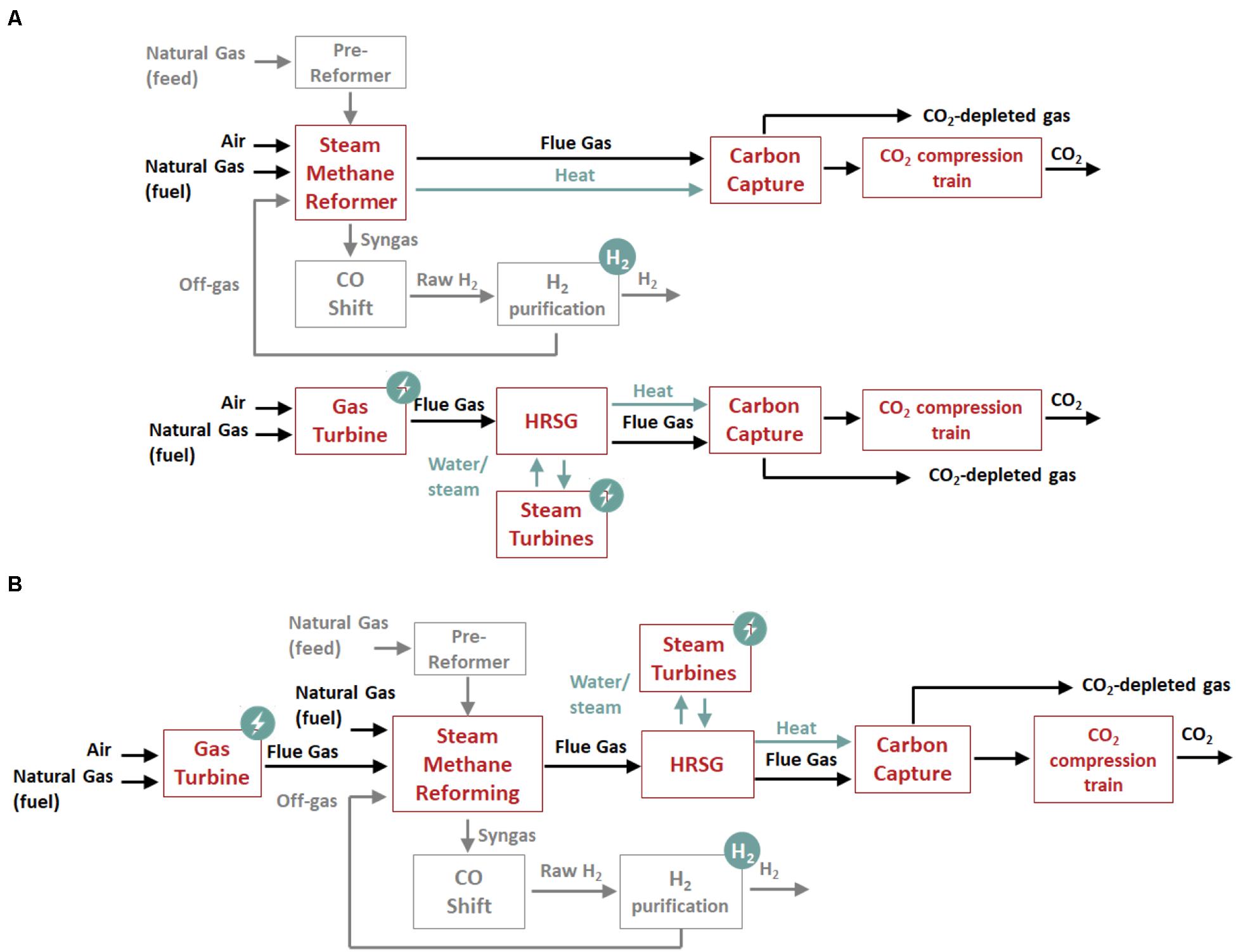
Figure 1. Simplified block flow diagram of the base configuration (A) and the integrated configuration (B).
The performance assessment of the thermodynamic integration is conducted for two reforming technologies widely considered for synthesis gas production in a hydrogen production plant:
• A steam methane reformer (SMR) with the endothermic reforming reactions being carried out in catalyst-filled tubes placed in a gas-fired radiative furnace as the source of energy. Radiation is the primary heat-transfer mechanism along with convection heat transfer from the furnace gas to the catalytic tubes to provide the thermal energy required for the reforming reactions. Typical hydrogen production volumes are between 2,000 and 300,000 Nm3/h (Corso, 2019).
• A gas heated reformer (GHR) or convective reformer consisting of a combustion chamber followed by a tubular reactor packed with catalyst. The steam reforming process is similar to the conventional SMR described above, but heat is mainly transferred by convection from the combustion gases to the catalyst-filled tubes (Wesenberg et al., 2007). Convective reformers are stated to allow a more compact design and higher efficiencies. It is possible to minimize steam generation in the process, resulting a reforming section without export of steam. Typical hydrogen production volumes are between 5,000 and 50,000 Nm3/h (Haldor Topsoe, 2007).
These two reforming technologies allow for investigation of a wide range of hydrogen production capacities and integration options for a reformer with different sizes of standard commercial gas turbine engines, i.e., a heavy duty gas turbine and an aeroderivative gas turbine. The selection of the appropriate standard gas turbine is based on the typical volume of exhaust flue gases and thus the oxygen content required for the integration with each hydrogen process with the size of the steam methane reformer and the gas heated reformer then matched to the GT based on the amount of heat released during combustion. An overview of the investigated configurations is presented in Table 1. They are compared in terms of net power output and thermal efficiency on the basis of the same hydrogen production. The hydrogen production volume of the SMR and GHR in the integrated configurations are respectively 3.5 and 2.5 higher than the largest commercial unit, at the time of writing, but there is a likely drive toward larger units, since worldwide hydrogen demand is expected to increase from 35 to 1,100 TWh per annum in 2030 (up to 1% of global primary energy demand), scaling up to 300 - 19,000 TWh per annum in 2050 (up to 8% of global primary energy demand), as reported in Committee on Climate Change [CCC] (2018).
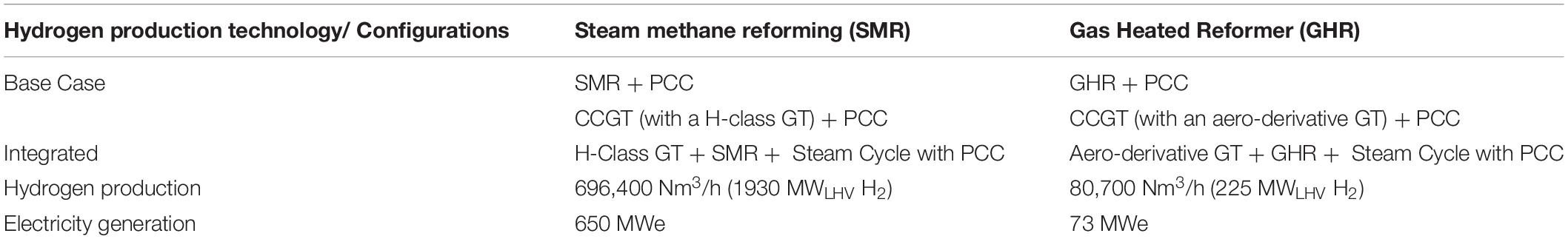
Table 1. An overview of the investigated configurations.
The reduction in size of the capture plant is evaluated in terms of number of absorber columns and packing volume. The base case configurations for an SMR and a GHR based hydrogen plant are described in Supplementary Appendices A, B
A Steam Methane Reforming Hydrogen Plant Integrated With a H-Class Gas Turbine Combined Cycle
Process Description of the Hydrogen Plant and the CCGT Power Plant Equipped With CO2 Capture
SMR Hydrogen Process and CCGT Power Plant
Figure 2 shows a schematic diagram of a purpose-built steam methane reformer (SMR) furnace where sequential combustion of natural gas and reformer tail gas takes place, using the excess oxygen in the gas turbine exhaust flue gas. The process flow diagram of the integrated configuration consisting of a purpose-built SMR for hydrogen production located downstream of a commercially available H-class gas turbine engine is illustrated in Figure 3. The hydrogen plant produces ca. 696,400 Nm3/h (16 kg/s) of H2 at 25 bar and 40°C.
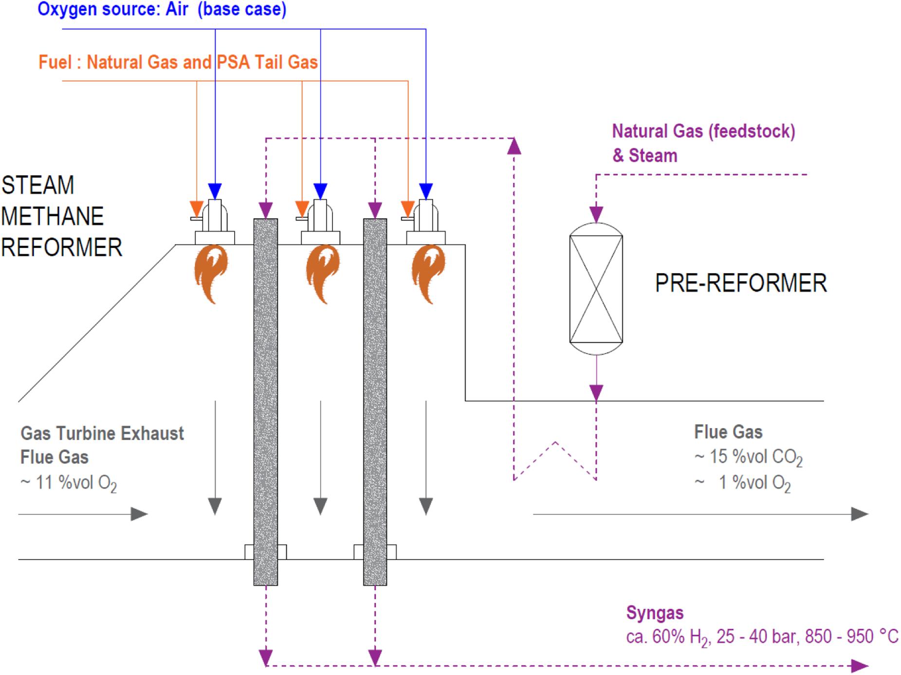
Figure 2. Schematic diagram of the sequential combustion of natural gas and tail gas in a steam methane reformer furnace using the excess oxygen in a gas turbine exhaust flue gas.
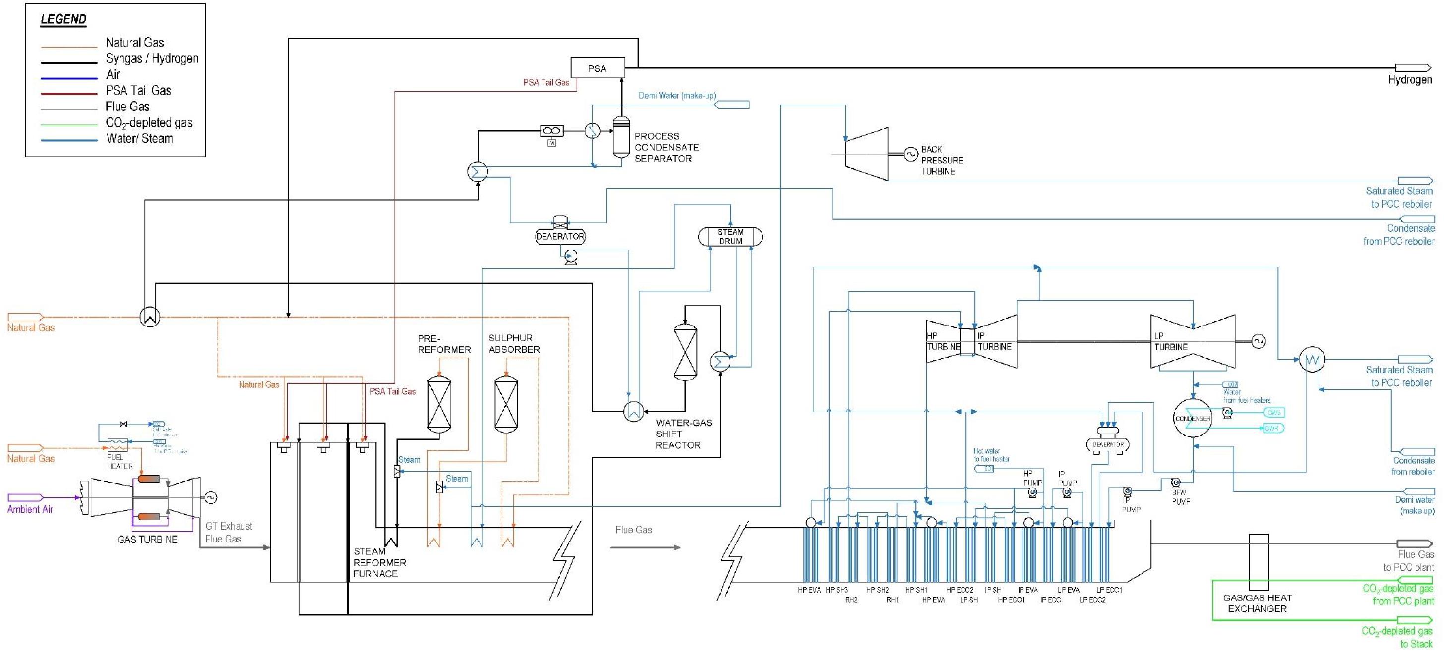
Figure 3. Process flow diagram of the integrated configuration consisting of a H-class gas turbine, a steam methane reforming hydrogen plant and a steam cycle with post-combustion CO2 capture.
The gas turbine exhaust flue gas is therefore used as the source of oxygen for the combustion of the tail gas from the hydrogen purification unit, as primary fuel, and natural gas, for additional fuel as required, in the burners of the SMR furnace. The heat released in the combustion is used to provide the sensible heat to increase the natural gas feedstock temperature up to the reaction temperature and the heat for the endothermic methane reforming process. The main heat transfer mechanism is radiation from the furnace walls and the flame itself, along with convection from the hot combustion gas to the catalyst-filled tubes.
The syngas production process is identical to that of the conventional SMR hydrogen plant of the base case configuration described in Supplementary Appendix A. A desulfurized and pre-heated natural gas stream is mixed with steam to achieve a steam to carbon ratio of 3 in the feed stream of the main reformer. Excess steam needs to be provided to drive the reforming reactions toward CO2 and H2 rather than CO and H2O, and to avoid thermal cracking of the hydrocarbons and coke formation. The mixture of natural gas and steam enters first the pre-reformer, an adiabatic reactor where light hydrocarbons, i.e., mainly C2 + and olefins, are fully converted to CO and H2. It then enters the catalyst-filled tubes of the main reformer at ca. 600 °C. Inside the catalytic tubes, methane reacts with steam at a relatively high temperature and moderate pressure of ca. 35 bar to generate synthesis gas, so called syngas, which contains essentially equilibrium proportions of H2, CO, CO2 and H2O.
The product gas from the reformer tubes at ca. 920°C is first cooled down to ca. 320°C in a waste heat boiler, since lower temperatures push the shift toward CO2 and H2. It is then fed to the high-temperature water-gas-shift (WGS) reactor, where steam converts most of the CO to CO2 and H2 over a bed of catalyst, producing a syngas with a residual CO concentration of ca. 3.6 vol%. The shifted syngas is then cooled down to ca. 35 °C, which is below its water dew point. Condensed water is recirculated back to the feed water circuit. Hydrogen is separated in the hydrogen purification unit by pressure swing adsorption (PSA) to recover typically 90% of the hydrogen at > 99.9 vol% purity. The PSA tail gas, containing mainly CH4, CO and CO2, is used as the primary fuel in the burners of the reformer furnace.
The flue gas leaves the reformer furnace at ca. 1260°C and sensible heat is recovered for preheating the natural gas feedstock and producing superheated steam at 400°C and 43 bar. Additional steam is generated from the syngas upstream and downstream of the WGS reactor. Part of the steam is used for the reforming process and the rest is exported to a back pressure steam turbine for electricity generation. In the steam turbine, superheated steam expands from 43 bar to 4 bar and it is then used to supply part of the reboiler duty required for solvent regeneration in the CO2 capture system. Two independent water/steam cycles are proposed, one for the hydrogen process and one for the power cycle, due to the higher steam purity required to drive the steam turbines of the combined cycle. Importantly, this steam cycle approach would also allow operation of the gas turbine without hydrogen production and operation of the SMR, under air-firing, without the gas turbine.
The remaining heat in the exhaust flue gas is recovered in a three-pressure level HRSG with reheater located downstream of the reforming section, which supplies steam at 179 bar, 44 bar and 3.7 bar to a subcritical triple pressure steam turbine train to generate electricity.
The flue gas exiting the HRSG is cooled down first in a gas/gas rotary heat exchanger, where heat is transferred to the CO2-depleted gas stream from the top of the absorber, and then in a direct contact cooler, entering the bottom of the absorber of the carbon capture plant at ca. 45°C saturated with water vapor.
CO2 Capture and Compression System
The integrated configuration is equipped with a single carbon capture system to remove CO2 from the resulting flue gas stream leaving the HRSG. One of the two carbon capture systems required in the reference configuration, i.e., one for the SMR based hydrogen plant and one for the CCGT power plant, therefore becomes redundant.
The carbon capture system consists of a conventional chemical absorption process using a 30 wt% monoethanolamine (MEA) aqueous solution as benchmark solvent for CO2 capture processes. The thermodynamic integration of the hydrogen production and electricity generation is obviously not solvent specific or carbon capture technology specific. A detailed description of the carbon capture plant and the technical design and operational parameters are included in Supplementary Appendix C.
The thermal energy for solvent regeneration is provided by steam from the power plant cycle. Superheated steam is extracted between the intermediate and low pressure turbine at 3.7 bar to overcome an estimated pressure drop of 0.7 bar. The steam is conditioned and supplied to the reboiler, which is designed for saturated steam at 3 bar and 133°C, with a temperature difference of 7°C. The rest of the steam expands in the LP steam turbine to the condenser pressure at 0.038 bar. A recirculated wet cooling system is considered with a cooling water supply temperature of 15°C and a temperature rise in the cooling water return limited to 10 °C.
The CO2-rich gas leaves the condenser at the top of the stripper column at 40°C and ca. 1.7 bar, with a CO2 purity of 95 vol% and is conditioned prior to transport and storage/utilization to achieve a CO2 purity of > 99 vol%. The stripper column pressure is optimized according to flue gas CO2 content to minimize the reboiler duty for each configuration. The CO2-rich gas stream is compressed up to the critical pressure (73.8 bar) in the compression train, which consists of three compression stages with intercooling and water separation between stages. Liquid phase CO2 at 73 bar and 28°C is pumped to 110 bar for transport and storage in supercritical/dense phase. A detailed description of the CO2 compression train is presented in Supplementary Appendix D.
Modeling Methodology
The optimization of the thermodynamic integration has the objective of minimizing the volume of the flue gas treated in the post-combustion carbon capture system and of enhancing heat recovery from the flue gas in the HRSG to maximize the steam production for power generation.
An integrated model of the power plant and the hydrogen plant equipped with CO2 capture and compression was developed in gPROMS Model Builder (PSE, 2019). It is a process modeling platform that allows creating customized models for each unitary operation, using the property method of Peng-Robinson as equation of state for mixtures of gases and the Steam Tables (IEAPWS-95) for water and steam. The process flow diagram as implemented in gPROMS is presented in Figure 3. The model of the carbon capture system based on chemical absorption with 30 wt% MEA solution is developed using gCCS library and gSAFT advanced thermodynamics to evaluate the physical properties of MEA aqueous solutions (Chapman et al., 1990, 1989; Bui et al., 2018).
A GE H-class gas turbine engine (GE 9HA.01) is considered in this work and it is modeled according to GE’s design and operating specifications available in the public domain (Matta et al., 2010; General Electric Thermal Power Generation, 2019). The gas turbine operates at a pressure ratio of 23.5, a turbine inlet temperature (TIT) of 1430°C and an air fuel ratio (AFR) of 37.2 on mass basis at ISO ambient conditions and 100% load, with a mechanical power output of 446 MWe and 43.2%LHV thermal efficiency. The flue gas exits the gas turbine at ca. 632°C with a flow rate of ca. 850 kg/s and an oxygen concentration of 11.3 vol%, and it is used for sequential combustion of PSA tail gas and natural gas in the SMR furnace.
The model of the SMR is developed based on the technical and operating parameters of a conventional SMR described in a report commissioned by the IEAGHG (2017a), with the process modified slightly for the purpose of the thermodynamic integration with subsequent heat recovery in a three-pressure level HRSG for steam generation. The pre-reformer is simulated as an adiabatic reactor and the reformer and the water-gas-shift reactor are simulated as equilibrium reactors based on a Gibbs energy minimization approach. The SMR hydrogen plant is sized to meet the following requirements:
• The gas turbine exhaust flue gas completely replaces the combustion air and an excess oxygen of 1 vol% (wet basis) is required in the combustion gas to ensure complete combustion. The amount of natural gas burnt as auxiliary fuel in the SMR furnace is accordingly evaluated.
• The amount of natural gas feedstock is set to achieve a hydrogen production volume of ca. 696,000 Nm3/h (16 kg/s), four times the hydrogen production volume of the SMR in the base case configuration (to match the size of the GT).
• The operating conditions in the catalytic-filled tubes are set at 912°C, with a steam to carbon ratio of 3 and a total pressure of 33.9 bar to achieve a methane conversion of 84% in the reformer (IEAGHG, 2017a). For the same values as in the base case equilibrium reactor and the same hydrogen production, the natural gas feedstock flow rate remains the same.
• A temperature of 600°C is set at the inlet of the catalytic-filled tubes. An energy balance in the furnace will define the flue gas exit temperature and therefore the pinch temperature in the reformer, defined here as the temperature difference between the process gas temperature at the inlet of the catalytic tubes, i.e., 600°C, and the furnace exit temperature.
The steam cycle downstream of the reformer section is modeled considering design and operating parameters from a study commissioned by the IEAGHG (2012). It consists of a subcritical three-pressure level HRSG, with double reheat and a screen evaporation section upstream of the high-pressure superheater and reheater surface, supplying steam to a triple pressure steam turbine. The screen evaporation section reduces the flue gas temperature down to ca. 850°C upstream of the superheater in order to maintain the tube metal temperature below acceptable limits. The pressure levels at the high, intermediate and low pressure drums are set at 179 bar, 44 bar and 3.7 bar respectively and the steam temperature to the HP and IP steam turbine cylinders is limited to 602 °C.
The CO2 capture plant is designed and operated to achieve a generic 90% overall CO2 capture level, i.e., 90% of the CO2 generated in the gas turbine and in the hydrogen process as the product of the reforming reactions and the combustion of natural gas and PSA tail gas is captured from the flue gas before exiting through the stack. Although this is not the focus of this article, higher capture levels up to 95 to 99.5% could be achieve if necessary, as reported in MHI (2019).
For the purpose of the comparative performance assessment between the integrated configuration and the base case configuration, the net power output, the net thermal efficiency and the reduction in the absorber size are reported. The net power output and the net thermal efficiency (ηth) are evaluated according to Equations (1) and (2) respectively, where is the gas turbine power output, is the back pressure turbine power output, is the steam turbine power output, is the auxiliary power consumption in the feed water and cooling water pumps, is the power consumption in the forced draft fan and solvent pumps of the carbon capture plant, is the power consumption in the CO2 compression train. The net thermal input takes into account the thermal energy in the natural gas streams used as fuel for the reformer burner and fuel for the gas turbine combustor .
The hydrogen production efficiency (ηH2) used for comparing configurations is evaluated according to Equation (3), where is the hydrogen mass flow rate, LHVH2 is the low heating value of hydrogen on mass basis, and is the thermal energy in the natural gas stream used as feedstock.
Results and Discussion
Overall Performance of the Integrated System
Since sequential combustion takes place in the burners of the reformer and the catalyst-filled tubes are located inside the flue gas duct, the performance of the gas turbine is not affected. It operates with a mechanical power output of 446 MWe and 43.2%LHV thermal efficiency at ISO ambient conditions and 100% load, with the assumption that the pressure drop across the reformer is compensated by the forced draft fan of the carbon capture plant.
The steam methane reformer is, however, designed for a change in the comburent composition. The oxygen concentration in the GT exhaust flue gas is 11.3 vol%, compared to 21 vol% in ambient air. A large volume of oxygen-containing flue gas is therefore necessary to supply the amount of oxygen for complete combustion with 1 vol% excess oxygen at the exit of the furnace. This results in a relatively low firing temperature compared to that in a conventional SMR. The firing temperature decreases from 1829°C in the base case configuration to 1526°C in the integrated configuration. Consequently, the contribution of thermal radiation decreases, increasing the convective heat transfer rate. Moreover, the reformer pinch temperature, defined here as the difference between the temperature of the process gas entering the catalytic tubes and the furnace exit temperature, decreases by 100°C to 538°C. The SMR furnace requires therefore to be designed accordingly for larger heat transfer surface areas to achieve the equilibrium temperature of 912°C that leads to a methane conversion of 84%. Although this has not been studied in detail in this article, the operation of gas heated reformer in Section “A Gas-Heated Reformer Integrated With an Aeroderivative Gas Turbine Combined Cycle” suggests that this is practically achievable. Figure 4 illustrates the flue gas temperature profile in the reforming section of the integrated configuration, which can be compared with Supplementary Figure A.3 for the reference reformer of the base case configuration.
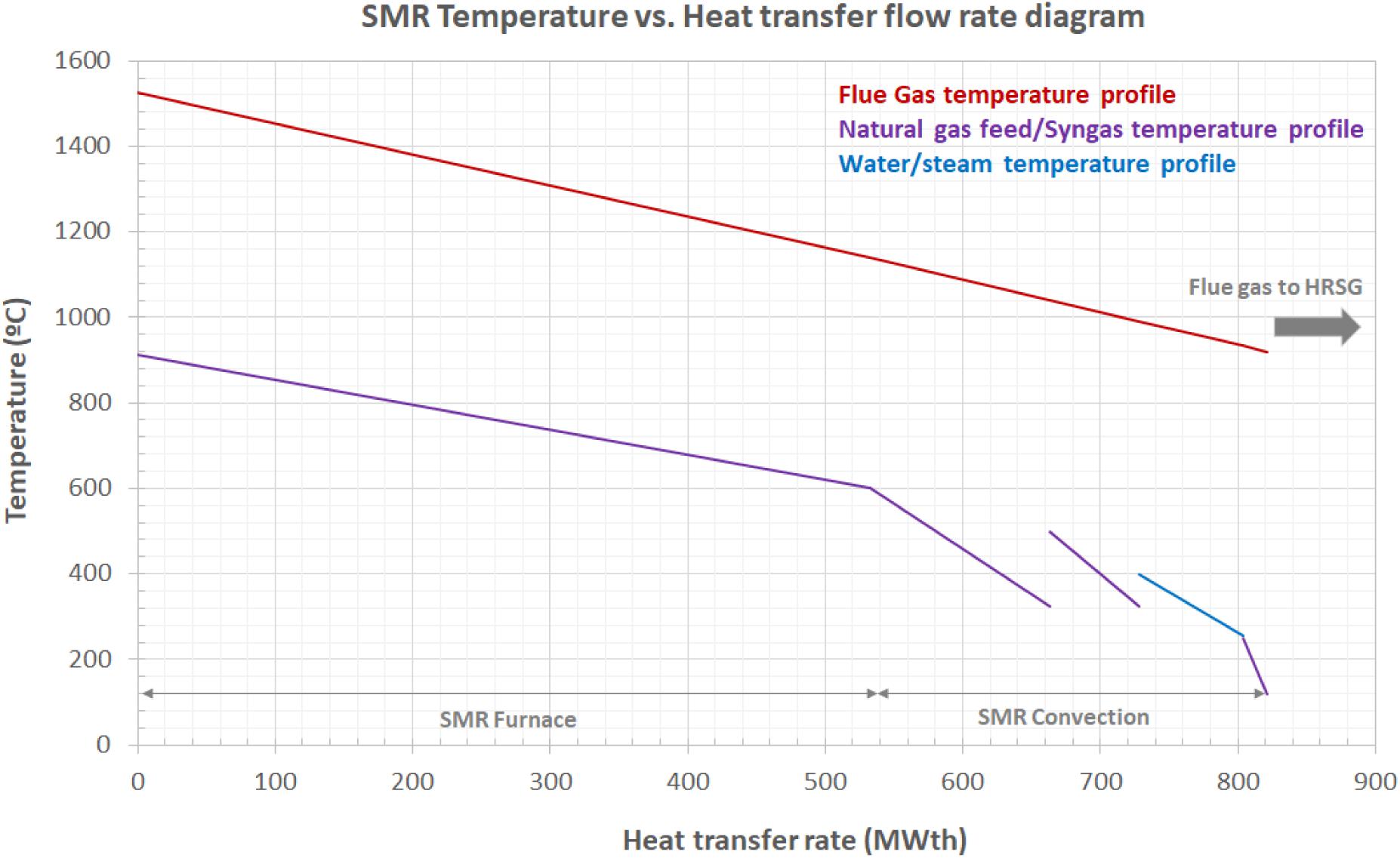
Figure 4. Temperature vs. heat transfer flow rate diagram in the steam methane reforming of the integrated GT-SMR-HRSG configuration.
In order to maximize the steam generation in the HRSG, the amount of steam produced is limited to the heat recovered from the hydrogen process upstream and downstream of the WGS reactor and, thus, the amount of steam exported to the back pressure turbine is smaller than in the reference hydrogen plant. The back pressure turbine power output is ca. 20 MWe in the integrated configuration compared to 90 MWe in the base case configuration. A larger volume of flue gas enters the HRSG at a higher temperature, i.e., 920°C compared to 630°C at the exit of the gas turbine of the reference CCGT power plant, allowing for a higher steam flow rate and hence for an increase in the steam turbine power output. Figure 5 illustrates the pinch temperature diagram in the HRSG, located immediately downstream of the SMR furnace in the integrated configuration, which can be compared with that of the HSRG of the reference CCGT power plant illustrated in Supplementary Figure A.4. Unlike in a conventional HRSG, a screen evaporation section is used to reduce the flue gas temperature from ca. 920°C to ca. 840°C, protecting the superheater tubes from excess temperatures.
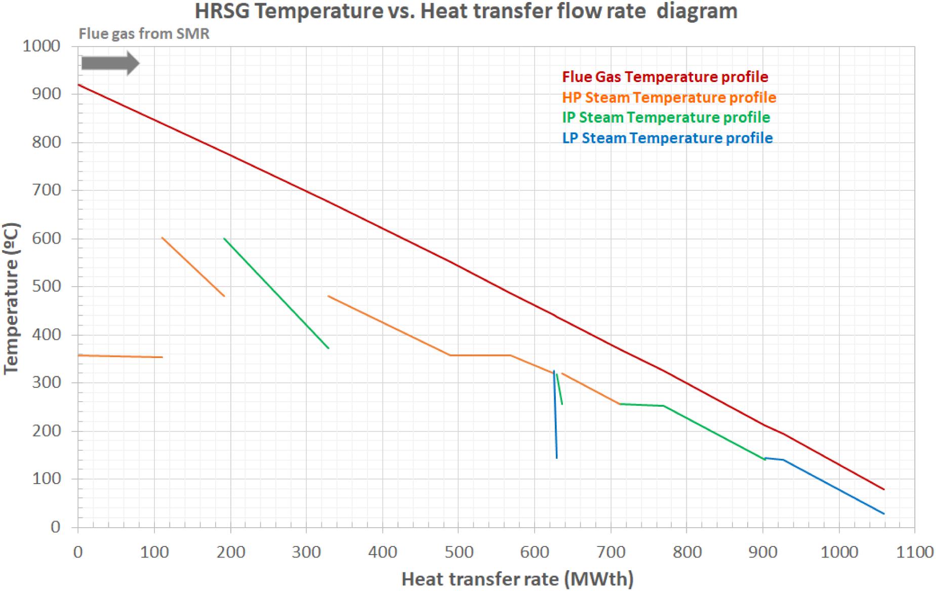
Figure 5. Temperature vs. heat transfer flow rate diagram in the heat recovery steam generation section of the integrated GT-SMR-HRSG configuration.
The net power output in the integrated system is 652 MWe with a natural gas thermal input of 1673 MWth on LHV basis, which results in a thermal efficiency of 38.9%LHV. This constitutes 34 MWe of additional power with an increase in efficiency of 4.9 perceptual points, compared to the based case configuration. Key performance parameters are presented in Table 2.
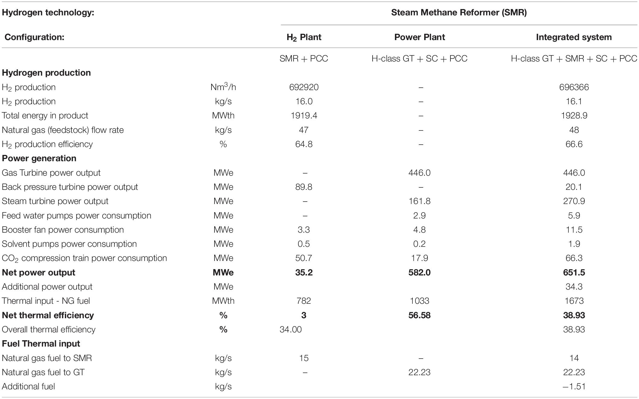
Table 2. Performance parameters of the integrated system consisting of a steam methane reformer downstream of a H-class gas turbine and of the hydrogen plant and the CCGT power plant of the base case configuration.
Effect on the CO2 Capture System
The integrated configuration results in a single CO2 emission source, and therefore a single carbon capture plant is required to treat the resulting flue gas stream of 970 kg/s with 14.8 vol% CO2 and 1 vol% excess oxygen. For water saturation conditions at 45°C at the inlet of the absorber, the CO2 concentration is 16.3 vol%, compared 10.5 vol% by mixing the two flue gas streams in the non-integrated configuration. One of the two carbon capture plants, one for the hydrogen plant and one for the CCGT power plant, in the base case configuration therefore becomes redundant, with a potential reduction in investment and operation costs associated to the CO2 capture system. The key performance parameters of the carbon capture plant are presented in Table 3.
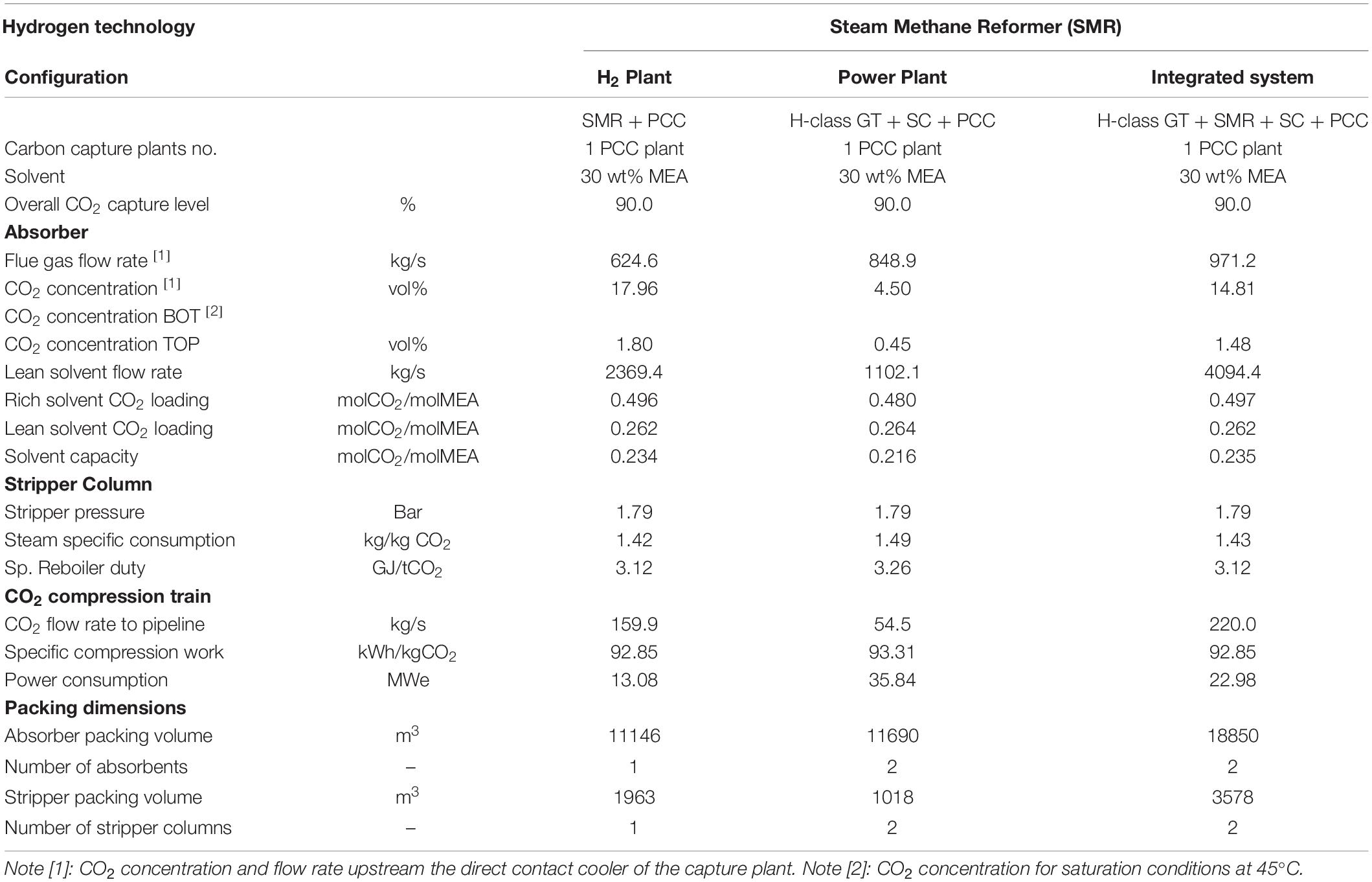
Table 3. Performance parameters of the carbon capture plant of the integrated system and of the hydrogen plant and the CCGT power plant of the base case configuration.
With the flue gas flow rate being approximately 34% lower than the total flow rate of the two flue gas streams from the CCGT power plant and from the SMR hydrogen plant in the base case configuration, a reduction in the absorber diameter is possible at constant gas velocity. In the integrated configuration, the capture plant comprises two absorber columns of 20 m internal diameter and 30 m packing height to operate at 80% of the flooding velocity and to achieve 90% CO2 capture rate. It results in a packing volume of approximately 18,850 m3, which constitutes a 17.5 vol% reduction compared to the total packing volume in the absorbers of the two carbon capture systems, i.e., one for the hydrogen plant and another for the CCGT power plant.
The high CO2 concentration in the flue gas entering the absorber leads to a higher driving force for mass transfer and displaces the equilibrium toward a higher CO2 loading in the rich solvent, moderately increasing the solvent capacity. Yet, according to the work of Li et al. (2011), most of the benefits occur from increasing CO2 concentration from 4 vol% to the nominal value of 9 vol%. Compared to the capture system of the CCGT power plant of the base case configuration, the CO2 loading of the rich solvent leaving the bottom of the absorber increases marginally from 0.480 molCO2/molMEA to 0.496 molCO2/molMEA in the integrated configuration. The optimal lean loading minimizing reboiler duty is 0.262 molCO2/molMEA. The moderate increase in solvent capacity and the lower solvent flow results in a reduction of the specific reboiler duty of approximately 4.3%, from 3.26 GJ/tCO2 in the capture plant of the CCGT power plant, to 3.12 GJ/tCO2, in the capture plant of the integrated configuration.
A Gas-Heated Reformer Integrated With an Aeroderivative Gas Turbine Combined Cycle
A gas heated reformer or convective steam reformer is a compact alternative to the conventional bottom, top, terrace wall or side fired steam reformer furnaces for the production of synthesis gas from natural gas. Convective reformers were developed to improve the energy efficiency and reduce the investment costs due to their compact design and modularization, and they are preferred for smaller capacities up to 50,000 Nm3/h (Wesenberg et al., 2007). Thermal convection is the dominant heat transfer mechanism in the tubular reactor and, thus, the results of integration with a CCGT power plant are of particular interest. For the purpose of this study, the use of a GHR allows a wider range of hydrogen production capacities to be explorer, with the use of different gas turbine engines in the integrated configuration.
Gas heated reformers are designed and sized to maximize the hydrogen yield whilst minimizing the fuel consumption and the steam production. The integration of a stand-alone GHR with a post-combustion carbon capture system using flue gas scrubbing technology would therefore require an external source of steam to provide the heat for solvent regeneration.
Process Description of the GHR Based Hydrogen Plant and the CCGT Power Plant Equipped With CO2 Capture
GHR Hydrogen Process and CCGT Power Plant
The process flow diagram of the integrated configuration consisting of a conventional gas heated reformer (GHR), as illustrated in Figure 6, located downstream of a commercially available aeroderivative gas turbine. The integrated system is illustrated in Figure 7. The hydrogen plant procures ca. 80,750 Nm3/h (1.86 kg/s) of H2 at 25 bar and 35°C. As previously discussed, the gas turbine exhaust flue gas is used as the source of oxygen for the combustion of tail gas from the hydrogen purification unit, as primary fuel, and natural gas, as auxiliary fuel, replacing the combustion air in the burners of the reformer combustion chamber. The combustion gas at approximately 1200°C then enters the convective reformer which consists of a multi-tubular reactor where heat is mainly transferred by convection from the hot flue gas stream to the catalyst-filled tubes, as shown in the schematic diagram of Figure 6. Unlike in the furnace of a fired SMR, convective heat transfer is the dominant form of heat transfer in the reactor.
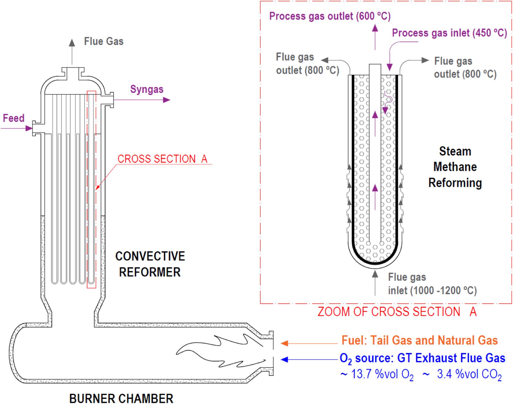
Figure 6. Schematic diagram of the gas heated reformer in the integrated configuration.
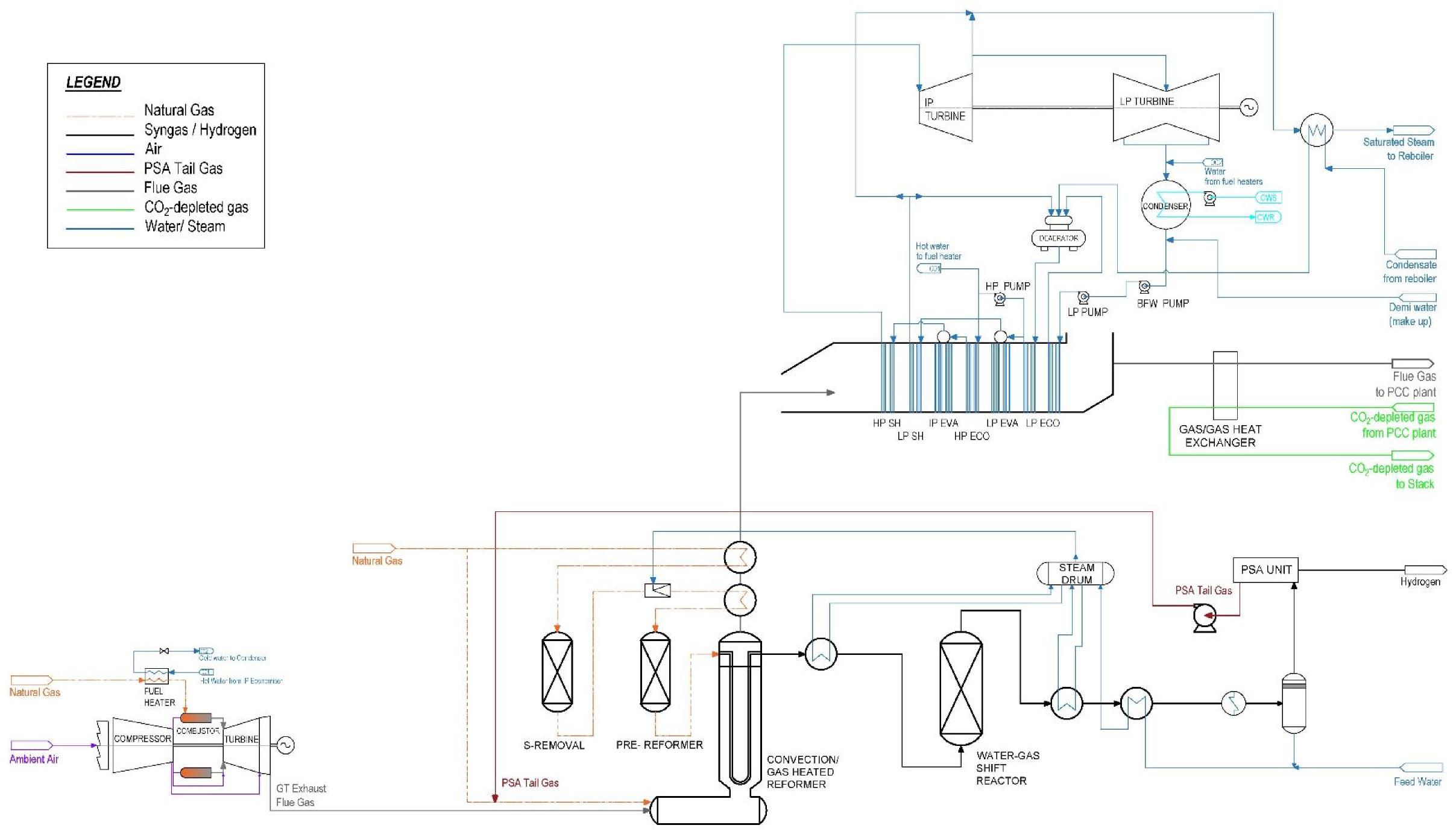
Figure 7. Process flow diagram of the integrated configuration consisting of an aeroderivative gas turbine, a gas heated reformer and a steam cycle with post-combustion capture.
The heat released in the combustion supplies the sensible heat required to increase the natural gas feedstock temperature up to the equilibrium temperature of approximately 850°C and the heat for the endothermic reforming reactions. The remaining sensible heat in the flue gas is used first to pre-heat the feed stream containing natural gas and steam and then to generate steam for power generation in an HRSG located downstream of the convective reformer. Superheated steam is supplied to a double pressure steam turbine generator at 54 bar and 3.7 bar. Unlike H-class gas turbines, aeroderivative gas turbines are typically integrated with a two-pressure level HRSG since the smaller power output drives the economics toward a lower capital cost system.
With the exception of possible changes in the combustion taking place in the burner of the combustion chamber, the remaining of the hydrogen process is consistent with an air-fired conventional gas heated reformer of the base case configuration described in Supplementary Appendix B.1. A desulfurized and pre-heated natural gas stream is mixed with steam. The steam flow rate is set to achieve a steam to carbon ratio of 3 in the reformer feed to avoid thermal cracking of the hydrocarbons and coke formation. The mixture of natural gas and steam is further preheated and enters the gas heated reformer at ca. 450°C, flows downward through the catalyst bed and reaches equilibrium at the bottom of the reactor. The reformed gas enters the center tube and continues upward leaving the reactor at ca. 600°C to enter the heat recovery section.
In the air-fired GHR of the base case configuration, a methane conversion of 73% is possible with a steam to carbon ratio of 3, an equilibrium temperature of 850°C and a total pressure of 33.9 bar. The introduction of sequential combustion requires modifications to the process to accommodate for changes in the composition of the comburent with a higher CO2 and H2O concentration than in ambient air. The reactor is therefore designed for the same carbon ratio and total pressure, yet for a lower equilibrium temperature of ca. 815°C. A lower equilibrium temperature leads to a lower methane conversion, shifting the chemical equilibrium, which leads to a higher volume of recycled PSA tail gas with a higher calorific value sent to the burner of the GHR. Although this lowers the specific hydrogen production per unit of volume of fuel, it has the advantage of increasing the steam generation and meet the steam requirements in the capture system for high CO2 capture rates.
The product gas from the steam reformer, containing equilibrium amounts of H2, CO2, CO and CH4, is then cooled down and fed to the WGS reactor where steam converts most of the CO to CO2 and H2 over a bed of catalyst, producing a syngas with a residual CO concentration of ca. 1 vol%. The raw hydrogen steam is fed to the hydrogen purification system by PSA to recover typically 90% of the hydrogen at > 99.9% purity. The PSA tail gas, containing mainly CH4, CO2 and CO, is recirculated to be used as the primary fuel in the combustion chamber.
Sensible heat is recovered from the reformed gas stream upstream and downstream of the WGS reactor to produce saturated steam at 42.3 bar and 254°C. The waste heat recovery system is typically designed to produce only the steam required for the reforming reactions, unlike in a conventional steam methane reformer where more steam is produced for co-generation. Equipped with carbon capture, a stand-alone hydrogen plant with a GHR would therefore need to import steam or to generate team on-site in an ancillary boiler or a combined heat and power (CHP) plant.
CO2 Capture and Compression System
The CO2 capture system and compression train are size according to the flow rate of combustion gas and CO2 flow, using the principles described in Section “CO2 Capture and Compression System.” The reader is referred to Appendices C and D for further details and relevant design and operational parameters.
Modeling Methodology
Customized models for each unit of the integrated gas heated reformer are developed in gPROMS Model Builder (PSE, 2019) using the library and the thermodynamic models described in Section “Modeling Methodology.” The process flow diagram as implemented in gPROMS is presented in Figure 7.
The model of the GHR reformer is based on the technical and operation specifications reported in a Haldor Topsøe’s report for the 6,000 Nm3/h Topsøe low-energy HTCR hydrogen plant at BorsodChem MCHZ’s facilities in Ostrava in the Czechia (Haldor Topsoe, 2007). The reformer and the WGS reactor are simulated as equilibrium reactors based on Gibbs energy minimization approach.
The gas turbine upstream of the gas heated reformer is a GE’s LM6000 aeroderivative gas turbine modeled according to GE’s design and operation specifications available in the public domain (Badeer, 2000; General Electric Thermal Power Generation, 2017). The gas turbine engine operates at a pressure ratio of 30, a turbine inlet temperature (TIT) of 1250°C and an air fuel ratio (AFR) of 50 on mass basis at ISO ambient conditions and 100% load, with a power output of 57 MWe and a thermal efficiency of 42.6%LHV. An exhaust flue gas flow rate of 148 kg/s, exiting the gas turbine at 490°C and with oxygen concentration of 13.7 vol%, is used as the source of oxygen for the combustion of PSA tail gas and natural gas in the combustion chamber of the GHR.
The size and flow rate of the GE LM 6000 is compatible with the mass balance and energy balance of sequential combustion in the combustion chamber and the reactor of a gas heated reformer. An energy balance in the reformer allows to determine the maximum possible hydrogen production of ca. 80,750 Nm3/h (1.86 kg/s), and the performance comparison with the air-fired GHR in the base case configuration is conducted on the basis of the same hydrogen production capacity.
The steam cycle is modeled on the basis of design parameters from the report commissioned by the IEAGHG (2012). As previously discussed, the shared carbon capture system in the integrated configuration is sized for a 90% CO2 capture rate.
Key Metric for Comparative Assessment With the Base Case Air-Fired GHR Hydrogen Plant With CO2 Capture
Since the gas heated reformers are designed to minimize steam production, they are not particularly suited for CO2 capture as stand-alone units, unless an external source of steam provides heat for the solvent regeneration. In the base case configuration with an air-fired GHR, steam is generated from heat recovery from the flue gases, yet additional steam extraction from the combined cycle is needed. Steam extraction from the combined cycle therefore supplies the thermal energy for the two carbon capture plants.
Limited steam availability in the combined cycle results in an overall CO2 capture rate of 84.5%. In this instance, the absorber columns are respectively sized for 90% capture rate from the CCGT flue gas and 82% capture rate from the GHR flue gas, although other permutations would be possible. The overall CO2 capture rate is also directly determined by the size of the aeroderivative gas turbine and the hydrogen production volume, 57 MWe and 80,750 Nm3/h in this case. The reader is referred to Supplementary Appendices B.1, B.2 respectively for all relevant details on the technical design and operating parameters of the hydrogen plant and the CCGT power plant equipped with their respective carbon capture systems in the base case configuration.
Results and Discussion
Overall Performance of the Integrated System
Since the aeroderivative gas turbine is located upstream of the GHR, the operation of the gas turbine is unaffected and operates with a power output of 57 MWe and 42.6%LHV thermal efficiency at ISO ambient conditions and 100% load, with, as previously stated, the assumption that the additional pressure drop in the reformer is compensated by the forced draft fan of the carbon capture plant.
The design and operation of the GHR deviates, however, from the design conditions for air-firing. The relatively low oxygen concentration in the GT exhaust flue gas, i.e., 13.7 vol% compared to 21 vol% in ambient air, results in a large volume of flue gas to supply the amount of oxygen needed for complete combustion of the PSA tail gas and natural gas, and to ensure flame stability. Unlike SMRs were the excess oxygen level is as low as 1 vol%, gas heated reformers operate with much higher excess air resulting in a 8 vol% excess oxygen at the exhaust, as indicated in Supplementary Appendix B.1. With sequential combustion, the excess oxygen at the exit of the GHR combustor chamber is ca. 6.7 vol%.
Due to the large volume of flue gas, the combustion chamber exit temperature and, thus, the temperature of the combustion gas entering the convective reformer is lower than 1200°C, i.e., the combustor exit temperature in a stand-alone GHR with air-firing. This results in a lower equilibrium temperature in the reformer for a given heat transfer area and a given pinch temperature, defined here as the difference between the combustion gas temperature and the equilibrium temperature. Although the lower equilibrium temperature shifts the equilibrium toward a lower hydrogen yield, the content of unreacted methane in the PSA tail gas increases, raising the fuel heating value and thus the temperature of combustion.
Ultimately, the operating conditions and the reactor equilibrium temperature are optimized so that enough steam is produced in the HRSG to achieve a CO2 capture rate of 90% for a hydrogen production of ca. 80,750 Nm3/h. Using as the comburent the gas turbine flue gas with an exhaust flue rate of 148 kg/s and an excess oxygen of 13.5 vol%, the GHR operates at a combustion gas temperature of 1115°C and an equilibrium temperature of 815°C. The relatively small pinch temperature of 300°C would require increasing the heat transfer area compared to an air-fired GHR with a pinch temperature of 350°C. Due to the smaller methane conversion in the catalytic tubes, the natural gas flow rate used as feedstock increases from 5.9 kg/s to 6.6 kg/s.
Sequential combustion of additional fuel in a GT exhaust flue gas also leads to a higher temperature of the flue gas entering the heat recovery section. The flue gas enters the HRSG at ca. 724°C, increasing the rate of steam flow and hence the steam turbine power output. The maximum steam temperature is, however, limited to a typical 600°C at the inlet of the high pressure steam turbine cylinder. The temperature profile along the flue gas pathway is illustrated in Figures 8, 9. Figure 8 shows the temperature pinch diagram of the reformer and Figure 9 shows the temperature pinch diagram of the heat recovery steam generator. For a hydrogen production of ca. 80,750 Nm3/h and 90% overall CO2 capture rate, the integrated configuration of a GHR and a CCGT with an aeroderivative gas turbine operates at 73 MWe power output and presents a thermal efficiency of 54.7%LHV. Key performance parameters are included in Table 4.
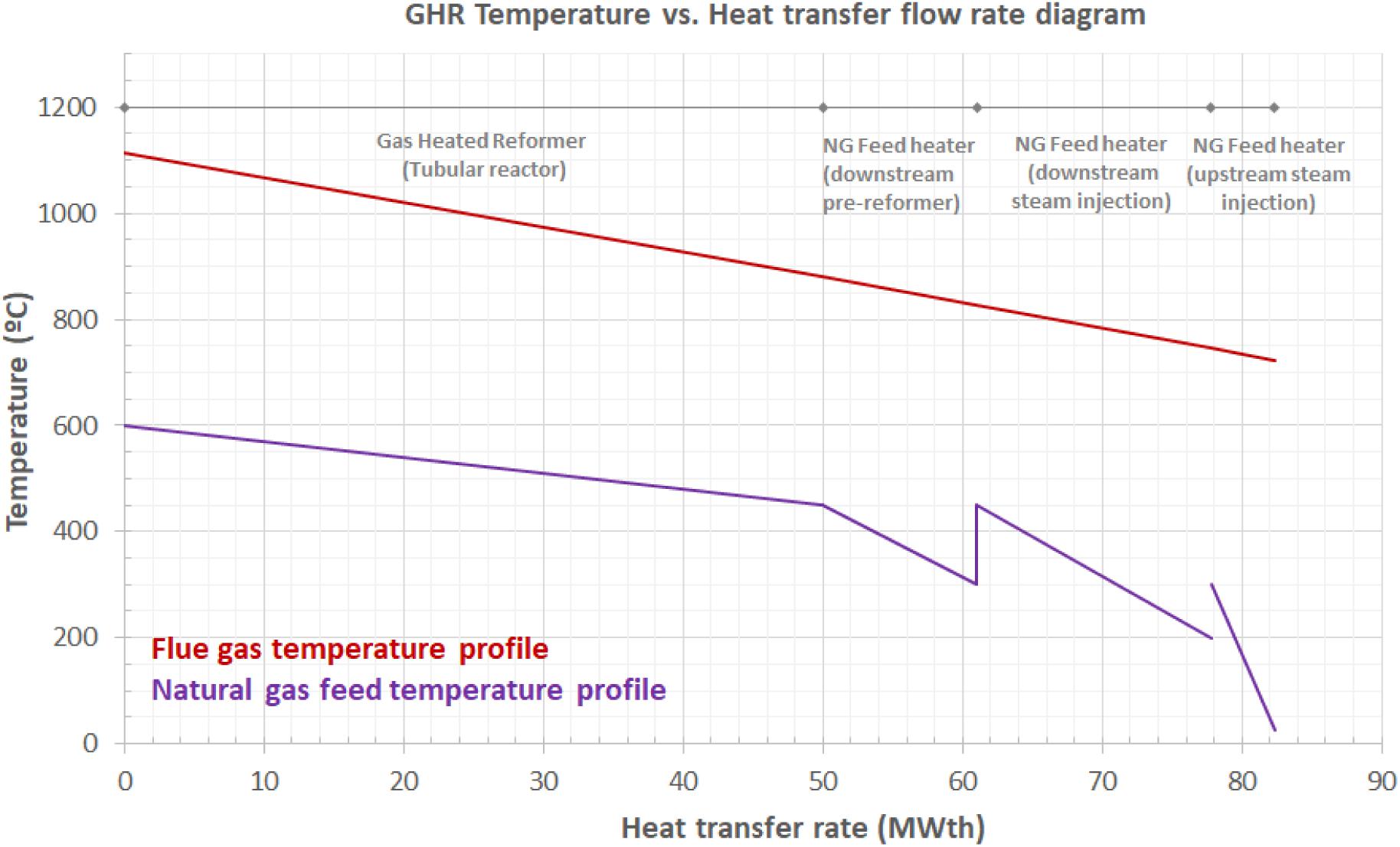
Figure 8. Temperature vs. heat transfer flow rate diagram in the reformer of the integrated configuration consisting of a aeroderivative gas turbine and a gas heated reformer, for 90% CO2 capture level in the post-combustion carbon capture system.
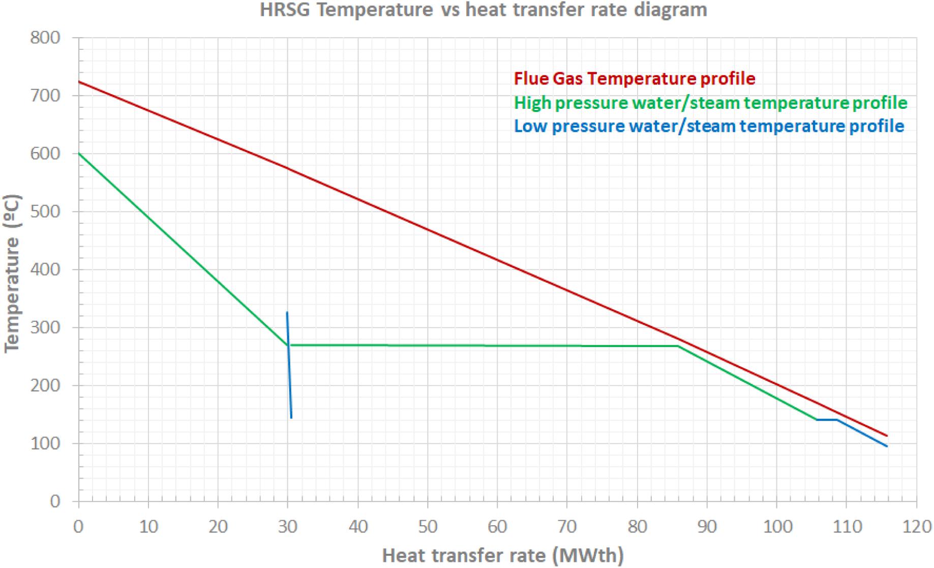
Figure 9. Temperature vs. heat transfer flow rate diagram in the heat recovery steam generation section of the integrated configuration consisting of a aeroderivative gas turbine and a gas heated reformer, for 90% CO2 capture level in the post-combustion carbon capture system.
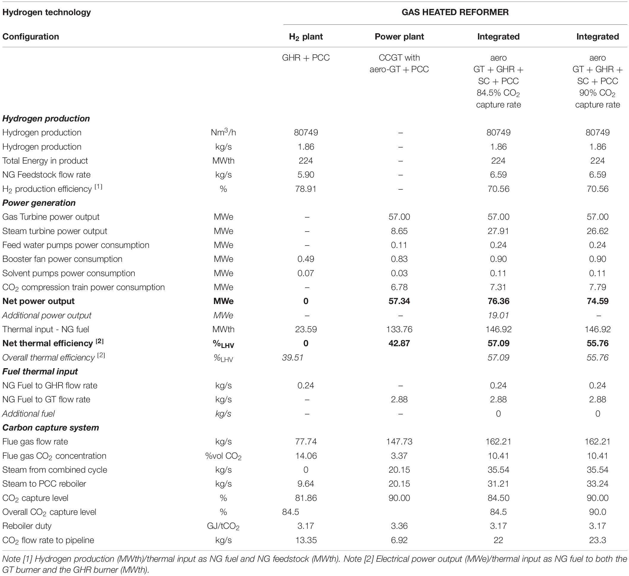
Table 4. Performance parameters of the hydrogen plant with a gas heated reformer and the CCGT power plant for both the base case configuration and the integrated configuration.
In order to conduct the comparative performance assessment on a consistent basis, two cases of the integrated configuration are reported in Table 4. The first case operates at an overall CO2 capture rate of 84.5%, i.e., identical to the highest possible capture rate achievable in the base case configuration using the remaining steam from the CCGT power plant. This level of capture is unlikely to be acceptable and is used solely for the purpose of a rigorous comparison on the basis of capture levels. The second case achieves a nominal 90% CO2 capture rate.
For the overall CO2 capture rate of 84.5%, the integrated configuration presents a higher net power output of 76.4 MWe due to the increase in the steam turbine power output, and a higher net thermal efficiency of 57.1%LHV, compared to 57.3 MWe and 39.5%LHV in the base case configuration. Key parameters for the performance assessment comparison of the two configurations are presented in Table 4.
In the integrated system with sequential combustion and 90% capture, the hydrogen production is ca. 80,750 Nm3/h, the power output is 74.6 MWe and the net thermal efficiency is 55.8%LHV. An increase in natural gas feedstock flow rate of ca 10% reduces the H2 production efficiency in the integrated system. The increase is necessary to increase steam production in the HRSG to provide additional low-pressure steam for the capture plant. This is achieved by a reduction of the equilibrium temperature in the reformer, making unreacted CH4 available in the tail gas from hydrogen production in the fuel to the GHR combustion chamber and enhancing the heat recovery from the exhaust flue gas at a higher temperature for steam generation.
Effect on the CO2 Capture System
Since the integrated configuration results in a single CO2 emission source, a single carbon capture plant is required to treat the resulting flue gas stream of 162 kg/s with 10.4 vol% CO2 and 6.7 vol% excess oxygen. Similarly to the thermal integration explained in Section “Results and Discussion,” the flow rate of the resulting flue gas with sequential combustion is therefore 28% smaller than in the base case configuration and the integration allows for a smaller total cross-section of the absorber in the capture plant.
The CO2 concentration in the flue gas is higher than the concentration that would result from mixing the two flue gas stream from the gas turbine engine and the reformer, i.e., 10.9 vol% CO2 compared to 6.9 vol% CO2 for a flue gas saturated at 45°C. It allows operation at a higher rich solvent loading of 0.49 molCO2/molMEA, resulting in a moderately higher solvent working capacity of 0.225 molCO2/molMEA. The specific reboiler duty is ca. 3.17 GJ/tCO2, similar to that in the capture plant for the GHR of the base case configuration, which is supplied by steam extracted from the combined cycle.
The technical design and operation parameters of the carbon capture system of the integrated configuration for a 90% overall CO2 capture rate are presented in Table 5. In addition to an increase of 19% net power output at constant hydrogen production, the other major benefit of the integrated configuration for a GHR is that a nominal 90% CO2 capture rate is now achievable unlike a much lower 84.5% capture rate without sequential combustion.
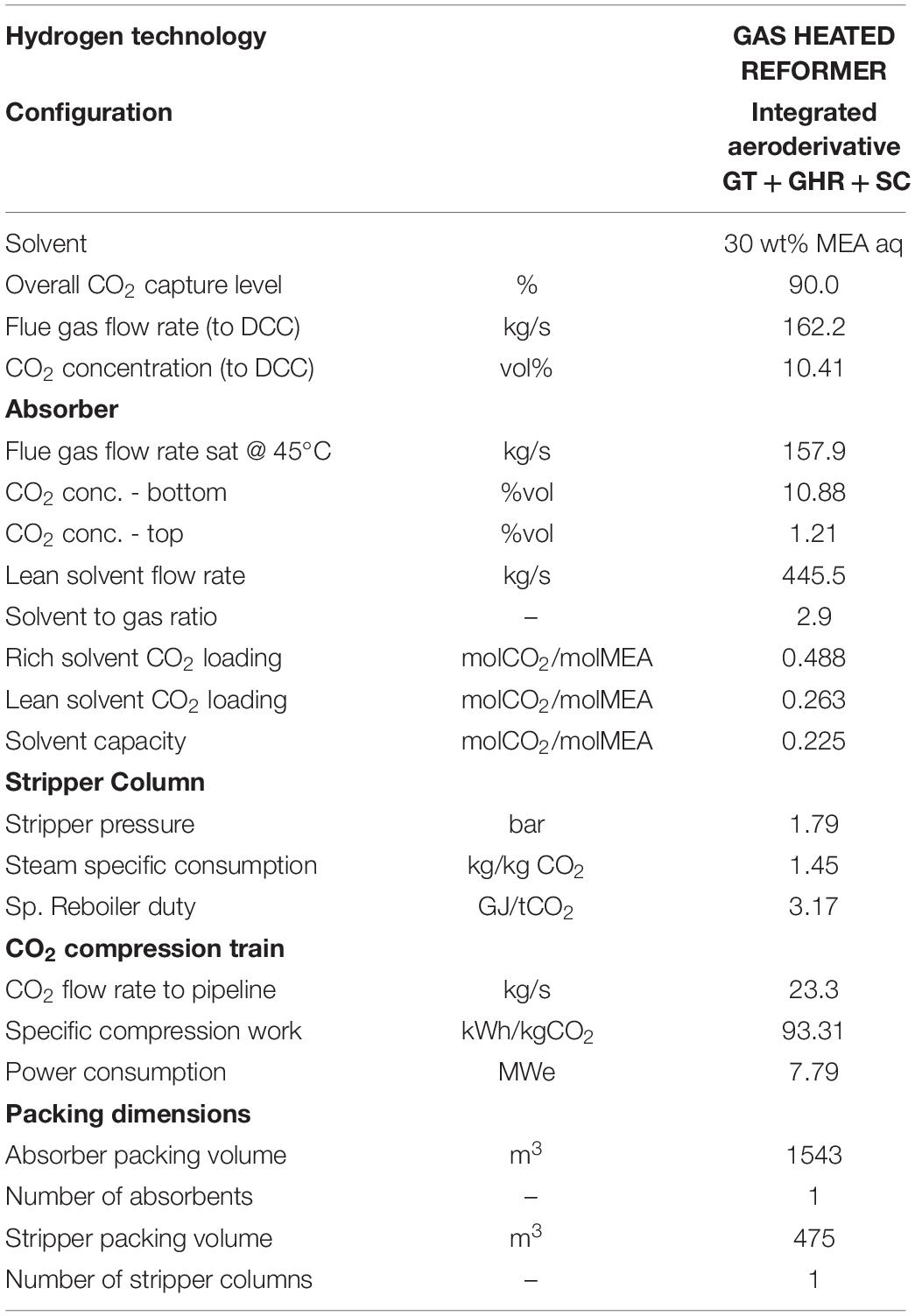
Table 5. Performance parameters of the shared CO2 capture system for a hydrogen plant with a GHR and a CCGT with an aeroderivative gas turbine.
Conclusion
Sequential combustion of natural gas in the exhaust flue gas of a gas turbine is proposed for the first time in this work to reduce the capital and operating cost of post-combustion CO2 capture (PCC) in hydrogen production via steam methane reforming integrated with in electricity generation using combined cycle gas turbine (CCGT) power plants.
Effective thermodynamic integration significantly increases net power output in at constant hydrogen production volume, reducing operating costs, whilst the use of a shared CO2 capture system is expected to contribute to significant capital cost reduction.
A newly developed rigorous model in gPROMS of gas turbine power generation systems integrated with examples of two hydrogen production technologies quantifies the step change in thermal efficiency and hydrogen production efficiency. It uses a conventional 30 wt% MEA capture process as a generic capture technology to quantify the reduction in size of absorber columns, the most capital intensive part of solvent-based post-combustion capture systems. The thermodynamic integration of sequential combustion between hydrogen production and power generation is, however, not solvent specific or capture technology specific and are applicable to other processes of post-combustion CO2 capture.
Two hydrogen production technologies, a conventional steam methane reformer (SMR) and a gas heated reformer (GHR), cover a wide range of hydrogen capacities, and in the example cases these are thermodynamically integrated with standard commercially available gas turbine engines, selected on the basis of their exhaust gas flow rate. When sequential combustion of natural gas, mixed with the tail gas from hydrogen separation, in the gas turbine exhaust gas takes place in the burner of the reformers, a single CO2 emission source with significantly lower flow rates by 34%, in the SMR, and by 28%, in the GHR, reduces the number of absorber columns compared to equivalent non-integrated systems. In addition, the flow rate and the temperature of the flue gas entering the heat recovery steam generator (HRSG) increase, leading to additional steam production for electricity generation.
The conventional SMR is located downstream of an H-class gas turbine engine followed by a three-pressure level HRSG, supplying steam for power generation in the combined cycle, and a capture plant with two absorber columns. The integrated system produces ca. 696,400 Nm3/h of H2 with a net power output of 652 MWe at a net thermal efficiency of 38.9%LHV. This corresponds to 34 MWe of additional power output, increasing efficiency by 4.9% points, and makes one absorber column redundant, compared to the equivalent non-integrated system producing the same volumes of H2. A CO2 concentration of 15 vol% allows effective operation of the 30 wt% MEA capture process at high solvent capacity, resulting in a reduction of absorber structured packing volume of 18% and a lower thermal energy for solvent regeneration by 4.3%.
The dedicated GHR is located downstream of an aeroderivative gas turbine engine followed by a two-pressure level HRSG, supplying steam for power generation in the combined cycle, and capture plant with one absorber column. The integrated system produces ca. 80,750 Nm3/h of H2 with a net power output of 73 MWe and a net thermal efficiency of 54.7%LHV. This corresponds to 13 MWe of additional power output, increasing efficiency by 13.5% points, and reduces the number of absorber columns necessary from two to one, compared to the equivalent non-integrated system producing the same volumes of H2.
The article also presents new insights for the design and operation of reformers integrated with gas turbines. First, sequential combustion enables additional steam production in the gas turbine/GHR system to achieve CO2 capture rates of 90%, or higher if necessary, compared to 84.5% in the equivalent non-integrated system. This is achieved by lowering the reactor temperature to increase the non-reacted methane concentration in the recirculated tail gas. Second, the operation of the gas turbine engine is unaffected since sequential combustion takes place in the reformer furnace or combustion chamber. This would make operating the gas turbine, HRSG and capture when the reformer is turned off possible.
The reformer is, however, designed for a change in the comburent composition and, in the case of a SMR, an increase of convective heat transfer rate over the radiative heat transfer rate. The lower oxygen concentration in the gas turbine exhaust flue gas, i.e., 11.3 vol% in a H-class gas turbine and 13.7 vol% in an aeroderivative gas turbine, compared to 21 vol% in ambient air, results in larger flow rates to supply the necessary amount of oxygen. This leads to a lower firing temperature and, thus, a smaller pinch temperature in the reformer, reducing the driving force for heat transfer. A large heat transfer surface area is likely to be required in the catalytic tubes of the reformer to maintain the equilibrium temperature at the design values and achieve a high hydrogen yield. Further work would be required to examine the operation of the reformer and the capture plant when the gas turbine is turned off.
These are important design considerations, to allow for flexible operating strategies for the generation of low-carbon hydrogen independently of low-carbon electricity, and vice-versa, when it makes economic sense to do so. Designing for flexible operation could be used to achieve further cost reduction via an increase of the utilization factor of the CO2 capture plant, since in future energy systems, seasonal variation in demand for hydrogen may indeed follow, to some extent, the seasonal patterns currently observed for natural gas, whilst electricity is expected to continue to be traded as a volatile commodity on a daily or hourly basis.
Data Availability Statement
All datasets generated for this study are included in the article/Supplementary Material.
Author Contributions
JG, ML, and LH conceived the present idea. LH developed the model and performed the simulations and wrote the manuscript with support from ML and HC. ML and JG contributed to the discussion of the results and the findings. ML, JG, and HC contributed to the final manuscript. All authors provided critical feedback and helped shape the research, analysis and manuscript.
Funding
The work presented in this manuscript is part of the research core program on capture of the UK Carbon Capture and Storage Research Centre (UKCCSRC), funded by the EPSRC (EP/P026214/1).
Conflict of Interest
The authors declare that the research was conducted in the absence of any commercial or financial relationships that could be construed as a potential conflict of interest.
Supplementary Material
The Supplementary Material for this article can be found online at: https://www.frontiersin.org/articles/10.3389/fenrg.2020.00180/full#supplementary-material
Abbreviations
CCGT, combined cycle gas turbine; CCS, carbon capture and storage; CCUS, carbon capture, utilization and storage; GHR, gas heated reformer; GT, gas turbine; HP, high pressure; HRSG, heat recovery steam generation; IP, intermediate pressure; LHV, low heating value (MJ kg–1); LP, low pressure; ηH2, hydrogen production efficiency (%); ηth, thermal efficiency (%); , mass flow rate (kg/s); PCC, post-combustion CO2 capture; PSA, pressure swing adsorption; , heat input (MWth); SC, steam cycle; SMR, steam methane reformer; ST, steam turbine; VSA, vacuum swing adsorption; , power output/power consumption (MWe); WGS, water-gas-shift.
References
Air Products (2011). Texas Carbon Capture and Sequestration Project [WWW Document]. Available at: http://www.airproducts.com/company/news-center/2011/05/0526-air-products-signs-two-agreements-for-texas-carbon-capture-and-sequestration-project.aspx.
Badeer, G. H. (2000). GE aeroderivative gas turbines – Design and operating features. GE power Syst. GER-3695E, 1–20.
BEIS, (2018). Delivering Clean Growth: CCUS Cost Challenge Taskforce Report. London: Department for Business, Energy and Industrial Strategy.
Billet, R., and Schultes, M. (1993). Predicting mass transfer in packed columns. Chem. Eng. Technol. 16, 1–9. doi: 10.1002/ceat.270160102
Bui, M., Flø, N. E., de Cazenove, T., and Mac Dowell, N. (2020). Demonstrating flexible operation of the technology centre mongstad (TCM) CO2 capture plant. Int. J. Greenh. Gas Control 93:102879. doi: 10.1016/j.ijggc.2019.102879
Bui, M., Tait, P., Lucquiaud, M., and Mac Dowell, N. (2018). Dynamic operation and modelling of amine-based CO2 capture at pilot scale. Int. J. Greenh. Gas Control 79, 134–153. doi: 10.1016/j.ijggc.2018.08.016
Chapman, W. G., Gubbins, K. E., Jackson, G., and Radosz, M. (1989). SAFT: equation-of-state solution model for associating fluids. Fluid Phase Equilib. 52, 31–38. doi: 10.1016/0378-3812(89)80308-5
Chapman, W. G., Gubbins, K. E., Jackson, G., Radosz, M., et al. (1990). New reference equation of state for associating liquids. Ind. Eng. Chem. Res. 29, 1709–1721. doi: 10.1021/ie00104a021
Committee on Climate Change [CCC], (2018). Hydrogen in a Low-Carbon Economy. London: Committee on Climate Change [CCC].
Corso, F. D. (2019). “Technology status of hydrogen production from fossil fuels w/CCS,” in Workshop on Hydrogen Production with CCS organised by CSLF, IEAGHG, IEA Hydrogen TCP and Equinor, Paris.
EBTF, (2011). European Best Practice Guidelines for Assessment of CO2 Capture Technologies. Copenhagen: Climate Technology Centre and Network.
Element Energy Ltd (2018). Hydrogen Supply Chain Evidence Base. Cambridge: Element Energy Ltd for the Department for Business, Energy & Industrial Strategy.
General Electric Thermal Power Generation (2017). LM6000 Power Plants – Fact sheet [WWW Document]. GEA32935. Available onlie at: https://www.ge.com/content/dam/gepower/global/en_US/documents/gas/gas-turbines/aero-products-specs/lm6000-fact-sheet-product-specifications.pdf
General Electric Thermal Power Generation (2019). 9HA Power Plants – 9HA.01/.02 Fact Sheet [WWW Document]. GEA32927A. Available online at: https://www.ge.com/content/dam/gepower-pgdp/global/en_US/documents/product/gasturbines/FactSheet/2017-prod-specs/9ha-power-plants.pdf
González Díaz, A., Sánchez Fernández, E., Gibbins, J., and Lucquiaud, M. (2016). Sequential supplementary firing in natural gas combined cycle with carbon capture: a technology option for Mexico for low-carbon electricity generation and CO2 enhanced oil recovery. Int. J. Greenh. Gas Control 51, 330–345. doi: 10.1016/j.ijggc.2016.06.007
Haldor Topsoe, (2007). BorsodChem MCHZ – HTCR Topsøe Hydrogen Plant A Case Story: 18 Months from Engineering to Operation. Kongens Lyngby: Haldor Topsoe.
Herraiz, L., Sánchez Fernández, E., Palfi, E., and Lucquiaud, M. (2018). Selective exhaust gas recirculation in combined cycle gas turbine power plants with post-combustion CO2 capture. Int. J. Greenh. Gas Control 71, 303–321. doi: 10.1016/j.ijggc.2018.01.017
IEAGHG, (2017a). Reference Data and Supporting Literature Reviews for SMR Based Hydrogen Production with CCS. Tech. Rev. 2017-TR3. Cheltenham: IEAGHG.
IEAGHG, (2017b). Techno – Economic Evaluation of SMR Based Standalone (Merchant) Hydrogen Plant with CCS. Tech. Rev. 2017-02 286. Cheltenham: IEAGHG.
Kitto, J. B., and Stultz, S. C. (1992). Steam, Its Generation and Use, 41st Edn. Akron, OH: The Babcock and Wilcox Company.
Li, H., Ditaranto, M., and Berstad, D. (2011). Technologies for increasing CO2 concentration in exhaust gas from natural gas-fired power production with post-combustion, amine-based CO2 capture. Energy 36, 1124–1133. doi: 10.1016/j.energy.2010.11.037
Matta, R. K., Mercer, G. D., and Tuthill, R. S. (2010). Power systems for the 21st century – “H” gas turbine combined cycles. GE Power Syst. GER-3935B, 1–18.
MHI, (2019). “Near-zero emission thermal power plant using advanced KM CDR process TM,” in Proceedings of the 5th Post Combustion Capture Conference September 19th, 2019 (Kyoto: Mitsubishi Heavy Industries Engineeing Ltd. and The Kansai Electric Power Co. Inc).
Preston, C. (2018). “The carbon capture project at air products’ port arthur hydrogen production facility,” in Proceedings of the GHGT-14 Conference, Melbourne.
PSE, (2019). gPROMS ModelBuilder/gCCS, Process System Enterprise [WWW Document]. Available at: http://www.psenterprise.com/modelbuilder.html (accessed 1.1.18).
Razi, N., Svendsen, H. F., and Bolland, O. (2013). Validation of mass transfer correlations for CO2 absorption with MEA using pilot data. Int. J. Greenh. Gas Control 19, 478–491. doi: 10.1016/j.ijggc.2013.10.006
Sanchez, del Rio, M., Gibbins, J., and Lucquiaud, M. (2017). On the retrofitting and repowering of coal power plants with post-combustion carbon capture: an advanced integration option with a gas turbine windbox. Int. J. Greenh. Gas Control 58, 299–311. doi: 10.1016/j.ijggc.2016.09.015
Santos, S. (2015). “Understanding the potential of CCS in hydrogen production (review of current state-of-the-art),” in Process Industry CCS Workshop – Joint IEAGHG IETS Meeting (Cheltenham: IEA greenhouse gas R&D programme).
Keywords: sequential combustion, low-carbon hydrogen, steam methane reformer, gas heated reformer, carbon capture and storage, gas turbine combined cycle
Citation: Herraiz L, Lucquiaud M, Chalmers H and Gibbins J (2020) Sequential Combustion in Steam Methane Reformers for Hydrogen and Power Production With CCUS in Decarbonized Industrial Clusters. Front. Energy Res. 8:180. doi: 10.3389/fenrg.2020.00180
Received: 02 March 2020; Accepted: 09 July 2020;
Published: 18 August 2020.
Edited by:
Mai Bui, Imperial College London, United KingdomCopyright © 2020 Herraiz, Lucquiaud, Chalmers and Gibbins. This is an open-access article distributed under the terms of the Creative Commons Attribution License (CC BY). The use, distribution or reproduction in other forums is permitted, provided the original author(s) and the copyright owner(s) are credited and that the original publication in this journal is cited, in accordance with accepted academic practice. No use, distribution or reproduction is permitted which does not comply with these terms.
*Correspondence: Laura Herraiz, l.herraiz@ed.ac.uk