Multiple-Band Terahertz Metamaterial Absorber Using Multiple Separated Sections of Metallic Rectangular Patch
 Ben-Xin Wang
 Yuanhao He1
 - 1School of Science, Jiangnan University, Wuxi, China
- 2Key Laboratory of Optical System Advanced Manufacturing Technology, Changchun Institute of Optics, Fine Mechanics and Physics, Chinese Academy of Sciences, Changchun, China
Multiple-band metamaterial absorbers have been widely reported using the co-planar or layered design methods. However, these obtained absorption devices are of complex structure, large unit size, heavy weight, and time-consuming construction steps. Herein, an alternative design strategy is suggested to realize the multiple-band absorption at terahertz frequency. By introducing air gaps into the rectangular metallic patch, the original rectangular resonator can be divided into multiple sub-structures (or separated sections), and the combined effect of the localized resonance response of these sub-structures (or separated sections) gives rise to the multiple-band absorption. More importantly, the size, position and number of air gaps play the important roles in controlling the resonance performance of the absorption peaks and even in regulating the amount of the absorption peaks. Compared with the existing multiple-band absorption design strategies, the proposed approach does not increase the unit size, nor need to stack multiple layers, which provides important guidance for the design of multiple-band terahertz metamaterial absorbers with simple, compact, and easy to fabricate for full details.
Introduction
Metamaterial absorbers, as an important branch of metamaterial-based resonant devices, have attracted wide attention because of their near-perfect absorption to the incident beam, ultra-thin dielectric layer thickness, and adjustable operating performance [1–3]. In view of these excellent properties, metamaterial absorbers can be extensively used in selective thermal emitter, solar energy harvesting, surface enhanced Raman scattering, refractive index sensing, and so on [2, 3]. Metamaterial absorbers are usually consisted of three functional layers that are, respectively, the top patterned metallic structure and the bottom metallic mirror separated by the middle insulating dielectric layer. The three functional layers have different roles in realizing the perfect absorption. Please refer to Review works in [2] and [3] for details. Under their guidance, various of top metallic structures for the perfect absorption has been wide-ranging investigated [4–8], such as metallic cross, electric-ring resonator, loop frames, rectangular patch, etc. However, metamaterial absorbers designed by these structures have similar disadvantages of single absorption band or single-band absorption. It is foreseeable that the single-band absorption device will inevitably have some limitations in applications. In order to avoid these potential limitations, the design of the multiple-band metamaterial absorbers is urgently needed [2, 3].
Multiple-band metamaterial absorbers mean that they enable perfect absorption at several discrete frequency points. According to the number of frequency points [9–28], the multiple-band absorption devices can be divided into dual-band absorption, triple-band absorption, quad-band absorption, and even more. In terms of design ideas, the principles of these multiple-band metamaterial absorbers are similar that they are resulted from the combined effect of the single resonance response of each metallic resonator. As a result, the multiple-band metamaterial absorbers require metallic resonators with not less than the number of their own absorption peaks. In terms of implementation modes, the realization of the multiple-band metamaterial absorbers usually has two methods. One of which is the co-planar design method for placing multiple sub-resonators [9–21]. However, this type of design is at the expense of increasing the interaction of the sub-arrays (resulting in weak absorption strength) and expanding the unit size (resulting in large and non-compact structure size). The another strategy is the layered design method formed by several metallic sub-resonators with different sizes [22–28]. However, the layered design has the complex structure and thick structure size, which leads to the heavy weight of the device and the time-consuming construction processes. Either the co-planar design or the layered design is not an ideal way to realize the multiple-band perfect absorption. The fascinating method should be combined with the advantages of being as small size or compact as possible, ultra-thin, light weight, and easy to fabricate. However, such multiple-band metamaterial absorbers are rarely reported at this stage.
In this paper, an alternative design method for multiple-band perfect absorption is proposed. By introducing air gaps into the rectangular metallic patch, the introduction of the air gaps can split the original rectangular patch resonator into several separated parts or sections. The superposition effect of the localized resonance responses of the several separated sections exhibits the ability to gain the multiple-band absorption at terahertz frequency. The performance of the multiple-band absorption shows a significant dependence on the gap sizes, number, as well as the gap position in the rectangular patch. Compared with the existing design technologies of realizing multiple-band absorption [9–28], the multiple-band absorption device has some superior features, especially it does not increase the transverse and longitudinal dimensions of the basic cell, so it can effectively avoid the coupling effect of the sub-structures in the large-sized co-planar design method and can avoid the time-consuming fabrication steps and complex structure faced in the layered design approach. Therefore, the multiple-band terahertz metamaterial absorber should have a wide range of application prospects in the terahertz technology related fields, including terahertz imaging, terahertz detection, terahertz sensing, etc.
The framework of this manuscript is as follows: In “Design of single-band absorption” section, we first use a rectangular patch to obtain the single-band absorption at terahertz frequency. The physical origin of the single-band absorption is investigated. Its mechanism is mainly derived from the three-order resonance response of rectangular patch. We also evaluate the influence of the rectangular patch sizes on the single-band absorption. In “Design of dual-band absorption” section, an air gap is introduced into the rectangular patch, and its introduction can divide the rectangular patch into two separated sections. The combination effect of the localized resonance response of the two separated sections can gain the dual-band absorption. The near-field patterns of the dual-band absorption as well as the dependence of the dual-band absorption on the changes in the gap position and sizes are also demonstrated to further explain its formation mechanism. In “Design of triple-band absorption” section, a more air gap is introduced into the rectangular patch, three separated sections are obtained due to the introduction of the two air gaps. Results show that each separated section has the single localized resonance mode, and the combination of these resonance modes in the three separated sections leads to the triple-band absorption. The relevant dimensions of air gaps have a considerable influence on the resonance performance of the triple-band absorption. In “Conclusion” section, we summarize the results of each section and conclude the whole manuscript.
Design of Single-Band Absorption
Side-view and top-view of the basic cell of the single-band metamaterial absorber are, respectively, shown in Figures 1A,B. Three layers of top metallic resonator, ultra-thin middle insulating medium layer having thickness of t = 4.1 μm and dielectric constant of 3(1+i0.06), and bottom metallic board with thickness larger than the skin depth of incident beam are utilized to realize the single-band absorption. The top metallic resonator is actually a rectangular patch, it has the length of l = 94 μm and width of w = 44 μm. The basic cell of the single-band absorption has periodic dimensions of a = 100 μm along the x-axis and b = 70 μm along the y-axis.
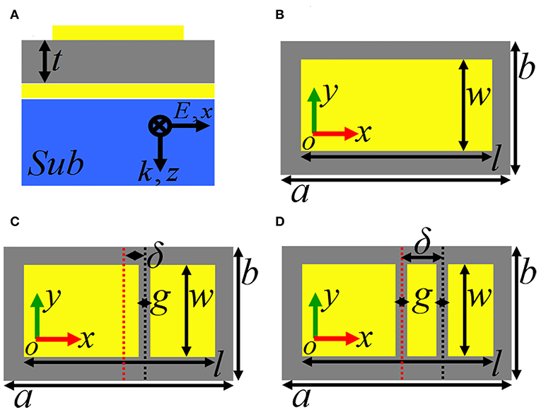
Figure 1. (A) Side view of the metamaterial absorber having the single-band, dual-band, and triple-band absorption; (B) Top view of the single-band metamaterial absorber; (C) Top view of the dual-band metamaterial absorber; (D) Top view of the triple-band metamaterial absorber.
We use commercial simulation software FDTD Solutions, which is based on the finite difference time domain method, to analyze and study the resonance performance, and near-field patterns of the designed absorption devices, including the single-band absorption, dual-band, and triple-band absorption in the following sections. During the analysis, periodic boundary conditions along the x and y directions are applied to reveal the periodic arrangement of absorption device, while the perfectly matched layers are employed in the z direction to absorb the unnecessary scattering. A plane light source with x-axis polarization propagating along the z direction radiates into the absorption device from top metallic resonator to bottom metallic board. The absorption AA is obtained from the AA = 1—TT—RR, of which the TT and RR are, respectively, the transmission and reflection of the metamaterial. Since the thickness of the bottom metallic board is greater than the skin depth of the incident beam, the TT = 0. Then the AA could be expressed by AA = 1—RR.
But the need to pay attention to is that the sizes of rectangular patch, the thickness and dielectric constant of middle insulating medium layer, the periodic dimensions of basic cell, the calculation model and its boundary conditions are unchanged in the whole manuscript unless otherwise specified. In other words, except for the introduction of air gaps into the rectangular patch, there is no other parameter changes for the dual-band and triple-band absorption in the following sections. Therefore, the advantage of this method (by introducing air gaps into the rectangular patch) in this manuscript is that the multiple-band absorption can be obtained without increasing the cell sizes horizontally and vertically, which is totally different from the previous design strategies.
Under the preset parameters and appropriate calculation model, the absorption response of the metallic rectangular patch resonator is shown in Figure 2A. Single resonance absorption peak with the frequency of 2.57 THz is obtained. To insight into the physical mechanism of the single-band absorption, near-field distributions of this absorption peak at 2.57 THz are given in Insets (I) and (II) of Figure 1A. It is observed that its electric field in Inset (II) is mostly concentrated on the edges of the rectangular resonator, and its magnetic field in Inset (I) presents strong aggregation effect in the middle insulating medium layer under the rectangular patch resonator. These near-field patterns reveal that this absorption peak is mainly caused by the localized resonance response of the rectangular patch resonator. We further observed that the magnetic-field patterns of the absorption peak have three obvious aggregation areas (or nodes), which is confirmed that this absorption peak at 2.57 THz is due to the third-order localized resonance of the rectangular patch [29, 30].
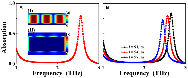
Figure 2. (A) Absorption response of the single-band metamaterial absorber, of which the insets (I) and (II) are, respectively, the electric and magnetic field patterns of the maximum absorption peak at 2.57 THz; (B) Dependence of the absorption response on the length (l) change of the rectangular patch resonator.
Because the absorption peak originates from the third-order (localized) resonance response of the rectangular patch resonator, the change in rectangular patch sizes should strongly affect the frequency of the absorption peak. As revealed in Figure 2B, the single-band absorption peak frequency exhibits blue-shift with the increase of the rectangular patch length (l). This resonance feature gives us the opportunity to design multiple-band metamaterial absorber by introducing air gaps into the rectangular patch so that the rectangular patch resonator can be divided into several separated sections with different lengths. The combined effect of the localized resonance response of each separated section should provide the possibility of realizing the multiple-band absorption. This advantage of this method is that it does not increase the structure size of the absorption device and or need to stack multiple metallic resonators, so this strategy has a lot of merits over traditional design methods of co-planar or layered, such as small size or compact structure design, ultra-thin, light weight and easy to fabricate. The following two sections will discuss in details how to use this method of introducing air gaps into the basis of the original rectangular patch resonator to design multiple-band absorption.
Design of Dual-Band Absorption
In this section, we mainly investigate and study the realization of the dual-band absorption. In the process of realization, an (or single) air gap needs to be introduced into the original rectangular patch resonator. The top-view of the dual-band absorption is demonstrated in Figure 3A or Figure 1C. The introduced air gap has the gap (g) of g = 6 μm, and width (w) of w = 44 μm. The distance between the introduced air gap and the rectangular patch center is represented by δ, here we set δ = 10 μm. Because δ is not equal to 0, the introduced air gap can split the original rectangular patch into two separated metallic sections having different lengths. As observed in Figure 3A, the length of the left separated metallic section is larger than that of the right separated metallic section. As observed in Figure 3B, two discrete resonance absorption peaks with near 100% absorbance are gained, in which the absorption peak with the lower frequency at 1.50 THz is labeled as mode A, while the absorption peak with the higher frequency at 2.25 THz is labeled as mode B. In fact, the below Figure 5B shows that the value of δ (i.e., the position of air gap into the rectangular patch) plays an important role in regulating the resonance performance of dual-band absorption.
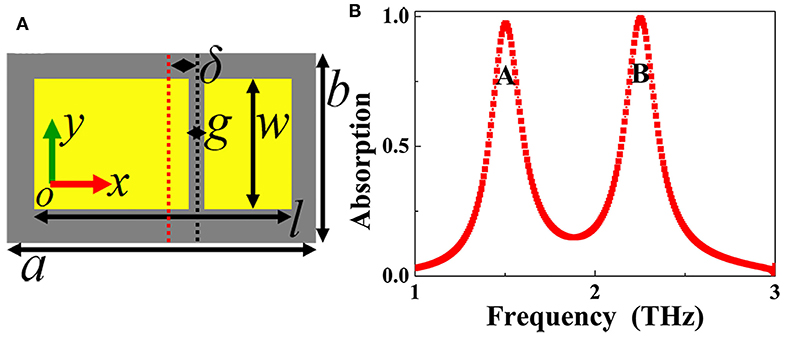
Figure 3. (A) Top view of the dual-band metamaterial absorber; (B) Absorption response of the dual-band metamaterial absorber.
In order to analyze and investigate the formation mechanism of the two absorption peaks A and B, the near-field patterns of them are given, as demonstrated in Figure 4, of which the Figures 4A,C are, respectively, the electric field patterns of the absorption peaks A and B in the center plane of the top metallic array, while the magnetic field patterns of the absorption peaks A and B in the middle insulating dielectric layer under the metallic array are presented in Figures 4B,D, respectively. We first study the physical mechanism of absorption peak A, it is found that its electric field in Figure 4A is mainly localized at both edges (or sides) of the left separated metallic section. In the meantime, its magnetic field in Figure 4C is mostly concentrated on the middle insulating dielectric layer under the left separated metallic section. The electric and magnetic field patterns of the absorption peak A indicate that the localized resonance response of the left separated metallic section is the operating mechanism of the absorption mode. We further found in Figure 4C that there is only one strong magnetic field aggregation area (or node) for absorption peak A, which shows that this absorption is caused by the first-order localized resonance response of the left separated metallic section [29, 30]. Unlike the case of the absorption peak A that its electric and magnetic fields are mainly related to the left separated metallic section, the near-field patterns of the absorption peak B are primarily associated with the right separated metallic section. In detail, the electric field of the absorption peak B in Figure 4B shows the strong enhancement effect at both sides of the right separated metallic section, and its magnetic field with one strong aggregation area (or node) is mostly distributed at the middle insulating dielectric layer under the right separated metallic section, see Figure 4D. These near-field distributions reveal that the formation of the absorption peak B is chiefly due to the first-order localized resonance response of the right separated metallic section [29, 30]. From these analyses, it can be seen that the superposition effect of the first-order localized resonance response of the two (or left and right) separated sections leads to the dual-band absorption.
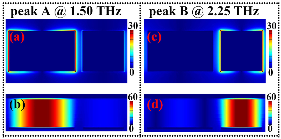
Figure 4. Panels (A,B) are respectively the electric and magnetic field patterns of the absorption peak A at 1.50 THz; (C,D) are respectively the electric and magnetic field patterns of the absorption peak B at 2.25 THz.
Because the absorption peaks A and B are associated with the left and right separated metallic sections, respectively, the size changes in the specific section will affect its corresponding resonance performance. As shown in Figure 5A, the gap (g) of the air gap into the rectangular patch play an important role in controlling the resonance frequencies of the absorption peaks A and B. The frequencies of them exhibit the similar moving trend, that is, with the increase of the gap (g), they are both gradually increasing. This is a known fact that the resonance (or absorption) frequency of the localized resonance response is inversely proportional to the metallic resonator length. The larger the metallic resonator length, the smaller the absorption frequency. As the rectangular patch length (l) remains unchanged in whole manuscript, the larger the gap (g), the smaller the separated metallic section length, corresponding to the larger absorption frequency.
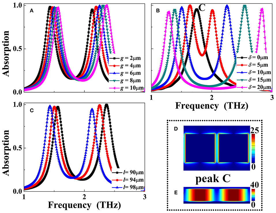
Figure 5. Dependence of the absorption response of the dual-band metamaterial absorber on the size changes of the gap (g) in (A), position (δ) in (B), and rectangular patch length (l) in (C); (D,E) are, respectively, the electric and magnetic field patterns of the absorption peak C at 1.75 THz.
The resonance frequencies of the absorption peaks A and B can also be adjusted by varying the position (δ) of the air gap into the rectangular patch as well as the length of the rectangular patch itself. As revealed in Figure 5B, the resonance frequency of the absorption peak A gradually decrease with the increase of the air gap position (δ), while the frequency of the absorption peak B is increasing gradually. With the increase of the air gap position (δ), the length of the left separated metallic section becomes larger, while the length of the right separated metallic section decreases, resulting in the opposite movement trend of their respective absorption frequencies. Obviously, when the air gap position (δ) is equal to zero, the left separated metallic section length is the same as that of the right, thus only one absorption peak should be realized. As given in the black curve of the Figure 5B, it is true that only one absorption peak labeled as mode C. According to the near-field patterns of the mode C in Figures 5D,E, the formation mechanism of this mode is mainly derived from the first-order localized resonance response of the two (or left and right) separated metallic sections with identical sizes. In addition, when the length (l) of the rectangular patch itself is increasing, it will increase the lengths of the left and right separated metallic sections at the same time, resulting in the simultaneous decrease of the absorption peaks A and B, as shown in Figure 5C.
Design of Triple-Band Absorption
The introduction of more air gaps into the rectangular patch has the ability to achieve the perfect absorption at more frequency bands. As a typical example, this section presents the realization of the triple-band metamaterial absorber using two air gaps with the identical sizes into the rectangular patch. The top-view of the triple-band absorption device is illustrated in Figure 6A (or Figure 1D). The two air gaps have the same gap (g) of g = 6 μm and width (w) of w = 44 μm. The center of the left (or first) air gap coincides with the rectangular patch center, while the distance between the right (or second) air gap and the rectangular patch center is δ = 20 μm. Because of the different positions of the two air gaps into the rectangular patch, the original rectangular patch resonator can be divided into three separated metallic sections, of which the left section has the longest length, the right section is the second, and the middle section is the smallest. As shown in the absorption spectral of Figure 6B, three distinct absorption peaks with near perfect absorbance are realized. The first absorption peak with the resonance frequency of 1.82 THz is labeled as the mode D, and the last two absorption peaks localized at the frequencies of 2.83 THz and 2.93 THz are, respectively, marked as modes E and F.
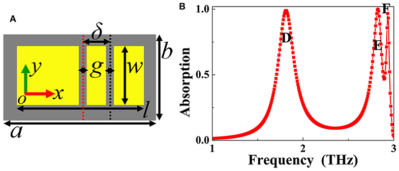
Figure 6. (A) Top view of triple-band metamaterial absorber; (B) Absorption response of the triple-band metamaterial absorber.
To insight into the physical origin of the triple-band absorption, near-field patterns of the three absorption peaks D, E, and F are presented, as given in Figure 7, of which the Figures 7A,B are, respectively, the electric and magnetic field patterns of the absorption peak D in the center plane of the top metallic array and the middle insulating dielectric layer under the top metallic array, the electric and magnetic field patterns of the absorption peak E (or F) in the center plane of the top metallic array and the middle dielectric layer under the top metallic array are, respectively, demonstrated in Figures 7C,D (or Figures 7E,F). In detail, for absorption peak D, its electric field in Figure 7A is chiefly focused on both edges (or sides) of the left separated metallic section along the electric field direction of the incident beam, and the magnetic field of the absorption peak with one strong aggregation area (or node) is mostly concentrated on the insulating dielectric layer under the left separated metallic section, see Figure 7B. These field patterns prove that the absorption peak D is resulted from the first-order localized resonance response of the left separated metallic section. Considering the distribution characteristics of the electric and magnetic fields in Figures 7C,D, the physical mechanism of the absorption peak E should be come from the first-order localized resonance response of the right separated metallic section.
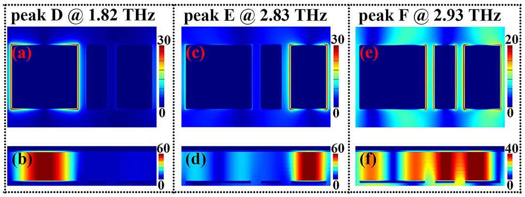
Figure 7. Panels (A,B) are respectively the electric and magnetic field patterns of the absorption peak D at 1.82 THz; (C,D) are respectively the electric and magnetic field patterns of the absorption peak E at 2.83 THz; (E,F) are respectively the electric and magnetic field patterns of the absorption peak F at 2.93 THz.
Different from the resonance mechanism of the absorption peaks D and E, the formation of the absorption peak F is not due to the localized resonance response of the single separated metallic section (or a specific separated section), but to the superposition effect of the separated metallic sections. The enhanced electric field patterns are not only distributed on both edges of the middle separated metallic section, but also on the edges of the left and right separated metallic sections, see Figure 7E. The enhanced magnetic fields also have the similar distribution characteristics that they are not only focused on the insulating dielectric layer under the middle separated metallic section, but also on the insulating dielectric layer under the left and right separated metallic sections, see Figure 7F. It should be noted that the proportion of electric field distributions in the left separated metallic section is significantly lower than that of the other separated metallic sections, and the magnetic field patterns in the insulating dielectric layer under the top separated metallic sections have also the similar features that the proportion of the magnetic fields in the left insulating dielectric layer is obviously smaller than that of the other two parts. It is revealed that the formation of the absorption peak F is mostly attributed to the hybrid effect of the first-order resonance response of the middle and right separated metallic sections.
The geometric parameters of the introduced air gaps, including the gap (g) and the position (δ), play the rather important role in controlling the performance of the triple-band absorption device. It can be seen from Figure 8A that resonance frequency of the absorption peak D is strongly affected by the position shift of the left (or first) air gap, while the last two absorption peaks E and F show the slight frequency movements. The resonance frequency of the absorption peak D can also be controlled by varying the gap (g) of the left (or first) air gap, see Figure 8B. Different from the case of the parameter changes of the left (or first) air gap that mainly regulate the resonance frequency of the absorption peak D, the size changes of the right (or second) air gap chiefly affect the absorption peaks E and F, while the frequency movement of the absorption peak D is nearly unchanged, see Figures 8C,D. These results indicate that triple-band absorption with specific resonance frequencies (or application demands) can be realized by independently adjusting the parameters of the air gap.
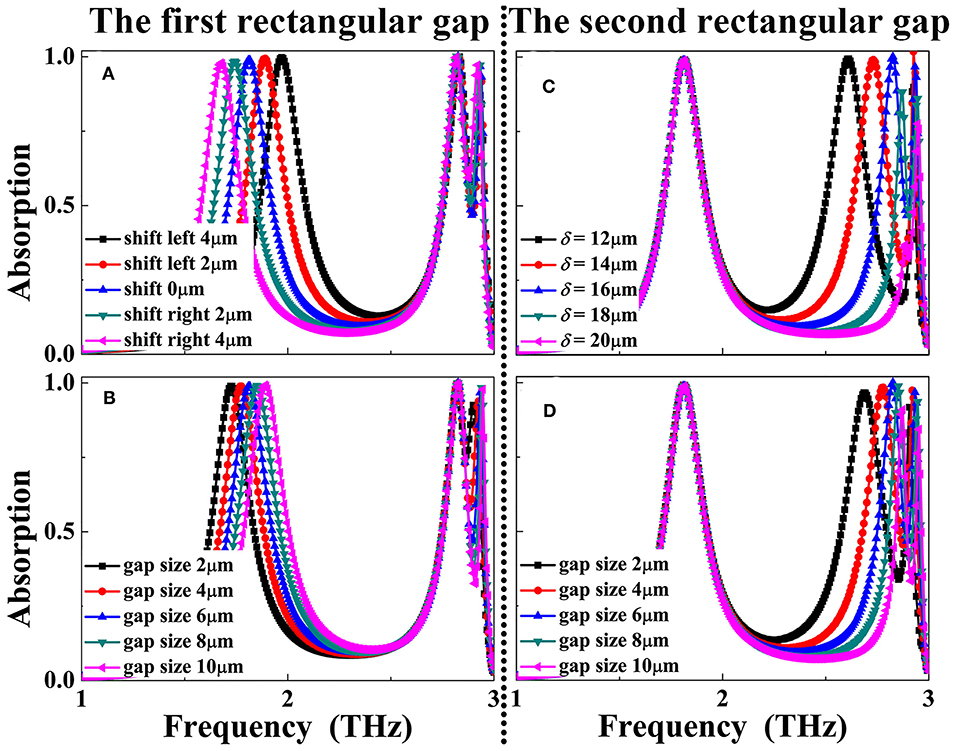
Figure 8. Dependence of the absorption response of the triple-band metamaterial absorber on the size changes of the left (or first) air gap position (δ) in (A), gap (g) in (B); Dependence of the absorption response of the triple-band metamaterial absorber on the size changes of the right (or second) air gap position (δ) in (C), gap (g) in (D).
Conclusion
In conclusion, this manuscript presents the design of multiple-band terahertz metamaterial absorber by introducing air gaps into the rectangular patch resonator. The introduction of the air gaps can split the original rectangular patch into several separated metallic sections having different lengths. The superposition effect of the first-order localized resonance response of each separated metallic section results in the multiple-band absorption. The near-field patterns of each absorption frequency point are given to investigate the physical origin of the multiple-band absorption. Results further prove that the parameters of the air gaps, including their gap and position into the rectangular patch, possess large ability in tuning the absorption frequencies of the multiple-band metamaterial absorber. The strategy proposed here, which is different from the existing one, could provide important guidance for the design of the next generation of the multiple-band metamaterial absorbers.
Data Availability Statement
The original contributions presented in the study are included in the article/supplementary material, further inquiries can be directed to the corresponding author/s.
Author Contributions
B-XW conceived the research, conducted simulations and analysis, and wrote the manuscript. YH and PL conducted simulations and analysis. NX, XW, and YW conducted analysis. JC wrote the manuscript. All authors contributed to the article and approved the submitted version.
Funding
This research was funded by National Natural Science Foundation of China (11647143), Natural Science Foundation of Jiangsu (BK20160189), China Postdoctoral Science Foundation (2019M651692), Jiangsu Postdoctoral Science Foundation (2018K113C), Fundamental Research Funds for Central Universities (JUSRP51721B), Open Fund of Key Laboratory of Optical System Advanced Manufacturing Technology, and Chinese Academy of Sciences (KLOMT190103).
Conflict of Interest
The authors declare that the research was conducted in the absence of any commercial or financial relationships that could be construed as a potential conflict of interest.
References
1. Landy NI, Sajuyigbe S, Mock JJ, Smith DR, Padilla WJ. Perfect metamaterial absorber. Phys Rev Lett. (2008) 100:207402. doi: 10.1103/PhysRevLett.100.207402
2. Watts CM, Liu X, Padilla WJ. Metamaterial electromagnetic wave absorbers. Adv Mater. (2012) 24:OP98–120. doi: 10.1002/adma.201200674
3. Cui Y, He Y, Jin Y, Ding F, Yang L, Ye Y, et al. Plasmonic and metamaterial structures as electromagnetic absorbers. Laser Photon Rev. (2014) 8:495–520. doi: 10.1002/lpor.201400026
4. Chen HT. Interference theory of metamaterial perfect absorbers. Opt Express. (2012) 20:7165–72. doi: 10.1364/OE.20.007165
5. Liu X, Starr T, Starr AF, Padilla WJ. Infrared spatial and frequency selective metamaterial with near-unity absorbance. Phys Rev Lett. (2010) 104:207403. doi: 10.1103/PhysRevLett.104.207403
6. Li Z, Butun S, Aydin K. Ultranarrow band absorbers based on surface lattice resonances in nanostructured metal surfaces. ACS Nano. (2014) 8:8242–48. doi: 10.1021/nn502617t
7. Wang BX, Wang GZ. Temperature tunable metamaterial absorber at THz frequencies. J Mater Sci. (2017) 28:8487–93. doi: 10.1007/s10854-017-6570-x
8. Hu X, Xu G, Wen L, Wang H, Zhao Y, Zhang Y, et al. Metamaterial absorber integrated microfluidic terahertz sensors. Laser Photon Rev. (2016) 10:962–9. doi: 10.1002/lpor.201600064
9. Song J, Wang L, Li M, Dong J. A dual-band metamaterial absorber with adjacent absorption peaks. J Phys D. (2018) 51:385105. doi: 10.1088/1361-6463/aad7e1
10. Yuan S, Yang R, Xu J, Wang J, Tian J. Photoexcited switchable single-/dual-band terahertz metamaterial absorber. Mater Res Express. (2019) 6:075807. doi: 10.1088/2053-1591/ab1962
11. Agarwal M, Meshram MK. Metamaterial-based dual-band microwave absorber with polarization insensitive and wide-angle performance. AIP Adv. (2018) 8:095016. doi: 10.1063/1.5020702
12. Kim J, Han K, Hahn JW. Selective dual-band metamaterial perfect absorber for infrared stealth technology. Sci Rep. (2017) 7:6740. doi: 10.1038/s41598-017-06749-0
13. Yao G, Ling F, Yue J, Luo C, Ji J, Yao J. Dual-band tunable perfect metamaterial absorber in the THz range. Opt Express. (2016) 24:1518–27. doi: 10.1364/OE.24.001518
14. Khuyen BX, Tung BS, Kim YJ, Hwang JS, Kim KW, Rhee JY, et al. Ultra-subwavelength thickness for dual/triple-band metamaterial absorber at very low frequency. Sci Rep. (2018) 8:11632. doi: 10.1038/s41598-018-29896-4
15. Mishra N, Choudhary DK, Chowdhury R, Kumari K, Chaudhary RK. An investigation on compact ultra-thin triple band polarization independent metamaterial absorber for microwave frequency applications. IEEE Access. (2017) 5:4370–6. doi: 10.1109/ACCESS.2017.2675439
16. Chaurasuya D, Ghosh S, Bhattacharyya S, Srivastava KV. An ultrathin quad-band polarization-insensitive wide-angle metamaterial absorber. Micro Opt Technol Lett. (2015) 57:697–702. doi: 10.1002/mop.28928
17. Jafari FS, Naderi M, Hatami A, Zarrabi FB. Microwave Jerusalem cross absorber by metamaterial split ring resonator load to obtain polarization independence with triple band application. AEU-Inter J Electron Commun. (2019) 101:138–44. doi: 10.1016/j.aeue.2019.02.002
18. Agarwal M, Behera AK, Meshram MK. Wide-angle quad-band polarisation-insensitive metamaterial absorber. Electron Lett. (2016) 52:340–2. doi: 10.1049/el.2015.4134
19. Singh HS. Super compact ultrathin quad-band with wide angle stability polarization independent metamaterial absorber. Micro Opt Technol Lett. (2020) 62:718–25. doi: 10.1002/mop.32054
20. Stephen L, Yogesh N, Subramanian V. Realization of bidirectional, bandwidth-enhanced metamaterial absorber for microwave applications. Sci Rep. (2019) 9:10058. doi: 10.1038/s41598-019-46464-6
21. Kalraiya S, Chaudhary RK, Gangwar RK, Abdalla AM. Compact quad-band polarization independent metamaterial absorber using circular/square metallic ring resonator. Mater Res Express. (2019) 6:055812. doi: 10.1088/2053-1591/ab0623
22. Hokmabadi MP, Wilbert DS, Kung P, Kim SM. Polarization-dependent, frequency-selective THz stereometamaterial perfect absorber. Phys Rev Appl. (2014) 1:044003. doi: 10.1103/PhysRevApplied.1.044003
23. Su Z, Yin J, Zhao X. Terahertz dual-band metamaterial absorber based on graphene/MgF2 multilayer structures. Opt Express. (2015) 23:1679–90. doi: 10.1364/OE.23.001679
24. Bhattacharyya S, Ghosh S, Chaurasiya D, Srivastava KV. Bandwidth-enhanced dual-band dual-layer polarization-independent ultra-thin metamaterial absorber. Appl Phys A. (2015) 118:207–15. doi: 10.1007/s00339-014-8908-z
25. Wang BX, Tang C, Niu Q, He Y, Chen T. Design of narrow discrete distances of dual-/triple-band terahertz metamaterial absorbers. Nanoscale Res Lett. (2019) 14:64. doi: 10.1186/s11671-019-2876-3
26. Liu S, Zhuge J, Ma S, Chen H, Bao D, He Q, et al. A bi-layered quad-band metamaterial absorber at terahertz frequencies. J Appl Phys. (2015) 118:245304. doi: 10.1063/1.4938110
27. Kajtar G, Kafesaki M, Economou EN, Soukoulis CM. Theoretical model of homogeneous metal-insulator-metal perfect multi-band absorbers for the visible spectrum. J Phys D. (2016) 49:055104. doi: 10.1088/0022-3727/49/5/055104
28. Astorino MD, Frezza F, Tedeschi N. Ultra-thin narrow-band, complementary narrow-band, and dual-band metamaterial absorbers for applications in the THz regime. J Appl Phys. (2017) 121:063103. doi: 10.1063/1.4975687
29. Dayal G, Ramakrishna SA. Multipolar localized resonances for multi-band metamaterial perfect absorbers. J Opt. (2014) 16:094016. doi: 10.1088/2040-8978/16/9/094016
Keywords: metamaterial, terahertz, perfect absorber, multiple-band absorption, rectangular patch resonator
Citation: Wang B-X, He Y, Lou P, Xu N, Wang X, Wang Y and Cao J (2020) Multiple-Band Terahertz Metamaterial Absorber Using Multiple Separated Sections of Metallic Rectangular Patch. Front. Phys. 8:308. doi: 10.3389/fphy.2020.00308
Received: 21 May 2020; Accepted: 06 July 2020;
Published: 13 August 2020.
Edited by:
Zhi Hong, China Jiliang University, ChinaReviewed by:
Guangsheng Deng, Hefei University of Technology, ChinaLiang Wu, Tianjin University, China
Copyright © 2020 Wang, He, Lou, Xu, Wang, Wang and Cao. This is an open-access article distributed under the terms of the Creative Commons Attribution License (CC BY). The use, distribution or reproduction in other forums is permitted, provided the original author(s) and the copyright owner(s) are credited and that the original publication in this journal is cited, in accordance with accepted academic practice. No use, distribution or reproduction is permitted which does not comply with these terms.
*Correspondence: Ben-Xin Wang, wangbenxin@jiangnan.edu.cn