Feasibility Analysis of Magnetorheological Absorber in Recoil Systems: Fixed and Field Artillery
 Qing Ouyang
 Hongsheng Hu1
  Jiong Wang
 Zhaochun Li
- 1College of Mechanical and Electrical Engineering, Jiaxing University, Jiaxing, China
- 2School of Mechanical Engineering, Nanjing University of Science and Technology, Nanjing, China
- 3College of Electronic and Mechanical Engineering, Nanjing Forestry University, Nanjing, China
Magnetorheological (MR) absorbers in the artillery recoil systems are usually used to dissipate the impact energy as much as possible and reduce the recoil force transmitted to the artillery carriage, while the firing stability of artillery during the buffer process is rarely considered. In this paper, we analyzed the firing stability characteristics of the fixed artillery and the field artillery systems and established corresponding mechanical models. Then, we proposed the ideal recoil F–v curves of these two kinds of artillery, respectively. The “platform effect” of recoil curve was taken as the recoil force control target of the fixed artillery, while based on the firing stability, the linear segmented recoil curve was drawn up as the ideal recoil buffer control target of the field artillery. To verify the feasibility and controllability of the designed multi-stage MR absorber in two kinds of recoil buffer system, the impact tests were conducted under different current loadings. The test results show that the designed MR absorber can realize different buffer control effects by changing the input current, but the ideal “platform effect” recoil curve of the fixed artillery cannot be completely realized due to small controllable damping force output. In the field artillery recoil system, the MR absorber can realize ideal recoil buffer control in the range of 0°–25° firing angles.
Introduction
The recoil force produced by the artillery firing can impart substantial vibrations and affect the fatigue life of the structure (Bhatnagar, 2005). Also, excessive vibrations can pose a limit on the rate of fire so that mitigating or isolating these vibrations can dictate design requirements (Mitchell et al., 2011). The traditional recoil mechanisms usually adopt passive buffering components, such as a stiff spring, a hydraulic damper (Hajihosseinloo et al., 1989), gas shock absorbers, rubber shock absorbers, or muzzle brakes (Mitchell et al., 2011; Xiao et al., 2013), which can be used independently or in combination. However, these dampers have limitations in controlling recoil performance accurately due to non-adjustability of passive elements. To be specific, they have fixed load-stroke profile, cannot handle perturbations to the recoil-rebound cycle in real time, and cannot handle changes in operating conditions arising from perturbations in the firing impulse (Harinder and Wereley, 2014).
Because the magnetorheological (MR) absorber has an adjustable output damping force, has a simple structure, is easy to control, and has a rapid response, many scholars have tried to apply it to the shock absorption applications, such as helicopter landing gears (Choi et al., 2016; Powell et al., 2016; Han et al., 2018; Saleh et al., 2019), seat suspensions (Yu et al., 2009; Sun et al., 2017; Bai and Yang, 2019), and artillery recoil systems (Zhang et al., 2019). Ahmadian’s research team is one of the pioneers in introducing the MR absorbers into the artillery recoil systems (Ahmadian and Poynor, 2001), designing the first-generation MR absorber for the weapon recoil system and carrying out field testing on the single-shot 50 caliber BMG rifle. They have conducted many researches on MR buffering control technology, including the rheological characteristics of MR fluid under high impact velocity (Goncalves et al., 2006), absorber structure design, and semi-active control algorithm (Ahmadian et al., 2005; Ahmadian and Norris, 2008). Bajkowski and Bajkowski (2012) installed the MR absorber in the 7.62-mm AKMS automatic carbine recoil system in 2012 to realize stable dissipation of the firing impact energy, so that the impact recoil force transmitted to the shoulder of the shooter was small, and the firing stability and comfort were improved at the same time. After that, they had continued to study the application of MR absorber in 12.7-mm large caliber machine artilleries (Bajkowski and Floiriańczyk, 2013; Bajkowski et al., 2014). These above researches verified the effectiveness of MR devices in recoil system by experiment studies. Meanwhile, Harinder and Wereley (2014) realized recoil soft landing through adaptive control from the perspective of recoil system controllability. Li and Wang (2012) and Li et al. (2018) designed and manufactured a full-scale artillery recoil system and carried out impact test on a firing test rig that consists of a 30-mm caliber, multi-action automatic artillery with an MR absorber mounted to the fixed base through a sliding guide. Most of the above researches have been focused on dissipating impact energy and minimizing recoil load transmissions to the artillery cradle and improving firing accuracy by installing semi-active MR absorbers as much as possible. However, these previous studies have rarely paid attention to the requirements of firing stability for buffer control.
The fixed artillery (such as naval artillery, tank artillery, etc.) is usually fixed on the ground or installed on a heavy foundation, and its firing stability is guaranteed. The recoil buffer control target of this kind of artillery is mainly to shorten the recoil length and smooth the recoil force as much as possible. However, the field artillery (such as towed artillery, mountain artillery, etc.) is usually lighter in weight and more maneuverable, and its firing stability is the primary consideration (Ouyang et al., 2016). Therefore, the MR absorber in the field artillery should first satisfy the firing stability of the limit firing angle and then consider the principle of reducing the recoil force. How to evaluate the application feasibility of the MR recoil absorber according to the recoil buffer requirements of these two kinds of artillery is the main purpose of this paper.
This paper is arranged in five sections, starting with the introduction in section “Introduction,” followed by the dynamic analysis of the recoil system in section “Dynamic Analysis of Recoil System,” which mainly analyzes the mechanical model and shooting stability during the firing process, and provides the ideal force-stroke profile for the MR absorber at different types of artillery. Section “MR Absorber and Test Rig” introduces the structure of the MR absorber and impact test rig. Section “Experimental Results and Analysis” presents an impact experiment on the novel MR absorber to establish the dynamic characteristics of the absorber in recoil system of different types of artillery and analyzes the experiment results. The conclusions are in section “Performance Evaluation.”
Dynamic Analysis of Recoil System
Stability Analysis
The artillery recoil system can be regarded as a single degree of freedom system during the firing process, as shown in Figure 1. It should be noted that we ignore the spring component and only use the MR absorber as the main buffer component in the recoil system. The active force (i.e., recoil force, gravity component of recoil mass), constraint reaction (i.e., friction), and recoil damping force (i.e., MR damping force) form a complicated force system. Taking the horizontal and the vertical direction is the x and y axis, respectively, and using D’Alembert’s principle, the force and moment balance equation of the recoil system are as follows (Li and Wang, 2012; Ouyang et al., 2016):

Figure 1. Structural diagram of recoil system.
where FR is the damping force generated by the MR recoil absorber to dissipate the impact load Fpt, which results from the explosion of the gunpowder, g is the acceleration of gravity, and φ is the firing angle of artillery. FT, FNA, and FNB are the horizontal reaction force provided by the ground at the fulcrum B of the parking hoe, and the vertical reaction force of the ground on the wheel and the parking hoe, respectively, while h is the distance from the bore axis to fulcrum B and Lk is the distance from the centroid of the recoil moving part to the bore axis. Lφ is the horizontal distance from the center of gravity of the whole artillery to the fulcrum B in the recoil process when the firing angle is φ. LAB is the horizontal distance between fulcrums A and B. mz is the overall mass of artillery.
According to the Eq. (1), the three constraint reaction forces FT, FNA, and FNB can be solved, respectively. The stability of artillery means that the artillery does not jump off the ground during firing, that is, FNA ≥ 0, as described by the following equation:
Thus,
The left term of inequality (3) is the moment that makes the artillery press to the ground, which is called the stable moment. Meanwhile, the two items on the right side tend to tip the artillery over about fulcrum B, which is called overturning moment. When the internal ballistic parameters, and the structural dimensions of recoil system are determined, the artillery’s stability is only related to the damping force FR. How to reduce the FR as much as possible is the primary factor to be considered to reduce the overturning moment and to enhance artillery’s stability, especially for field artillery, which requires more stringent firing stability.
To obtain the ideal recoil force curve of field artillery, we should analyze the artillery stability condition during recoil movement, since the moving mass moves backward during high speed and will provide additional overturning moments. The shooting stability condition considering the recoil movement process can be expressed as:
here, L0ϕ is the horizontal distance from the center of mass of the whole artillery to fulcrum B before firing when the firing angle is ϕ.
It can be seen from Eq. (4) that with the increase of recoil stroke x, the stability moment will decrease accordingly, thus reducing the stability of the artillery. Another variable in Eq. (4) is the moment arm h that related to the firing angle ϕ. The larger the firing angle is, the smaller the moment arm h is, which leads to the reduction of the overturning moment term FRh, thus enhancing the stability of the artillery. Therefore, there is a minimum firing angle ϕ j* that can maintain the stability of the artillery, and the ultimate recoil damping force FRj* that makes the artillery stability is:
Here, the footmark j* of parameter values represents firing angle ϕ = ϕj*.
Considering the safety margin, introducing the safety factor λ(λ = 0.9) and ignoring the instantaneous impact force Fpt caused by gunpowder combustion. The recoil damping force condition to stabilize artillery firing is as follows:
Optimization Objective of Recoil Buffer Control
For fixed artilleries, due to the limitation of turret size and firing rate, we should give priority to reducing recoil stroke, and then minimizing the impact force transmitted to the artillery carriage as much as possible. As for the field artillery, the key is to ensure the firing stability.
Fixed Artillery Recoil
The recoil optimization control of the fixed artillery is usually evaluated by two functional indexes and it can be expressed as follows:
where x(t) and are the recoil impact velocity and acceleration, respectively.
Assuming that the recoil displacement is a constraint condition, the ideal recoil damping force should be to stably dissipate the impact force generated by gunpowder combustion in the whole recoil stroke. At this time, the ideal recoil force presents a “platform effect” and makes full use of the whole recoil stroke for buffering. However, due to the fluid inertia, fluid chamber compressibility caused by MR fluid–air mixture state and the response lag factors of the recoil system in the actual application, the change of recoil damping force cannot cause a sudden jump at the moment and maintain a constant value throughout the recoil stroke. Therefore, a modified recoil curve is proposed, as shown in Figure 2. That is, the recoil force increases approximately linearly from FR0 to a certain constant value FRi in the initial stage and remains as constant as possible in the subsequent recoil stroke.
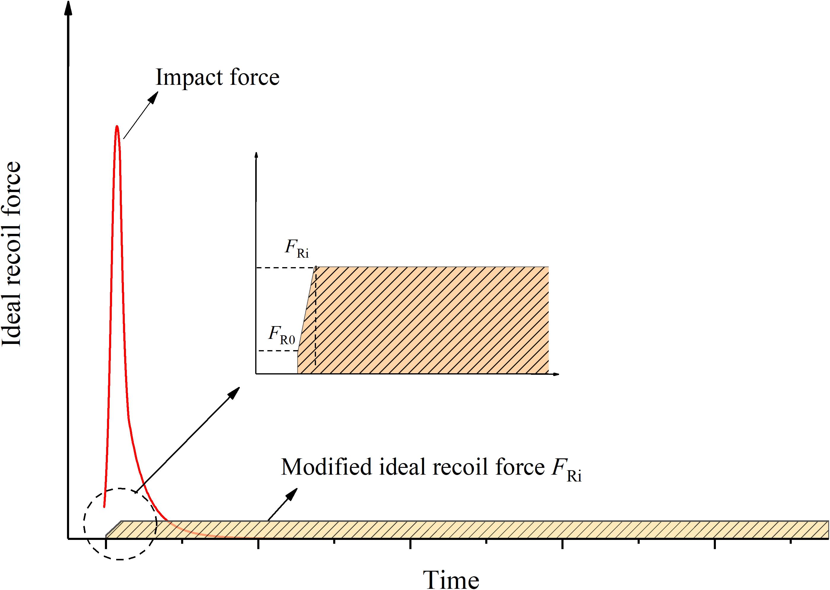
Figure 2. Modified recoil force in actual recoil process.
The output total damping force of the MR absorber Ftotal under the impact loading mainly includes the following five parts: (1) the viscous damping force, Fη; (2) the additional pressure loss caused by rapid contraction or expansion of fluid, Floss; (3) the fluid inertia force, Fi; (4) the friction force of MR absorber, Ff; and (5) the coulomb damping force generated by magnetic field, Fτ. Among them, Fη, Floss, Fi, and Ff are combined into zero-field damping force Fn, independent of magnetic field.
The viscous damping force Fη gradually decreases as the recoil speed decreases with the recoil movement. In order to ensure the ideal smoothness of the recoil process, that is, to realize the “platform effect” of the recoil damping force, the coulomb damping force Fτ should be gradually increased to make up for the decrease of viscous damping force Fη and maintain the stability of the total output damping force. Therefore, the zero-field damping force Fn and coulomb damping force Fτ of the MR absorber should satisfy the constraints:
where FRi is the ideal recoil damping force for fixed artillery.
The ideal recoil damping force FRi can be calculated from the maximum recoil displacement xmax and the maximum recoil velocity vmax:
Field Artillery Recoil
The firing process of artillery can be divided into three stages: in-chamber movement period, aftereffect period, and inertia period of projectile. Combined with the stable condition of artillery firing equation [Eq. (6)], the recoil damping rule of field artillery can be expressed in stages, as shown in Figure 3.
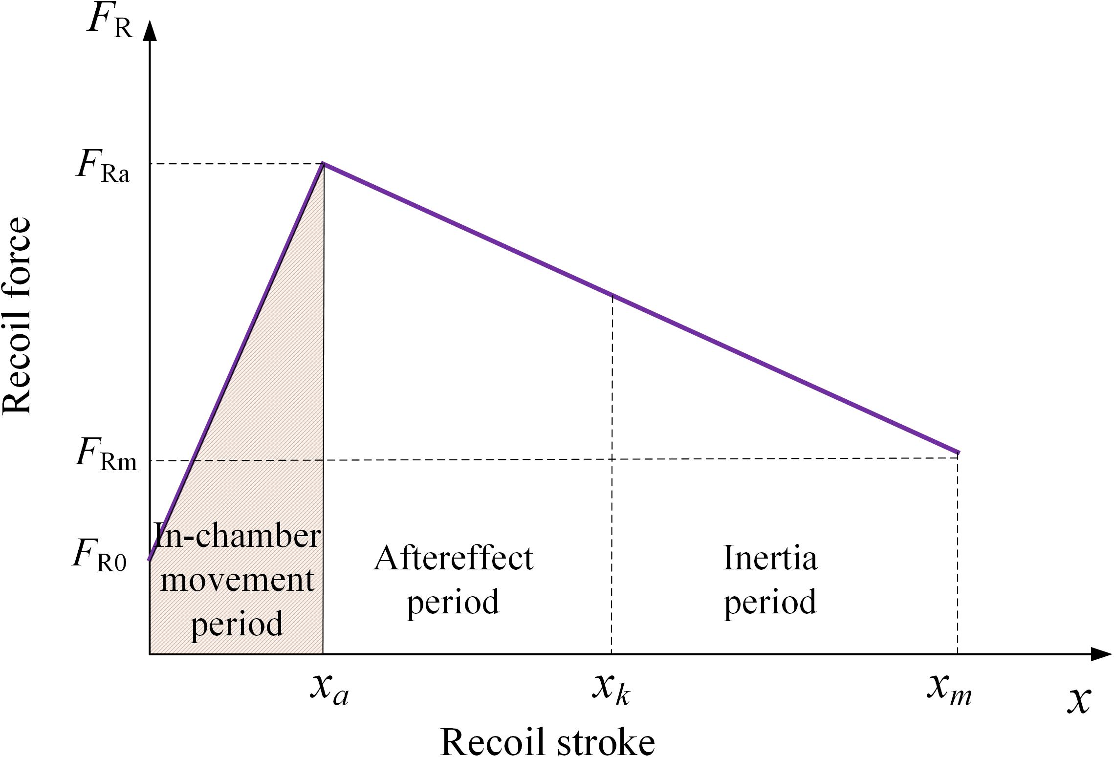
Figure 3. Schematic diagram of ideal recoil force for field artillery.
In-chamber movement period (0 < t ≤ ta):
Aftereffect period (ta < t ≤ tk):
Inertia period (tk < t ≤ tm): the recoil damping force is a function of recoil stroke x and limit firing angle ϕj*.
where FRa and xa are, respectively, the damping force and the recoil stroke at the end time ta of the in-chamber movement period; FRk and xk are the damping force and recoil stroke at the end time tk of the aftereffect period, respectively. tm is the end point of the recoil period.
In view of the limited maximum damping force that can be achieved by the existing impact bench of our research group, this paper will make a theoretical analysis of recoil damping force for a scaled model of a field artillery and discuss its damping rule under different firing angles (0–60°), as shown in Figure 4. When the recoil stroke is about 0.16 m (xa = 0.16 m), the impact speed is the maximum, and the damping force provided by the MR absorber also reaches the maximum. The maximum stroke of impact test bench is 0.6 m at the end of recoil stroke xm. Based on the consideration of artillery stability, the larger the limit firing angle is, the allowable maximum recoil damping force of the artillery can also be increased correspondingly.
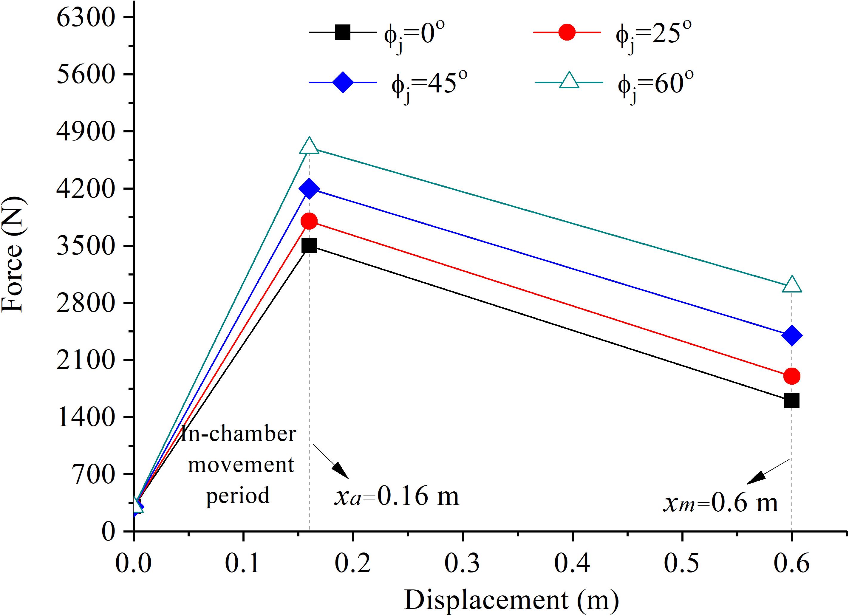
Figure 4. Ideal recoil force-stroke profile at various limiting firing angles.
MR Absorber and Test Rig
The MR absorber was designed with four-stage parallel connected coils, and its maximum stroke is more than 600 mm. Specific structural parameters of the MR absorber are detailed in references (Zheng et al., 2014, 2015) and the physical picture see in Figure 5.
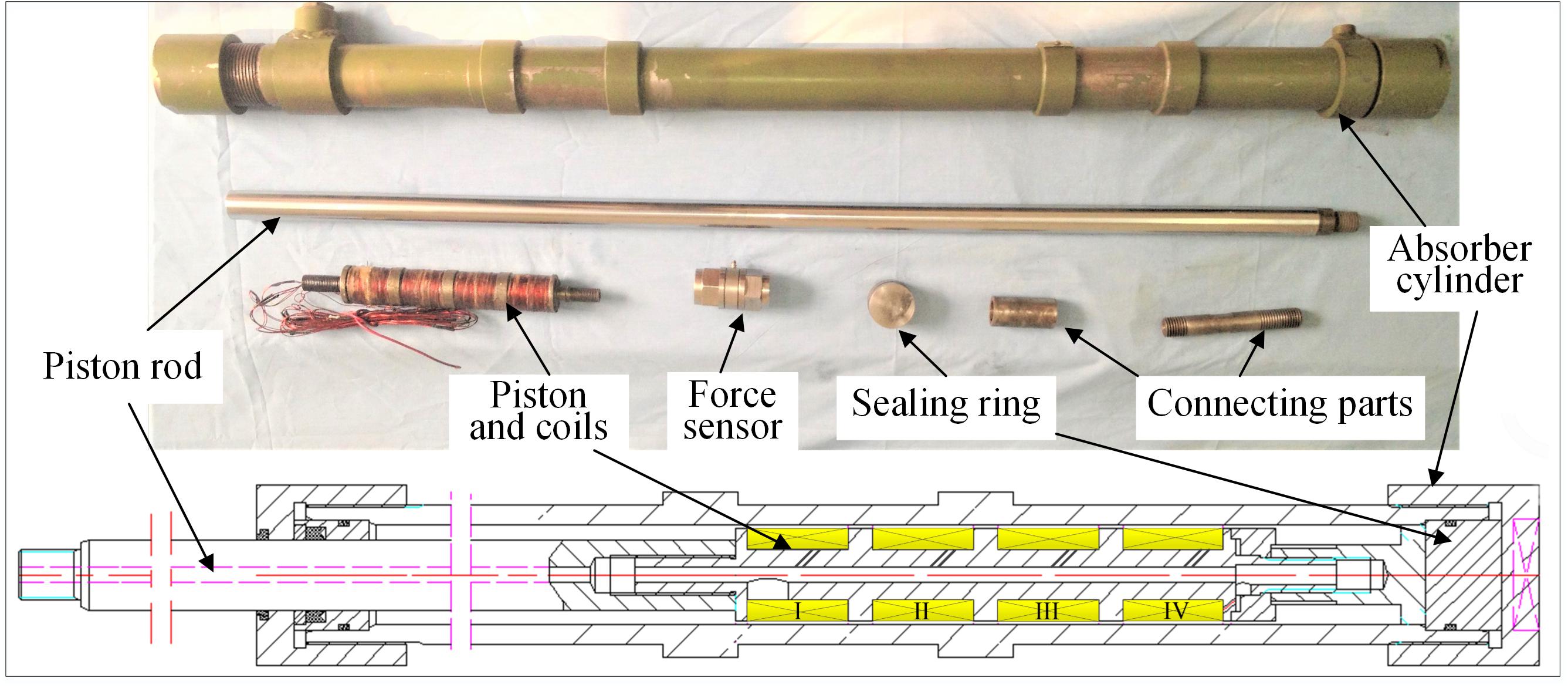
Figure 5. Physical picture of designed MR absorber.
The impact test system consists of an industrial control computer, a dSPACE system for collecting data, an impact test bench, a power supply, and various sensing devices, as shown in Figure 6. The damping force of the MR absorber was measured by a force sensor installed at the front end of the piston rod of the absorber and fixed connected with the base, while the speed and displacement data were collected by a speed/displacement sensor installed at the bottom of the bench motion guide rail.
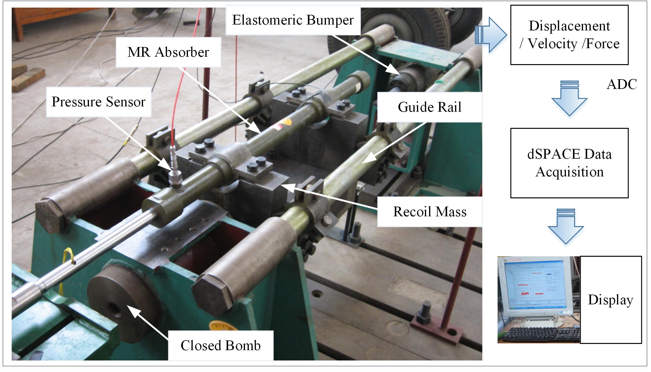
Figure 6. Impact test rig.
The instantaneous pressure generated by the combustion of gunpowder in the closed chamber was used as the test impact source to push the MR absorber to move along the smooth guide rail. Since the different firing angles of artillery do not have much influence on the performance analysis of the MR absorber, the additional recoil resistance caused by the component of gravity in the recoil motion direction can be considered together with the friction term of the recoil system, so only the horizontal impact test was conducted here.
The maximum recoil displacement of the test bench is 600 mm, and the total mass of the moving mass block and the MR absorber is 270 kg. To ensure the same impact energy of each group of test schemes, the amount of gunpowder used in the test is 6 g. However, due to the influence of factors such as the structure of the closed chamber and the combustion environment (such as temperature and humidity), the impact force produced is not completely consistent. When processing the test results, we try to choose the test data with the same maximum impact velocity; here, 3.5 m/s was selected as the impact test condition, to ensure the same initial impact energy.
Experimental Results and Analysis
Recoil Buffer Performance of Fixed Artillery
According to Eq. (10), the ideal recoil damping force of the MR absorber at the maximum impact speed of 3.5 m/s is 2838 N. The comparison of the zero-field damping force Fn when no current is applied and the ideal recoil damping force FRi of the MR absorber is shown in Figure 7. The red area in Figure 7 is the maximum coulomb damping force Fτ that can be achieved by designed MR absorber, up to 1086 N at most, while the shaded area is the coulomb force F*τ required to realize the recoil “platform effect.” This means that the coulomb damping force Fτ is too small to achieve the soft buffer control, and the MR absorber cannot completely consume the recoil impact energy without rebound in a given recoil stroke. The constraint conditions in Eq. (9) are not satisfied.
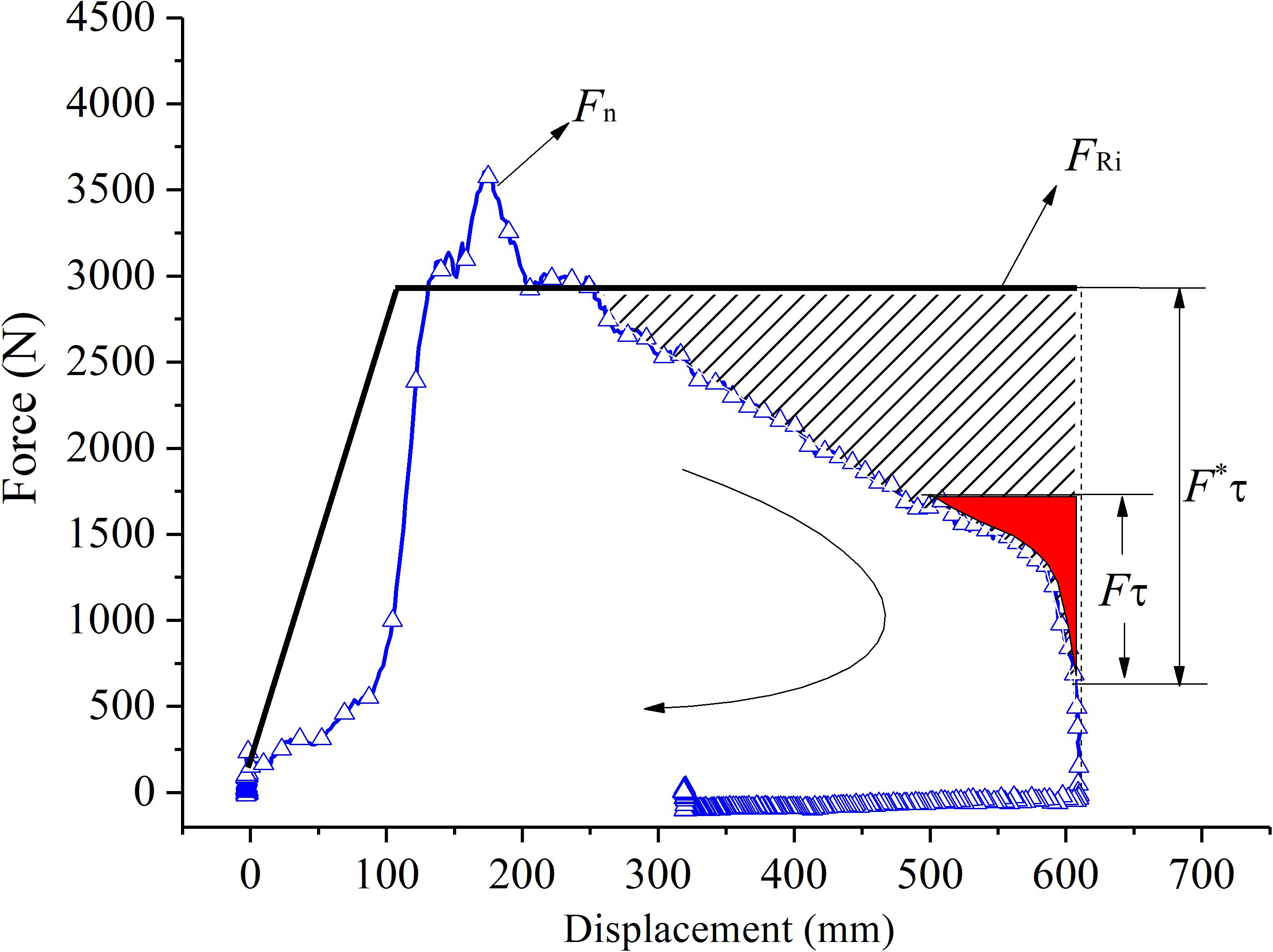
Figure 7. Comparison of actual and ideal “platform effect” recoil curves.
The above analysis shows that the designed MR absorber cannot achieve soft buffer control at the maximum impact velocity of 3.5 m/s, so under what impact conditions can this be achieved? According to the constraint Eqs (9) and (10), the impact velocity allowed to realize recoil soft buffer control can be calculated.
The average frictional force Ff of the MR absorber is about 300 N (Ouyang et al., 2016), and the throttling damping force Floss and the fluid inertia force Fi at high speed is not considered for the sake of simplicity. The output damping force of the MR absorber has a linear relation with the velocity in the stable buffering stage, as shown in Figure 8. The slope of each curve presents the viscous damping coefficient c of the MR absorber, which can be calculated as c = 914. Therefore, the constraint conditions for realizing ideal recoil can be expressed as follows:
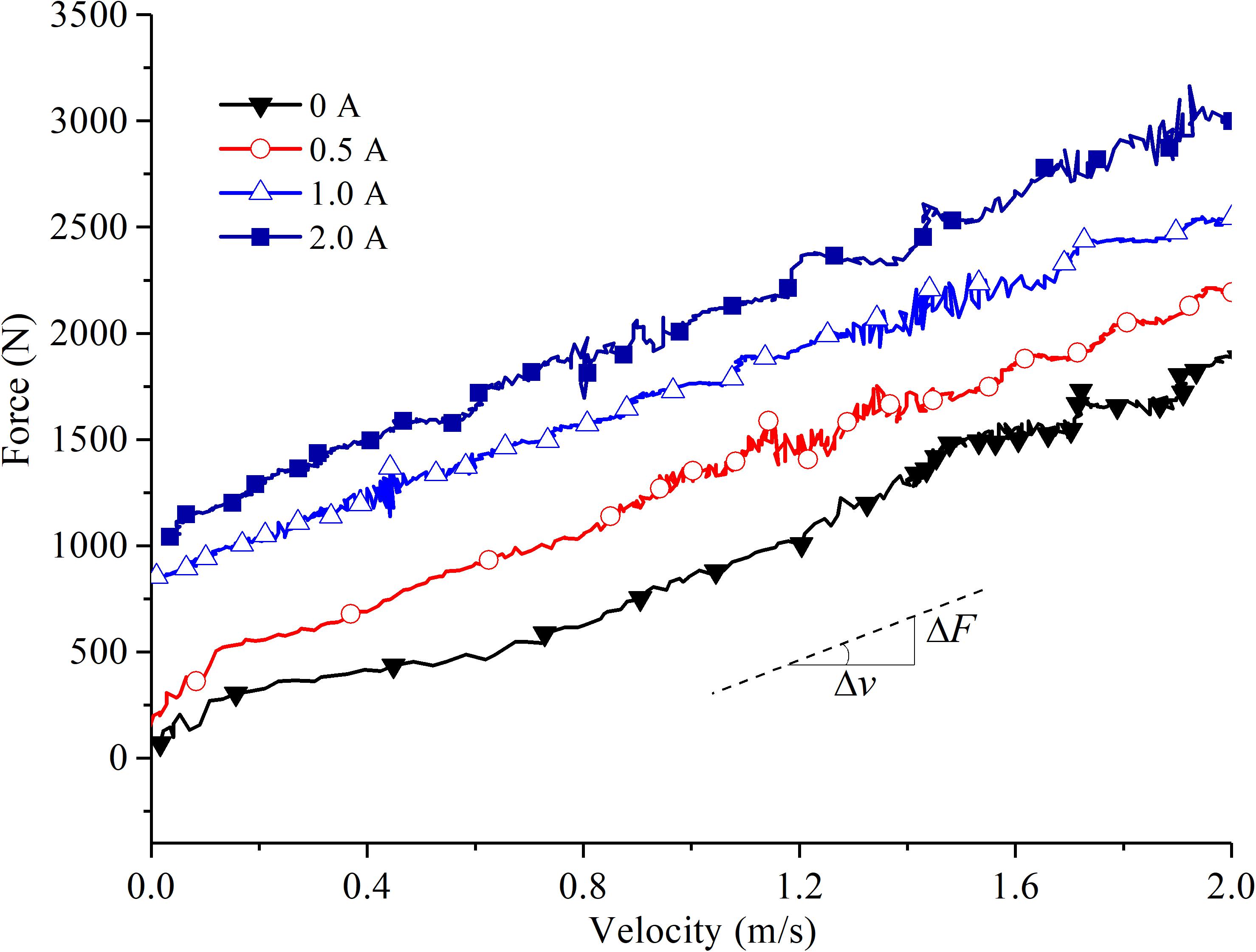
Figure 8. Relationship between recoil force and velocity in stable impact stage.
Inequality (14) is solved as follows:
As can be seen from Eq. (15), it is impossible to find a reasonable recoil velocity vi to satisfy the constraint conditions required for ideal recoil at the same time. This indicates that the designed MR absorber cannot realize the ideal recoil “platform effect” or soft buffer control at all.
Although the designed MR absorber cannot realize constant recoil force output in the whole recoil stroke, under the condition that the impact speed is less than 2.16 m/s, it can output the ideal recoil force by controlling the input current after passing the force peak value. For example, when the maximum impact speed is 2 m/s and the input current is 1 A, the recoil force variation curve of the MR absorber is shown in Figure 9, which presents recoil “platform effect” in most movement strokes.
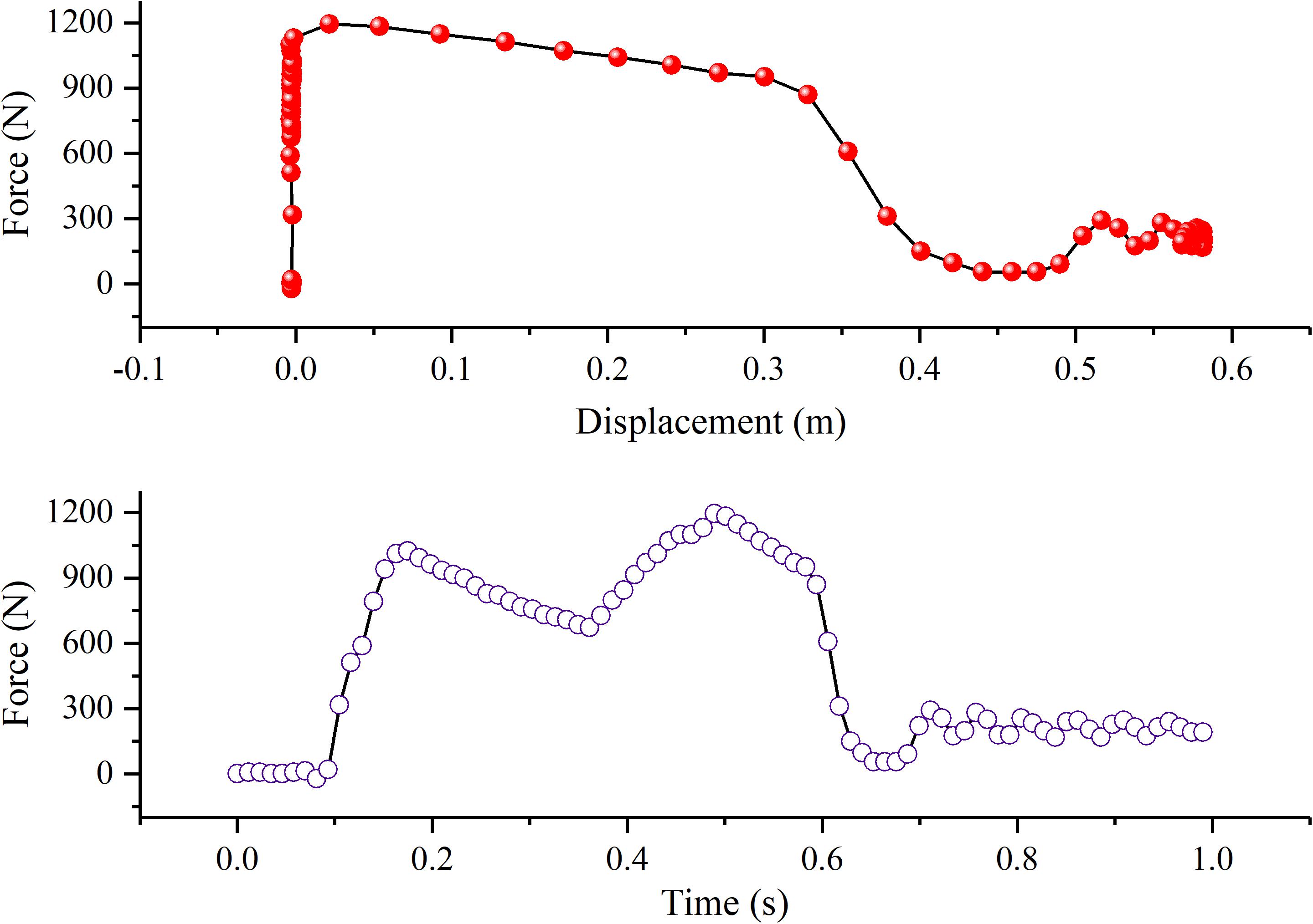
Figure 9. “Platform-like effect” by the force peak shifting control (vmax = 2 m/s).
Recoil Buffer Performance of Field Artillery
Figure 10 is a comparison diagram between the test and theoretical recoil curve of field artillery under different limiting firing angles. In the initial stage of recoil movement, the test F–v curve has strong non-linear characteristics and is not controllable. The non-linear change of the F–v curve is probably caused by an amount of compressible air mixed in the MR fluid. After the MR absorber moves for a certain distance, the MR fluid starts to be squeezed into the damping channel and make the damping force rise rapidly to the peak value, and then the MR absorber enters a damping force controllable interval. It should be pointed out that MR absorbers often show some uncontrollable behavior at the initial stage of impact, especially under high-strength or high-speed impact loads (Ahmadian and Norris, 2008; Zheng et al., 2015). This is not necessarily entirely related to the mixed air in the fluid chamber, but also to the inherent hysteresis characteristic of the MR system (Yu et al., 2017; Bai and Chen, 2019). How to solve the real-time control of the MR absorber under impact load is a problem to be solved.
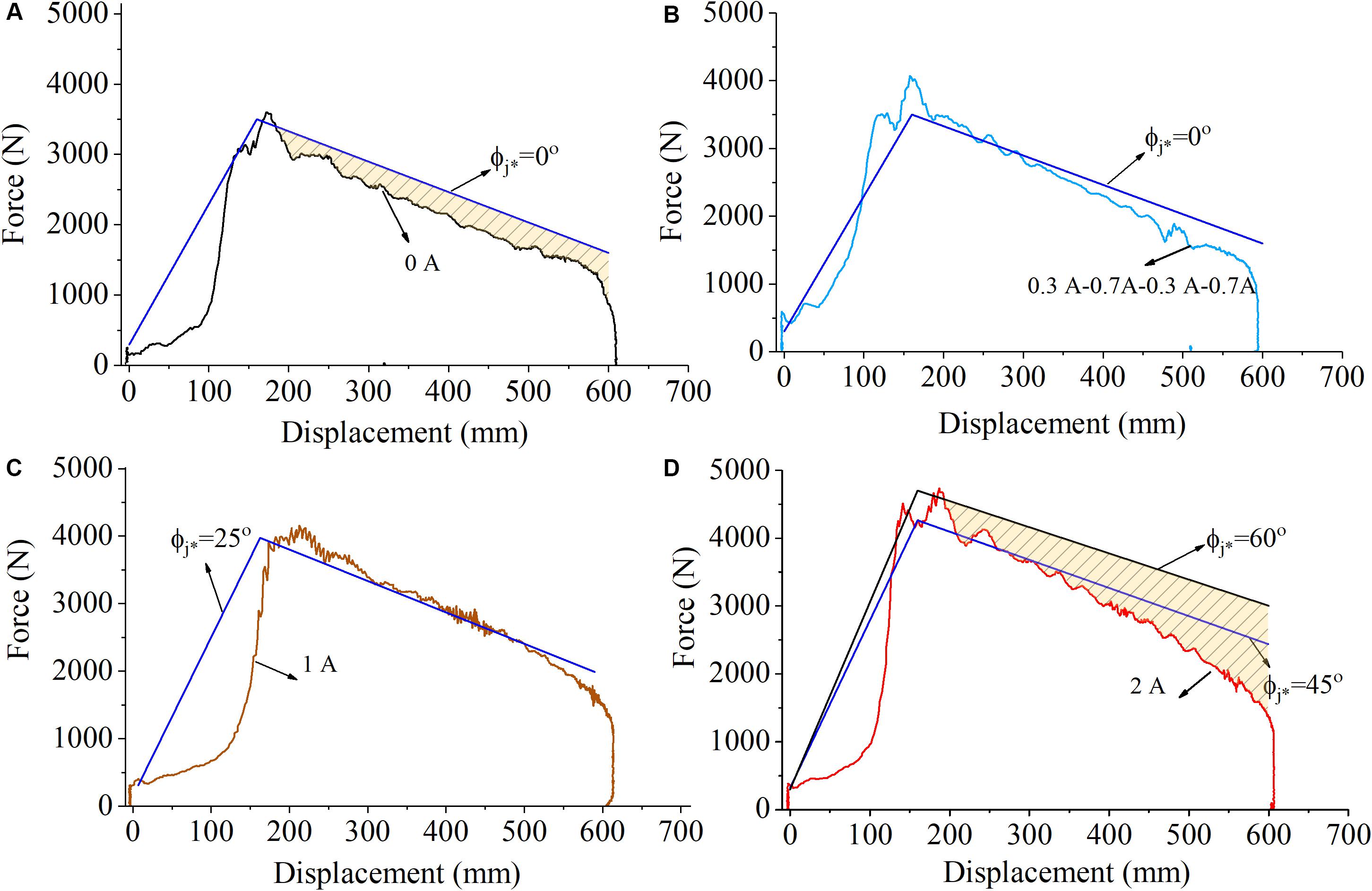
Figure 10. Comparison of measured and theoretical F-S curve of field gun. (A) I = 0A, (B) I = 0.3 A-0.7 A-0.3 A-0.7 A, (C) I = 1 A, and (D) I = 2 A.
As can be seen from Figure 10A, when no current is loaded, the recoil curve of the MR absorber is below the ideal recoil curve when the limit firing angle ϕj* = 0°, which means that although the MR absorber can guarantee the stability of the artillery during firing, it fails to give full play to the potential of dissipating impact energy (see filled area in Figure 10A). In the case of the four-stage coils, respectively, loaded with current Coil I = 0.3 A, Coil II = 0.7 A, Coil III = 0.3 A, and Coil IV = 0.7 A, the obtained F–v curve is closer to the ideal recoil curve when the limit angle ϕj* = 0°, as shown in Figure 10B.
With the current increases, a larger recoil damping force can be correspondingly provided to meet the recoil buffer control of the field artillery with a larger limit firing angle. In Figures 10C,D, when the current is 1 and 2 A, the recoil damping force is relatively matched with the ideal recoil curve corresponding to the limiting angle of 25 and 45°, respectively. This shows that, for a specific field artillery, the optimized recoil buffer control with different limit firing angles (0–25°) can be realized through the intelligent adjustable damping characteristic of the MR absorber. However, when the limit firing angle exceeds 45°, although the impact energy can still be consumed through the MR absorber and the stability of the artillery can be ensured, the deviation from the ideal recoil curve is large and the optimal recoil buffering effect cannot be realized, as shown in the filled area of Figure 10D.
Performance Evaluation
Comparison of Recoil Buffer Performances
By analyzing the application of the MR absorber in the recoil system of field artillery, it can be seen that compared with the “platform effect” of recoil curve of fixed artillery, the MR absorber is relatively “easier” to realize the ideal recoil curve of field artillery. This is because the ideal recoil curve of field artillery based on firing stability shows a piecewise rule of linear rise-linear decline, which is more consistent with the change trend of the F–v curve of MR absorber under high impact load. Specifically, the damping force of the MR absorber will rapidly climb to the peak value after withstanding the instantaneous impact force, which corresponds to the rising phase of the ideal recoil curve of the field artillery. After that, it entered a controllable second stage, and the damping force gradually dropped from the overload peak point, which corresponded to the descending stage of the recoil curve of field artillery.
As for the fixed artillery, its ideal recoil force is a constant value, and the MR absorber is difficult to overcome the problem of sharp increase and overload of damping force in the initial stage of impact.
It is should be noted that this paper only considers the application feasibility of the MR absorber in an artillery recoil system and ignores the common recoil spring and other buffer components in a real artillery recoil system. If spring elements are introduced into the MR recoil system, it can absorb part of the impact energy in the recoil process and reduce the impact force directly acting on the MR absorber, which is also beneficial to maintain the recoil “platform effect.”
Controllability Evaluation of MR Absorber
The designed MR absorber is not ideal for the application in recoil system of fixed artillery and the field artillery with limited firing angles of 45 and 60°. The main reason is that the uncontrollable damping force of the absorber is too large, which results in the controllable coulomb damping force of the absorber accounting for too low a proportion in the recoil process. The controllable coefficient ψ of MR absorber is defined as the ratio of coulomb damping force Fτ to uncontrolled zero-field damping force Fn. The larger the controllable coefficient ψ is, the better the controllable performance of the MR absorber is.
The controllable coefficient ψ = 0.31 < 1 can be obtained from Eq. (15), and there is a certain gap between the controllable coefficient range 2–6 of the general MR absorber (Nguyen and Choi, 2008; Wang et al., 2019; Zhao et al., 2020). The controllability of the absorber under impact load needs to be further improved through structural optimization design. The structure of the MR absorber needs to be further optimized to improve its controllability under impact load.
Conclusion
Based on the analysis of the impact dynamic characteristics of the MR absorber in the recoil system, the overall controllability of the absorber in the recoil system of fixed artillery and field artillery is analyzed, respectively, and the following conclusions are drawn:
(1) The ideal recoil curve of fixed artillery presents a “platform effect,” which can optimally dissipate impact energy. The test results show that the controllable coulomb damping force of the designed MR absorber accounts for a low proportion of the total output damping force, and the controllable coefficient is only 0.31, which is far smaller than the coefficient range of 2–6 of the common MR absorber, and fail to satisfy the precondition required for ideal recoil.
(2) Taking firing stability as recoil control objective of field artillery, its ideal recoil curve shows a linearly piecewise rule, which is more consistent with the change trend of the F–v curve of MR absorber under high impact load. The recoil curve of field artillery can be optimized under different limit firing angles (0–25°) through the intelligent adjustable damping characteristic of MR absorber. However, when the limit firing angle exceeds 45°, the impact energy can still be consumed by the MR absorber; at the same time, the stability of the field artillery can be ensured, failing to realize the ideal recoil rule.
(3) The designed MR absorber cannot well meet the application of artillery recoil buffer, which is mainly reflected in the low controllability and the structural defects of the single rod absorber without compensation fluid chamber, making it easy to cause fluctuation of recoil force under high-speed impact. Therefore, it is necessary to further optimize the structure design of the MR absorber. At the same time, some buffer elements such as springs can be considered to form a composite MR recoil buffer system to improve the overall performance of buffer control.
Data Availability Statement
The raw data supporting the conclusions of this article will be made available by the authors, without undue reservation.
Author Contributions
QO analyzed the firing stability characteristics of recoil systems, conducted the experiments, and analyzed the experimental data. HH processed and analyzed the experimental data. WZ established the mechanical models of recoil systems and proposed the ideal recoil curves of two kinds of artillery. JW designed the MR absorber and built the impact test rig. ZL proposed the optimization targets of buffer control in the recoil system. All authors contributed to the article and approved the submitted version.
Funding
This work was supported by the National Natural Science Foundation of China (NSFC) grant funded by the Chinese Government (Nos. 51805209 and 51675280) and in part by the Zhejiang Provincial Natural Science Foundation of China (Grant Nos. LGG20E050022 and LGG19E050017).
Conflict of Interest
The authors declare that the research was conducted in the absence of any commercial or financial relationships that could be construed as a potential conflict of interest.
References
Ahmadian, M., Goncalves, F. D., and Sandu, C. (2005). An experimental analysis of suitability of various semiactive control methods for magneto-rheological vehicle suspensions. Proc. SPIE Int. Soc. Opt. Eng. doi: 10.1117/12.599875
Ahmadian, M., and Norris, J. A. (2008). Experimental analysis of magnetorheological dampers when subjected to impact and shock loading. Commun. Nonlinear Sci. Numer. Simul. 13, 1978–1985. doi: 10.1016/j.cnsns.2007.03.028
Ahmadian, M., and Poynor, J. C. (2001). An evaluation of magneto rheological dampers for controlling gun recoil dynamics. Shock Vib. 8, 147–155. doi: 10.1155/2001/674830
Bai, X. X., and Chen, P. (2019). On the hysteresis mechanism of magnetorheological fluids. Front. Mater. 6:36. doi: 10.3389/fmats.2019.00036
Bai, X. X., and Yang, S. (2019). Hybrid controller of magnetorheological semi-active seat suspension system for both shock and vibration mitigation. J. Intell. Mater. Syst. Struct. 30, 1613–1628. doi: 10.1177/1045389x19844009
Bajkowski, M., and Bajkowski, J. M. (2012). Design of the magnetorheological damper for the recoil damping of the special object 7.62 mm caliber. Mach. Dyn. Res. 36, 15–23.
Bajkowski, M., and Floiriańczyk, A. (2013). Analysis of effect of pulse generated by the special object 12.7mm equipped in magnetorheological damping system on the thoracic spine. Mach. Dyn. Res. 37, 5–14.
Bajkowski, M., Makuch, A., and Lindemann, Z. (2014). Determining parameters of recoil reduction system with spring and magnetorheological damper intended for special object. Mach. Dyn. Res. 38, 87–96.
Bhatnagar, R. M. (2005). Recoil motion theorem. Proc. Inst. of Mech. Eng. Part K J. Multibody Dyn. 219, 173–176. doi: 10.1243/146441905x10032
Choi, Y. T., Robinson, R., Hu, W., Wereley, N. M., Birchette, T. S., Bolukbasi, A. O., et al. (2016). Analysis and control of a magnetorheological landing gear system for a helicopter. J. Am. Helicopter Soc. 61, 1–8. doi: 10.4050/jahs.61.032006
Goncalves, F. D., Ahmadian, M., and Carlson, J. D. (2006). Investigating the magnetorheological effect at high flow velocities. Smart Mater. Struct. 15, 75–85. doi: 10.1088/0964-1726/15/1/036
Hajihosseinloo, M. A., Hooke, C. J., and Walton, D. (1989). Gun recoil system performance measurement and prediction. Proc. Inst. Mech. Eng. Part C J. Mech. Eng. Sci. 203, 85–92. doi: 10.1243/pime_proc_1989_203_091_02
Han, C., Kim, B. G., and Choi, S. B. (2018). Design of a new magnetorheological damper based on passive oleo-pneumatic landing gear. J. Aircr. 55, 2510–2520. doi: 10.2514/1.c034996
Harinder, J. S., and Wereley, N. M. (2014). Optimal control of gun recoil in direct fire using magnetorheological absorbers. Smart Mater. Struct. 23:055009. doi: 10.1088/0964-1726/23/5/055009
Li, Z. C., Gong, Y., and Wang, J. (2018). Optimal control with fuzzy compensation for a magnetorheological fluid damper employed in a gun recoil system. J. Intell. Mater. Syst. Struct. 30, 677–688. doi: 10.1177/1045389x17754258
Li, Z. C., and Wang, J. (2012). A artillery recoil system employing a magnetorheological fluid damper. Smart Mater. Struct. 21:105003. doi: 10.1088/0964-1726/21/10/105003
Mitchell, M. R., Link, R. E., Wu, Y. C., Chang, H., and Tsung, T. T. (2011). Dynamic characteristics of a recoil system when firing projectiles with mach 4.4 muzzle velocity from a 105 mm cannon. J. Test. Eval. 39:103062. doi: 10.1520/jte103062
Nguyen, Q. H., and Choi, S. B. (2008). Optimal design of a vehicle magnetorheological damper considering the damping force and dynamic range. Smart Mater. Struct. 18:015013. doi: 10.1088/0964-1726/18/1/015013
Ouyang, Q., Zheng, J. J., Li, Z. C., Hu, M., and Wang, J. (2016). Controllability analysis and testing of a novel magnetorheological absorber for field gun recoil mitigation. Smart Mater. Struct. 25:115041. doi: 10.1088/0964-1726/25/11/115041
Powell, L. A. A., Choi, Y. T., Hu, W., and Wereley, N. M. (2016). Nonlinear modeling of adaptive magnetorheological landing gear dampers under impact conditions. Smart Mater. Struct. 25:115011. doi: 10.1088/0964-1726/25/11/115011
Saleh, M., Sedaghati, R., and Bhat, R. (2019). Design optimization of a bi-fold MR energy absorber subjected to impact loading for skid landing gear applications. Smart Mater. Struct. 28:035031. doi: 10.1088/1361-665x/aadb33
Sun, S. S., Ning, D. H., Yang, J., Du, H., Zhang, S. W., Li, W. H., et al. (2017). Development of an MR seat suspension with self-powered generation capability. Smart Mater. Struct. 26:085025. doi: 10.1088/1361-665x/aa76b6
Wang, M. K., Chen, Z. B., and Wereley, N. M. (2019). Magnetorheological damper design to improve vibration mitigation under a volume constraint. Smart Mater. Struct. 28:114003. doi: 10.1088/1361-665x/ab4704
Xiao, J. B., Yang, G. L., Zhao, Y., and Qiu, M. (2013). Research on dynamics of high-efficiency recoil-reducing for muzzle brake of chain gun. Adv. Mater. Res. 71, 1468–1472. doi: 10.4028/www.scientific.net/amr.712-715.1468
Yu, J. Q., Dong, X. M., and Zhang, Z. L. (2017). A novel model of magnetorheological damper with hysteresis division. Smart Mater. Struct. 26:105042. doi: 10.1088/1361-665X/aa87d6
Yu, M., Dong, X. M., Choi, S. B., and Liao, C. R. (2009). Human simulated intelligent control of vehicle suspension system with MR dampers. J. Sound Vib. 319, 753–767. doi: 10.1016/j.jsv.2008.06.047
Zhang, G., Wang, H. X., Ouyang, Q., and Wang, J. (2019). Numerical analysis of multiphysical field for independent three-stage magnetorheological damper of double rod during recoil process of artillery. Proc. Inst. Mech. Eng. Part C J. Mech. Eng. Sci. 14, 4960–4979. doi: 10.1177/0954406219838583
Zhao, D., Zhao, J. B., Zhao, Z. H., Liu, Y., Liu, S. G., and Wang, S. H. (2020). Design and experimental study of the porous foam metal magnetorheological fluid damper based on built-in multi-pole magnetic core. J. Intell. Mater. Syst. Struct. 31, 687–703. doi: 10.1177/1045389x19898249
Zheng, J., Li, Z. C., Koo, J., and Wang, J. (2014). Magnetic circuit design and multiphysics analysis of a novel MR damper for applications under high velocity. Adv. Mech. Eng. 6:402501. doi: 10.1155/2014/402501
Keywords: MR absorber, impact load, recoil system, firing stability, fixed artillery, field artillery
Citation: Ouyang Q, Hu H, Zhao W, Wang J and Li Z (2020) Feasibility Analysis of Magnetorheological Absorber in Recoil Systems: Fixed and Field Artillery. Front. Mater. 7:254. doi: 10.3389/fmats.2020.00254
Received: 15 March 2020; Accepted: 13 July 2020;
Published: 13 August 2020.
Edited by:
Miao Yu, Chongqing University, ChinaReviewed by:
Xiaomin Dong, Chongqing University, ChinaYancheng Li, University of Technology Sydney, Australia
Copyright © 2020 Ouyang, Hu, Zhao, Wang and Li. This is an open-access article distributed under the terms of the Creative Commons Attribution License (CC BY). The use, distribution or reproduction in other forums is permitted, provided the original author(s) and the copyright owner(s) are credited and that the original publication in this journal is cited, in accordance with accepted academic practice. No use, distribution or reproduction is permitted which does not comply with these terms.
*Correspondence: Qing Ouyang, yangqing@zjxu.edu.cn