Article

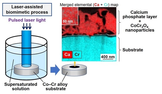
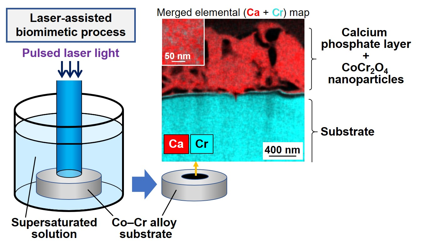
Formation of a Calcium Phosphate Layer with Immobilized Cobalt Chromite Nanoparticles on Cobalt−Chromium Alloy by a Laser-Assisted Biomimetic Process

Nanomaterials Research Institute, National Institute of Advanced Industrial Science and Technology (AIST), Central 5, 1-1-1 Higashi, Tsukuba, Ibaraki 305-8565, Japan
*
Author to whom correspondence should be addressed.
Appl. Sci. 2020, 10(16), 5584; https://doi.org/10.3390/app10165584
Submission received: 30 June 2020 / Revised: 3 August 2020 / Accepted: 6 August 2020 / Published: 12 August 2020
(This article belongs to the Special Issue Biomimetic Laser Processing Part II)

Abstract

:
The biocompatibility and osteoconductivity of metallic biomaterials can be achieved by calcium phosphate (CaP) coating. We recently developed a laser-assisted biomimetic (LAB) process for rapid and area-specific CaP coating on several materials. In the present study, the LAB process was applied to cobalt–chromium (Co−Cr) alloy, a metallic biomaterial widely used in orthopedic and dental applications. The LAB process was conducted by irradiation of unfocused pulsed laser light onto the substrate immersed in supersaturated CaP solution. The LAB-processed substrate formed CaP on the irradiated surface within only 5 min and was coated with a micron-thick CaP layer within 30 min by the effects of laser-induced surface modification and heating. Ultrastructural analysis with transmission electron microscopy revealed that the resultant CaP layer was integrated with the underlying substrate through two intermediate layers, an upper chromium oxide layer and a lower Co-rich (Cr-deficient) alloy layer. The CaP layer was loaded with a large number of cobalt chromite (CoCr2O4) nanoparticles. The results obtained offer new insights into the mechanism of CaP coating in the LAB process and future applications of LAB-processed Co−Cr alloys.

Graphical Abstract

1. Introduction

Calcium phosphate (CaP) is the major inorganic constituent of vertebrate hard tissues, i.e., bones and teeth. Certain types of CaP compounds, such as hydroxyapatite, β-tricalcium phosphate and octacalcium phosphate (OCP), exhibit both good biocompatibility and osteoconductivity, unlike other artificial materials [1,2]. Therefore, some CaP compounds have been used as biomaterials for hard tissue restoration and replacement. However, these CaP compounds cannot be used alone under high load-bearing conditions due to their insufficient fracture toughness. The coating of a thin CaP layer on tough and strong metallic materials is an effective approach to produce osteoconductive biomaterials that can be used under high load-bearing conditions.
Cobalt–chromium (Co−Cr) alloys are one of the most popular metallic biomaterials used in dental and orthopedic applications, such as joint replacements (hip, knee, etc.), fracture fixations and partial and complete dentures. Bulk Co−Cr alloys exhibit excellent mechanical properties [3], such as high mechanical strength, fracture toughness and strong resistance to fatigue and wear. In addition, they are chemically stable (corrosion resistant) and well tolerated in the body due to the passive oxide layer on their surfaces. However, Co−Cr alloys are categorized as bioinert materials; their osteoconductivity is insufficient compared to osteoconductive CaP compounds [4]. To remedy this shortcoming, various CaP coating techniques, such as plasma spraying [5], hot isostatic pressing [6], pressing/heating process [7], electrophoresis [8], pulsed laser deposition [9], laser-assisted powder fusion [10] and biomimetic process (supersaturated solution process) [11], have been applied to Co−Cr alloys.
Among these CaP coating techniques, biomimetic processes have drawn increasing attention in recent years. This is because biomimetic processes are conducted in a physiological reaction medium under normal pressure and temperature, and they are thus well suited to produce multifunctional CaP coatings combined with biofunctional substances (proteins, trace elements, antimicrobials, nucleic acids, etc.) [12,13]. Despite these advantages, biomimetic processes generally involve a time-consuming multi-step procedure: a surface modification step with specific functional groups and/or CaP seeds followed by an immersion step in supersaturated CaP solution for a certain period (hours to days) to allow CaP growth.
We recently developed a laser-assisted biomimetic (LAB) process [14,15] by refining earlier techniques [16,17] and achieved rapid (≤30 min) one-step CaP coating. In the LAB process, unfocused pulsed laser light is used to irradiate a substrate immersed in supersaturated CaP solution (so-called CP solution). The laser-irradiated region of the substrate is coated with CaP within 30 min via the combined effects of laser-induced surface modification and heating, whereas the non-irradiated region remains uncoated [14,18]. Therefore, the LAB process is capable of area-specific CaP coating. LAB-processed materials with CaP-coated surfaces exhibit superior cell compatibility compared to the untreated materials [14,18].
To date, the LAB process for CaP coating has been applied to several artificial materials that absorb laser light energy [14,15,18,19]. However, applicability of the LAB process to Co−Cr alloys has yet to be elucidated. If the LAB process is also applicable to Co−Cr alloys, it would be a useful new tool for tailoring the surface functionality of biomaterials composed of these alloys. The aim of this study was to demonstrate the feasibility of the LAB process for CaP coating on Co−Cr alloys and to shed light on the surface structure of the LAB-processed alloys. Disk-shaped substrates were prepared from a clinically approved Co−Cr alloy. The substrate was subjected to the LAB process using CP solution as a reaction medium for various times up to 30 min. The surface reactions on the laser-irradiated substrate were studied by surface and cross-sectional analyses.

2. Materials and Methods

2.1. Preparation of Co−Cr Alloy Substrates

A Co−Cr ingot bar [Co, 58 mass%; Cr, 30 mass%; Mo, 6 mass%; and others (Si, Fe, Al and Ca), 6 mass%] with a diameter of approximately 15 mm was purchased from Nihon Shika Kinzoku Co., Ltd., Izumiotsu, Japan. This product meets the Japanese Industrial Standard (JIS) T 6115 for dental casting cobalt–chromium alloys that is based on ISO 22674:2006. The Co−Cr ingot was cut into disk-shaped substrates with a thickness of 1 mm using a wire-electrical discharge machine. The Co−Cr alloy substrates were mechanically polished on one side using a barrel polishing machine and then manually with two SiC abrasive papers, #400 paper (ϕ = 37–144 µm) and #2000 paper (ϕ = 15–18 µm), sequentially. The substrates were washed ultrasonically with ultrapure water and ethanol, dried in air and stored in an electric desiccator before use. The polished surface of the substrate was used in the following experiments.

2.2. Preparation of CP Solution

The CP solution was prepared by a method described elsewhere [14,18,19]. Briefly, reagent grade chemicals (Nacalai Tesque, Inc., Kyoto, Japan) of NaCl (142 mM in final concentration), K2HPO4·3H2O (1.50 mM), 1M HCl (40 mM) and CaCl2 (3.75 mM) were successively added to ultrapure water under constant stirring. The solution was buffered to pH 7.40 at 25.0 °C with tris(hydroxymethyl)aminomethane (50 mM) and a necessary amount of 1M HCl. The prepared CP solution was sealed in a polystyrene bottle and stored at 4 °C for up to a month.

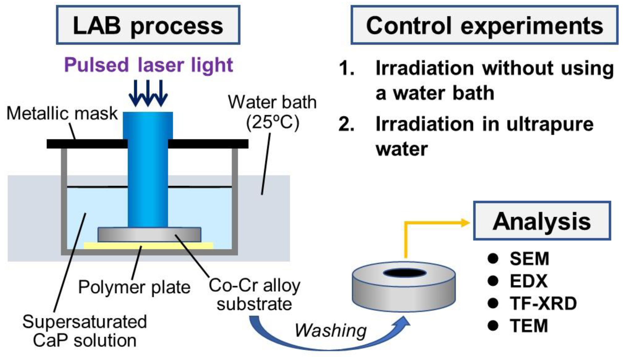
2.3. LAB Process for CaP Coating

Figure 1 shows a flow of the study outline. The LAB process was conducted as shown in Figure 1 under the same conditions used for other substrates [14,18,19]. The Co−Cr alloy substrate was placed on a polytetrafluoroethylene plate in a glass bottle. The CP solution (10 mL) was added to the bottle to fully immerse the substrate in the solution. The glass bottle was covered with a metallic mask with a 5-mm-diameter hole and set in a temperature-controlled water bath maintained at 25 °C. Pulsed laser irradiation was performed using the third harmonic (355 nm) output of a Nd:YAG laser (Quanta-Ray LAB-150-30, Spectra-Physics, Santa Clara, CA, USA) operated at 30 Hz. The output energy density (fluence) of the laser beam was adjusted to 4 W/cm2 (133 mJ/pulse/cm2). The energy density used was higher than the threshold (2 W/cm2) for inducing micro-roughening of the substrate surface (confirmed by scanning electron microscopy (SEM) after irradiation in ultrapure water for 5 min). A laser beam with a diameter of approximately 8 mm was used without focusing through the 5-mm-diameter hole of the metallic mask to irradiate a circular region (ca. 5 mm diameter) of the substrate surface. After irradiation for various times up to 30 min, the substrate was removed from the solution, gently washed with ultrapure water and dried in air.

2.4. Control Experiments

Two control experiments were performed to study effects of laser irradiation in the LAB process. First, to elucidate the laser heating effect, laser irradiation was conducted on the Co−Cr alloy substrate in the same manner as described in Section 2.3, except that the temperature-controlled water bath was not used. After irradiation for various times up to 30 min, the temperature of the CP solution was measured using an alcohol-filled thermometer. For comparison, temperature variation of the CP solution without the substrate (i.e., only a polytetrafluoroethylene sheet was placed in the bottle) with irradiation time was also measured.
Second, laser irradiation was performed on the Co−Cr alloy substrate immersed in ultrapure water (in place of the CP solution) in the same manner as described in Section 2.3 to examine the effect of laser-induced surface modification without involvement from CaP precipitation.

2.5. Surface Analysis

The surface of the Co−Cr alloy substrate was analyzed using the SEM system (XL30, FEI Company, Hillsboro, OR, USA) equipped with an energy-dispersive X-ray (EDX) analyzer (Genesis 2000, Ametek, Inc., Berwyn, PA, USA), a thin-film X-ray diffraction (TF-XRD) analyzer (M18X, MacScience, Yokohama, Japan) and a contact angle meter (Drop Master DM500, Kyowa Interface Science Co. Ltd., Niiza, Japan). Prior to the SEM-EDX analysis, the substrate was coated with carbon using a carbon coater (VC100S/100W, Vacuum device Co., Ltd., Mito, Japan). For the TF-XRD measurements, the glancing angle of the substrate was set to 1° against the direction of the incident beam of CuKα X-rays. In the contact angle measurements, an image of the water drop was captured 1 s after a 1-μL droplet of ultrapure water contacted the substrate surface.

2.6. Cross-Sectional Analysis

From the LAB-processed (30 min) substrate, cross-sectional ultra-thin samples were prepared by focused ion beam (FIB) processing using a Ga+ ion source (FB-2100, Hitachi High-Tech Corporation, Tokyo, Japan). Prior to the FIB processing, an oil-based ink was applied manually to the substrate surface as a soft protective cover. In the FIB processing, the substrate was coated with tungsten (W) using W(CO)6 gas to protect its surface. A cross-sectional sample was prepared, fixed on a copper (Cu) FIB lift-out grid and then thinned to approximately 100 nm.
The cross-sectional ultra-thin samples were analyzed using an analytical transmission electron microscopy (TEM) system (Tecnai Osiris, FEI Company, Hillsboro, OR, USA) operated at 200 kV. This system was equipped with an EDX spectrometer (Super-X system, FEI Company, Hillsboro, OR, USA) and a high-angle annular dark field (HAADF) scanning TEM (STEM) system with a probe diameter of less than 1 nm.

3. Results

3.1. Effects of Irradiation Time

The LAB process was effective for the facile CaP coating of the Co−Cr alloy substrate. SEM observation revealed that the laser-irradiated surface of the substrate was roughened at the microscale within 5 min (Figure 2a). As the irradiation time was increased to 30 min, the surface roughness increased further and a rugged micrograin-like structure was formed on the laser-irradiated surface. The untreated and LAB-processed substrates showed SEM-EDX peaks due to Co, Cr and Mo, which are the main component elements of the Co−Cr alloy substrate (Figure 2b). In addition to these peaks from the substrate, Ca and P peaks appeared on the LAB-processed (5 min) substrate. The Ca and P peaks increased in intensity with respect to the Co, Cr and Mo peaks as the irradiation time was extended from 5 to 30 min. The SEM-EDX results indicate that a certain type of CaP compound was precipitated on the laser-irradiated surface of the substrate within 5 min by the LAB process, and the amount of CaP precipitate increased with the irradiation time up to 30 min.
The LAB process provided area-specific CaP coating on the Co−Cr alloy substrate, as evidenced by a comparison of the irradiated and non-irradiated surfaces of the LAB-processed (30 min) substrate. After the LAB process for 30 min, CaP was precipitated on the laser-irradiated surface (inside the 5 mm diameter region) of the substrate (Figure 2a,b). In contrast, there were no apparent structural changes on the non-irradiated surface (outside the irradiated region) of the same substrate (Figure 2c). Neither Ca nor P was detected on the non-irradiated surface of this substrate by SEM-EDX measurements (data not shown). From these results, the area-specific coating capability of the LAB process using the Co−Cr alloy substrate was confirmed.
The LAB process caused not only CaP precipitation but also surface oxidation of the Co−Cr alloy substrate. The crystalline structures of the untreated and LAB-processed (30 min) surfaces were examined by TF-XRD. As shown in Figure 3, diffraction peaks ascribed to cobalt chromite (CoCr2O4) and chromium oxide (Cr2O3) were detected after the LAB process for 30 min, which suggests the presence of these metal oxides on the LAB-processed substrate surface. It was not clear whether cobalt oxides (CoO and Co3O4) coexisted on the LAB-processed substrate surface from the TF-XRD pattern. Despite the presence of CaP on this substrate (see Figure 2b), peaks due to crystalline CaP were not clearly detected, but, instead, a broad halo at around 30° was observed, which can be ascribed to amorphous CaP (ACP) [20]. These results suggest that the CaP precipitates formed on the LAB-processed substrate were composed mainly of ACP.

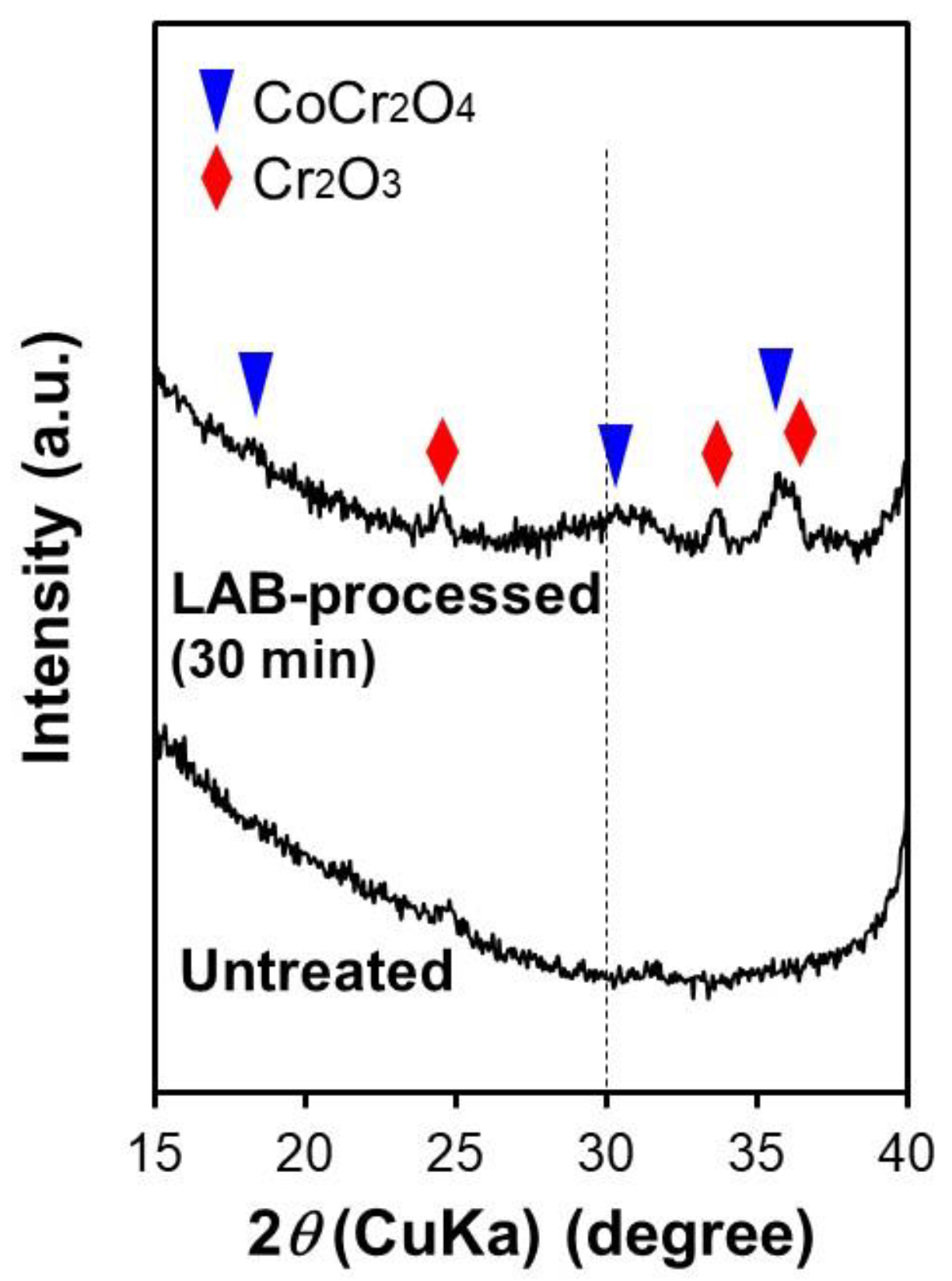
3.2. Effects of Laser Irradiation

Laser irradiation modified the surface of the Co−Cr alloy substrate while heating the reaction medium (CP solution). The laser heating effect was verified by a control experiment, in which the LAB process was performed on the Co−Cr alloy substrate in the absence of a temperature-controlled water bath. As shown in Figure 4, the temperature of the CP solution increased with the laser irradiation time for the Co−Cr alloy substrate. Without the substrate, the temperature remained almost constant during irradiation up to 30 min. The laser-induced surface modification of the substrate was confirmed by a control experiment in which laser irradiation was applied to the substrate in ultrapure water. The substrate surface was roughened at the micronscale within 5 min of irradiation in ultrapure water (Figure 5a), similarly to that in the CP solution (Figure 2a). The contact angle of a water droplet on the substrate significantly decreased after irradiation (Figure 5b). These results clarified that the Co−Cr alloy substrate undergoes surface modification, i.e., micro-roughening and wetting by laser irradiation in ultrapure water.

3.3. Ultrastructural Analysis of the Surface Layer

The CaP layer formed on the LAB-processed substrate was approximately 1‒2 µm thick and contained submicron-sized pores. Cross-sectional TEM observations (Figure 6a) revealed the presence of a micron-thick layer with a rugged surface between the LAB-processed (30 min) substrate (bottom dark region) and the top W coat (upper black region) that was applied for surface protection for the FIB processing. The micron-scale rugged structure of the layer surface in the cross-sectional TEM image (Figure 6a) corresponds to the micrograin-like structure in the top-view SEM image (lower right image in Figure 2a). The micron-thick layer on the substrate was composed mainly of CaP, as revealed by the cross-sectional STEM-EDX results (Figure 7). STEM-EDX elemental maps (Figure 7b,c) showed that Ca (red), P (green) and O (dark blue) constituted the matrix of the micron-thick layer over the dense Co−Cr alloy substrate composed of Co (purple), Cr (light blue) and Mo (brown). Within the CaP layer, irregularly shaped submicron-sized pores were present (Figure 6a and Figure 7a–c). According to the STEM-EDX spectrum (Figure 7d), the CaP layer also contained Cr and Co, although the distribution of Co in the CaP layer was not apparent in the elemental map (Figure 7b). The peak intensity of Cr with respect to that of Co in the STEM-EDX spectra (Figure 7d) was higher in the CaP layer than in the substrate. This observation was confirmed by quantitative STEM-EDX analysis at five different regions; the Cr/Co elemental ratio of the CaP layer was 2.0 ± 0.2, whereas that of the substrate was 0.5 ± 0.0. These results suggest that a Cr-rich compound different from the base Co−Cr alloy substrate was formed and contained in the CaP layer.
The CaP layer contained a large number of CoCr2O4 crystalline nanoparticles dispersed throughout the layer. The magnified TEM images of the CaP layer cross-section (Figure 6c,d) showed nanoparticles with diameters of a few tens of nanometers dispersed within the matrix layer. These nanoparticles have a crystalline structure according to the contrast in the dark-field TEM image (Figure 6d). Debye–Scherrer rings ascribed to CoCr2O4 were observed in the selected area electron diffraction (SAED) pattern (Figure 8b) of the CaP layer (circled area in Figure 8a). A broad ring (marked as *) with a d-spacing of approximately 0.29 nm is ascribed to ACP [20]. Figure 8c shows a high-resolution TEM (HRTEM) image obtained from a nanoparticle, which could be ascribed to crystalline CoCr2O4 through analysis of the fast Fourier transform (FFT) image (Figure 8d). From these results, the TF-XRD results (Figure 3) and the STEM-EDX results (Cr/Co elemental ratio = 2.0 ± 0.2), the nanoparticles dispersed in the CaP layer were identified as CoCr2O4.

3.4. Ultrastructural Analysis of the Substrate Interface

The CaP layer formed on the LAB-processed Co−Cr alloy substrate is attached to the substrate through two interfacial layers, an upper Cr2O3 layer and a lower Co-rich (Cr-deficient) alloy layer. Figure 9b,c shows cross-sectional STEM-EDX elemental maps of the interface between the CaP layer and the LAB-processed (30 min) Co−Cr alloy substrate. As shown in the merged elemental (Ca + Cr) map in Figure 9c, a Cr-rich layer was located above the Cr-deficient layer on the substrate. The upper Cr-rich interfacial layer contained a relatively high O content, although it contained almost no Co or Mo (Figure 9b,d). This Cr-rich layer had an O/Cr elemental ratio of approximately 1.5 from the peak intensities in Figure 9d. From these results and the TF-XRD results (Figure 3), the Cr-rich layer is considered to be composed of Cr2O3. On the other hand, the lower Cr-deficient layer was rich in Co, as shown by the Co and Cr elemental maps in Figure 9b. This Co-rich layer was oxygen-free and contained Mo as in the substrate (Figure 9d), suggesting that this layer was made up of non-oxidized Cr-deficient alloy. From the elemental (Cr) and merged elemental (Ca + Cr) maps (Figure 9b,c), Cr was distributed over the CaP layer. This is due to the dispersion of CoCr2O4 nanoparticles within the CaP layer.

4. Discussion

The LAB process is a facile process to produce an area-specific CaP coating on a Co−Cr alloy substrate, as reported for several other substrates [14,18,19]. Surface and cross-sectional analyses (Figure 2, Figure 6 and Figure 7) confirmed that the LAB-processed substrate induced CaP precipitation within only 5 min of surface irradiation and was coated with a micron-thick CaP layer within 30 min. In conventional biomimetic processes, a micron-thick CaP layer is formed only after a surface-modified substrate is immersed in a supersaturated CaP solution for hours to days [11,12,13]. Thus, the present LAB process, which can be accomplished with a single-step (one-pot) procedure within 30 min, is a simple and more practical process than conventional biomimetic processes. Note that the CP solution remained transparent without inducing homogeneous CaP precipitation during the LAB process up to 30 min. Therefore, CaP was precipitated heterogeneously at the laser-irradiated substrate surface without the sedimentation of homogeneously precipitated CaP particles. The use of a liquid CaP source (CP solution) makes the LAB process different from other laser-assisted CaP coating techniques, such as pulsed laser deposition [9] and laser-assisted powder fusion [10], both of which use solid CaP sources. A comparison with a non-irradiated surface of the LAB-processed (30 min) substrate revealed that the CaP coating was confined to the laser-irradiated surface; the non-irradiated surface was not affected, even in the same substrate (Figure 2c), which indicates the essential role of laser irradiation to induce CaP precipitation on the Co−Cr alloy substrate. A trace amount of CaP could possibly precipitate on the non-irradiated surface [21], although this was not detected under the tested analytical conditions.
The role of laser irradiation in the LAB process for the Co−Cr alloy substrate is considered to be similar to that reported for titanium metal, i.e., heating and surface modification (oxidative deformation) [19]. The heating effect due to laser irradiation was confirmed in the control experiment without the use of a temperature-controlled water bath; the temperature of the CP solution increased with the irradiation time for the Co−Cr alloy substrate (Figure 4). The CP solution does not readily absorb light at a wavelength of 355 nm [14]; therefore, the temperature increase observed in the CP solution was due to laser light absorption and light-to-heat energy conversion at the Co−Cr alloy surface. The heating of the solution has an accelerating effect on CaP precipitation by an increase in the mass transfer rate and the degree of supersaturation of the CP solution (solubility of apatite and OCP decreases with an increase in the medium temperature [22,23,24,25]). Besides the heating effect, laser irradiation has a surface-modifying effect on the Co−Cr alloy substrate. As shown in Figure 2a and Figure 3, the LAB process caused micro-roughening and oxidation of the substrate surface. This is caused by laser-induced thermal reactions such as melting, vaporization, ionization and oxidation. The Co−Cr alloy substrate showed a similar micro-roughening on its surface under laser irradiation in ultrapure water (Figure 5a). Cross-sectional STEM-EDX analyses (Figure 9) indicated the surface segregation of Co−Cr alloy on the LAB-processed substrate; a Cr-rich layer deficient in Co was identified above the Co-rich alloy layer deficient in Cr on the substrate. The surface segregation of alloys is a well-known phenomenon caused by the difference in surface energy between the components of the alloy and the heat of solution of the minority element into the bulk of the majority component [26]. In the LAB process, the Cr-rich layer segregated to the surface was oxidized into Cr2O3 (Figure 3 and Figure 9), most likely due to the incorporation of oxygen atoms from water in the CP solution. In contrast, the underlying Co-rich (Cr-deficient) alloy layer was not oxidized into cobalt oxides (Figure 9). This can be attributed to the disconnection between the Co-rich alloy layer and water (by the upper Cr-rich layer), as well as the higher ionization potential of Co (7.88 eV) than that of Cr (6.77 eV).
Ultrastructural analysis revealed that the CaP layer formed on the LAB-processed Co−Cr alloy substrate was composed mainly of ACP and loaded with a large number of CoCr2O4 nanoparticles. A putative mechanism for the formation of this nanocomposite layer can be described as follows. The CP solution is a metastable supersaturated CaP solution that remains transparent without inducing homogeneous CaP nucleation for a certain period. In such CaP solutions, nano-sized prenucleation CaP clusters can be present similar to solutes [27,28]. In the LAB process, these CaP nanoclusters may become densified to form post-critical amorphous nuclei at the substrate surface heated, modified and activated by laser irradiation. The ACP nuclei formed on the substrate surface grow further with irradiation time up to 30 min by the incorporation of CaP clusters and ions in the CP solution. While these reactions, CoCr2O4 nanoparticles are formed via laser ablation of the Co−Cr alloy substrate. Nanoparticle formation via laser ablation of target materials has been reported elsewhere [29]. It has also been reported that Co−Cr binary clusters along with Cr+ and Co+ clusters are formed via laser ablation of a Co−Cr target [30]. These clusters may be involved in the formation of the CoCr2O4 nanoparticles in the LAB process. The CoCr2O4 nanoparticles which were formed from the LAB-processed substrate were coprecipitated with CaP on the surface during the LAB process, which results in the formation of a nanocomposite layer that consists of a CaP matrix and dispersed CoCr2O4 nanoparticles.
In previous studies using other substrates, CaP layers formed on the LAB-processed (30 min) substrates contained crystalline CaP compounds, i.e., apatite and/or OCP [14,18,19]. This is natural considering the thermodynamic stability of CaP phases in neutral aqueous solution, i.e., initially formed non-crystalline CaP transforms spontaneously into the most stable crystalline apatite through transient CaP phases such as OCP [23,31]. However, in the case of the Co−Cr alloy substrate, the CaP layer formed on the surface retained the amorphous structure even after 30 min of the LAB process (Figure 3 and Figure 8). Furthermore, this CaP layer contained many micron-sized, irregularly shaped pores (Figure 6 and Figure 7). These were new phenomena specific to the Co−Cr alloy substrate found in this study. The mechanism underlying these phenomena is not clear. However, we consider that the CoCr2O4 nanoparticles immobilized within the CaP layer contributed to these phenomena by acting as a light-absorbing agent. According to previous reports, light-absorbing agents (metallic ions [32] and carbon [33]) immobilized on/in CaP particles dispersed in an aqueous solution absorb pulsed laser light, thereby heating the CaP matrix above the melting point [15]. In pulse intervals, the melted CaP droplets are quenched by the surrounding solution and solidified while retaining their amorphous structure. Such a laser process (known as a pulsed laser melting in liquid process [34]) has been used to produce a variety of submicron-sized spheres. The pulsed laser melting in liquid process produce hollow spheres in some cases where gases produced in the matrix are not released before final solidification [33,35,36]. Similar melting, quenching and gas-trapping reactions may also occur in the CaP layer on the LAB-processed Co−Cr alloy substrate with the light-absorbing effect of CoCr2O4 nanoparticles dispersed in the layer. Further studies are required to elucidate the reaction mechanism at the laser-irradiated surface of the Co−Cr alloy substrate in the CP solution.
In the LAB process, a Co−Cr alloy substrate was coated with a CaP (ACP) layer with immobilized CoCr2O4 nanoparticles. An ACP layer coated on implant materials has been reported to facilitate osseointegration with the surrounding bone tissue due to the osteoconductive nature of ACP [37,38]. The LAB-processed Co−Cr alloy is, therefore, likely to exhibit improved osteoconductivity compared to that of the untreated alloy, although this remains to be demonstrated. However, the effects of CoCr2O4 nanoparticles immobilized in the CaP layer are still unknown; they may raise the risk of side effects, or potentially exhibit additional functionality (e.g., for imaging, hyperthermia or photodynamic therapy) due to the magnetic, light-absorbing and photocatalytic properties of CoCr2O4 nanoparticles [39,40,41,42]. These are issues to be examined in future studies.

5. Conclusions

The LAB-processed Co−Cr alloy substrate formed CaP on the surface within only 5 min and was coated with a micron-thick CaP layer within 30 min by the effects of laser-induced surface modification and heating. The resultant CaP layer was composed of ACP and loaded with a large number of CoCr2O4 nanoparticles dispersed over the layer. The LAB process offers a facile new approach to functionalize Co−Cr alloy surfaces via coating with a CaP layer with immobilized CoCr2O4 nanoparticles, although further studies are needed to clarify the details of the coating mechanism and to elucidate the coating effects for future applications.

Author Contributions

Conceptualization, A.O.; methodology, A.O.; investigation, I.S. and K.K.; data curation, A.O., I.S. and K.K.; writing—original draft preparation, A.O.; writing—review and editing, K.K. and M.N.; visualization, A.O. and M.N.; project administration, A.O.; and funding acquisition, A.O. All authors have read and agreed to the published version of the manuscript.

Funding

This research was funded by KAKENHI JP20H04541 from Japan Society for the Promotion of Science (JSPS).

Acknowledgments

The authors thank N. Yoshizawa and N. Saito of AIST for TEM analyses.

Conflicts of Interest

The authors declare no conflict of interest.

References

  1. Habraken, W.; Habibovic, P.; Epple, M.; Bohner, M. Calcium phosphates in biomedical applications: Materials for the future? Mater. Today 2016, 19, 69–87. [Google Scholar] [CrossRef]
  2. Dorozhkin, S.V. Calcium orthophosphate bioceramics. Ceram. Int. 2015, 41, 13913–13966. [Google Scholar] [CrossRef]
  3. Jabbari, Y.S.A. Physico-mechanical properties and prosthodontic applications of Co-Cr dental alloys: A review of the literature. J. Adv. Prosthodont. 2014, 6, 138–145. [Google Scholar] [CrossRef] [Green Version]
  4. Navarro, M.; Michiardi, A.; Castaño, O.; Planell, J.A. Biomaterials in orthopaedics. J. R. Soc. Interf. 2008, 5, 1137–1158. [Google Scholar] [CrossRef] [Green Version]
  5. Grandfield, K.; Palmquist, A.; Gonçalves, S.; Taylor, A.; Taylor, M.; Emanuelsson, L.; Thomsen, P.; Engqvist, H. Free form fabricated features on CoCr implants with and without hydroxyapatite coating in vivo: A comparative study of bone contact and bone growth induction. J. Mater. Sci. Mater. Med. 2011, 22, 899–906. [Google Scholar] [CrossRef]
  6. Ergun, C.; Doremus, R.H.; Lanford, W.A. Interface reaction/diffusion in hydroxylapatite-coated SS316L and CoCrMo alloys. Acta Mater. 2004, 52, 4767–4772. [Google Scholar] [CrossRef]
  7. Ortiz, J.C.; Cortés, D.A.; Escobedo, J.C.; Almanza, J.M.; Muñiz, C.R.; Luna, J.S.; Rodríguez, N.A. Bioactive coating on a cobalt base alloy by heat treatment. Mater. Lett. 2011, 65, 329–332. [Google Scholar] [CrossRef]
  8. Shirdar, M.R.; Izman, S.; Kheimehsari, H.M.; Ahmad, N.; Ma’aram, A. Evaluation of mechanical and electrochemical properties of FHA-coated Co–Cr implant. Surf. Innov. 2017, 5, 90–96. [Google Scholar] [CrossRef]
  9. Khfagi, O.; Thovhogi, N.; Gihwala, D.; Maaza, M.; Mars, J.A. Synthesis of Co-Cr-Mo fluorapatite nano-composite coatings by pulsed laser deposition for dental applications. Mater. Sci. Appl. 2017, 8, 135–152. [Google Scholar] [CrossRef] [Green Version]
  10. Redhwi, I.; Lan, T.; Padalkar, S.; Shrotriya, P. Picosecond laser based additive manufacturing of hydroxyapatite coatings on cobalt chromium surfaces. Procedia Manufact. 2018, 26, 125–131. [Google Scholar] [CrossRef]
  11. Chen, C.; Yao, C.; Yang, J.; Luo, D.; Kong, X.; Chung, S.M.; Lee, I.S. Biomimetic apatite formed on cobalt-chromium alloy: A polymer-free carrier for drug eluting stent. Col. Surf. B Biointerf. 2017, 151, 156–164. [Google Scholar] [CrossRef] [PubMed]
  12. Surmenev, R.A.; Surmeneva, M.A.; Ivanova, A.A. Significance of calcium phosphate coatings for the enhancement of new bone osteogenesis? A review. Acta Biomater. 2014, 10, 557–579. [Google Scholar] [CrossRef] [PubMed]
  13. Lin, X.; de Groot, K.; Wang, D.; Hu, Q.; Wismeijer, D.; Liu, Y. A review paper on biomimetic calcium phosphate coatings. Open Biomed. Eng. J. 2015, 9, 56–64. [Google Scholar] [CrossRef] [PubMed]
  14. Oyane, A.; Sakamaki, I.; Shimizu, Y.; Kawaguchi, K.; Koshizaki, N. Liquid-phase laser process for simple and area-specific calcium phosphate coating. J. Biomed. Mater. Res. A 2012, 100A, 2573–2580. [Google Scholar] [CrossRef]
  15. Nakamura, M.; Oyane, A. Physicochemical fabrication of calcium phosphate-based thin layers and nanospheres using laser processing in solutions. J. Mater. Chem. B 2016, 4, 6289–6301. [Google Scholar] [CrossRef] [PubMed] [Green Version]
  16. Pecheva, E.; Petrov, T.; Lungu, C.; Montgomery, P.; Pramatarova, L. Stimulated in vitro bone-like apatite formation by a novel laser processing technique. Chem. Eng. 2008, 137, 144–153. [Google Scholar] [CrossRef]
  17. Lee, B.H.; Oyane, A.; Tsurushima, H.; Shimizu, Y.; Sasaki, T.; Koshizaki, N. A new approach for hydroxyapatite coating on polymeric materials using laser-induced precursor formation and subsequent aging. ACS Appl. Mater. Interf. 2009, 1, 1520–1524. [Google Scholar] [CrossRef]
  18. Oyane, A.; Nakamura, M.; Sakamaki, I.; Shimizu, Y.; Miyata, S.; Miyaji, H. Laser-assisted wet coating of calcium phosphate for surface-functionalization of PEEK. PLoS ONE 2018, 13, e0206524. [Google Scholar] [CrossRef] [Green Version]
  19. Mahanti, M.; Nakamura, M.; Pyatenko, A.; Sakamaki, I.; Koga, K.; Oyane, A. The mechanism underlying calcium phosphate precipitation on titanium via ultraviolet, visible, and near infrared laser-assisted biomimetic process. J. Phys. D Appl. Phys. 2016, 49, 304003. [Google Scholar] [CrossRef]
  20. Dorozhkin, S.V. Amorphous calcium orthophosphates: Nature, chemistry and biomedical applications. Int. J. Mater. Chem. 2012, 2, 19–46. [Google Scholar] [CrossRef]
  21. Hanawa, T.; Hiromoto, S.; Asami, K. Characterization of the surface oxide film of a Co–Cr–Mo alloy after being located in quasi-biological environments using XPS. Appl. Surf. Sci. 2001, 183, 68–75. [Google Scholar] [CrossRef]
  22. McDowell, H.; Gregory, T.M.; Brown, W.E. Solubility of Ca5(PO4)3OH in the system Ca(OH)2–H3PO4–H2O at 5, 15, 25 and 37 °C. J. Res. Natl. Bur. Stand. A Phys. Chem. 1977, 81A, 273–281. [Google Scholar] [CrossRef]
  23. Van Kemenade, M.J.J.M.; de Bruyn, P.L. A kinetic study of precipitation from supersaturated calcium phosphate solutions. J. Col. Interf. Sci. 1987, 118, 564–585. [Google Scholar] [CrossRef]
  24. Tung, M.S.; Eidelman, N.; Sieck, B.; Brown, W.E. Octacalcium phosphate solubility product from 4 to 37 °C. J. Res. Natl. Bur. Stand. 1988, 93, 613–624. [Google Scholar] [CrossRef]
  25. Christoffersen, M.R.; Christoffersen, J.; Kibalczyc, W. Apparent solubilities of two amorphous calcium phosphates and of octacalcium phosphate in the temperature range 30–42 °C. J. Cryst. Growth 1990, 106, 349–354. [Google Scholar] [CrossRef]
  26. Boom, R.; de Boer, F.R. Energy effects in bulk metals. In Encyclopedia of Materials: Science and Technology, 2nd ed.; Elsevier: Amsterdam, The Netherlands, 2006; pp. 1–7. [Google Scholar]
  27. Onuma, K.; Ito, A. Cluster growth model for hydroxyapatite. Chem. Mater. 1998, 10, 3346–3351. [Google Scholar] [CrossRef]
  28. Dey, A.; Bomans, P.H.H.; Müller, F.A.; Will, J.; Frederik, P.M.; de With, G.; Sommerdijk, N.A.J.M. The role of prenucleation clusters in surface-induced calcium phosphate crystallization. Nat. Mater. 2010, 9, 1010–1014. [Google Scholar] [CrossRef]
  29. Zeng, H.; Du, X.W.; Singh, S.C.; Kulinich, S.A.; Yang, S.; He, J.; Cai, W. Nanomaterials via laser ablation/irradiation in liquid: A review. Adv. Funct. Mater. 2012, 22, 1333–1353. [Google Scholar] [CrossRef]
  30. Burnin, A.; BelBruno, J.J.; Gibson, U.J. Evidence of chromium-cobalt binary cluster formation by pulsed laser evaporation. Inter. J. Mass Spect. 2015, 380, 7–11. [Google Scholar] [CrossRef] [Green Version]
  31. Habraken, W.J.E.M.; Tao, J.; Brylka, L.J.; Friedrich, H.; Bertinetti, L.; Schenk, A.S.; Verch, A.; Dmitrovic, V.; Bomans, P.H.H.; Frederik, P.M.; et al. Ion-association complexes unite classical and non-classical theories for the biomimetic nucleation of calcium phosphate. Nat. Comm. 2013, 4, 1–12. [Google Scholar] [CrossRef] [Green Version]
  32. Nakamura, M.; Oyane, A.; Shimizu, Y.; Miyata, S.; Saeki, A.; Miyaji, H. Physicochemical fabrication of antibacterial calcium phosphate submicrospheres with dispersed silver nanoparticles via coprecipitation and photoreduction under laser irradiation. Acta Biomater. 2016, 46, 299–307. [Google Scholar] [CrossRef]
  33. Nakamura, M.; Oyane, A.; Sakamaki, I.; Shimizu, Y.; Koga, K.; Koshizaki, N. A physicochemical process for fabricating submicrometer hollow fluorescent spheres of Tb3+-incorporated calcium phosphate. RSC Adv. 2015, 5, 22620–22624. [Google Scholar] [CrossRef]
  34. Wang, H.; Pyatenko, A.; Kawaguchi, K.; Li, X.; Swiatkowska-Warkocka, Z.; Koshizaki, N. Selective pulsed heating for the synthesis of semiconductor and metal submicrometer spheres. Angew. Chem. Int. Ed. 2010, 49, 6361–6364. [Google Scholar] [CrossRef]
  35. Li, X.; Shimizu, Y.; Pyatenko, A.; Wang, H.; Koshizaki, N. Carbon-assisted fabrication of submicrometre spheres for low-optical-absorbance materials by selective laser heating in liquid. J. Mater. Chem. 2011, 21, 14406–14409. [Google Scholar] [CrossRef]
  36. Li, X.; Shimizu, Y.; Pyatenko, A.; Wang, H.; Koshizaki, N. Tetragonal zirconia spheres fabricated by carbon-assisted selective laser heating in a liquid medium. Nanotechnology 2012, 23, 115602. [Google Scholar] [CrossRef]
  37. Yokota, S.; Nishiwaki, N.; Ueda, K.; Narushima, T.; Kawamura, H.; Takahashi, T. Evaluation of thin amorphous calcium phosphate coatings on titanium dental implants deposited using magnetron sputtering. Implant. Dent. 2014, 23, 343–350. [Google Scholar] [CrossRef]
  38. Masamoto, K.; Fujibayashi, S.; Yabutsuka, T.; Hiruta, T.; Otsuki, B.; Okuzu, Y.; Goto, K.; Shimizu, T.; Shimizu, Y.; Ishizaki, C.; et al. In vivo and in vitro bioactivity of a ‘‘precursor of apatite” treatment on polyetheretherketone. Acta Biomater. 2019, 91, 48–59. [Google Scholar] [CrossRef]
  39. Dutta, D.P.; Manjanna, J.; Tyagi, A.K. Magnetic properties of sonochemically synthesized CoCr2O4 nanoparticles. J. Appl. Phys. 2009, 106, 043915. [Google Scholar] [CrossRef]
  40. Rath, C.; Mohanty, P.; Banerjee, A. Magnetic properties of nanoparticles of cobalt chromite. J. Magn. Magn. Mater. 2011, 323, 1698–1702. [Google Scholar] [CrossRef]
  41. Gingasu, D.; Mindru, I.; Culita, D.C.; Patron, L.; Calderon-Moreno, J.M.; Osiceanu, P.; Preda, S.; Oprea, O.; Parvulescu, V.; Teodorescu, V.; et al. Structural, magnetic and catalytic properties of cobalt chromite obtained through precursor method. Mater. Res. Bul. 2015, 62, 52–64. [Google Scholar] [CrossRef]
  42. Fardood, S.T.; Forootan, R.; Moradnia, F.; Afshari, Z.; Ramazani, A. Green synthesis, characterization, and photocatalytic activity of cobalt chromite spinel nanoparticles. Mater. Res. Exp. 2020, 7, 015086. [Google Scholar] [CrossRef]
Figure 1. Flow of the study outline and schematic of the experimental setup for the laser-assisted biomimetic (LAB) process for the cobalt–chromium (Co−Cr) alloy substrate.
Applsci 10 05584 g001
Figure 2. (a) Scanning electron microscopy (SEM) images and (b) energy-dispersive X-ray (EDX) spectra of the laser-irradiated surfaces of the untreated and LAB-processed (5, 10 and 30 min) Co−Cr alloy substrates. (c) SEM image of the non-irradiated surface of the LAB-processed (30 min) Co−Cr alloy substrate. The C peak in (b) is derived from the carbon coating that was applied to the substrate surface prior to the SEM-EDX analysis.
Applsci 10 05584 g002
Figure 3. Thin-film X-ray diffraction (TF-XRD) patterns of the surfaces of the untreated and LAB-processed (30 min) Co−Cr alloy substrates.
Applsci 10 05584 g003
Figure 4. Variation of the temperature of the supersaturated calcium phosphate (CaP) solution (CP solution) with the laser irradiation time for the Co−Cr alloy substrate (without using the temperature-controlled water bath).
Applsci 10 05584 g004
Figure 5. (a) SEM images and (b) contact angles of water droplets of the surfaces of the Co−Cr alloy substrates after laser irradiation in ultrapure water for 0 (untreated), 5, 10 and 30 min.
Applsci 10 05584 g005
Figure 6. (ac) Bright-field and (d) dark-field transmission electron microscopy (TEM) images of the ultra-thin cross-section of the CaP layer formed on the LAB-processed (30 min) Co−Cr alloy substrate. The W top coat in (a) was prepared during focused ion beam (FIB) processing. The image in (c) corresponds to that in (d).
Applsci 10 05584 g006
Figure 7. (a) High-angle annular dark field (HAADF) image, (b) scanning TEM (STEM)-EDX elemental (Ca, P, O, Co, Cr and Mo) maps and (c) STEM-EDX merged elemental (Ca + Cr) map of the ultra-thin cross-section of the LAB-processed (30 min) Co−Cr alloy substrate (CaP-coated surface). (d) STEM-EDX spectra obtained from each region in (c). The Cu peaks in (d) are derived from the grid that was used to mount the cross-sectional ultra-thin sample, and the C peak in (d) is derived from the oil-based ink (soft protective cover) that was applied to the substrate surface prior to the FIB processing.
Applsci 10 05584 g007
Figure 8. (a) Bright-field TEM image of the ultra-thin cross-section of the CaP layer formed on the LAB-processed (30 min) Co−Cr alloy substrate; (b) selected area electron diffraction (SAED) pattern obtained from the circled area in (a); (c) high-resolution TEM (HRTEM) image obtained from the nanoparticles dispersed in (a); and (d) fast Fourier transform (FFT) pattern of (c).
Applsci 10 05584 g008
Figure 9. (a) HAADF image, (b) STEM-EDX elemental (Ca, P, O, Co, Cr and Mo) maps and (c) STEM-EDX merged elemental (Ca + Cr) map of the ultra-thin cross-section of the LAB-processed (30 min) Co−Cr alloy substrate (interface with the CaP layer). (d) STEM-EDX spectra obtained from each region in (c). The Cu peaks in (d) are derived from the grid that was used to mount the cross-sectional ultra-thin sample. The C peak in (d) is derived from the oil-based ink (soft protective cover) that was applied to the substrate surface prior to the FIB processing.
Applsci 10 05584 g009

