Article

Design of a Novel Magnetorheological Damper Adaptable to Low and High Stroke Velocity of Vehicle Suspension System

1
Smart Structures and Systems Laboratory, Department of Mechanical Engineering, Inha University, Incheon 22212, Korea
2
Mechatronics Group, Department of Mechanical Engineering, Ilmenau University of Technology, 98684 Ilmenau, Germany
*
Authors to whom correspondence should be addressed.
Appl. Sci. 2020, 10(16), 5586; https://doi.org/10.3390/app10165586
Submission received: 30 June 2020 / Revised: 29 July 2020 / Accepted: 10 August 2020 / Published: 12 August 2020
(This article belongs to the Section Acoustics and Vibrations)

Abstract

:
In this study, a new class of magnetorheological (MR) damper, which can realize desired damping force at both low and high speeds of vehicle suspension systems, is proposed and its salient characteristics are shown through computer simulations. Unlike conventional MR dampers, the proposed MR damper has a specific pole shape function and therefore the damping coefficient is changed by varying the effective area of the main orifice. In addition, by controlling the opening or closing the bypass orifice, the drastic change of the damping coefficient is realizable. After briefly describing the operating principle, a mathematical modeling is performed considering the pole shape function which is a key feature of the proposed MR damper. Then, the field-dependent damping force and piston velocity-dependent characteristics are presented followed by an example on how to achieve desired damping force characteristics by changing the damping coefficient and slope breaking point which represents the bilinear damping property.

1. Introduction

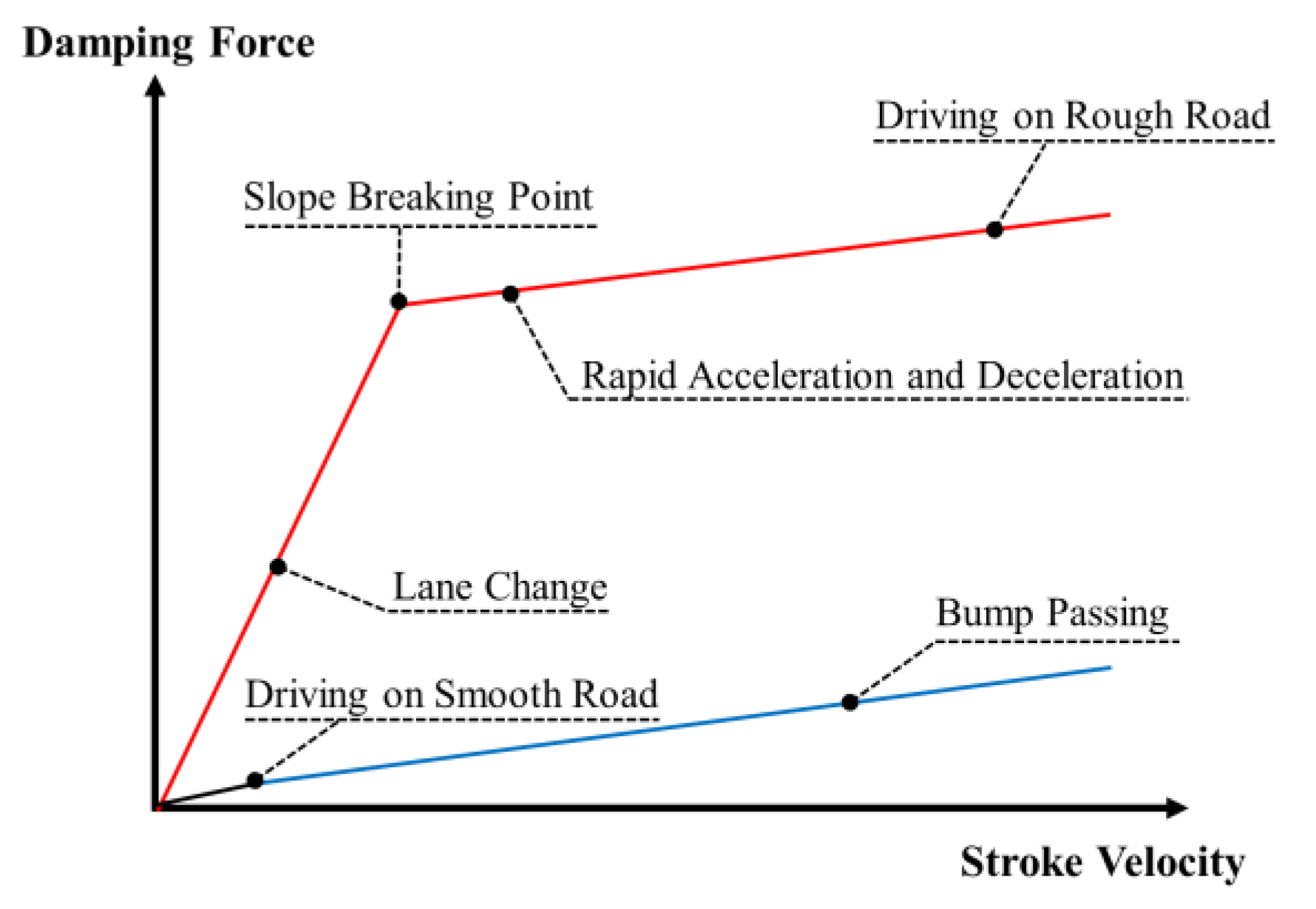
The main functions of the vehicle suspension system include the supporting vehicle’s static weight, isolating the body from road disturbances for good ride quality and keeping safe road holding and handling on various driving conditions for high steering stability. In general, the suspension system consists of an elastic element of the spring and viscous element of the damper (or shock absorber). Since the damper plays a crucial role for the ride comfort and road holding, the suspension system is classified depending upon the type of the damper—passive, semi-active, and active suspension system. In the case of the passive damper, the damping characteristics are determined by the combination of the disc springs in piston valve. To minimize the trade-offs between the ride comfort and road holding, optimal damping characteristics of the passive damper are achieved based on numerous road tests with the conditions as shown in Figure 1 [1,2]. It is seen from this figure that there is a slope breaking point (SBP) at a specific stroke velocity (or piston velocity) where the damping coefficient drastically changes and different damping characteristics are realized before and after SBP. It is known that to accomplish both good ride comfort and road holding properties, high damping coefficient is required in low stroke velocity range, while low damping coefficient is required in high stroke velocity range. Since the passive damper has a limitation to satisfy this trade-off requirement, active dampers have been proposed to overcome the limitation [3,4,5,6,7,8]. Unlike the passive damper, excellent driving performances with active dampers can be ensured by controlling the damping force according to various external conditions. However, despite the performance enhancement, active damper requires large power, many sensors and sophisticated control algorithm to avoid the instability. Thus, recently, the semi-active dampers are actively developing in several different ways. One attractive way to devise the semi-active damper is to use a magnetorheological (MR) fluid whose rheological properties can be quickly controlled by external magnetic field [9,10,11,12,13,14,15,16,17,18,19]. Some of semi-active dampers utilizing MR fluid (MR damper in short) are practically implemented on several vehicle suspension systems and commercially available [20].
MR dampers have been designed using different flow motion of MR fluid [21,22,23]. In fact, there are four operating flow motions—flow mode, shear mode, squeeze mode, and pinch mode. In the flow mode, MR fluid flows between two fixed plates to create the field-dependent pressure drop. In the shear mode, the shear stress is occurred from the flow motion between the moving plate and the fixed plate. In the squeeze mode, the force is generated in a direction parallel to the magnetic field. The pinch mode can be achieved by utilizing the non-magnetic spacer that separates the magnetic poles. Thus, the generated force depends on the magnetic field intensity which can control the flow rate of MR fluid. So far, numerous MR dampers have been developed based on flow mode and shear modes for the vehicle suspension system. However, the research on the pinch mode-based MR damper is relatively rare [24,25]. 
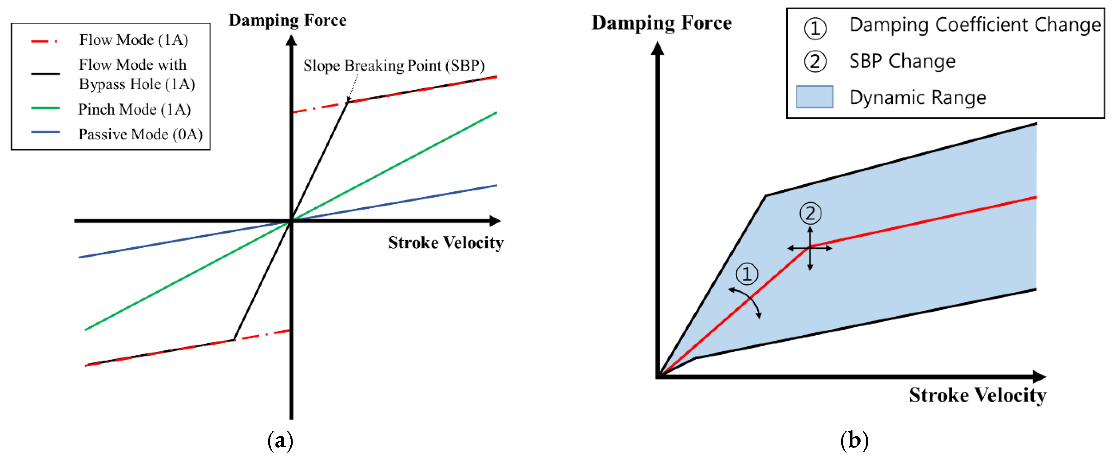
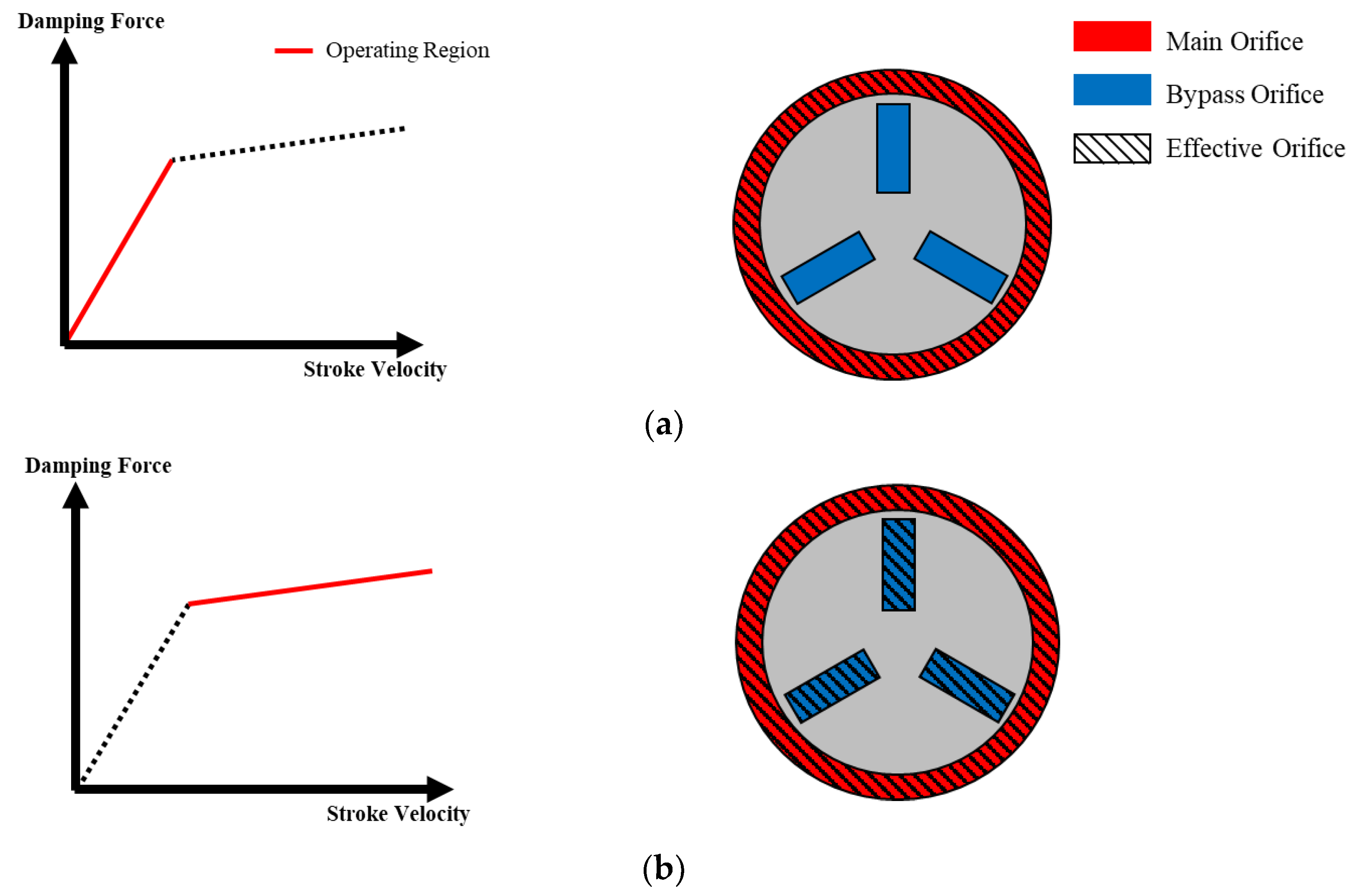
Figure 2a shows the damping characteristics of three different MR dampers—flow mode, flow mode with bypass hole, and pinch mode. In the flow and shear mode MR damper, the desired damping force is obtained by controlling the yield stress of MR fluid. To avoid the discontinuity at low (almost zero) stroke velocity of the flow mode, the bypass holes are added to the flow-mode MR damper. This type is more practicable than the flow mode only [26]. However, even though the damping coefficient can be changed according to the stroke velocity range, there is a limit to control the desired SBP. As observed from the characteristic of the flow mode, it is difficult to obtain a high damping coefficient at high speed. Moreover, it is hard to obtain a high damping coefficient at the low speed from the pinch-mode MR damper only.
Consequently, the technical originality of this work is to propose a novel type of MR damper which can control both the damping coefficient and the SBP to achieve desired damping characteristics at high and low speeds. Figure 2b shows the damping characteristics of the proposed MR damper. Unlike conventional MR dampers operated by the flow mode only or pinch mode only, the proposed MR damper has a specific pole shape function (PSF) and hence the damping coefficient can be easily controlled by varying the magnetic-effective area of the main orifice. In addition, the SBP can be tuned by opening or closing the bypass orifices. In this paper, MRD-PSF stand for the proposed MR damper with PSF in the effective pole. To demonstrate the effectiveness of the proposed damper, a mathematical modeling to achieve the damping force is carried out, followed by the analysis of the damping force characteristics as functions of the input current (or magnetic field intensity) and piston velocity. In addition, it is shown that three different desired damping forces are realized by changing both the coefficient slope, SBP, and the input current. The subsequent section introduces the configuration of MRD-PSF and the principles of the damping coefficient change and the SBP change, followed by the mathematical modeling in Section 3. In this section, several models are provided to analyze the flow motions through the main orifice and bypass orifice. In Section 4, the field-dependent damping characteristics of MRD-PSF are evaluated by presenting control method of the damping coefficient and the SBP to achieve the desired damping force. The last section concludes the main results achieved form the proposed new MR damper and a brief remark for future work.

2. Configuration and Operating Principle

2.1. Structural Configuration

The schematic configuration of MRD-PSF is shown in Figure 3a. The MRD-PSF consists of basic elements: piston rod, piston, housing, and floating piston. It is a mono-tube type damper which is divided into upper and lower chamber by the piston and additionally air chamber by the floating piston. By constructing air chamber using a floating piston, it has the following advantages: (ⅰ) prevention of reduction of MR effect through the separation of MR fluid and air, (ⅱ) prevention of cavitation problem due to increased inner pressure, and (ⅲ) compensation of volume variation caused from the piston stroke. The configuration of the core part is shown in Figure 3b,c. It has a main orifice (annular orifice) to control the main damping coefficient and a bypass orifice (rectangular duct) to control the SBP, respectively. Each control part consists of ferromagnetic materials that form a magnetic path, and paramagnetic materials that inhibit the magnetic path formation. The use of two different materials help the concentration of magnetic field and provide independent coils for control. The main orifice has a unique pole shape to make the change of damping coefficient. The bypass orifice has three rectangular ducts of the same shape to obtain a low damping coefficient after the SBP. Two orifices have MR valve in flow mode. In the case of the conventional MR damper, a pole, in which MR effect acts, is a cylindrical shape made of a ferromagnetic material. So, the effective pole length along the perimeter is uniform. However, the main orifice of MRD-PSF has the spiral shaped pole and magnetic shielding ring. The magnetic shielding ring is a design element as a paramagnetic material. It can block the magnetic field and change the effective pole length along the circumferential direction. The bypass orifice of MRD-PSF is composed of three rectangular ducts which have a same effective pole length. The results of the magnetic field analysis are shown in Figure 4. According to the result of the magnetic field analysis on Cross Section 1 (Figure 4b) and Cross Section 2 (Figure 4c), it is possible to independently control the magnetic field intensity of each control part, respectively. As shown in Figure 4d, it is seen that the magnetic field intensity at the pole of the main orifice is almost same around the circumference when a constant current is applied.

2.2. Principle of Damping Coefficient Change

Damping force is generated by the flow motion of MR fluid through the narrow orifice caused by the damper stroke. A pressure drop occurs in each orifice when the fluid flows resulting in the creation of the pressure difference between the upper and lower chambers. The two orifices can be independently controlled by the magnetic field, and the flow rate through each orifice is determined by the magnetic field intensity. In the orifices, a total pressure drop is composed of pressure drops due to the viscosity and the field-dependent yield stress of MR fluid. If the magnetic field intensity becomes strong enough and the pressure drop due to the yield stress of the fluid becomes larger than the pressure difference between the front and back of the orifice. In this case, a block-up phenomenon may occur in which the MR fluid does not flow. Using this phenomenon, the opening and closing of two orifices can be controlled and the damping coefficient can be changed by blocking the main orifice partially and adjusting the effective orifice area. Figure 5 shows the flow rate profile through the main orifice of MRD-PSF depending on the magnitude of magnetic field. In the case of the conventional MR damper, the pole shape is cylindrical where effective pole lengths along the circumferential direction are constant. So, the flow rate per unit length is constant although the magnetic field intensity increases. However, in the case of MRD-PSF, the pole shape is the specific pole shape where effective pole lengths along the circumferential direction are different.Thereby, there can be two regions as the magnetic field intensity increases: one where the fluid flows and the other where the fluid does not flow. In addition, a gradient of the flow rate per unit length occurs. In other words, a partial block-up occurs depending on the magnitude of the magnetic field intensity and hence the damping coefficient can be controlled ultimately.

2.3. Principle of SBP Change

The low damping coefficient can be obtained by increasing the effective orifice area. To this end, the proposed MRD-PSF has the additional bypass orifice. Figure 6 shows the effective orifice area depending on the stroke velocity and the damping coefficient. In the low stroke velocity region requiring a high damping coefficient, the bypass orifice is closed using the block-up phenomenon and the fluid flows only through the main orifice. In the high stroke velocity region requiring a low damping coefficient, the bypass orifice is opened to obtain wide effective orifice area. Furthermore, by varying the magnetic field intensity in the bypass orifice, it is possible to control onset of opening or closing of the bypass orifice, which directly indicates that the SBP can be controlled.

3. Damping Force Modeling

To find the relationship between the stroke velocity and the damping force of MR damper, the behavior of MR fluid flowing through orifices is analyzed. To model the behavior of MR fluid, assumptions and simplifications are made as follows: (i) the flow is a fully developed laminar flow, (ii) the fluid is incompressible, (iii) the parallel plate model is used, and iv) one-dimensional analysis is considered. In general, the behavior of MR fluid is assumed to follow the Bingham model in which a total stress of MR fluid is composed of the field-dependent yield stress and the field-independent viscous stress. If the total stress is higher than the field-dependent yield stress, the flow is governed by the Bingham equation [21]:
τ ( H , γ ˙ ) = τ y ( H )   s g n   γ ˙ + η γ ˙ ,     τ > τ y
where, H is the magnetic field intensity, γ ˙ is the shear rate, and η is the viscosity of MR fluid. If the total stress is lower than the field-dependent yield stress, the fluid behaves like viscoelastic material:
τ = G γ ,     τ < τ y
where, G is the complex modulus and γ 
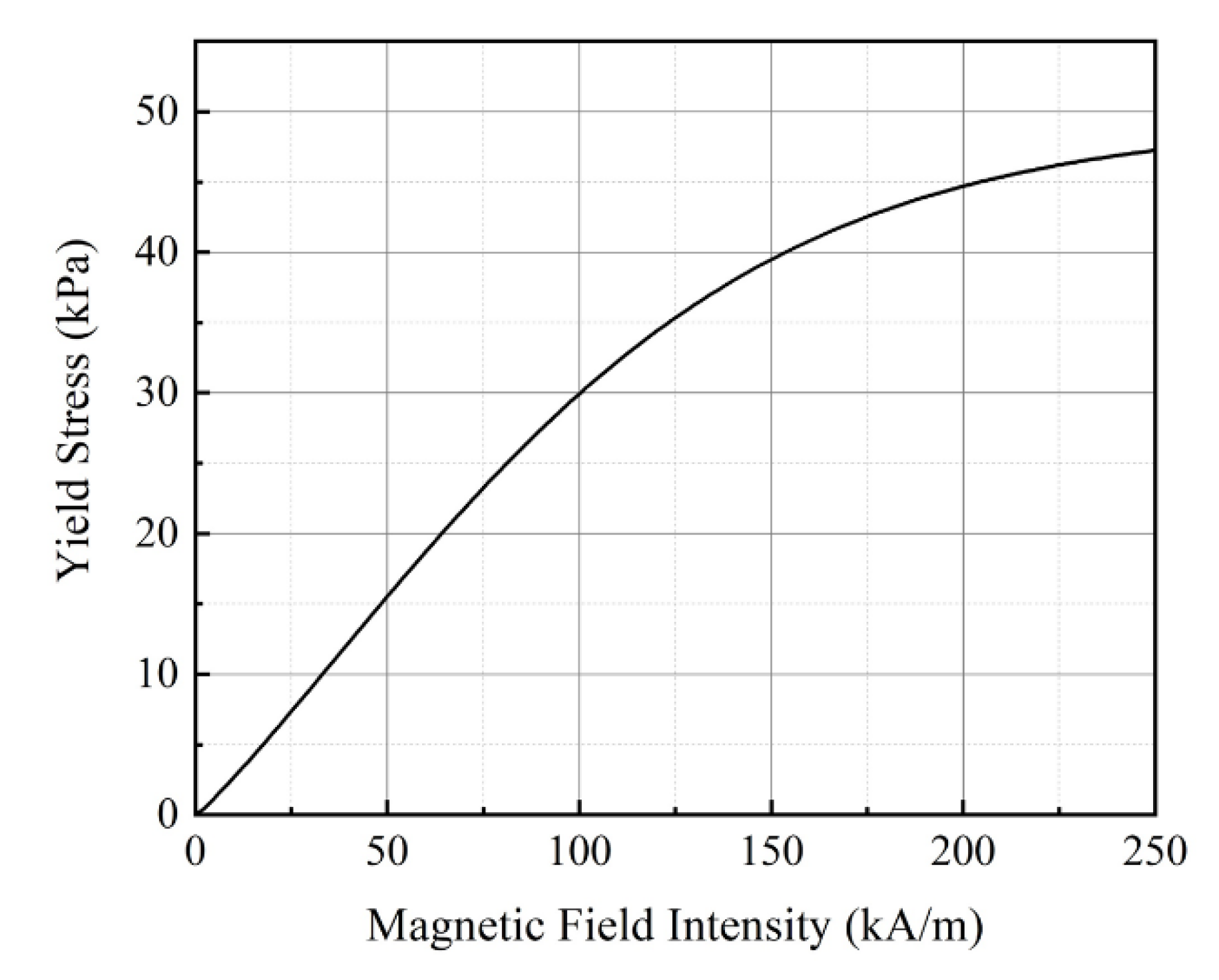
is the shear strain. In this study, one of commercial MR fluids (Lord Corp., MRF-132DG [27]) is used as working fluid. Figure 7 shows the magnetic property of MR fluid adopted in this work. From the plot, the field-dependent yield stress τ y can be expressed using the fourth-order polynomial equation as follows.
τ y = 1.754 × 10 8 H 4 8.989 × 10 6 H 3 + 6.957 × 10 4 H 2 + 0.3055 H
The above equation is obtained by the curve fitting of the measured data shown in Figure 7. In the previous works, various methods of non-dimensional analysis have been studied for mathematical modeling of MR damper [28,29,30,31,32]. It is noted that the proposed MR damper is also analyzed based on the non-dimensional manner. It is noted that since the proposed MRD-PSF consists several flow modes the total damping force should be calculated by considering the flow motion of the parallel plate, the flow motion of the main orifice and bypass orifices

3.1. Flow Motion of the Parallel Plate Model

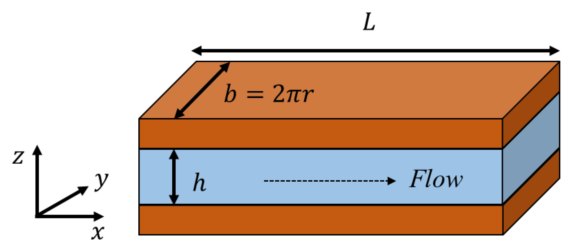
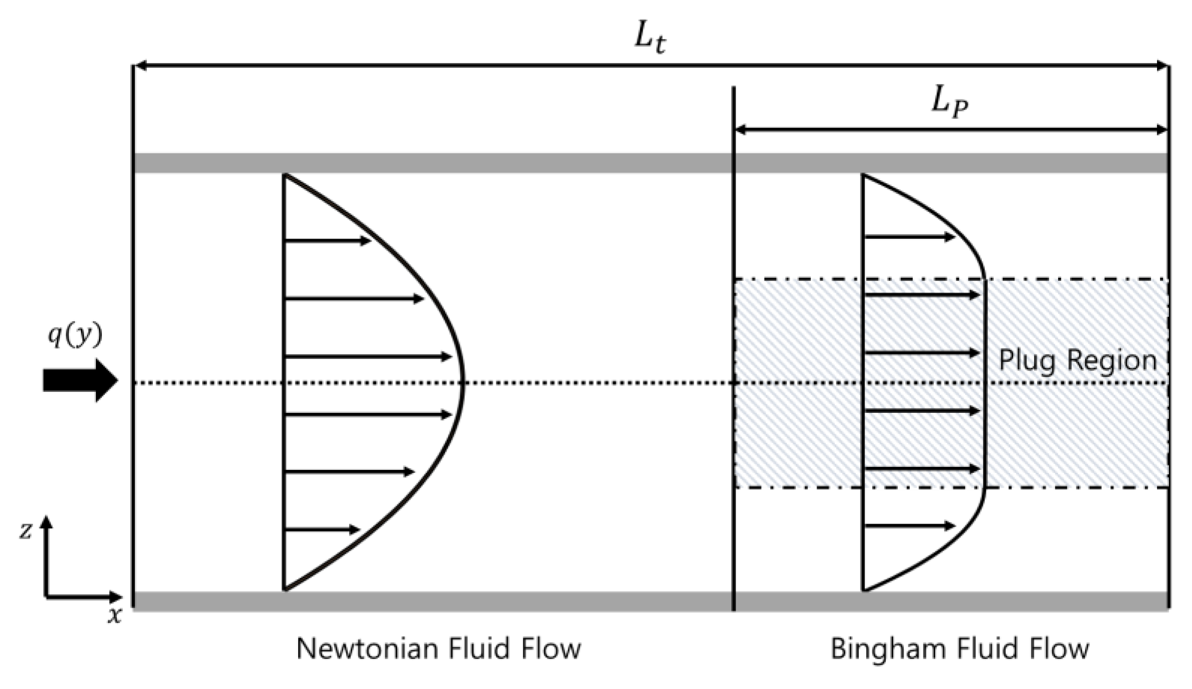
Firstly, the approximate parallel plate model is considered to analyze the flow of MR fluid through general orifice. Figure 8 shows the schematic configuration of the parallel plate model and the corresponding coordinate system. There are dimensions where L is the effective pole length, b is the approximate width, and h is the gap size of orifice. The x-axis represents the direction of flow, the y-axis is the direction along the circumferential direction and z-axis is the direction of the applied magnetic field. If the flow of MR fluid through orifice is steady and the fully developed laminar flow, the behavior of MR fluid can be analyzed using the Newtonian fluid flow region and the Bingham fluid flow region as shown in Figure 9.
The pressure drop Δ P t depending on the flow rate per unit length q ( y ) is derived as follows.
p N ( L t L p ) + 2 p y L p = Δ P t
where, p N is the pressure drop gradient due to Newtonian fluid flow, p y is the pressure drop gradient due to Bingham fluid flow, L t is the total length of orifice and L p is the effective pole length. The pressure drop gradient due to Bingham fluid flow with flow mode is numerically calculated by the following equation [28].
p y 3 ( 12 η h 3 q + 3 τ y h ) p y 2 + 4   ( τ y h ) 3 = 0
To simplify and parameterize problems, the non-dimensional parameters are used as follows.
Ρ p y p Ν , Τ p c 2 p Ν , Φ p y p C , Ν p N p C , p Ν = 12 η h 3 q , p C = 2 τ y h
where, p C is the pressure drop gradient in plug region of Bingham fluid flow, Ρ and Τ are the non-dimensional parameters based on p Ν , Φ , and Ν are non-dimensional parameters based on p C . Using these parameters, Equation ( 5 ) can be expressed as follows.
Ρ 3 ( 1 + 3 Τ ) Ρ 2 + 4 Τ 3 = 0 ,     Φ 3 ( Ν + 3 2 ) Φ 2 + 1 2 = 0
To simplify the numerical calculations, the approximate solution is given as follows [32].
Ρ = 1 + 2.07 Τ + Τ 1 + 0.4 Τ ,     Φ = Ν + 1.035 + Ν 2 Ν + 0.4

3.2. Flow through the Main Orifice

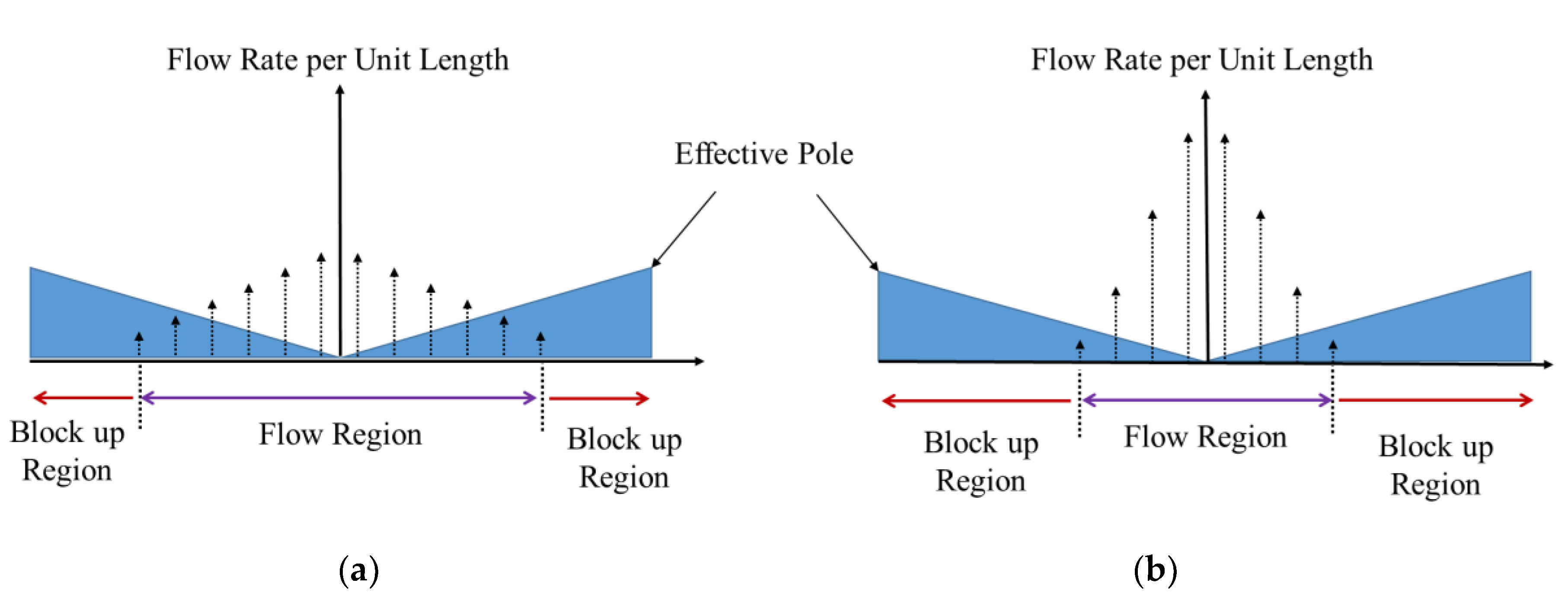
The main orifice of MRD-PSF has two effective poles controlled by one coil. And the effective pole length on the unit section is determined by the pole shape. Figure 10 shows the behaviors of MR fluid in the main orifice on the unit section. Using the equations derived in the previous section, the relationship between the pressure drop and flow rate in the main orifice can be obtained. For the non-dimensional analysis, L M and P t , M is defined, where L M is dimensionless effective pole length and P t , M is dimensionless pressure drop gradient such that:
L M = L P , M L t , M ,     P t , M = Δ P t , M L t , M p C , M
In the above, the subscript M denotes the main orifice, L P , M is the pole shape function which is mathematical function of the pole shape. In the case of the proposed design, the pole shape is spiral shape as shown in Figure 11. Its mathematical equation is derived as follows.
L P , M ( y ) = { L p . m a x x m π r y + x m = A y + x m , 0 y π r L p . m a x x m π r y + ( 2 L p . m a x x m ) = A y + ( 2 L p . m a x x m ) ,     π r < y 2 π r
Thus, the pressure drop, Δ P t , M , in the main orifice is given by:
p N , M ( L t , M 2 L P , M ) + 2 p y , M L P , M = Δ P t , M
p N , M ( L t , M 2 L P , M ) + 2 p y , M L P , M L t , M p C , M = Δ P t , M L t , M p C , M
This can be expressed using the non-dimensional parameters of L M and P t , M as follows.
Ν M ( 1 2 L M ) + 2 ( Ν M + 1.035 + Ν M 2 Ν M + 0.4 ) L M = P t , M
2 Ν M 2 + ( 0.4 2 P t , M + 6.14 L M ) Ν M 0.4 ( P t , M 2.07 L M ) = 0
Then, Ν M is derived as follows.
Ν M = ( 0.4 2 P t , M + 6.14 L M ) ± ( 0.4 2 P t , M + 6.14 L M ) 2 + 3.2 ( P t , M 2.07 ) L M 4
The flow rate per unit length of the main orifice q M ( y ) is obtained by using the nontrivial solution of N M as follows.
q M ( y ) = h M 2 τ y , M 6 η N M = h M 2 τ y , M 6 η ( 0.1 1.535 L M + 0.5 P t , M   + 0.25 37.6996 L M 2 + ( 1.712 24.56 P t , M ) L M + 4 P t , M 2 + 1.6 P t , M + 0.16 )
The total flow rate Q M flowing through the main orifice can be obtained by integrating the flow rate per unit length over the region where the fluid flow is given by:
Q M = 0 y b q M ( y )   d y + 2 π r y b 2 π r q M ( y )   d y
0 y b q M ( y )   d y = 2 π r y b 2 π r q M ( y )   d y
Q M 2 = 0 y b q M ( y )   d y
where, y b is the block-up starting point. If the total pressure drop through the orifice is smaller than the pressure drop due to the yield stress in the Bingham fluid flow region, the block-up phenomenon occurs. This means that Ν M = 0 in Equation (13):
L b = Δ P t , M 2.07 p C , M
where, L b is the effective pole length where the block-up begins to occur. Therefore, the block-up starting point y b becomes:
y b = 1 A ( Δ P t , M 2.07 p C , M x m )
Now, using Equations (10), (16) and (19), the flow rate Q M is obtained as follows.
d L M = A L t , M d y
0 y y b ,     x m L t , M L M L b L t , M
Q M = h M 2 τ y , M L t , M 3 η A x m L t , M L b L t , M Ν M ( L M ) d L M
Considering the block-up region, finally, Q M can be obtained as follows.
Q M = { h M 2 τ y , M L t , M 3 η A x m L t , M L b L t , M Ν M ( L M ) d L M , x m L b < L p . m a x   h M 2 τ y , M L t , M 3 η A x m L t , M L p . m a x L t , M Ν M ( L M ) d L M , L b = L p . m a x .

3.3. Flow through the Bypass Orifice

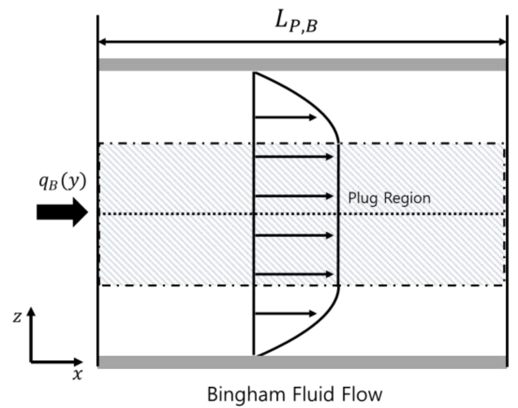
In this work, the bypass orifice consisting of three rectangular ducts operated with the flow mode is considered. All three rectangular ducts are analyzed by one rectangular duct model because they have the same dimension and are affected by the same magnitude of the magnetic field intensity. In this case, the orifice has just Bingham fluid flow as shown in Figure 12. In the same way as the main orifice, the pressure drop in the bypass orifice Δ P B is expressed as follows.
p y L p , B = Δ P B
In the above, the subscript B denotes bypass orifice. To achieve approximate solution, the non-dimensional parameter Φ B is defined as follows.
Φ B = p y p c = Δ P B L p , B   p c
Then, from Equation (8), the following solution is obtained.
Φ B = Ν B + 1.035 + Ν B 2 Ν B + 0.4
In case of the bypass orifice, there is no pole shape function and hence the flow rate per length is constant by Q B b B . From the definition of Ν B , the flow rate in the bypass orifice is obtained by:
Q B = b B h B 2 τ y , B 6 η Ν B
With Equations (27), (28), and (29), the relationship between the flow rate Q B and the pressure drop in the bypass orifice Δ P B can be obtained as follows [32].
Δ P B = 12 η b B h B 3 Q B L P , B + ( 2.07 + 12 η Q B 12 η Q B + 0.4 h B 2 τ y , B ) τ y , B h B L P , B

3.4. Total Flow through the Orifices

So far, the behaviors in each flow path have been independently analyzed. However, there are several flow modes depending on the magnitude of the magnetic intensity in the main orifice and bypass orifice. The main orifice has a closed, partially open, and fully open case. And the bypass orifice has close and fully open case. So, there are six different flow cases that can occur in MRD-PSF. However, because the change from partially open to fully open in the main orifice occurs continuously, there are ultimately four modes as shown in Table 1. There are three critical pressure drop values determining the modes, where Δ P c , M 1 is the pressure drop for the partially opening of the main orifice, Δ P c , M 2 is the pressure drop for the fully opening of the main orifice, and Δ P c , B is the pressure for the opening of the bypass orifice. These are given by:
Δ P c , M 1 = 2.07 · 2 τ y , M x m h M
Δ P c , M 2 = 2.07 · 2 τ y , M L p , m a x h M
Δ P c , B = 2.07 · τ y , B L P , B h B
Furthermore, based on the equation of continuity, the constitutive equation between total pressure drop and total flow rate can be obtained as follows.
Q t o t a l = Q M + Q B
Δ P t o t a l = Δ P M = Δ P B

4. Damping Force Characteristics

Total damping force of the proposed MRD-PSF is generated by the pressure difference between top and bottom chambers. If the damper is in a quasi-static motion and mechanical friction is neglected, it is calculated as follows.
F t o t a l = P 1 A p P 2 ( A p A r ) = Δ P A p + P 2 A r
P 1 = P 2 + Δ P ,     P 2 = P a + Δ P a P a
where, P 1 is the pressure of the upper chamber, P 2 is the pressure of the lower chamber, A p is the area of the piston, A r is the area of the piston rod and P a is the pressure of the air chamber. Total damping force is composed of damping force and air spring force.
F t o t a l = F d + F a i r   where : F d = Δ P · A p , F a i r = P a A r
Among many operation flow modes in Table 1, Mode 1 and Mode 2 are suitable to the proposed MRD-PSF in the sense of the operating principle described in Section 2. When the stroke velocity is low, only the main orifice is opened to realize high damping coefficient (Mode 1) and the bypass orifice is opened at the breaking point to provide low damping coefficient (Mode 2). In this case, damping force at the breaking point is Δ p C , B · A p . To evaluate the damping characteristic of the proposed damper, computer simulations are conducted. The design parameters used in the simulation are shown in Table 2. These parameters are chosen by considering the level of the damping force required for a middle-sized vehicle suspension system. The weight of the proposed MRD-PSF is 2.9 kg and the required electrical power with maximum operating current 1A, resistance of Coil 2 (5.4 Ω) and resistance of Coil 1 (2.1 Ω) is less than 10 W.

4.1. Damping Coefficient Control

As mentioned in Section 2, the damping coefficient change can be achieved by changing the effective orifice area of the main orifice before the SBP. The damping coefficient control is realized through the input current applied to the main orifice control part I M as shown in Figure 13. At this time, the current applied to the bypass orifice control part I B is set to 2A so that the bypass orifice is initially closed. It is seen that the damping force is degressively increased before the SBP. This is because the damping coefficient can be controlled critically when the main orifice is partially open with the closed bypass orifice. After the main orifice is fully opened, the degree of damping coefficient change is reduced. When I B is 2A, the point (damping force) where the bypass orifice is open is evaluated by 1326 N. Here, in order to evaluate the linear damping characteristics, the equivalent damping coefficient is defined as the linear gradient up to the SBP. When are 3, 2, 1, and 0 A, the equivalent damping coefficients are evaluated by 10,763, 8220, 4688, and 2295 Ns / m , respectively. And it is seen that the noticeable change in the damping coefficient occurs before the SBP. In additional, this tendency depends on the pole shape function. On the other hand, the damping coefficient is almost constant after the SBP. This is because the effective area of the bypass orifice is significantly larger than the effective area of the main orifice.

4.2. Position Control of the SBP

The SBP is determined whether the bypass orifice is opened or closed. The SBP change depending on the current applied to the bypass orifice control part I B is shown in Figure 14. At this time, the current applied in main orifice control part I M is set to 3 A so that it makes the effect of main orifice constant. When I B are 2, 1.5, 1, and 0.5 A, the point (damping force) where the bypass orifice is open is evaluated by 1326, 1063, 736, and 369 N. It is observed that the dramatic change in the damping coefficient occurs before and after these points. It is also seen that the stroke velocity at the SBP increases as the current applied to the bypass orifice I B increases.

4.3. Desired Damping Force Characteristics

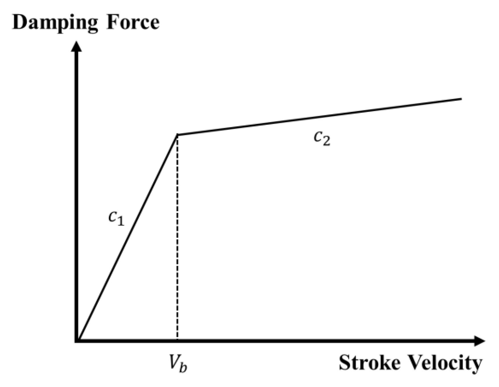
The damping characteristics of the passive damper and the proposed MRD-PSF can be regarded as bilinear damping characteristics. Figure 15 shows the bilinear damping characteristic. There are essential two parameters: c 1 is high damping coefficient before the SBP and c 2 is low damping coefficient after the SBP. In the figure, V b is the stroke velocity at the SBP. The characteristic of the proposed MRD-PSF is dependent on c 1 and V b . 
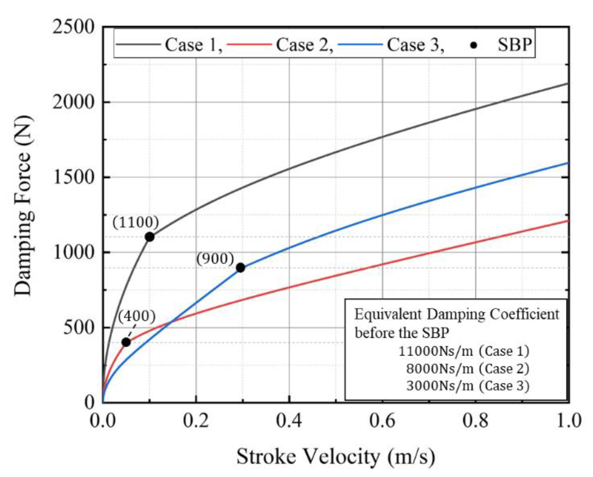
Table 3 shows the required input current in the main orifice and bypass orifice of I M ,   I B for implementing desired parameters c 1 and V b . Based on these parameters, the damping force characteristics of three different cases are determined as shown in Figure 16. c 1 and V b of Case 1 are 11,000 Ns / m and 0.1 m / s and desired input current I M and I B are 2.33 and 1.56 A. c 1 and V b of Case 2 are 8000 Ns / m and 0.05 m / s and desired input current I M and I B are 0.27 and 1.24 A. c 1 and V b of Case 3 are 3000 Ns / m and 0.3 m / s and desired input current I M and I B are 0.53 and 0.54 A. Therefore, it can be confirmed that the required bilinear damping characteristic in dynamic range can be achieved through two independent control variables. This is one of salient features of the proposed MRD-PSF.

5. Conclusions

In this work, a new type of MR damper having a specific pole shape function (MRD-PSF in short) was proposed and its effectiveness was demonstrated through computer simulations. After explaining the operating principle of the proposed damper with the schematic configuration, the field-dependent damping forces (or coefficients) characteristics are analyzed considering the main orifice and the bypass orifice. The activation of the main orifice can alter the magnitude of the damping coefficient, while the activation of the bypass orifice can change the position of the SBP. Subsequently, a certain desired damping force imposed in a wide stroke (or piston velocity) range can be realized by controlling input currents to be applied to the main orifice and bypass orifice, respectively. In other words, the bilinear damping characteristics required in real operation of vehicle suspension systems to achieve high ride comfort and steering stability can be realized by activating two independent parameters of the main orifice and bypass orifice in the open-loop control manner.
It is finally remarked that to validate the modelling and simulation shown in this work, the prototype fabrication of the MRD-PSF is ongoing. Its damping force characterization will be empirically evaluated and its application to the vehicle suspension system will be carried out in the future. In addition, control performance of a vehicle suspension system equipped with the proposed MR damper is to be carried out in the future to enhance both ride comfort and road holding property.

Author Contributions

Conceptualization, D.-S.Y. and B.-G.K.; methodology, B.-G.K, software, A.S.T., writing-review and editing, G.-W.K. and T.S., supervision, S.-B.C. All authors have read and agreed to the published version of the manuscript.

Funding

This research received no external funding.

Conflicts of Interest

The authors declare that they have no conflict of interest regarding the publication of this article.

References

  1. Fukushima, N.; Hidaka, K.; Iwata, K. Optimum characteristics of automotive shock absorbers under various driving conditions and road surfaces. Int. J. Veh. Des. 1983, 4, 463–472. [Google Scholar]
  2. Lacroix, B.; Seers, P.; Liu, Z. A Passive Nonlinear Damping Design for a Road Race Car Application; No. 2006-01-1984; SAE Technical Paper: Troy, MI, USA, 2006. [Google Scholar]
  3. Alleyne, A.; Hedrick, J.K. Nonlinear Control of a Quarter Car Active Suspension. In Proceedings of the 1992 American Control Conference, Chicago, IL, USA, 24–26 June 1992; pp. 21–25. [Google Scholar]
  4. Karnopp, D. Active Damping in Road Vehicle Suspension Systems. Veh. Syst. Dyn. 1983, 12, 291–311. [Google Scholar] [CrossRef]
  5. Thompson, A.G. An Active Suspension with Optimal Linear State Feedback. Veh. Syst. Dyn. 1976, 5, 187–203. [Google Scholar] [CrossRef]
  6. Sun, W.; Gao, H.; Kaynak, O. Finite Frequency H∞ Control for Vehicle Active Suspension Systems. IEEE Trans. Control Syst. Technol. 2010, 19, 416–422. [Google Scholar] [CrossRef]
  7. Li, H.; Yu, J.; Hilton, C.; Liu, H. Adaptive Sliding-Mode Control for Nonlinear Active Suspension Vehicle Systems Using T–S Fuzzy Approach. IEEE Trans. Ind. Electron. 2012, 60, 3328–3338. [Google Scholar] [CrossRef]
  8. Fialho, I.; Balas, G. Road adaptive active suspension design using linear parameter-varying gain-scheduling. IEEE Trans. Control Syst. Technol. 2002, 10, 43–54. [Google Scholar] [CrossRef] [Green Version]
  9. Yao, G.; Yap, F.; Chen, G.; Li, W.H.; Yeo, S. MR damper and its application for semi-active control of vehicle suspension system. Mechatronics 2002, 12, 963–973. [Google Scholar] [CrossRef] [Green Version]
  10. Hac, A.; Youn, I. Optimal Semi-Active Suspension with Preview based on a Quarter Car Model. In Proceedings of the 1991 American Control Conference, Boston, MA, USA, 26–28 June 1992. [Google Scholar]
  11. Nguyen, Q.-H.; Choi, S.-B. Optimal design of MR shock absorber and application to vehicle suspension. Smart Mater. Struct. 2009, 18, 035012. [Google Scholar] [CrossRef]
  12. Nguyen, Q.H.; Choi, S.-B. Optimal design of a vehicle magnetorheological damper considering the damping force and dynamic range. Smart Mater. Struct. 2008, 18, 015013. [Google Scholar] [CrossRef]
  13. Lu, S.-B.; Li, Y.-N.; Choi, S.-B.; Zheng, L.; Seong, M.-S. Integrated control on MR vehicle suspension system associated with braking and steering control. Veh. Syst. Dyn. 2011, 49, 361–380. [Google Scholar] [CrossRef]
  14. Choi, S.-B.; Han, S.-S. H∞ control of electrorheological suspension system subjected to parameter uncertainties. Mechatronics 2003, 13, 639–657. [Google Scholar] [CrossRef]
  15. Yu, M.; Choi, S.-B.; Dong, X.; Liao, C. Fuzzy Neural Network Control for Vehicle Stability Utilizing Magnetorheological Suspension System. J. Intell. Mater. Syst. Struct. 2009, 20, 457–466. [Google Scholar] [CrossRef]
  16. Sung, K.-G.; Han, Y.-M.; Sohn, J.W.; Choi, S.-B. Road test evaluation of vibration control performance of vehicle suspension featuring electrorheological shock absorbers. Proc. Inst. Mech. Eng. Part D J. Automob. Eng. 2008, 222, 685–698. [Google Scholar] [CrossRef]
  17. Choi, S.-B.; Han, Y.-M. MR seat suspension for vibration control of a commercial vehicle. Int. J. Veh. Des. 2003, 31, 202–215. [Google Scholar] [CrossRef]
  18. Choi, S.-B.; Gil Sung, K. Vibration control of magnetorheological damper system subjected to parameter variations. Int. J. Veh. Des. 2008, 46, 94–110. [Google Scholar] [CrossRef]
  19. Jeyasenthil, R.; Yoon, D.S.; Choi, S.-B.; Choi, S.-B. Response time effect of magnetorheological dampers in a semi-active vehicle suspension system: Performance assessment with quantitative feedback theory. Smart Mater. Struct. 2019, 28, 054001. [Google Scholar] [CrossRef]
  20. BWI Group. Available online: http://www.bwigroup.com (accessed on 6 January 2020).
  21. Carlson, J.D.; Jolly, M.R. MR fluid, foam and elastomer devices. Mechatronics 2000, 10, 555–569. [Google Scholar] [CrossRef]
  22. Olabi, A.; Grunwald, A. Design and application of magneto-rheological fluid. Mater. Des. 2007, 28, 2658–2664. [Google Scholar] [CrossRef] [Green Version]
  23. Goncalves, F.D.; Carlson, J.D. An alternate operation mode for MR fluids—Magnetic gradient pinch. J. Phys. Conf. Ser. 2009, 149, 12050. [Google Scholar] [CrossRef] [Green Version]
  24. Gołdasz, J.; Sapiński, B. Magnetostatic Analysis of a Pinch Mode Magnetorheological Valve. Acta Mech. Autom. 2017, 11, 229–232. [Google Scholar] [CrossRef] [Green Version]
  25. Goldasz, J.; Kluszczyński, K.; Sapinski, B. Fluid Flow Pinched by Near-Wall Bingham Plastic Zones: Simulation Study. In Proceedings of the 2018 19th International Conference on Research and Education in Mechatronics (REM), Delft, The Netherlands, 7–8 June 2018; pp. 48–51. [Google Scholar]
  26. Sohn, J.W.; Oh, J.-S.; Choi, S.-B. Design and novel type of a magnetorheological damper featuring piston bypass hole. Smart Mater. Struct. 2015, 24, 035013. [Google Scholar] [CrossRef]
  27. Lord Corp. MRF-132DG Data Sheet. Available online: https://www.lord.com/products-and-solutions/active-vibration-control/industrial-suspension-systems/magneto-rheological-mr-fluid (accessed on 26 June 2020).
  28. Phillips, R.W. Engineering Applications of Fluids with a Variable Yield Stress. Doctoral Dissertation, University of California, Berkeley, CA, USA, 1969. [Google Scholar]
  29. Gavin, H.P.; Hanson, R.D.; Filisko, F.E. Electrorheological Dampers, Part I: Analysis and Design. J. Appl. Mech. 1996, 63, 669–675. [Google Scholar] [CrossRef]
  30. Stanway, R.; Sproston, J.L.; El-Wahed, A.K. Applications of electro-rheological fluids in vibration control: A survey. Smart Mater. Struct. 1996, 5, 464–482. [Google Scholar] [CrossRef]
  31. Wereley, N.M.; Pang, L. Nondimensional analysis of semi-active electrorheological and magnetorheological dampers using approximate parallel plate models. Smart Mater. Struct. 1998, 7, 732–743. [Google Scholar] [CrossRef]
  32. Yang, G.; Spencer, B., Jr.; Carlson, J.; Sain, M. Large-scale MR fluid dampers: Modeling and dynamic performance considerations. Eng. Struct. 2002, 24, 309–323. [Google Scholar] [CrossRef]
Figure 1. Optimal damping characteristics of the passive damper.
Applsci 10 05586 g001
Figure 2. Damping force characteristics of magnetorheological (MR) damper: (a) conventional operation mode and (b) proposed mode with pole shape function.
Applsci 10 05586 g002
Figure 3. Configuration of the proposed MRD-PSF: (a) overall schematic; (b) core part; and (c) A A section view.
Applsci 10 05586 g003
Figure 4. Magnetic field analysis: (a) region and contour of the evaluated magnetic field; (b) Cross Section 1; (c) Cross Section 2; and (d) Line l l ' .
Applsci 10 05586 g004
Figure 5. Flow rate profile through the main orifice of MRD-PSF: (a) in low magnetic field and (b) in high magnetic field.
Applsci 10 05586 g005
Figure 6. Effective orifice area depending on the operating region: (a) the low stroke velocity and high damping coefficient and (b) the high stroke velocity and low damping coefficient.
Applsci 10 05586 g006
Figure 7. Magnetic field-dependent yield stress of MR fluid.
Applsci 10 05586 g007
Figure 8. Schematic configuration of parallel plate model and a coordinate system.
Applsci 10 05586 g008
Figure 9. Mean velocity profile of MR fluid in orifice.
Applsci 10 05586 g009
Figure 10. Mean velocity profile of MR fluid in the main orifice.
Applsci 10 05586 g010
Figure 11. Definition of pole shape function.
Applsci 10 05586 g011
Figure 12. Mean velocity profile of MR fluid in the bypass orifice.
Applsci 10 05586 g012
Figure 13. Damping force shaping by damping coefficient control.
Applsci 10 05586 g013
Figure 14. Damping force shaping by slope breaking point (SBP) control.
Applsci 10 05586 g014
Figure 15. Piecewise bilinear damping characteristic.
Applsci 10 05586 g015
Figure 16. Three examples of desired damping characteristics.
Applsci 10 05586 g016
Table 1. Several types of flow mode.
Main OrificeBypass OrificeConditions
Mode 1-1Partially openClose Δ P c , M 1 < Δ P < Δ P c , B
Mode 1-2Fully openClose Δ P c , M 2 < Δ P < Δ P c , B
Mode 2-1Partially openOpen Δ P c , B , Δ P c , M 1 < Δ P < Δ P c , M 2
Mode 2-2Fully openOpen Δ P c , B ,   Δ P c , M 2 < Δ P
Mode 3CloseOpen Δ P c , B < Δ P < Δ P c , M 1
Mode 4CloseClose Δ P < Δ P c , M 1 , Δ P c , B
Table 2. Design parameters of MRD-PSF.
ParameterSymbolValueUnit
Piston area A p 10.7521 × 10 4 m 2
Rod area A r 7.8540 × 10 5 m 2
Total orifice length of the main orifice L t , M 40 mm
Maximum effective pole length of the main orifice L p . m a x 10 mm
Minimum effective pole length of the main orifice x m 1 mm
Gap size of the main orifice h M 0.6 mm
Effective pole length of the bypass orifice L p , B 15 mm
Width of the bypass orifice b B 3 × 10 mm
Gap size of the bypass orifice h B 0.9 mm
Table 3. Required input current I M and I B for implementing some desired c 1 and V b .
Parameter
Type c 1 [Ns/m] V b [m/s] I M [A] I B [A]
Case 1110000.12.331.56
Case 280000.050.271.24
Case 330000.30.530.54

