Laser Metal Deposition of Ultra-Fine Duplex AlCrFe2Ni2-Based High-Entropy Alloy
 Veronica Rocio Molina
 Andreas Weisheit
 Sergej Gein
 Ulrike Hecht
 Dimitrios Vogiatzief
- 1Fraunhofer Institute for Laser Technology ILT, Aachen, Germany
- 2Access e.V., Aachen, Germany
- 3Oerlikon AM, Feldkirchen, Germany
A duplex, nano-scale Co-free high-entropy alloy (HEA) based on AlCrFe2Ni2 was processed using laser material deposition (LMD). Process parameters in various beam diameter configurations, as well as deposition strategies, were used while the alloy microstructure was investigated in the as-built and heat-treated condition. Interlayer regions present a duplex microstructure composed of ultra-fine face-centered cubic (FCC)-platelets nucleated in a nano-scale structured body-centered cubic (BCC) phase. Rapid cooling during LMD induces the decomposition of the BCC phase into ordered and disordered nano-scaled structures. The hard and brittle BCC phase yields a high crack susceptibility during rapid cooling in the LMD process. A suitable processing strategy paired with a post-processing heat treatment was developed to solve this challenge. After heat treatment at 900°C and 6 h annealing time with subsequent furnace cooling, the material presented a homogeneous duplex ultra-fine FCC/BCC microstructure and high bending strength (2310 MPa) compared to a heat-treated cast duplex-steel (1720 MPa) while maintaining excellent ductility (no failure at 20% bending strain).
Introduction
The concept of “high-entropy alloys (HEAs)” has been a breakthrough in the field of alloy development (Yeh et al., 2004). As opposed to conventional alloying of metals, this method exploits the high mixing entropy of multi-element compounds in equimolar or near-equimolar ratios, to avoid the formation of brittle intermetallic phases. Thus, various HEA-materials reportedly exhibit both high-strength and ductility as well as good corrosion and wear resistance in cast parts (Chuang et al., 2011; Shi et al., 2017; Chen et al., 2018; Niu et al., 2019). Consequently, these materials hold great potential for the fabrication of parts, such as pump impeller blades, subject to complex stresses (Ma et al., 2016; Yan-dong et al., 2017; Yin et al., 2017). Centrifugal and bending mixed stresses require a high strength material with sufficient ductility for this application. Besides, AlCrCoFeNi-based HEAs have been reported to perform exceptionally in terms of wear resistance, as well as simultaneous strength and ductility properties, which add to the interest toward this material for pump components (Lu et al., 2014; Gao et al., 2017; Shi et al., 2017).
In general, HEA alloy design presumes that a high number of principal elements in the compound – generally above three – will prompt the formation of solid solutions during solidification (Yeh et al., 2004). This presumption, however, relies on the rapid cooling of the melt to restrict diffusion and thus the growth of intermetallic compounds during solidification (Ocelík et al., 2016). Hence, laser-based additive manufacturing processes such as laser material deposition (LMD), in which cooling rates can reach up to 104 K/s, present an interesting prospect as a manufacturing method for HEAs. Various studies report LMD-processed HEA coatings of AlCrCoFeNi-based alloys, which have been found to yield fine-grained solid solution microstructures and allow a crack-free layer deposition (Kuwabara et al., 2018; Cui et al., 2019). Moreover, thin walls and small bulk volumes were fabricated using LMD, resulting in a fine-grained microstructure composed of body-centered cubic (BCC)- and B2 phases in as-built condition (Sistla et al., 2015; Joseph et al., 2017; Wang et al., 2017). Heat treatment trials above 800°C were reported to yield the formation of a softer face-centered cubic (FCC)-phase, reducing the reported brittleness and yield strength, while increasing ductility (Wang et al., 2017).
Despite the promising material properties, the use of cobalt (Co) may be ground for concern given that Co has been reported to carry a high monetary, environmental and human cost in its extraction and refinement (Crundwell et al., 2011). Borkar et al. (2017) performed comparisons between AlCoFeNi and AlCrFeNi alloys by compositionally graded samples produced via LMD. The systematic variation of the AlCoxCr1–xFeNi HEA composition shows the effect of Co on the microstructure evolution of the material. The presence of an intra-granular (spinoidal) decomposition of the BCC-Matrix into BCC/B2 was found for x = 0.2 and 0. Another Co-free HEA, namely AlCrFe2Ni2 was proposed by Dong et al. (2016), which presents a microstructure consisting of spinoidally decomposed B2/BCC-phase and an FCC-phase (Shang and Wang, 2017). The material presents a very interesting set of material properties, according to Dong et al. (2016) Cast AlCrFe2Ni2 was reported to achieve ultimate tensile strength (UTS) of 1228 MPa while withstanding 17% elongation during tensile testing. It was even suggested that these values exceeded those of titanium alloys in as-cast condition (Shang and Wang, 2017). Borkar et al. (2016) reported the fabrication of a Co-free HEA with composition AlxCrCuFeNi2 (0 < x < 1.5). An increase of the Al-content (x = 1.3 and 1.5, vs. 0) in the LMD fabricated HEA was reportedly linked to an increase in microhardness, indicating even higher material strength. In the present study, a near- AlCrFe2Ni2 alloy with a chemical composition of Al9Cr17Fe36Ni38 (wt.%) was selected for fabrication with LMD to examine the microstructure and material behavior in the as-built and heat-treated condition.
Materials and Methods
Two types of samples, named A and B accordingly, correspond to samples built using beam diameters of 0.6 and 1.8 mm, respectively. For a beam diameter of 0.6 mm (A samples), a Laserline LDM 3000-60 fiber-coupled diode laser system paired with a Sulzer Metco Twin 10-C powder feeder (Oerlikon AM) was used. For the 1.8 mm beam diameter configuration, (B samples), an LDF 2000-30 fiber-coupled diode laser and a GTV-PF2/2 powder feeder were employed. In all cases, the powder feeder systems implement argon gas as a protective and conveying medium toward a coaxial powder nozzle. Gas atomized powder with composition Al9Cr17Fe36Ni38 (wt.%), provided by Oerlikon AM was used in this study. A thorough investigation of the powder characteristics of the novel powder material was conducted to rule out powder related material defects. The powders’ particle size distribution was analyzed using a CAMSIZER® X2 system and corresponding software.
Hot-work, 10 mm thick 1.2343 (AISI H11) tool steel plates were used as base-plate material in all experiments. Pre-heating of the substrate plate was employed to reduce thermal gradient-related stress. This approach was conducted by placing the substrate material on an electrically heated hot-plate. The temperature was manually adjusted based on a temperature gauge placed on the plate surface. Pre-heating temperatures were set at room temperature (RT), 300 and 450°C for A samples and 450°C for B samples.
Laser material deposition process parameters such as scan speed, laser power, powder feed rate, track overlap, and layer thickness were determined to fabricate cubic bulk volumes with an edge length of 10 mm. For sample type “A” the laser beam diameter was 0.6 mm and for sample type B the laser beam diameter was 1.8 mm. The track overlap was set at 50 and 30%, respectively. The layer thickness employed corresponds to approximately 1/3 of the beam diameter in each case. The track deposition in all sample volumes was conducted in a bidirectional manner, i.e., adjoining tracks are deposited in both directions of a single axis sequentially. An overview of selected process parameter sets for LMD is summarized in Table 1 and a schematic diagram of the track deposition in a bulk volume is presented in Figure 1. Energy density E [J/mm3] calculations were performed as stated in Equation 1.
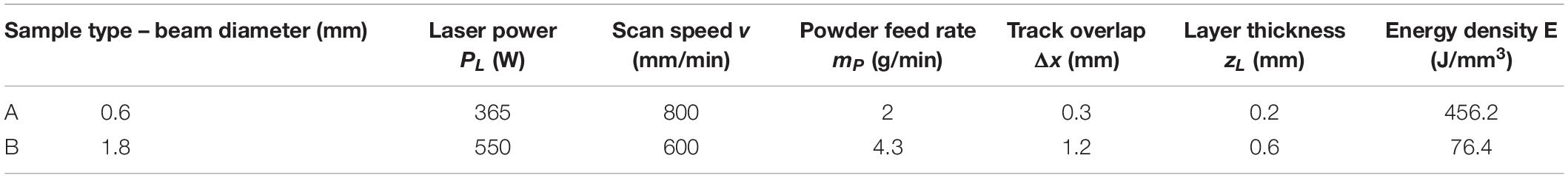
Table 1. Laser material deposition (LMD) process parameter sets for A- and B Sample production.
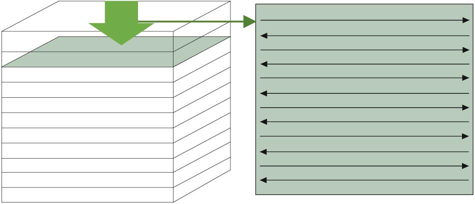
Figure 1. Schematic diagram of bidirectional track deposition pattern in laser material deposition (LMD).
Energy density calculation for LMD process:
The selection of a certain process parameter window strives toward crack-free build-up and a resulting porosity of max. 0.5%. Both quality characteristics were evaluated utilizing optical microscope analysis on sample cross-sections. The porosity-to-dense material-ratio is measured using “Stream Motion” software from the Olympus Group. Porosity measurements were performed through a gray-scale value analysis of pore vs. dense material surface ratio over the sample cross-section and extrapolated to the entire sample volume. Crack presence in the deposited material was also evaluated using optical microscopy. Crack propagation during metallographic preparation was ruled out by performing dye penetrant testing on selected samples before cutting.
Post-processing heat treatment of selected samples was carried out for microstructure homogenization and stress relaxation purposes for both A- and B- samples. This entails annealing at 900°C in an argon atmosphere for 6 h, followed by air cooling. Microstructure analyses were carried out with the support of Access e.V. with a Zeiss Ultra 55 scanning electron microscopy (SEM) system prior and after heat treatment. SEM analysis was only performed on samples fabricated with the final selected process parameter window for both sample types.
Studies of AlCrFe2Ni2 report a duplex BCC/FCC microstructure in cast samples and hardness values around 520 HV in vacuum hot pressing coatings of this HEA-material (Dong et al., 2016; Shang and Wang, 2017). In this study, a correspondence between the presence of FCC-phase in the microstructure and lower microhardness values was observed. Microhardness measurements according to Vickers DIN EN ISO 6507 were conducted for all fabricated samples at HV0.3 and 0.5 mm point-to-point distance along the build-height on the sample centerline using a Qness 30A microhardness tester and corresponding Qpix control software.
Additionally, B samples (x:y:z – 10:10:35 mm) were fabricated for a micro-scale three-point bending test before and after heat treatment. For this purpose, an MTI SEMtester 1000 was used. The samples were machined into flat tensile specimens (x:y:z – 10:10:35 mm) from one single LMD sample and bent at a traverse rate of 0.2 mm/min to the point of fraction or up to 20% elongation, which corresponds to the machines’ limit. A reference measurement, a DIN 1.4517 duplex steel was used as a reference frame for comparison.
Results
Powder Analysis
Powder analysis results of Al9Cr17Fe36Ni38 (wt.%) material are shown in Figure 2. The particle size distribution of a powder sample in terms of particle count (q0) and particle volume (q3) vs. particle equivalent diameter is shown in Figure 2A. For clarity purposes, the x-coordinate is transformed into a logarithmic scale. After logarithmic transformation, the variables are named q0∗ and q3∗ in Figure 2A, respectively.
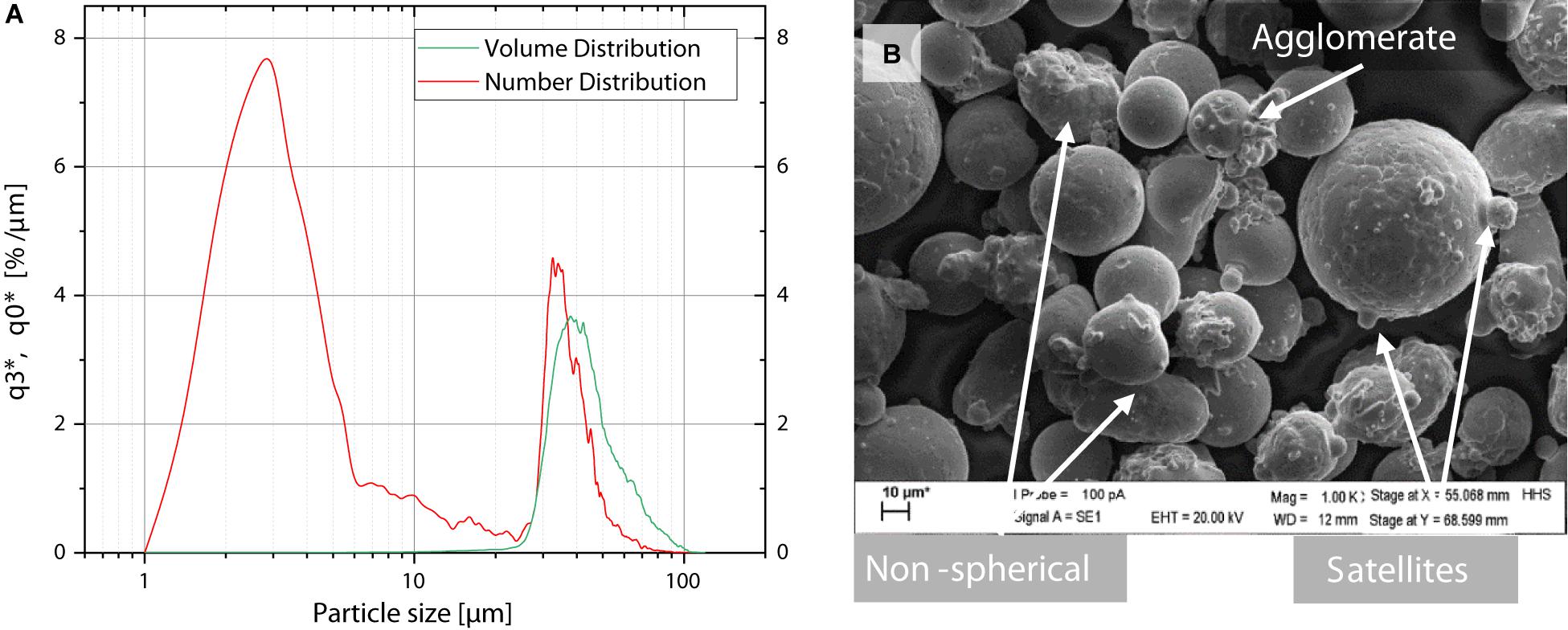
Figure 2. Powder analysis results of Al9Cr17Fe36Ni38 material in 20–90 μm fraction. (A) Particle size volume (q3) and number (q0) distribution curves scaled in (%/μm) vs. equivalent particle diameter (μm) showing one maximum in volume distribution and two maxima in number distribution, and (B) SEM image of powder material in 1000× magnification showing mainly spherical particles and some irregular shaped particles and satellites.
The volume distribution curve shows a single peak at 44 μm, corresponding to the 50-percentile value of the measurement. That is, roughly 50% of the powder should consist of particles larger than 44 μm in size. The 10-percentile was found at 34 μm and the 90-percentile at 69 μm in a volume distribution. However, the particle count or number distribution curve presents a different profile. A large peak is logged at 2.5 μm, which corresponds to the 10-percentile value. In this case, the 50-percentile is logged at 33 μm and 90-percentile at 47 μm. Hence, roughly 50% of the measured particles are smaller than 33 μm and only about 10% of the particles correspond to a size larger than 47 μm. Considering the nominal particle size range of 20–90 μm, a large number of fine particles are present in the powder material.
A high number of fine particles as well as non-spherical particles could lead to deficient flowability and consequently, inhomogeneous powder layer deposition during LMD. Using SEM micrographs, the powder material was further analyzed by visual examination as shown in Figure 2B. Fine particles are found predominantly in agglomerates and sintered to larger particles (satellites). The majority of observed particles present a spherical shape and no surface porosity.
Processability in LMD
The pre-heating temperature was found to have an impact on the inhibition of defect formation during the LMD processing of Al9Cr17Fe36Ni38 (wt.%). An overview of sample cross-sections highlighting arising material defects is presented in Figure 3. Large defect formation and cracking were found throughout all used pre-heating temperatures for A samples, namely RT, 300°C, and 450°C. At RT and 300°C surface plate temperature (Figures 3A,B), bonding defects between the substrate and deposited material, as well as at interlayers were observed in the evaluated cross-sections. At 450°C, lack of fusion was not observed in the analyzed material, but inhibition of crack formation was not achieved (Figure 3C). Moreover, optical microscopy imagery shows the formation of cavities, from which some of the cracks originate. Cavities and cracks are detected exclusively toward the sample outer walls.
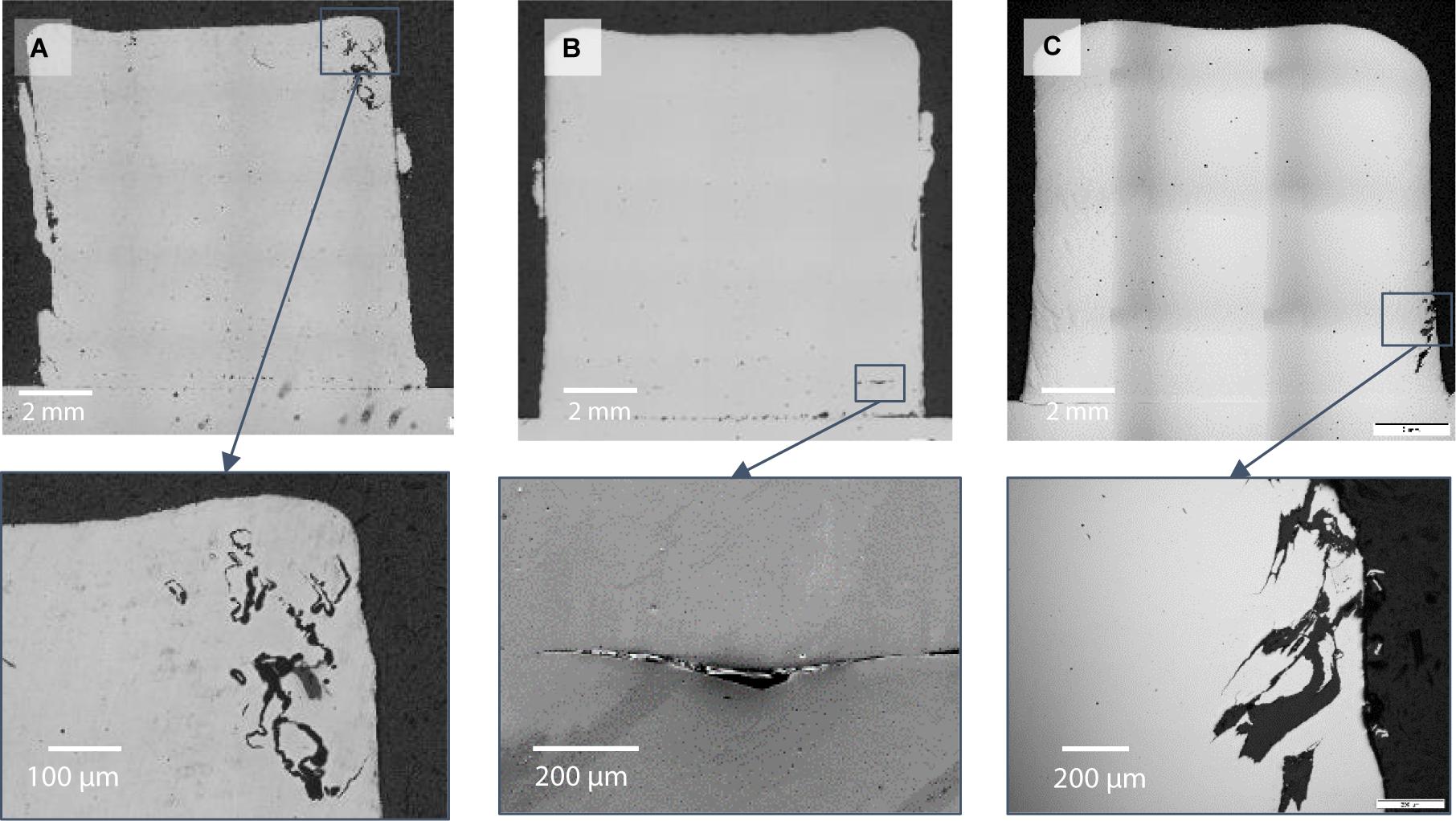
Figure 3. Sample cross-sections of A samples with different pre-heating temperatures on the surface plate during build-up. Respectively at room temperature (RT; (A)), 300°C (B), and 450°C (C), including relevant material defects in each case.
The defects visible in Figures 3A,C were found similar to reported micro-shrinkage defects in steel casting samples (Ghassemali et al., 2018). As reported by Ghassemali et al. (2018), micro shrinkage defects in the studied steel cast sample occur mainly at the cast “hot-spot,” specifically at grain boundary junctions of the present FCC phase in the steel material. The temperature gradients in the cast influence the shrinkage formation in the hottest areas. This phenomenon can also be applied to the present study. Due to the bidirectional track deposition used in this study, the dwell time of the laser radiation is higher at the track tails (beginning and end) than toward the middle of the track. This induces a higher temperature level at the bulk volume walls and thus, a higher temperature gradient between the deposited material and its surroundings. The examination of phase composition in the shrinkage area was not performed at this time.
The effect of the beam diameter size was evaluated by increasing the beam size to 1.8 mm (B Samples, see Table 1). Two sample cross-sections of B samples, built at RT and 450°C pre-heating temperature, respectively, are presented in Figure 4. No lack of fusion or bonding defects were found in B samples regardless of the pre-heating temperature. Samples built without pre-heating, or RT (Figure 4A), present distinctive crack formation along the sample build direction. Cracking seems to be inhibited using a pre-heating temperature of 450°C (Figure 4B). Similar crack formation along the build direction in LMD-produced samples has been reported for other materials, such as IN718 (Zhou et al., 2018). In that case, cracking was observed at track overlapping regions. A horizontal temperature gradient results from the overlapping of the molten material of a new track over a previously cooled-down neighboring track. The outcome of this is a high-angle boundary, which results in crack formation along its contour. This behavior may apply to the present study, given that cracks formation is inhibited through a higher pre-heating temperature and thus likely because of reduced temperature gradients within the bulk material.
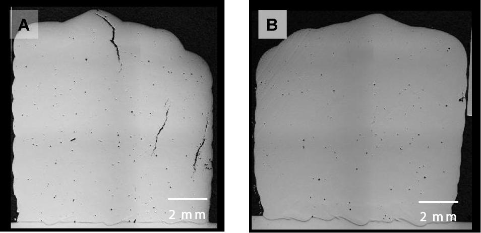
Figure 4. Micrograph images of sample cross-sections of B samples produced at room temperature (RT; (A)) and 450°C (B) pre-heating temperature showing cracks in build direction at RT and no cracks at 450°C.
Track length in LMD affects processability of the studied HEA alloy. Given a track length larger than 15 mm, produced (B-type) samples were found prone to crack formation, even at high pre-heating temperatures. Horizontally fabricated samples, with 10:10 mm (x:y) cross-section and a length of 35 mm presented cracking. Meanwhile, vertically fabricated samples, that is, samples with a 35:10 mm cross-section and a 10 mm length, were crack-free. Sample cross-sections of said results are presented in Figures 5A–E. All depicted samples were produced using pre-heating temperatures of 450°C and the B sample parameter set (see Table 1). It was found that, if the chosen track length was equal or smaller than 15 mm (Figures 5A,B), crack formation was inhibited during LMD-processing. Samples built otherwise equal, but using a track length of 35 mm, presented crack formation in build direction (Figures 5C,D). The sample height has no significant effect on crack formation. A micrograph image of a B sample fabricated under “standard” conditions, with 450°C pre-heating temperature and 10 mm long tracks built up to 35 mm sample height is presented in Figure 5E. There is a correlation between track length and the elapsed time between “passes” of the laser beam over the surface between the deposition of successive tracks. Longer tracks bring about a longer cooling period of the deposited material before a new track or layer is deposited. Consequently, a larger temperature difference within the cold and molten material is induced, and this results in crack formation in the overlap region between the two tracks in build direction. Shorter tracks and a fast sequence of re-melting allow heat retention inside the sample, reducing temperature gradients in the bulk material during processing.
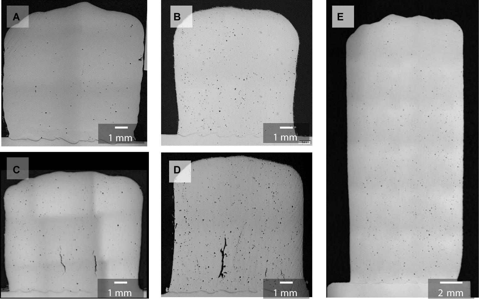
Figure 5. Sample cross-sections of B samples produced with 450°C pre-heating temperature and different track lengths and sample height. 10:10 mm cross-section samples with 15 mm track length (A,B) and 35 mm track length (C,D) as opposed to 35:10 mm cross-section and 10 mm track length (E). Cracks occur for the longer track length.
In samples manufactured with long tracks, as seen in Figures 5C,D, the crack formation is more frequent in the lower region of the sample, in the vicinity of the substrate plate. Due to relatively poor heat conductivity of the alloy in comparison to the substrate steel, the cooling rate in the in the lower layers is higher than that in the upper region of the samples. This assumption is supported by the observed outward curvature of the sample outline toward the sample top (Figures 5A–C). Given that the number of tracks is identical along the build direction, a bulging in the upper layers of the sample could indicate a larger melt pool during processing and hence, a higher temperature during deposition of the top layers.
Microstructure
As-Built
As proposed by Dong et al. (2016), the AlCrFe2Ni2 alloy consists of a duplex microstructure formed by an FCC phase, a disordered BCC (A2) phase, and an ordered BCC (B2) phase. The FCC phases were reportedly found as noodle-like structures, while the BCC (A2) phases were found as a precipitate-like structure, combined with inter-precipitate BCC (B2) phases. Borkar et al. (2017) reported elongated grain structures and a pronounced spinoidal decomposition of the BCC (B2) phase on LMD-fabricated AlCrFeNi. In this study, a microstructure with similar visual characteristics to those reported by Dong et al. (2016) and Borkar et al. (2017) was observed. Three SEM micrographs in increasing magnification of the interlayer region in an A-type sample (see Table 1) built at 450°C pre-heating temperature, in the as-built condition are shown in Figure 6. The low magnification image (Figure 6A) shows elongated grains along the build direction of the layers and grain refinement in the interlayer region. Similar results have been reported in the literature for in additively manufactured HEAs (Ocelík et al., 2016; Cui et al., 2019). The interlayer region presents a fine-grained structure, and the presence of bright, small structures that do not appear inside the deposited layers (Figure 6A). As seen at higher magnification in Figure 6B, a platelet structured phase is homogeneously distributed in this region. Even higher magnification SEM micrographs in this region (Figure 6C) reveal the presence of a nano-scaled compositionally de-mixed matrix. Based on the literature about near-AlCrFe2Ni2 HEA compositions (Dong et al., 2016) and electron backscatter diffraction (EBSD) performed in heat-treated condition (see section “Heat-Treated”), the microstructure is composed of two phases: FCC and BCC. The bright platelet-structures in Figures 6B,C correspond to the FCC phase, while the darker-toned matrix corresponds to the parent BCC phase, which is compositionally de-mixed into an Ni, Al-rich ordered and Fe, Cr-rich disordered phase, as reported by Dong et al. (2016) for AlCrFe2Ni2. Phase fractions were not analyzed in the as-built condition, but only after heat treatment (see section “Heat-Treated”).
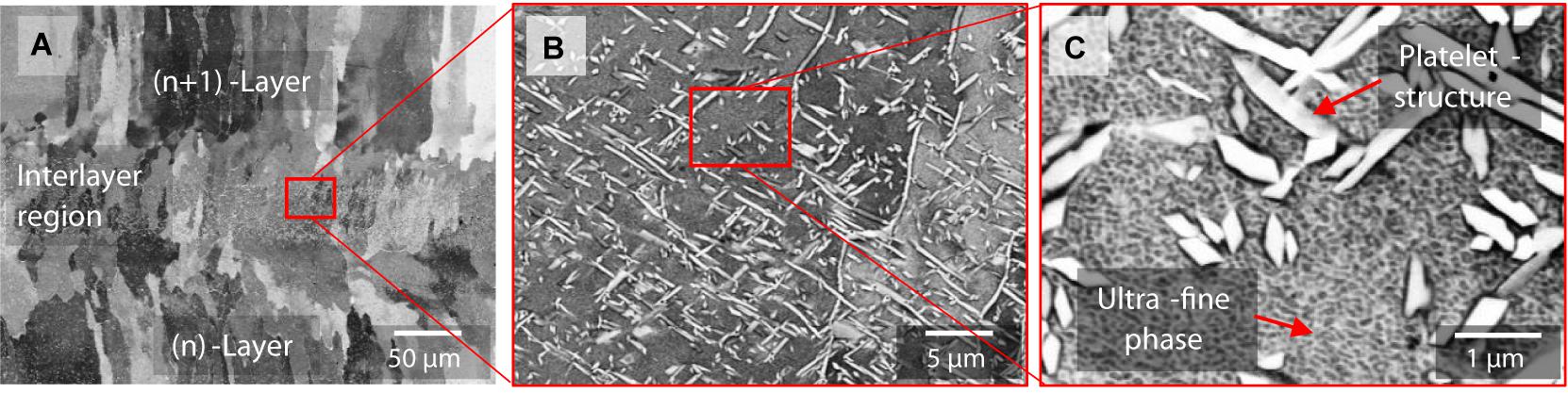
Figure 6. SEM images of laser material deposition (LMD) fabricated A sample (as-built) microstructure at interlayer region in 5000-× (A), 10000-× (B), and 20000-× (C) magnification. Homogeneously distributed platelet-structures are visible in the interlayer region only. The matrix is composed of two ultra-fine phases, seen at high magnification.
The presence of FCC-phase platelet structures in the interlayer region is due to the intrinsic heat treatment associated with the cyclic heat input during deposition of consecutive layers during LMD. That is, the BCC phase was found in a so-called metastable state in as-built condition, and an “intrinsic” heat-treatment of the material took place during the deposition of the new layer, which allowed the growth of FCC-platelets in the heat affected zone at the interlayer region. A similar microstructure behavior was suggested by Rahul et al. (2020) for a FeCoNiCuAl0.5 HEA during undercooling. High cooling rates in LMD potentially resemble undercooling in the studied conditions for the present HEA, as the solidification takes place at such high rates during processing. Thus the energy input necessary for a new layer deposition is sufficient for the growth of the FCC-phase inside the BCC matrix at boundaries between the two de-mixed BCC-phases.
An SEM image of a B sample in as-built condition (450°C pre-heating), taken just below the interlayer region is shown in Figure 7. Analog to A samples, an ultra-fine duplex microstructure and the presence of a bright phase and a darker, compositionally de-mixed matrix is observed. As proposed by Dong et al. (2016), the bright structures correspond to an FCC-phase, while the darker nano-scale compositionally de-mixed matrix corresponds to the decomposed BCC/B2-phases.
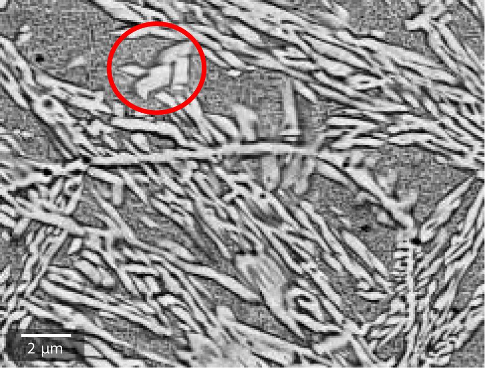
Figure 7. SEM image of laser material deposition (LMD) fabricated B sample with 450°C pre-heating at the vicinity of the interlayer region in as-built condition. FCC platelets (exemplified inside red circle) and Widmanstatten-like structures over a BCC/(B2) nano-scale compositionally de-mixed matrix are visible.
Relative to the studied A samples, a higher content of FCC is found in as-built B- samples, even inside the deposited layers, as seen in the SEM image in Figure 7. The FCC phase is observed in the form of small platelets (marked circle in Figure 7) as well as in longer, Widmanstatten-like structures throughout the studied region. The pronounced formation of the FCC phase within the sample microstructure is consistent with the theory of meta-stability of the BCC phase. Comparatively, the energy density during the processing of A samples is about six times higher than that of B samples, namely EB = 76.4 J/mm3 vs. EA = 456.2 J/mm3. As stated in Equation 1, the calculated energy density shows an inverse correlation with both the scan velocity and the beam diameter. Therefore, the formation of a higher content of the FCC phase in B samples compared to A samples can be attributed to two reasons: on one hand, the increased beam diameter has a larger impact area on the plane surface and a higher depth of penetration in the previously deposited layer, thus heating a larger volume of the sample. Secondly, the slower scan velocity results in a longer laser beam dwell time on the plane surface. These two effects overlap, allowing not only the formation of small FCC-platelets in the material but also the growth of the FCC phase within the material over a longer period.
Heat-Treated
After heat treatment at 900°C for 6 h, the resulting microstructure presents a homogeneously distributed duplex microstructure throughout the sample cross-sections. SEM images of heat treated A and B samples, including an EBSD phase analysis of an A sample are presented in Figure 8. The microstructure of the heat-treated A sample presents a homogeneous two-phase microstructure composed of larger, intertwined platelets over a homogeneous matrix (Figure 8A). According to the phase distribution analysis (Figure 8B), heat-treated A samples exhibit a duplex microstructure composed of 46% FCC-phase (bright, platelet structures) and 57% BCC-phase (dark, matrix). Heat-treated B samples present platelet-structures over a homogenous matrix, as seen in Figure 8C. Thus, heat treatment yields an equivalent structure of the FCC and BCC phases for both sample types A and B, as opposed to the previously observed differences in FCC-phase structures in as-built condition. After the applied heat treatment, the compositionally de-mixed matrix is no longer present in the analyzed microstructure in either sample type.
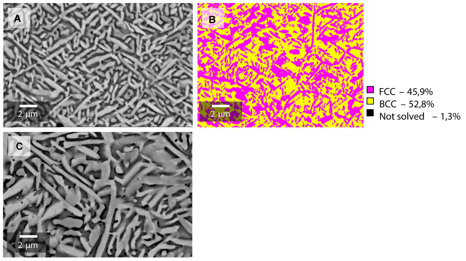
Figure 8. SEM images of laser material deposition (LMD) fabricated samples with 450°C pre-heating temperature. A samples (A) and B samples (C) after heat treatment at 900°C for 6 h, and an EBSD phase analysis of A sample microstructure after heat treatment (B). A duplex FCC/BCC microstructure is visible, and a 46%/53% (FCC/BCC) phase composition is determined.
Hardness
Hardness measurement profiles along the centerline of both an A sample and a B sample are shown in Figure 9, comparing as-built and heat-treated condition. Samples in as-built condition present an inhomogeneous hardness value distribution consistent with the findings in microstructure analyses. Measured hardness values fluctuate along the sample build direction. Moreover, for as-built condition, A samples show higher hardness values than B samples, namely 507 ± 37 HV0.3 vs. 386 ± 59 HV0.3. This leads to the conclusion that the observed higher FCC content in B samples (see section “Microstructure”) effectively leads to the increase of material ductility and reduction of strength. After heat treatment, the hardness profiles in both sample types show a homogeneous profile. Moreover, the hardness values of both sample types converge into a similar trend line at around 300 HV0.3. Again, this result correlates with the findings of microstructure analysis, which shows a very similar microstructure for both sample types after heat treatment, whereas A samples sustain a slightly higher hardness average than B samples, even after heat treatment.
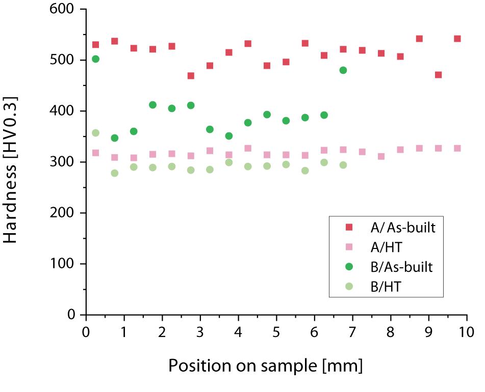
Figure 9. Hardness values along sample centerline for A and B samples in as-built and heat treated condition.
Bending Strength
The resulting stress vs. strain diagram from bending tests performed on selected samples is shown in Figure 10. Due to the high susceptibility to cracking in A samples, bending tests were only performed on B samples in this study. The presented diagram shows the test results for LMD samples fabricated in a vertical orientation build (x:y:z 10:10:35 mm) in both as-built (Vertical_As-Built) and heat-treated condition (Vertical_HT) and LMD samples in a horizontal orientation build (x:y:z 10:35:10 mm) in heat-treated condition (Horizontal_HT). A reference cast duplex-steel in heat-treated condition (Cast_DIN St.1.4517_HT) is depicted in the diagram as well.
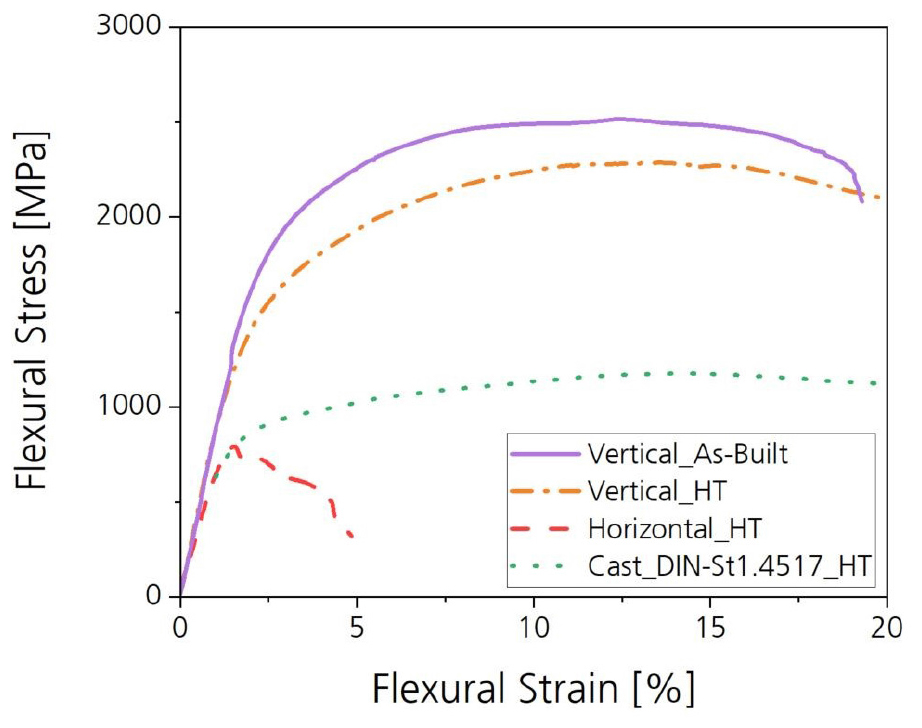
Figure 10. Bending test trendlines–stress (MPa) vs. strain (%) for laser material deposition fabricated B samples in as-built and heat-treated condition in a vertical build orientation (Vertical_As-Built, Vertical_HT), heat treated in a horizontal build orientation (Horizontal_HT), and a reference heat-treated DIN St.1.4517 cast sample material (Cast_DIN-St1.4517_HT).
In as-built condition, the LMD fabricated material exhibits a maximal bending strength of 2601 MPa and failure at 19.2% bending strain. This case is only depicted for the vertically built samples, since horizontally built samples presented premature failure during testing, which made bending testing impossible. After heat treatment, the maximal strength is achieved at 2286 MPa, and no failure behavior is observed up to the machine strain limit of 20% for vertically built samples. In comparison to the reference material, a strength increase of 50% is achieved by the studied HEA, while maintaining similar ductility.
Horizontally built samples reach the point of fracture at 4.5% bending strain even in heat-treated condition. Around 240 MPa and ∼0.2% strain, plastic deformation begins for the horizontally built, heat-treated LMD sample. This leads to the conclusion that inherent material defects propagate in the analyzed horizontally built B samples after this point. This material behavior correlates with the findings on material processability in LMD. Horizontally built samples present higher susceptibility to crack formation in build direction. Hence, lengthwise cut bending test samples will present transverse cracks, which cause failure at a low stress level.
Summary
An Al9Cr17Fe36Ni38 (wt.%) HEA was fabricated by means of LMD using two beam diameter sizes: 0.6 and 1.8 mm. The fabricated samples were evaluated in as-built and heat-treated condition regarding microstructure, hardness, and bending strength.
Processability
• Samples with dimensions 10 mm × 10 mm × 10 mm were fabricated successfully by LMD.
• Pre-heating of the substrate plate is necessary for crack-free fabrication. A temperature of 450°C of the base substrate plate was used to inhibit temperature-gradient-induced crack formation during processing.
• Using a 0.6 mm beam diameter, crack and shrinkage cavity formation in LMD-built samples were observed despite 450°C pre-heating.
• Using a 1.8 mm beam diameter, crack free samples of surface area 10 mm × 10 mm were successfully produced using LMD. Crack formation was observed when track lengths larger than 15 mm were used. A sample volume of 10:10:35 mm (x:y:z) was successfully fabricated using LMD and a 1.8 mm beam diameter producing crack-free samples with residual porosity <0.5%.
Microstructure
• In as-built condition, the material presents an inhomogeneous microstructure along the build height consistent with the layer-wise additive fabrication.
• Using a 0.6 mm beam diameter, the resulting microstructure in-layer presents elongated grains along the build direction and grain refinement in the interlayer region. The presence of homogeneously distributed platelet-like structures (FCC-phase) was observed only in the interlayer region. The presence of a nano-scale, compositionally de-mixed matrix (ordered/disordered BCC/B2 phases) was observed throughout the sample cross-section.
• Using a 1.8 mm beam diameter, an ultra-fine duplex microstructure was found throughout the sample. The microstructure is composed of an FCC phase in form of platelets and Widmanstatten-like structures and a compositionally de-mixed BCC matrix (ordered/disordered BCC/B2 phases).
• After heat treatment, a homogenization of the microstructure throughout the samples was observed in both 0.6 and 1.8 mm samples resulting in a duplex microstructure with a phase content of 46% vs. 53% for FCC/BCC-phases, respectively. The compositionally de-mixed matrix observed in as-built condition was no longer present after heat treatment. Samples built with a 1.8 mm beam diameter present coarser structures than 0.6 mm samples in heat-treated condition.
Mechanical Properties
• In as-built condition, all samples present an inhomogeneous hardness profile along build height. Hardness values reach 507 ± 37 HV0.3 for 0.6 mm beam diameter samples and 386 ± 59 HV0.3 for 1.8 mm beam diameter samples.
• After heat treatment, the hardness profiles of both sample types level-out at ∼300 HV.
• A three-point bending test was performed for samples built with a 1.8 mm beam diameter. A high strength/high ductility of the material using a vertical sample production (short tracks, high number of layers) was achieved. Using a horizontal sample production (long tracks, low number of layers), results in a low-ductility material.
• The maximal bending strength is achieved in a vertically produced 1.8 mm beam diameter sample in as-built condition, reaching 2601 MPa and failure at 19.2%.
• After heat treatment of the 1.8 mm beam diameter vertically built sample, the bending strength reaches 2286 MPa and no failure up to 20% bending strain (test machine limit). That is, the novel Al9Cr17Fe36Ni38 (wt.%) HEA produced my means of LMD presents, in heat-treated condition, an over 50% increase in strength compared to a DIN-St.1.4517 duplex steel, while maintaining similar ductility.
Data Availability Statement
The raw data supporting the conclusions of this article will be made available by the authors, without undue reservation.
Author Contributions
VM performed the process development in laser metal deposition as well as material analysis and result discussion. AW advised VM with material science and project development topics. UH provided with consulting support on the AlCrFeNi-HEA. SG performed a flexural test on LMD-produced material. DV and Oerlikon AM provided the novel HEA powder material used for the LMD process development. All authors contributed to the article and approved the submitted version.
Conflict of Interest
DV is employed by the company Oerlikon AM.
The remaining authors declare that the research was conducted in the absence of any commercial or financial relationships that could be construed as a potential conflict of interest.
Funding
The authors acknowledge the financial support by the Federal Ministry of Education and Research of Germany (Bundesministerium für Bildung und Forschung – BMBF) in the framework of the project NADEA (grant number 03XP0163B)1.
Footnotes
- ^ Das diesem Bericht zugrundeliegende Vorhaben wurde mit Mitteln des Bundesministeriums für Bildung und Forschung unter dem Förderkennzeichen 03XP0163B gefördert. Die Verantwortung für den Inhalt dieser Veröffentlichung liegt beim Autor.
References
Borkar, T., Chaudhary, V., Gwalani, B., Choudhuri, D., Mikler, C. V., Soni, V., et al. (2017). A combinatorial approach for assessing the magnetic properties of high entropy alloys: role of Cr in AlCo x Cr 1- x FeNi. Adv. Eng. Mater. 19:1700048. doi: 10.1002/adem.201700048
Borkar, T., Gwalani, B., Choudhuri, D., Mikler, C. V., Yannetta, C. J., Chen, X., et al. (2016). A combinatorial assessment of AlxCrCuFeNi2 (0 < x < 1.5) complex concentrated alloys: Microstructure, microhardness, and magnetic properties. Acta Mater. 116, 63–76. doi: 10.1016/j.actamat.2016.06.025
Chen, M., Shi, X. H., Yang, H., Liaw, P. K., Gao, M. C., Hawk, J. A., et al. (2018). Wear behavior of Al 0.6 CoCrFeNi high-entropy alloys: effect of environments. J. Mater. Res. 33, 3310–3320. doi: 10.1557/jmr.2018.279
Chuang, M.-H., Tsai, M.-H., Wang, W.-R., Lin, S.-J., and Yeh, J.-W. (2011). Microstructure and wear behavior of AlxCo1.5CrFeNi1.5Tiy high-entropy alloys. Acta Mater. 59, 6308–6317. doi: 10.1016/j.actamat.2011.06.041
Crundwell, F. K., Moats, M. S., Ramachandran, V., Robinson, T. G., and Davenport, W. G. (2011). “Cobalt – occurrence, production, use and price,” in Extractive Metallurgy of Nickel, Cobalt and Platinum Group Metals, eds F. Crundwell, M. Moats, V. Ramachandran, T. Robinson, and W. G. Davenport (Amsterdam: Elsevier), 357–363. doi: 10.1016/b978-0-08-096809-4.10028-0
Cui, W., Karnati, S., Zhang, X., Burns, E., and Liou, F. (2019). Fabrication of AlCoCrFeNi high-entropy alloy coating on an AISI 304 substrate via a CoFe2Ni intermediate layer. Entropy 21:2. doi: 10.3390/e21010002
Dong, Y., Gao, X., Lu, Y., Wang, T., and Li, T. (2016). A multi-component AlCrFe2Ni2 alloy with excellent mechanical properties. Mater. Lett. 169, 62–64. doi: 10.1016/j.matlet.2016.01.096
Gao, X., Lu, Y., Zhang, B., Liang, N., Wu, G., Sha, G., et al. (2017). Microstructural origins of high strength and high ductility in an AlCoCrFeNi2.1 eutectic high-entropy alloy. Acta Mater. 141, 59–66. doi: 10.1016/j.actamat.2017.07.041
Ghassemali, E., Jarfors, A., and Diószegi, A. (2018). On the formation of micro-shrinkage porosities in ductile iron cast components. Metals 8:551. doi: 10.3390/met8070551
Joseph, J., Stanford, N., Hodgson, P., and Fabijanic, D. M. (2017). Tension/compression asymmetry in additive manufactured face centered cubic high entropy alloy. Scripta Mater. 129, 30–34. doi: 10.1016/j.scriptamat.2016.10.023
Kuwabara, K., Shiratori, H., Fujieda, T., Yamanaka, K., Koizumi, Y., and Chiba, A. (2018). Mechanical and corrosion properties of AlCoCrFeNi high-entropy alloy fabricated with selective electron beam melting. Addit. Manufact. 23, 264–271. doi: 10.1016/j.addma.2018.06.006
Lu, Y., Dong, Y., Guo, S., Jiang, L., Kang, H., Wang, T., et al. (2014). A promising new class of high-temperature alloys: eutectic high-entropy alloys. Sci. Rep. 4:6200. doi: 10.1038/srep06200
Ma, X. D., Li, X. L., Zhu, Z. Q., Li, C. J., and Gao, S. (2016). The stress analysis of a heavy liquid metal pump impeller. IOP Conf. Ser.: Mater. Sci. Eng. 129:12023. doi: 10.1088/1757-899X/129/1/012023
Niu, P. D., Li, R. D., Yuan, T. C., Zhu, S. Y., Chen, C., Wang, M. B., et al. (2019). Microstructures and properties of an equimolar AlCoCrFeNi high entropy alloy printed by selective laser melting. Intermetallics 104, 24–32. doi: 10.1016/j.intermet.2018.10.018
Ocelík, V., Janssen, N., Smith, S. N., and de Hosson, J. T. M. (2016). Additive manufacturing of high-entropy alloys by laser processing. JOM 68, 1810–1818. doi: 10.1007/s11837-016-1888-z
Rahul, M. R., Samal, S., and Phanikumar, G. (2020). Metastable microstructures in the solidification of undercooled high entropy alloys. J. Alloys Comp. 821:153488. doi: 10.1016/j.jallcom.2019.153488
Shang, C. Y., and Wang, Y. (2017). AlCrFeNi high-entropy coating fabricated by mechanical alloying and hot pressing sintering. MSF 898, 628–637. doi: 10.4028/www.scientific.net/msf.898.628
Shi, Y., Yang, B., Xie, X., Brechtl, J., Dahmen, K. A., and Liaw, P. K. (2017). Corrosion of Al CoCrFeNi high-entropy alloys: al-content and potential scan-rate dependent pitting behavior. Corros. Sci. 119, 33–45. doi: 10.1016/j.corsci.2017.02.019
Sistla, H. R., Newkirk, J. W., and Frank Liou, F. (2015). Effect of Al/Ni ratio, heat treatment on phase transformations and microstructure of AlxFeCoCrNi2-x (x=0.3, 1) high entropy alloys. Mater. Design 81, 113–121. doi: 10.1016/j.matdes.2015.05.027
Wang, R., Zhang, K., Davies, C., and Wu, X. (2017). Evolution of microstructure, mechanical and corrosion properties of AlCoCrFeNi high-entropy alloy prepared by direct laser fabrication. J. Alloys Comp. 694, 971–981. doi: 10.1016/j.jallcom.2016.10.138
Yan-dong, G. U., and Shou-qi Yuan, Ji Pei, and Fan Meng. (2017). Numerical Analysis of Stress and Deformation of Impeller in the Mixed Flow Pump Based on Fluid-structure Interaction. Toronto, ON: DEStech.
Yeh, J.-W., Chen, S.-K., Lin, S.-J., Gan, J.-Y., Chin, T.-S., Shun, T.-T., et al. (2004). Nanostructured high-entropy alloys with multiple principal elements: novel alloy design concepts and outcomes. Adv. Eng. Mater. 6, 303–306. doi: 10.1002/adem.200300578
Yin, T., Pei, J., Yuan, S., Osman, M. K., Wang, J., and Wang, W. (2017). Fluid-structure interaction analysis of an impeller for a high-pressure booster pump for seawater desalination. J. Mech. Sci. Technol. 31, 5319–5328. doi: 10.1007/s12206-017-1026-z
Keywords: laser material deposition, high-entropy alloy, AlCrFeNi alloy, duplex microstructure, additive manufacturing
Citation: Molina VR, Weisheit A, Gein S, Hecht U and Vogiatzief D (2020) Laser Metal Deposition of Ultra-Fine Duplex AlCrFe2Ni2-Based High-Entropy Alloy. Front. Mater. 7:275. doi: 10.3389/fmats.2020.00275
Received: 31 May 2020; Accepted: 23 July 2020;
Published: 11 August 2020.
Edited by:
Antonio Caggiano, Darmstadt University of Technology, GermanyReviewed by:
Yiping Lu, Dalian University of Technology, ChinaBharat Gwalani, Pacific Northwest National Laboratory (DOE), United States
Copyright © 2020 Molina, Weisheit, Gein, Hecht and Vogiatzief. This is an open-access article distributed under the terms of the Creative Commons Attribution License (CC BY). The use, distribution or reproduction in other forums is permitted, provided the original author(s) and the copyright owner(s) are credited and that the original publication in this journal is cited, in accordance with accepted academic practice. No use, distribution or reproduction is permitted which does not comply with these terms.
*Correspondence: Veronica Rocio Molina, veronica.molina@ilt.fraunhofer.de