Electromagnetic Acoustic Detection of Steel Plate Defects Based on High-Energy Pulse Excitation


1
State Key Laboratory of Reliability and Intelligence of Electrical Equipment, Hebei University of Technology, Tianjin 300130, China
2
Key Laboratory of Electromagnetic Field and Electrical Apparatus Reliability of Hebei Province, Hebei University of Technology, Tianjin 300130, China
*
Author to whom correspondence should be addressed.
Appl. Sci. 2020, 10(16), 5534; https://doi.org/10.3390/app10165534
Submission received: 27 July 2020
/
Revised: 7 August 2020
/
Accepted: 7 August 2020
/
Published: 11 August 2020
(This article belongs to the Special Issue Nondestructive Testing (NDT): Volume II)
Abstract
:The conventional electromagnetic ultrasonic transducers (EMATs) rely on the static magnetic field created by magnets. The magnet increases the size of the EMATs, and the strong magnetic force of the magnet attracts the detected steel and even ferromagnetic particles. It can cause mechanical damage to the transducer and the detected objects. A new high-energy acoustic excitation system, without a static bias magnetic is designed, which does not include any magnets. As the core of the system, the high-energy pulse excitation power supplies a transient high voltage to the excitation coil by the LC oscillation circuit. The maximum amplitude of current can reach 1700 A, which is much larger than the current in the conventional EMATs. Compared with the conventional EMATs, the intensity of the ultrasonic signal is greatly strengthened and the size of the EMAT is effectively reduced. Therefore, it can detect high-temperature steel plates at a higher lift-off distance. In this paper, the transduction mechanism of high-energy pulse electromagnetic acoustic on ferromagnetic materials was studied, and the high-energy pulse excitation coil used for the A0 mode Lamb wave was designed. The interaction rule of the magnetic field, the force field, and the acoustic field, was obtained. Then, the EMAT lift-off characteristic experiment of the high-energy pulse excitation was carried out, and the defect detection experiment was conducted on a cracked steel plate. The results show that the A0 mode Lamb waves have caused a high signal-to-noise ratio and can accurately locate the crack, which has a great advantage in detecting the microcrack defects of ferromagnetic materials.
1. Introduction
Steel is an important material for the manufacture of products, such as precision machinery. It is easy to develop fractures caused by early fatigue damage and microcracks when exposed in harsh environments, such as high pressure, high temperature, and high speed for a long-term [1]. It threatens the safe operation of equipment and the safety of people’s lives. EMATs excite and receive acoustic waves through the electromagnetic coupling, and are widely used in the non-destructive testing field of metallic materials [2,3,4,5]. Compared with piezoelectric acoustic transducers, the detection efficiency is improved due to EMATs’ characteristics of non-contact and strong environmental adaptability. However, there are some problems in EMATs, such as low signal-to-noise ratio of received signals [6,7] and low transduction efficiency [8]. The signal is 20~40 dB lower than that of piezoelectric acoustic transducers [9]. In the detection of ferromagnetic materials, the magnet of EMATs generates a magnetic force to attract the steel, which brings inconvenience to the detection. Although the conventional EMATs do not contact the tested material directly, it is limited by the small lift-off distance. In addition, the detection requirements of the ferromagnetic material for the higher lift-off distance cannot be satisfied in extreme environments such as high temperatures.
In view of conversion efficiency and signal to noise ratio performance of EMATs, scholars have proposed some methods such as EMATs structure optimization [10,11,12,13,14]. In different metal materials, the main transduction mechanism of EMATs is different in generating ultrasonic waves. The Lorentz force is the main mechanism in non-ferromagnetic metal materials. However, in ferromagnetic materials, the Lorentz force, magnetizing force, and magnetostrictive force work together [15]. Compared with the Lorentz force and magnetostrictive force, the contribution of the magnetizing force is little in the generation of ultrasonic waves in steel materials and can be ignored [16]. Ogi found that the magnetostrictive force is affected by the direction and strength of the static bias magnetic field [17]. Ribichini proposed that the Lorentz force is the main mechanism of ferromagnetic materials in the normal bias field (vertical magnetic field) [18]. Ashigwuike found that when the external static magnetic field is a horizontal magnetic field, the main transduction mechanism of EMATs can be the magnetostrictive force [19]. In the horizontal magnetic field, Xu proved that the contribution of the low-carbon steel magnetostrictive mechanism for the EMATs efficiency increases with temperature increasing by simulation and experiment [20].
The existing research mainly focused on the optimization of the EMATs structure, whereas there is inadequate research in the improvement of the excitation power of EMATs.
Rueter established a simulation model of an electromagnetic acoustic excitation transducer without a bias magnetic field. The simulation and experiment results showed that acoustic waves can be effectively excited by high current in a circular coil [21,22]. A compact EMAT with a solid-state circuit and no permanent magnets was proposed by Rueter, which operates at MHz frequencies and detects through pulse echo detection method in narrow environments [23]. Tkocz demonstrated a new high-power phase-controlled EMAT that detected artificial internal defects of cast steel samples by a high amplitude superposition signal, composed of the signals excited by phased array coils [24]. A simple high-power EMAT without an external bias magnetic field was proposed by Rieger to detect defects of metal cans with liquid through the echo mode of longitudinal ultrasound [25]. Boni designed a multiple-rail acoustic excitation source with reproducible pulse power output and the switching noise is effectively reduced [26]. The high-power thyristor integrated circuit is generally used in conventional high-power pluse EMATs as an acoustic excitation source, such as a four-channel IGBT excitation source. Due to the shortcomings of thyristors, such as the thermal effects, low switching frequency, and low withstand voltage, the existing transducer can only excite low-frequency acoustic waves. Moreover, it is difficult to excite thousands of amperes of tone-burst excitation current in the electromagnetic acoustic excitation coil.
Above all, the transduction efficiency of conventional EMATs is low, especially at a higher lift-off distance. There is an upper limit in the bias magnetic field strength, which limits the maximum ultrasonic power, and ferromagnetic particles can be attracted by the magnets of conventional EMATs, the measurement results can be affected by which [27]. In order to solve the above problems, in this paper, a high-energy electromagnetic acoustic excitation system was designed without a static bias magnetic field, and a high-power LC oscillation circuit was used as an excitation source. A transient high voltage is applied to the excitation coil. Then a large current is generated in the coil to excite a dynamic strong magnetic field. The dynamic magnetic field interacts with the induced eddy current to generate a powerful electromagnetic force that can generate the acoustic wave. This method solves the problem that the excitation source power output is limited. The natural frequency of the LC oscillation circuit can be changed to achieve acoustic excitation in each frequency band, by simultaneously adjusting the LC circuit capacitance and the electrical parameters of the excitation coil. The magnetic field excited by the high-energy pulse coil in the eddy current layer of the tested material is horizontal. In order to study the main transduction mechanism, an EMAT lift-off characteristic experiment was carried out, and the relationship between the EMAT lift-off distance and the main action mechanism of ultrasonic waves was analyzed. The EMAT without permanent magnets avoids the effect of the bias magnetic fields, and Lamb waves are very sensitive to the change of the external and internal acoustic impedance of the propagation medium. The requirement for sensitivity is satisfied for the detection of the ferromagnetic material.
2. Electromagnetic Acoustic Excitation Transduction Mechanism of Ferromagnetic Materials Excited by the High-Energy Pulse
The three transductions mechanism of Lorentz force, magnetostrictive force, and magnetizing force exists simultaneously in ferromagnetic metal materials. The magnetostrictive force and the magnetizing force change nonlinearly with the applied magnetic field. Therefore, they were combined with the applied magnetic field during analysis. The Lorentz force transduction mechanism of ferromagnetic materials is consistent with non-ferromagnetic metal materials [16]. Due to the different electromagnetic parameters of materials, the magnitude of the Lorentz force is different. In metal materials, the Lorentz force is generated by the interaction between induced eddy current and applied dynamic magnetic field, and the induced pulsed eddy current field is expressed as,
where A is the magnetic vector potential, σ is the material conductivity, μ is the material permeability, and J is the current density in the coil.
The magnetic flux density B and induced pulse eddy Je meet:
In metal materials, the Lorenz force is expressed as,
where, FL is the Lorentz force in the metal material, Je is current density in the coil, B is dynamic magnetic flux density. There is no static bias magnetic field in the high-energy pulse EMAT. Lorentz force is generated by the interaction of dynamic magnetic field B and pulse eddy Je. The frequency of FL is twice the frequency of the current in the excitation coil, and the sensitivity of detection defects can be improved by the high-frequency acoustic signal [28].
The discharge circuit of the high-energy pulse electromagnetic acoustic excitation source can be simplified as a series connection of a discharge capacitor C, an excitation coil L, and an equivalent resistance R. The discharge process can be simplified to a LC second-order circuit zero input response.
The capacitor’s initial voltage uc and inductor current i are associated with reference direction. The characteristic equation of the circuit of high-energy pulse excitation source can be expressed as,
where L is the value of coil inductance, C is the value of capacitor capacitance, R is the circuit equivalent resistance, uc is the initial capacitor voltage, and s is the Laplace transform.
The requirement about the discharge circuit parameters of the high-energy pulse excitation source should be met, that R is much smaller than . In this way, the circuit operates in the zero-input underdamped state of the second-order circuit. The variation of current with time is a gradual decaying sinusoidal function relationship, in the discharge circuit. The Equations (5)–(7) combined to solve the current function relationship is Equation (8):
The represents the damping coefficient, and its value is proportional to the equivalent resistance in the circuit, which affects the rate of decay of current in the circuit.
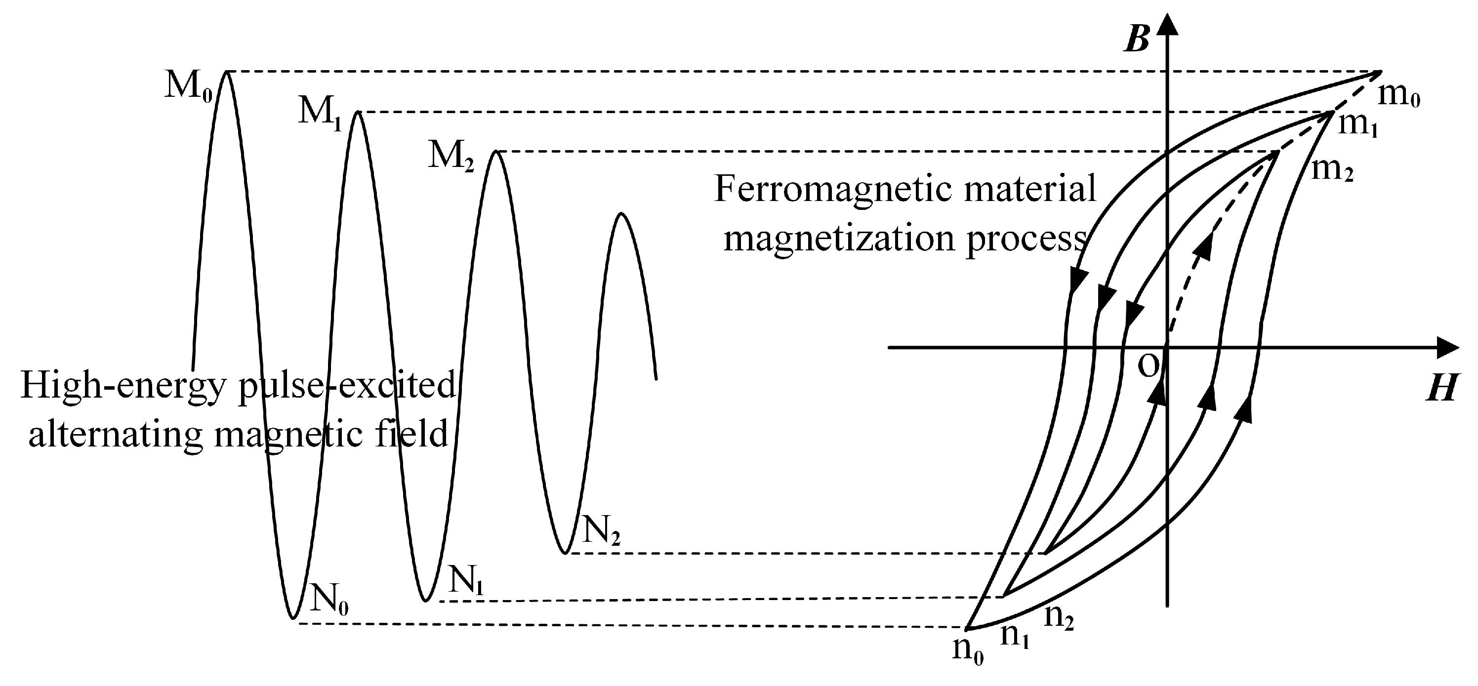
Due to the lack of a static bias magnetic field, hysteresis loops on the magnetization curve do not be formed in the magnetization process, but a cluster of hysteresis loops that decay to zero. The magnetization process is shown in Figure 1. The alternating magnetic field reaches the maximum M0 from zero, and the high-energy pulse electromagnetic acoustic magnetization changes along the magnetization curve O-m0. The magnetic flux density B increases with the magnetic field strength H to the maximum. The alternating magnetic field varies from a maximum value M0 to N0 and then to M1 in a decay cycle. The magnetic flux density B also varies in a period along m0-n0-m1 due to the hysteresis effect in ferromagnetic materials. In ferromagnetic materials, the magnetic flux density B decays periodically with the magnetic field strength H, and finally decays to zero.
Due to the action of the alternating magnetic field, acoustic waves are excited by the mechanical vibration which is caused by periodic stretching and compression of the material. The magnetizing force FM is generated by the alternating magnetic field, is shown in Equation (9),
where μ0 represents magnetic permeability in the vacuum, and M represents the magnetization vector.
In addition to the magnetic field affecting the magnetization of ferromagnetic materials, the EMAT conversion mechanism of ferromagnetic materials also adds a magnetostrictive conversion mechanism. For ferromagnetic materials, the magnetostrictive constitutive relationship can be expressed as,
where Gε is the strain matrix, Tσ is the stress tensor matrix, KμT is the reversible magnetic permeability matrix of the material, μ0 represents the vacuum magnetic permeability, H is the dynamic magnetic field strength, B is the magnetic induction intensity, DM is the piezoelectric magnetic matrix, Cc is the stiffness matrix, and NT is the inverse pressure magnetic matrix. The first equation in Equation (10) describes the magnetostrictive effect, which is the strain caused by the application of a magnetic field. The second equation describes the inverse magnetostrictive effect, which is the change in flux density detected by the sensor when the stress generates a change in flux. When an alternating magnetic field is applied to the ferromagnetic material, the tested material is magnetized and stressed, and the constitutive equation of the ferromagnetic material is corrected. Its magnetic field strength H and magnetostrictive force fM are satisfied:
The transduction mechanism in the excitation of high-energy pulse power can be expressed as:
The first part is the magnetizing force, the second part is the Lorentz force, and the third part is the magnetostrictive force. However, it can be ignored in most cases as the magnetizing force is relatively small.
3. Simulation Analysis of High-Energy Pulse EMAT
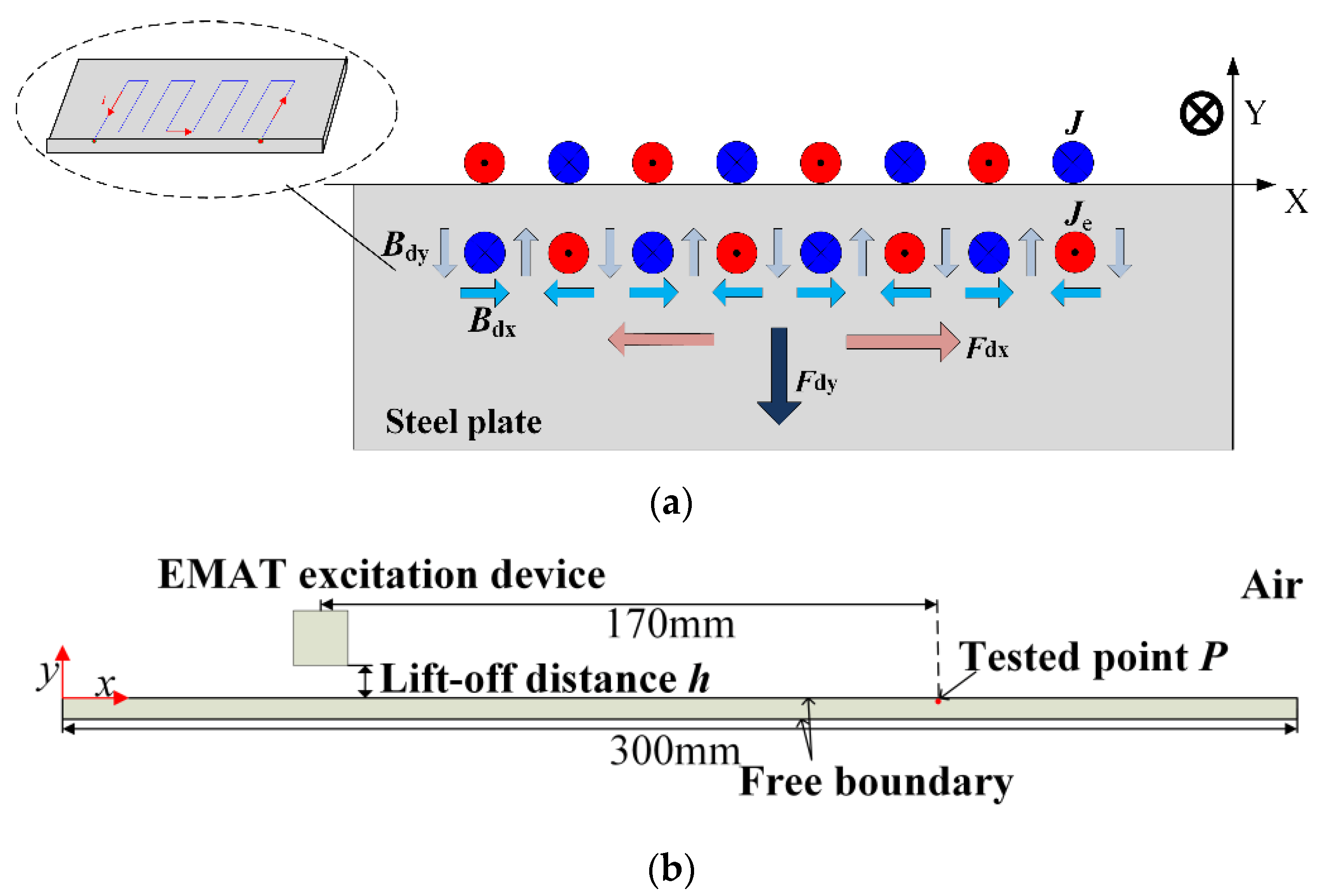
In this paper, COMSOL Multiphysics was used to establish a high-energy pulse EMAT model. The effects of Lorentz force, magnetostrictive force, electromagnetic force, and lift-off distance on the Lamb wave generated by high-energy pulse EMAT were simulated. Figure 2a is the schematic diagram of the high-energy pulse EMAT excitation acoustic wave, where Bdx and Bdy are the horizontal and vertical components of the dynamic magnetic field, and Fdx and Fdy are the horizontal and vertical components of the electromagnetic force. In the low-frequency band, S mode particle vibration is mainly in-plane displacement, whereas a mode vibration is mainly out-of-plane displacement. The finite element simulation model of high-energy pulse EMAT is shown in Figure 2b. The steel plate size is 300 mm × 1 mm, the starting coordinate of the left end of the excitation coil is (−63, 0.5), the point P to be measured is (107, −0.01), and the distance between the sending and receiving is 170 mm. In the high-energy pulse excitation coil, the current is obtained by the Equation (8), which is shown in Figure 3a. The spectrum analysis of the current is shown in Figure 3b. The coil line spacing should be designed as the line spacing corresponding to the frequency of about 220 kHz. The model parameters are shown in Table 1.
3.1. Characteristic of Magnetic Flux Density Distribution in High-Energy Pulse Excitation
In the condition that the lift-off distance h is 0 mm, the magnetic flux density distribution of the high-energy pulse EMAT in different directions was simulated and analyzed.
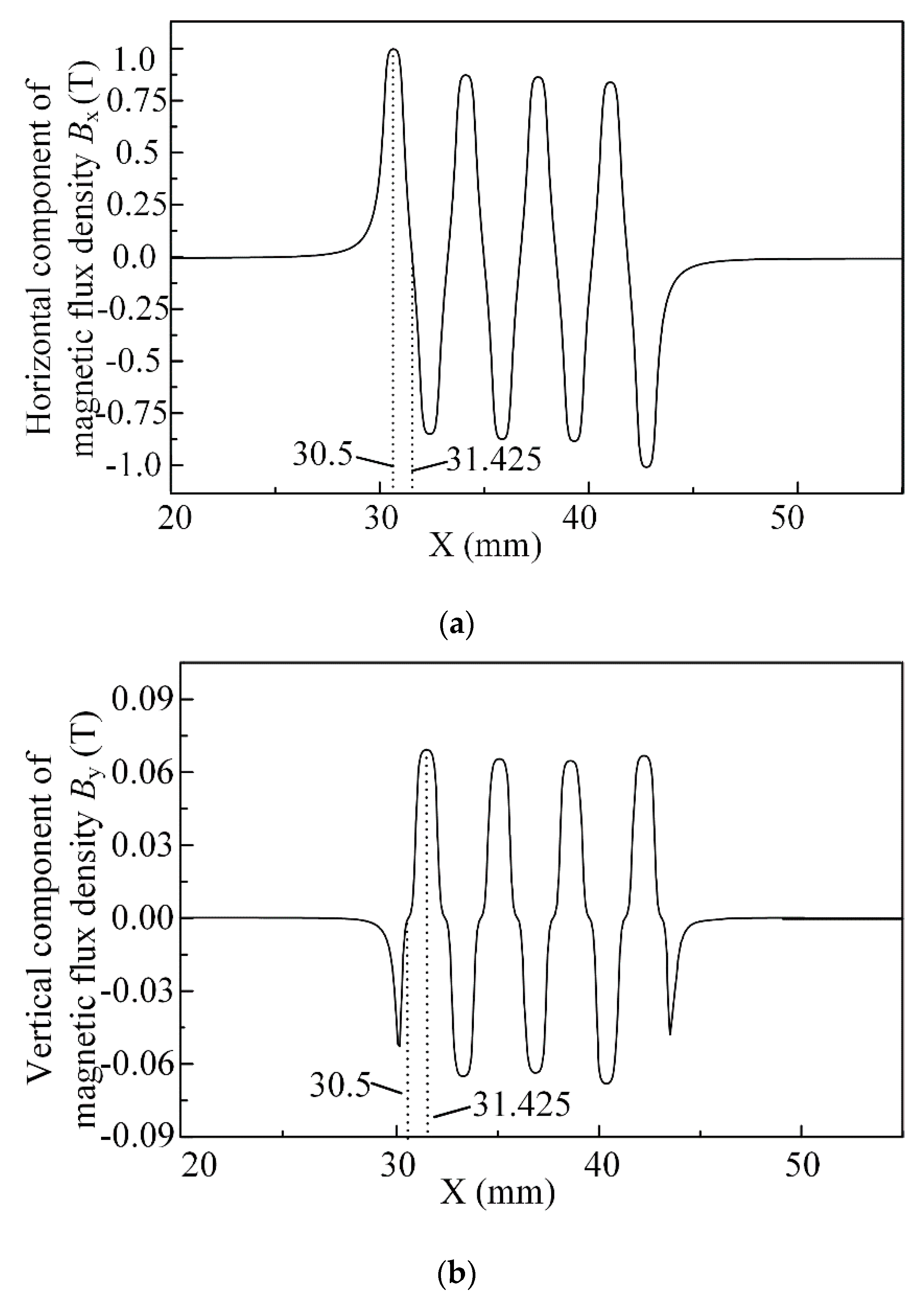
Figure 4a,b are the magnetic flux density distribution of the high-energy pulse EMAT in different directions (Bx is the horizontal component of magnetic flux density and By is the vertical component of magnetic flux density) of the steel plate surface. From Figure 4a, when the measured point is exactly below the axis of the excitation coil wire (such as x = 30.5), the amplitude corresponding to the horizontal component Bx of magnetic flux density is the highest. When the measured point is exactly under the middle of the two adjacent wires of the meander coil (such as x = 31.425), the value Bx is 0. From Figure 4b, the distribution of By is exactly the opposite to the distribution of Bx. In Figure 4b, the measured point exactly below the excitation coil wire axis (for example, x = 30.5) corresponds to 0. Whereas, in the position exactly below the middle of the two adjacent wires of the meander coil (for example, x = 31.425), the amplitude is the highest. Based on the comparison between Figure 4a,b, it can be seen that the magnetic flux density in the horizontal direction is larger than that in the vertical direction by an order of magnitude. In other words, the contribution of the magnetic flux density is mainly dominated by the horizontal component of magnetic flux density. According to the aforementioned, in ferromagnetic materials, only when the direction of the magnetic field is horizontal, the magnetostrictive force may become the main mechanism of action. It is critical to determine when the Lorentz force and magnetostrictive force is the main mechanism of transduction.
3.2. Influence of Lift-Off Distance on High-Energy Pulse EMAT Transduction Mechanism
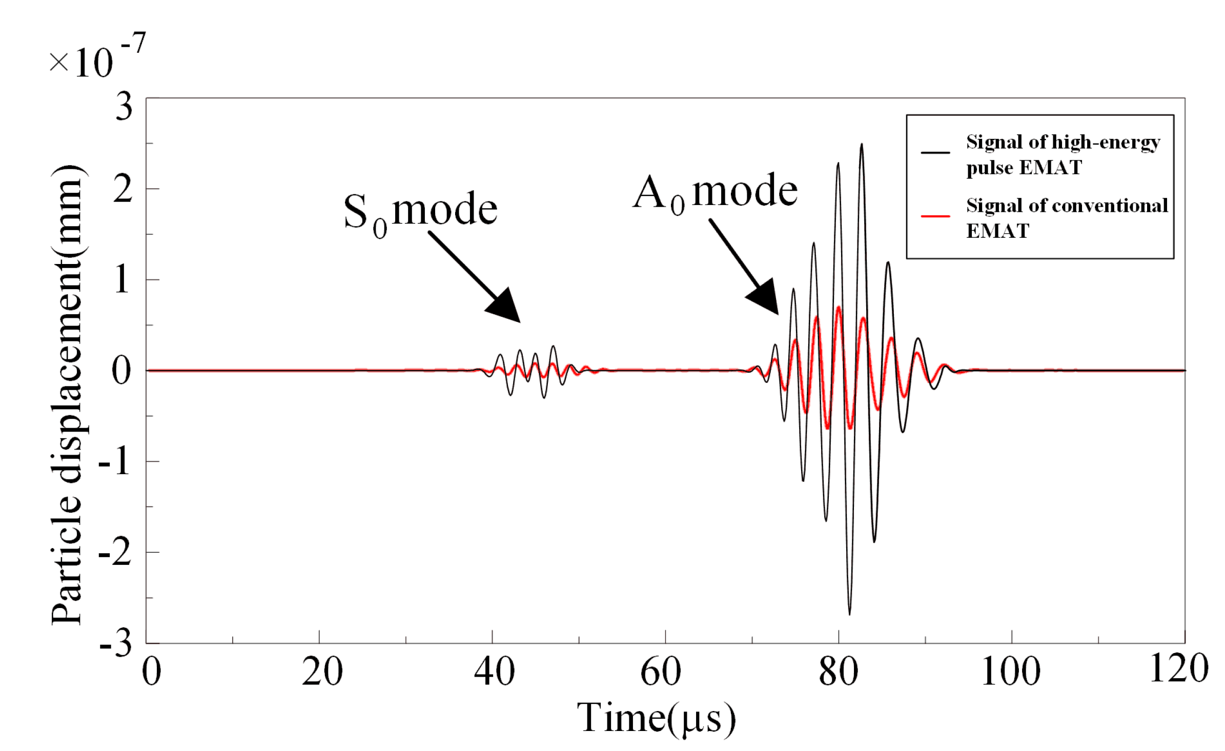
The simulations of the high energy pulse EMAT, and the conventional EMAT, were used for comparison to show the difference in amplitude and the two simulations used the same simulation settings. In the conventional EMAT simulation model, the residual magnetic flux density of the magnet is set to 1.2 T and the lift-off distance is 0 mm. At the distance h = 0 mm, the Lamb signals of the high-energy pulse EMAT and the conventional EMAT at point P is shown in Figure 5. The group velocity of S0 mode is faster than that of A0 mode, and S0 mode reaches P point first. The vibration amplitude of A0 mode is much larger than that of S0 mode. The time-domain signal amplitude of A0 mode in high-energy pulse EMAT is 3.2 times that of conventional EMAT. The S0 mode signal amplitude of the high-energy pulse EAMT is 2.9 times that of the conventional EMAT.
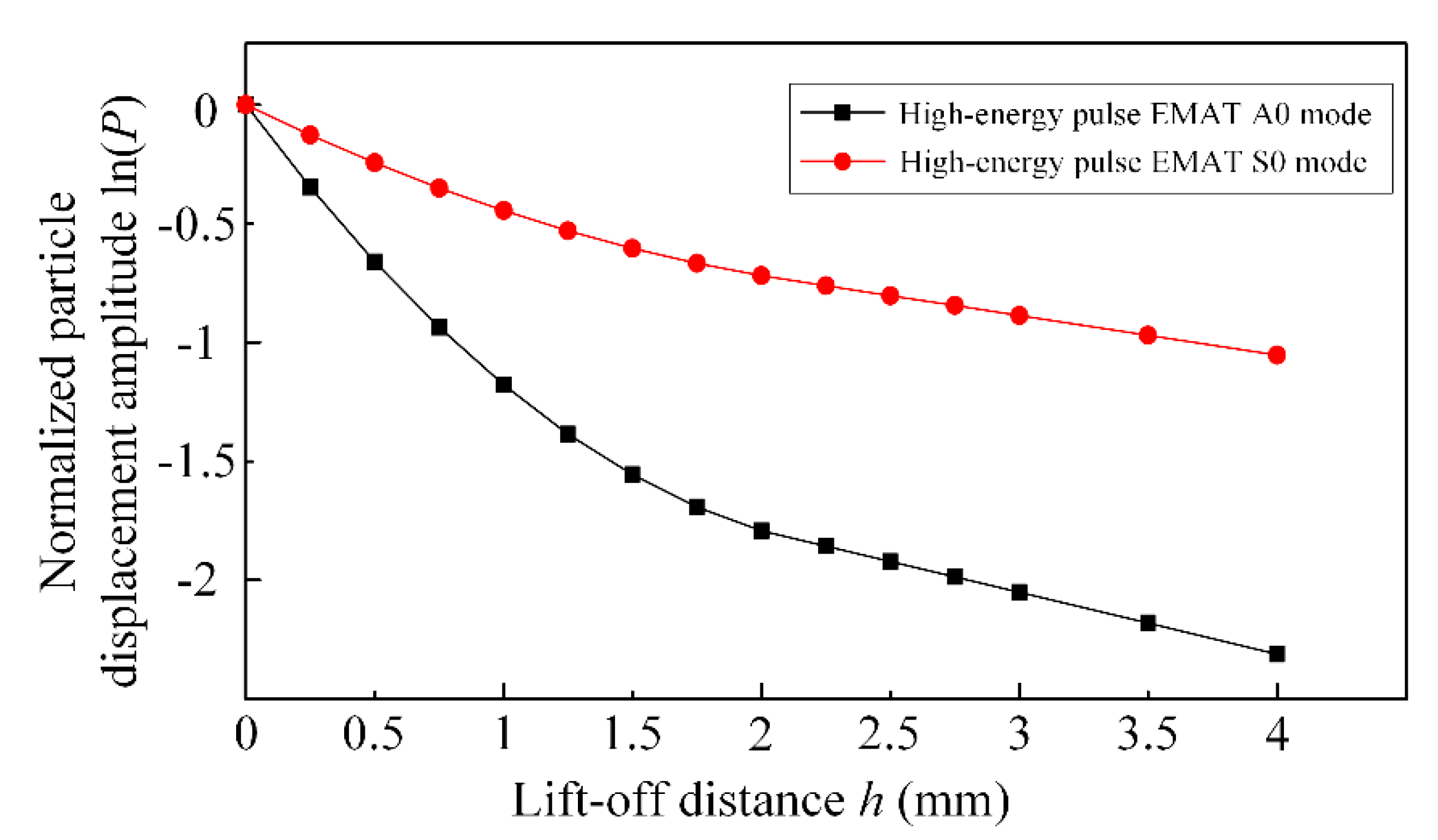
To facilitate the study of the attenuation of the particle displacements of S0 and A0 modes, the particle displacements of the S0 and A0 modes were extracted and analyzed. The change curve of displacement amplitude with lift-off distance is obtained, as shown in Figure 6.
The ultrasonic amplitude generally decreases with an exponential function as the lift-off distance increases, in non-ferromagnetic materials, such as aluminum plates. However, in ferromagnetic materials such as steel plates, the A0 and S0 modes in the Lamb waves excited by high-energy pulse EMAT do not decay exponentially, in the small lift-off distance. When the lift-off distance h is more than 2 mm, the S0 and A0 modes decay exponentially with the lift-off distance. So the displacement log ln(P) of the S0 and A0 modes vary approximately linearly with the lift-off distance h, as is shown in Figure 6. Due to the attenuation rate of the Lorentz force FL determined by B and Je is higher than the magnetostrictive force fM decided only by B. In this case, the energy conversion mechanism is mainly dominated by the magnetostrictive force fM in the steel plate. In the steel plate, the high-energy pulsed electromagnetic ultrasonic energy conversion mechanism is composed of the Lorentz force and magnetostrictive force, in the lift-off distance h less than 2 mm. In this lift-off distance section, the Lamb wave A0 and S0 modes do not decay with an exponential function as the lift-off distance increases.
4. Experimental Parameter Design
4.1. Overall Design of High-Energy Pulse Power Supply
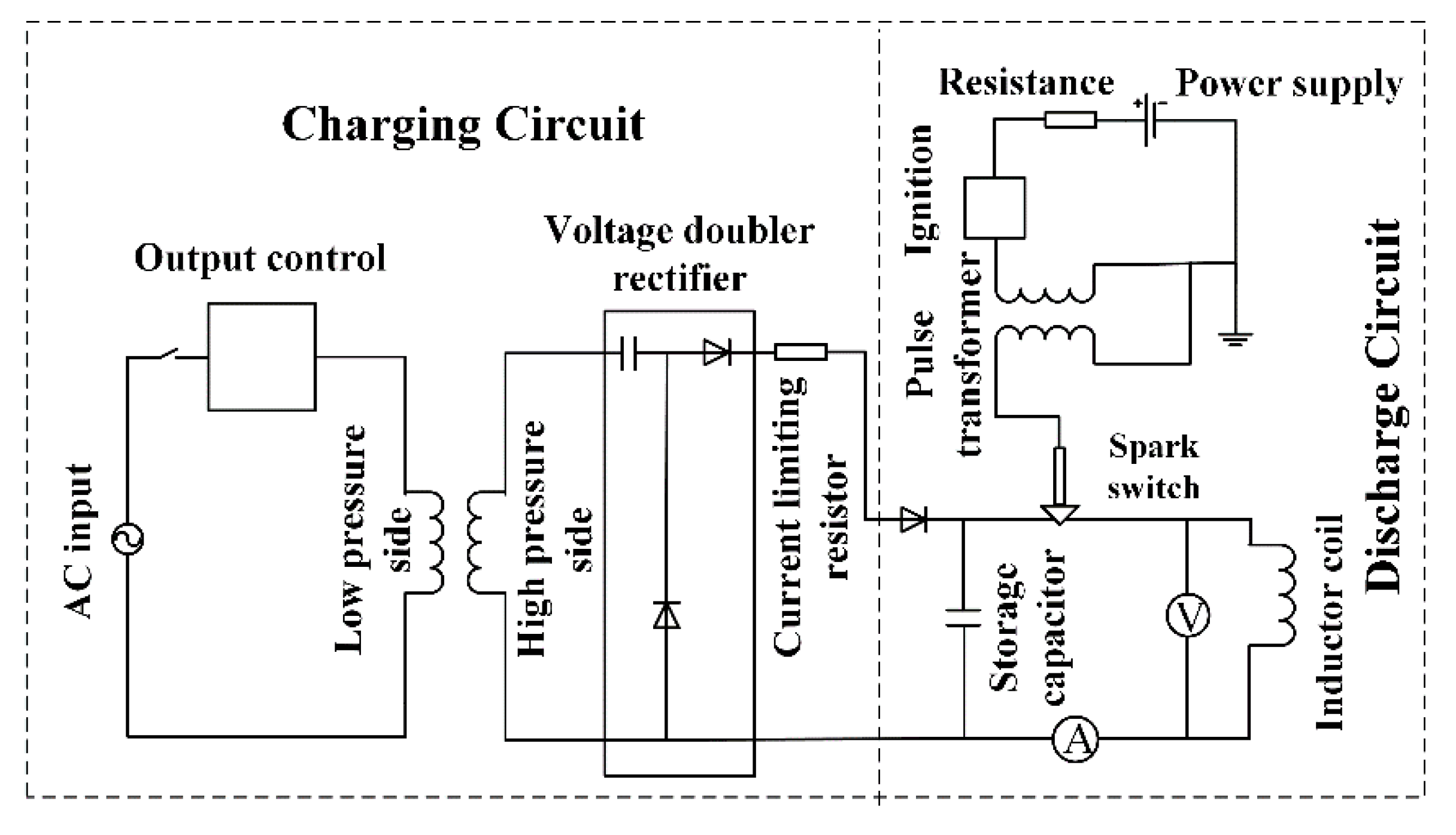
Based on pulse power technology, a high-power pulse power supply with adjustable current intensity and pulse frequency was developed, and a capacitor energy storage scheme was used. As shown in Figure 7, the pulse power source is mainly composed of a charging part consisting of a high-voltage DC power source and an energy storage capacitor group and a discharge part comprised of the energy storage capacitor group and an inductor coil used for discharging through the spark plug. The high-voltage DC power supply charges the storage capacitor. The high-voltage DC power supply charges the energy storage capacitor, and the circuit is disconnected when charging is completed. Then, the spark switch is closed to make the discharge circuit conduct, and a strong transient pulse current is generated in the excitation coil, which excites a dynamic magnetic field and induces eddy current on the metal surface. The interaction between the eddy current and the dynamic magnetic field excites an ultrasonic signal.
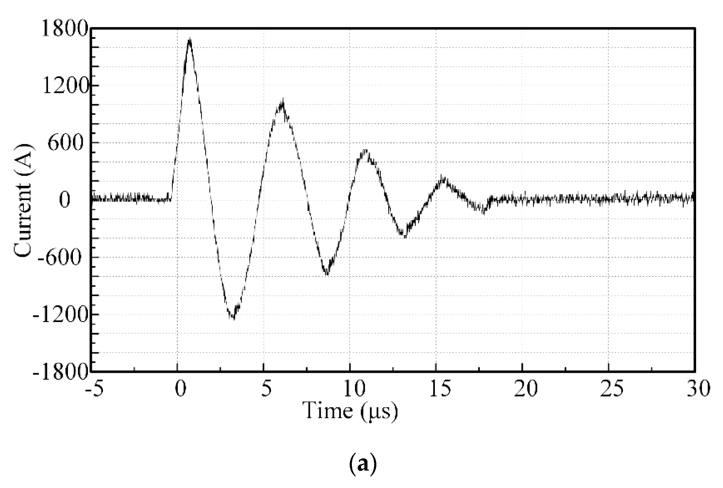
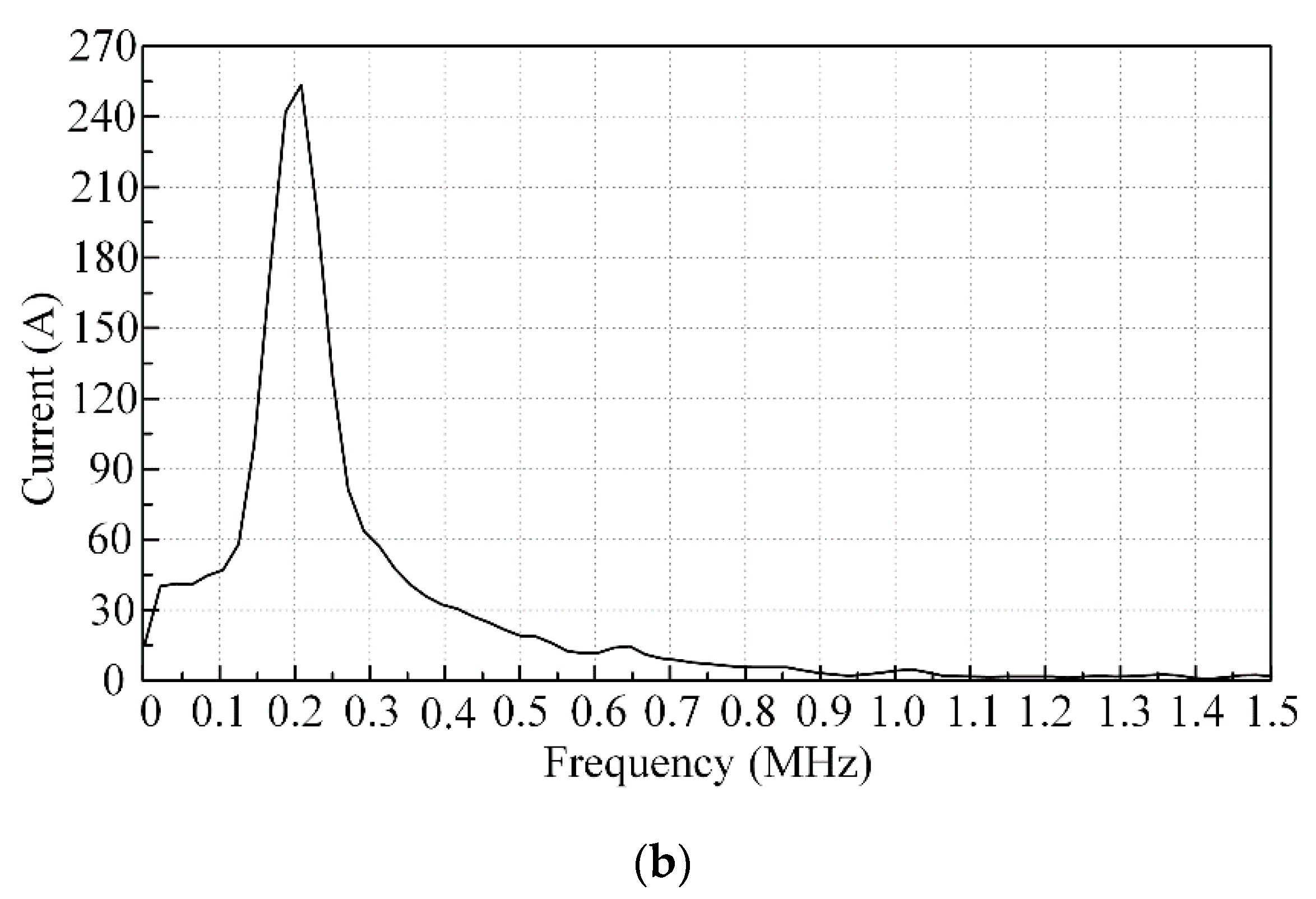
After the voltage is stepped down by the high voltage probe, which is connected to the oscilloscope to obtain the voltage signal across the known resistance, and then converted into a current signal. The time domain and frequency domain characteristics of the current signal are analyzed, as shown in Figure 8.
4.2. Coil Experimental Parameters
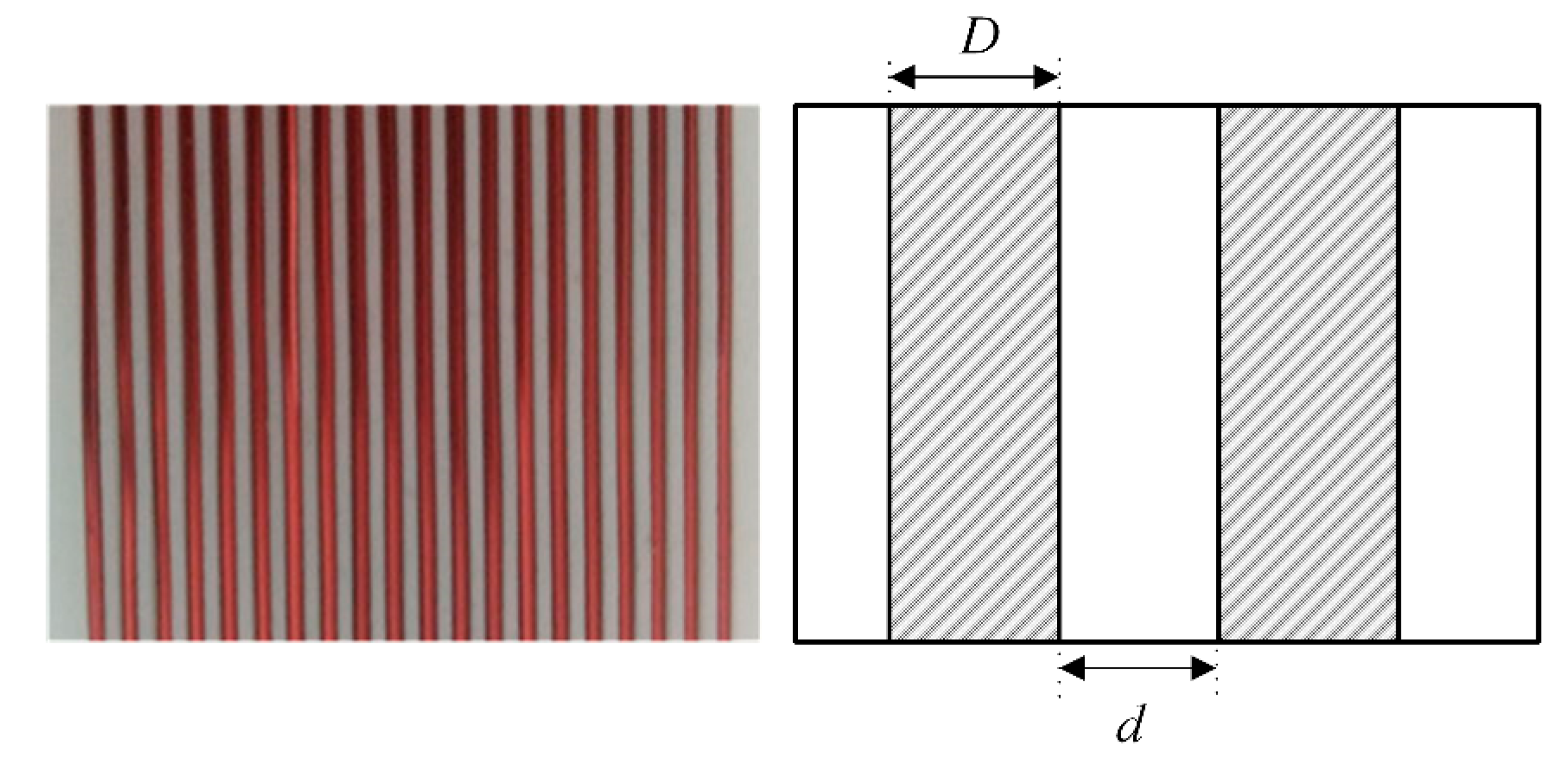
Meander coils of EMATs are generally used to excite Lamb waves. According to the coherent principle, the coil’s interval is designed for odd multiples of half the guided wavelength. The frequency of the current in the excitation coil is 220 kHz, and the frequency of the Lamb wave is 440 kHz in the steel. In the experiment, 1 mm thick Q235 steel plates were used as the detected material. According to the spectrum characteristic of Lamb, the lamb frequency thickness product of the 1 mm thick steel plate is 0.44 MHz·mm, and the phase velocity of the steel plate is 1.56 km/s. The enameled wire with a wire diameter D of 1 mm was used to make the coil, and the center-to-center spacing of the meander coil was designed to be 1.77 mm. Besides, the spacing d of the separator is 0.77 mm, as shown in Figure 9.
The current in the coil is a pulse impulse current, which is similar to short-circuit current. Therefore, the thermal and dynamic stabilities of the impact state need to be checked to verify its reliability. The purpose of thermal stability verification is to ensure that the coil will not be burned by the current thermal effect in a large current. The minimum cross-sectional area of the conductor determined by thermal stability is Smin:
Ch is the thermal stability coefficient. In this experiment, Ch is 186, Qk is the short-circuit current thermal effect, and Kf is the skin effect coefficient, which is 1.02.
From Figure 8a, the pulse current duration is 25 μs, the current amplitude is 1700 A. The RMS current is calculated to be 506 A, and the calculated short-circuit thermal effect Qk is 2.3409 A2·s. Therefore, Smin is 8.307 × 10⁻³ mm2. Whereas, the cross-sectional area of the copper wire with a radius of 0.5 mm is 0.785 mm2. It is much larger than the minimum cross-sectional area of the conductor’s thermal stability, so the thermal stability requirement is met.
The purpose of dynamic stability verification is to ensure that the coil structure will not be destroyed by the action of electromotive force in a large current. The limitation of the conductor’s mechanical properties is determined by the dynamic stability verification Equation (14):
The fph is the electromotive force on the conductor of unit length, L is the line spacing, and W is the interface coefficient of the conductor perpendicular to the direction of the force. In the experiment, 3D printing technology PVC material was used to make the skeleton, and the coil was embedded in it to fix. The withstand stress of PVC material can be up to 50 MPa, which is much greater than the theoretical calculated stress and pressure of the wire. Therefore, the structure meets the requirements of safety and reliability.
4.3. Design of Charging Circuit
The charging circuit of the high-energy pulse power supply consists of a voltage doubler rectifier circuit, an energy storage capacitor, and a protection circuit. The 220 V AC is converted into high voltage DC by the voltage doubler rectifier circuit. The protection circuit, composed of a current limiting resistor and a diode, is used to ensure the safety of the charging process. The dielectric capacitor with characters of high-frequency and high-voltage is used as an energy storage element. It stores the energy from the voltage doubler rectifier circuit and discharges energy to the inductor coil after the spark switch is on. The E62.C81-102E40 high-voltage power capacitor is selected as the energy storage capacitor. Its rated DC impulse voltage is 1700 V, and the capacitance value is 1 μF. The series equivalent resistance is 11.5 mΩ, and the dielectric loss tangent is 2 × 10⁻⁴. The dielectric loss tangent value is small, so the leakage loss can be ignored at high-energy pulse excitation operating frequency.
4.4. Spark Switch Trigger Pulse Timing
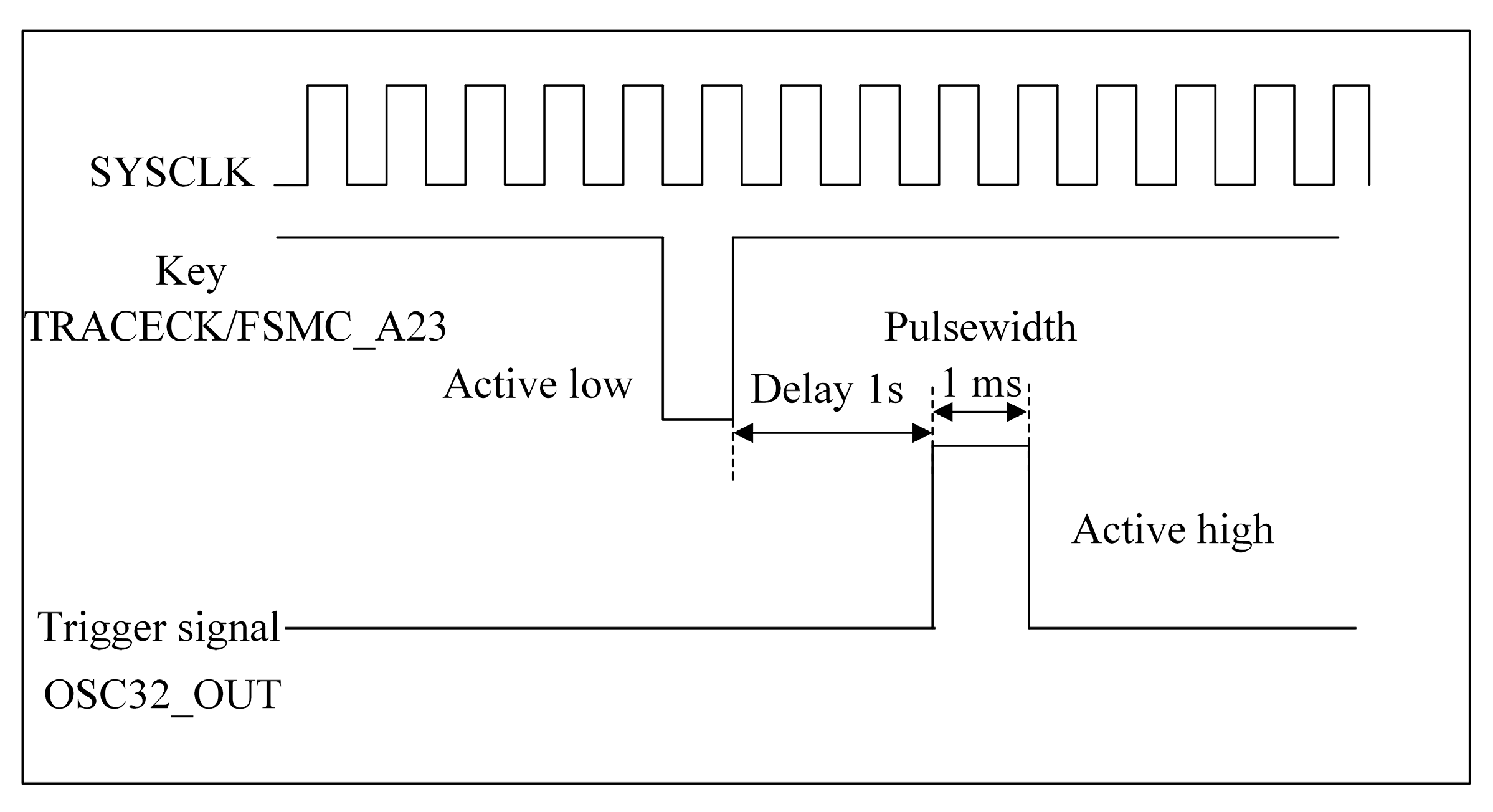
The trigger voltage is generated by a DC high-voltage generator with a maximum voltage of up to 35 kV. The di/dt ratio can ensure a good switching characteristic. The conduction time of the discharge circuit is controlled by an STM32 microcontroller PZ6806L. In order to turn on the spark switch, the trigger electrode is turned on with 1 ms to break through the air gap, after the start button is turned on for 1 s delay. The timing of the trigger pulse is shown in the Figure 10.
5. Experimental Analysis of Acoustic Propagation Characteristics about High-Energy Pulse Excitation
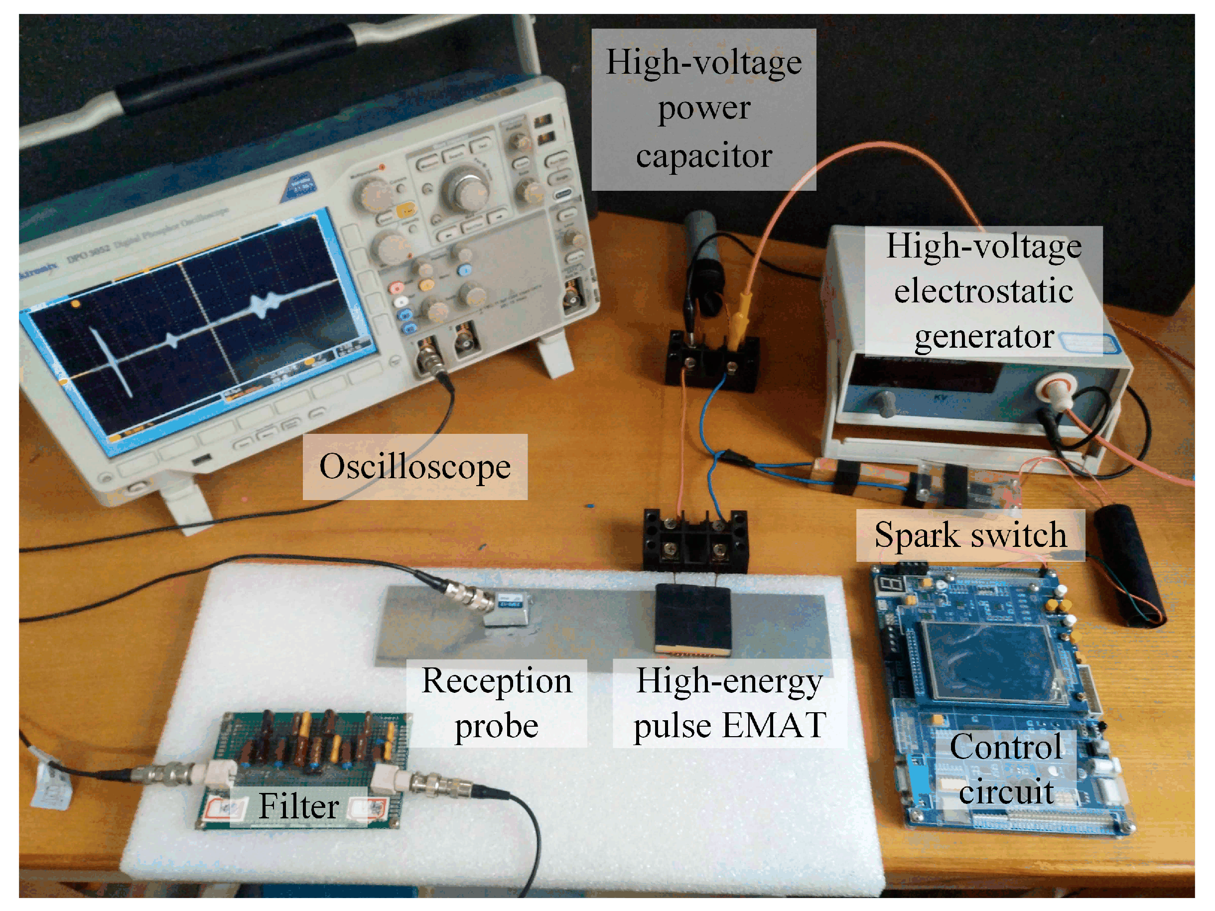
The high-energy pulse EMAT experiments were conducted on the test stand shown in Figure 11. The analysis of received ultrasonic signals, high-energy pulse lift-off characteristics, and defect detection experiments were carried out.
5.1. Received Ultrasonic Signal Analysis of High-Energy Pulse EMAT
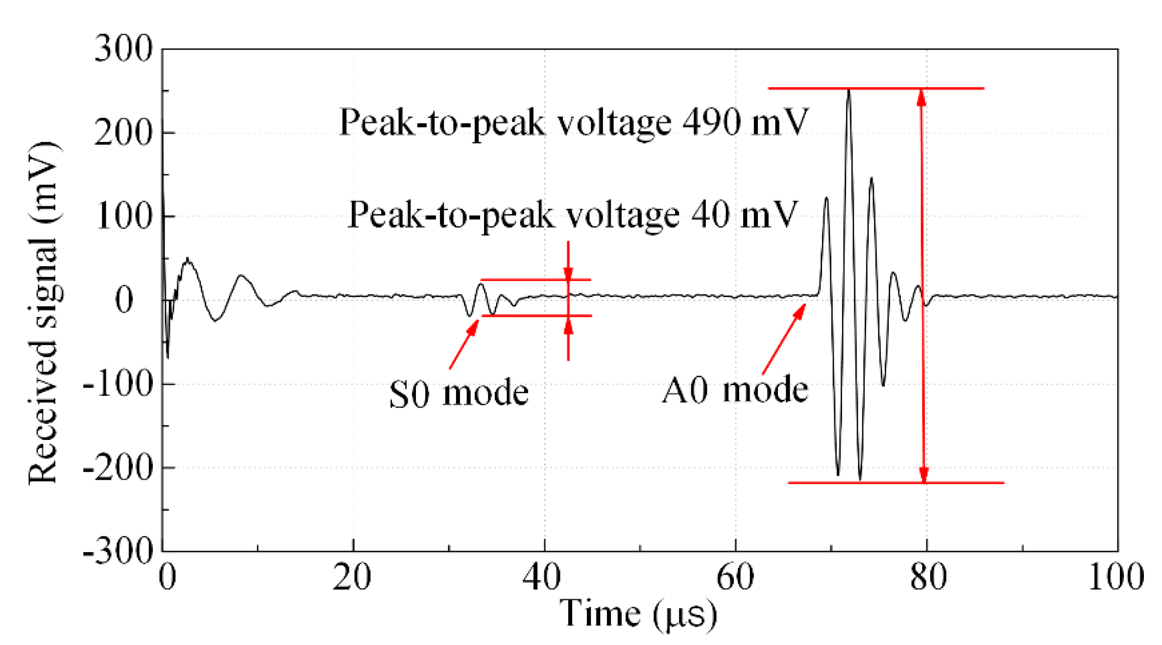
In the paper, the high-energy pulse EMAT was designed to excite the Lamb wave with A0 as the primary mode. And the experiment about the effect of high-energy pulse EMAT excitation Lamb wave was carried out. At lift-off distance h = 0 mm, the Lamb wave excited by the high-energy pulse EMAT is shown in Figure 12.
In Figure 12, the arrival time of the Lamb wave S0 mode direct wave is 31.01 μs, the arrival time of the A0 mode direct wave is 68.15 μs, and the distance of the transceiver is 170 mm. The calculated S0 group velocity is 5482 m/s and A0 group velocity is 2494 m/s. The theoretical value of the S0 group velocity is 5489 m/s and that of the A0 group velocity is 2498 m/s. Within the error tolerance range, the experimental results and theoretical values are the same. At the lift-off distance h = 0 mm, the A0 mode peak-to-peak value is 490 mV, and the S0 mode peak-to-peak value is 40 mV. The signal strength of A0 mode is much higher than that of S0 mode.
5.2. Lift-Off Characteristic of High-Energy Pulse EMAT
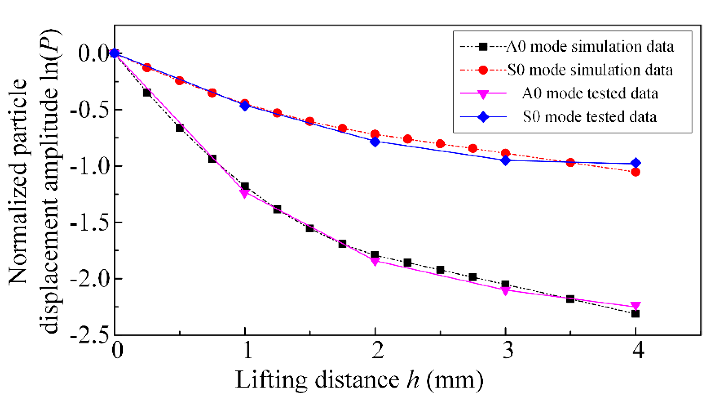
The induced eddy current and magnetic field in the skin layer of the steel plate are very sensitive to the change of lift-off distance. The magnetostrictive force is directly affected by the magnetic flux density in the steel plate. The Lorentz force is generated by the interaction of the magnetic field and the induced eddy current in the steel plate. It is necessary to analyze the effect of the Lamb wave excited about the lift-off distance in the steel plate. Acoustic propagation experiments were carried out at different lift-off distances, and the Lamb wave amplitude data were extracted at the lift-off distance from 0 mm to 4 mm. The normalized data was obtained by taking the logarithm of the Lamb wave data as the reference at the distance h = 0 mm, and the logarithm of the normalized data was obtained. Figure 13 shows the (h, ln(P)) curves at different distances. P is the amplitude of the received ultrasonic wave.
In Figure 13, as the lift-off distance h increases, the Lamb wave S0 mode and A0 mode signals gradually decay, and the attenuation rate of S0 is significantly lower than that of A0. When the lift-off distance h > 2 mm, the attenuation amplitude and noise amplitude of the Lamb wave A0 mode are in the same order of magnitude. The experimental result deviates from the expected result. However, when the lift-off distance h ≤ 2 mm, the Lamb wave signal is clear and easy to identify. The experimental results are consistent with the simulation expectation. Therefore, when the lift-off distance is small, the Lorentz force FL and the magnetostrictive force fM work together to make the particle vibrate periodically to excite Lamb waves in the steel plate. The Lorentz force FL decays faster than the magnetostrictive force fM with the lift-off distance increases. When the lift-off distance is larger, the Lorentz force transduction efficiency decays to negligible. The high-energy pulse electromagnetic acoustic transduction mechanism in the steel plate is mainly dominated by magnetostrictive force.
5.3. High-Energy Pulse EMAT Defect Detection
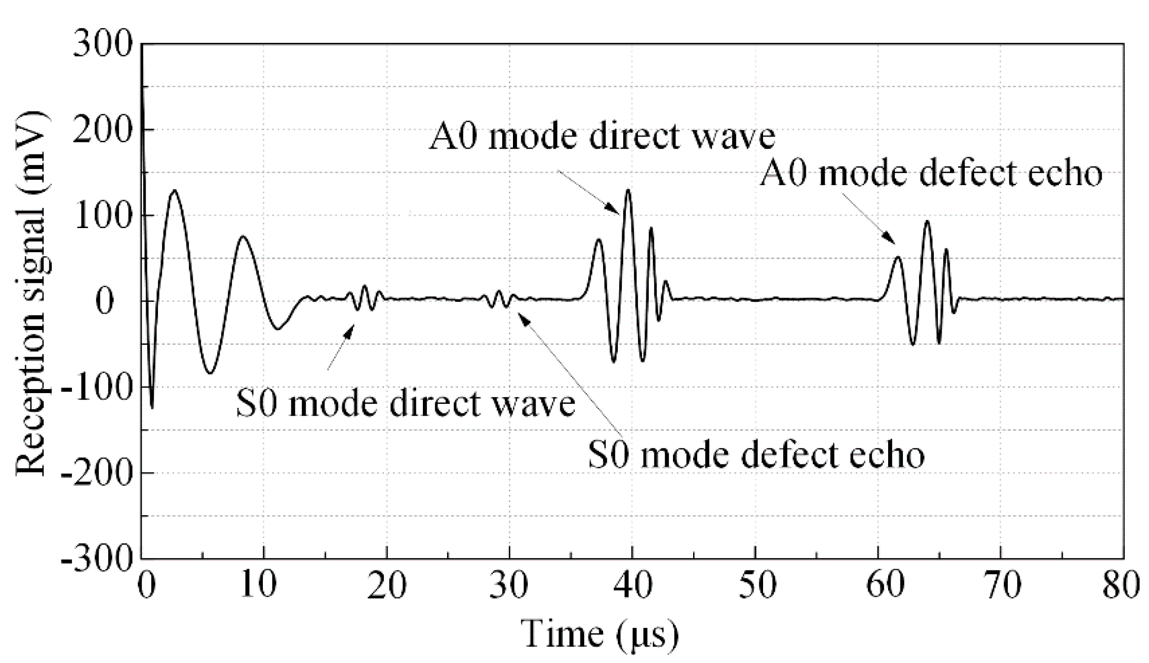
In the paper, Lamb waves with A0 mode as the main mode is used to detect the surface crack defects of steel plates. As shown in Figure 14, the size of the steel plate is 600 mm × 60 mm × 1 mm, the crack depth is 1 mm, the crack width is 0.4 mm, the crack length is 30 mm, and the lift-off distance of the high-energy pulse excitation device is 1 mm. The distance between the receiving and transmitting parts is 90 mm, and the distance from the high-energy pulse power excitation device to the defect is 30 mm.
As shown in Figure 15, the direct wave and defect echo of A0 mode are very clear. The position of crack defect can be determined by the time difference between the direct wave and the defect echo.
In defect localization, the direct wave’s arrival time of A0 mode is 36.1 μs, and the defect echo’s arrival time of A0 mode is 60.1 μs. The group velocity of A0 mode is 2494 m/s measured by the frequency characteristic experiment. The calculated distance from the excitation device to the defect is 29.93 mm, and the actual distance is 30 mm. The accurate positioning of the defect was achieved.
6. Conclusions
In this paper, the transduction mechanism of the dynamic, strong magnetic field generated by the coil and the eddy current interaction to excite the acoustic wave in the steel plate was studied. The Lamb wave high-energy pulse EMAT with the primary mode of excitation A0 was designed. Experiments were performed in the steel plate with ultrasonic lift-off characteristics and defect detection. The simulation and experimental results showed that the induced magnetostrictive force and Lorentz force of the high-energy pulsed electromagnetic acoustic transducer with a meander coil are not completely superimposed. The displacement amplitude attenuation rule is different when the lift-off distance is close to 2 mm. Compared with the conventional EMATs, the high-energy pulse EMAT avoids the magnetic force attracted by the magnet to the steel plate and reduces the attenuation of the acoustic signal effect about the lift-off distance, which is meant for new applications. In the subsequent work, the improvement of the power capacitor to increase the excitation energy of the system and the miniaturization of the external circuit of the EAMT are the directions for improvement.
Author Contributions
Conceptualization, writing—review and editing, project administration, funding acquisition, S.L.; methodology, data curation, writing—original draft preparation, K.C.; validation, S.L. and C.Z.; software, L.J.; resources, Q.Y.; All authors have read and agreed to the published version of the manuscript.
Funding
This research was funded by the National Natural Science Foundation of China (grant number 51777052), the National Natural Science Foundation of China (grant number 51977058), and the Natural Science Foundation of Hebei Province (grant number E2017202055).
Conflicts of Interest
The authors declare no conflict of interest.
References
- Every, A.G. The importance of ultrasonics in nondestructive testing and evaluation. Ultrasonics 2014, 54, 1717–1718. [Google Scholar] [CrossRef] [PubMed]
- Furuya, Y.; Torizuka, S.; Takeuchi, E.; Bacher-Höchst, M.; Kuntz, M. Ultrasonic fatigue testing on notched and smooth specimens of ultrafine-grained steel. Mater. Des. 2012, 37, 515–520. [Google Scholar] [CrossRef]
- Clough, M.; Fleming, M.; Dixon, S. Circumferential guided wave EMAT system for pipeline screening using shear horizontal ultrasound. NDT E Int. 2017, 86, 20–27. [Google Scholar] [CrossRef] [Green Version]
- Trushkevych, O.; Edwards, R.S. Characterisation of small defects using miniaturised EMAT system. Ultrasonics 2019, 107, 102140:1–102140:9. [Google Scholar] [CrossRef]
- Thring, C.B.; Fan, Y.; Edwards, R.S. Focused Rayleigh wave EMAT for characterisation of surface-breaking defects. NDT E Int. 2016, 81, 20–27. [Google Scholar] [CrossRef] [Green Version]
- Ludwig, R.; Dai, X.-W. Numerical simulation of electromagnetic acoustic transducer in the time domain. J. Appl. Phys. 1991, 69, 89–98. [Google Scholar] [CrossRef] [Green Version]
- Thompson, R.B. Electromagnetic Generation of Rayleigh and Lamb Waves in Ferromagnetic Materials. IEEE Trans. Sonics Ultrason. 2005, 20, 340–346. [Google Scholar] [CrossRef]
- Zhang, C.; Li, F.; Liu, S.; Cai, Z.; Yang, Q. Impacts of the electromagnetic loading on the propagation of the ultrasonic wave. Trans. China Electrotech. Soc. 2017, 32, 102–107. [Google Scholar] [CrossRef]
- Miao, H.; Huan, Q.; Wang, Q.; Li, F. A new omnidirectional shear horizontal wave transducer using face-shear (d24) piezoelectric ring array. Ultrasonics 2017, 74, 167–173. [Google Scholar] [CrossRef] [Green Version]
- Mirkhani, K.; Chris, C.; Chris, M.; Maciej, J.; Tomas, D.; Anthony, S.; Reza, J.S.; Adalbert, K.; Marcello, P. Optimal Design of EMAT Transmitters. NDT E Int. 2004, 37, 181–193. [Google Scholar] [CrossRef]
- Jian, X.; Dixon, S.; Grattan, K.T.V.; Edwards, R.S. A model for pulsed Rayleigh wave and optimal EMAT design. Sens. Actuators A 2006, 128, 296–304. [Google Scholar] [CrossRef]
- Wang, S.; Su, R.; Chen, X.; Kang, L.; Zhai, G. Numerical and experimental analysis of unidirectional meander-line coil electromagnetic acoustic transducers. IEEE Trans. Sonics Ultrason. 2013, 60, 2657–2664. [Google Scholar] [CrossRef] [PubMed]
- Seung, H.M.; Park, C.I.; Kim, Y.Y. An omnidirectional shear-horizontal guided wave EMAT for a metallic plate. Ultrasonics. 2016, 69, 58–66. [Google Scholar] [CrossRef] [PubMed]
- Liu, Z.; Hu, Y.; Xie, M.; Wu, B.; He, C. Development of omnidirectional a0 mode emat employing a concentric permanent magnet pairs with opposite polarity for plate inspection. NDT E Int. 2018, 97, 13–21. [Google Scholar] [CrossRef]
- Hirao, M.; Ogi, H. Electromagnetic Acoustic Transducers: Noncontacting Ultrasonic Measurements Using EMATs, 2nd ed.; Springer: Tokyo, Japan, 2017. [Google Scholar] [CrossRef]
- Hirao, M.; Ogi, H. EMATs for Science and Industry: Noncontacting Ultrasonic Measurements; Springer: Boston, MA, USA, 2003; pp. 39–67. [Google Scholar] [CrossRef]
- Ogi, H. Field dependence of coupling efficiency between electromagnetic field and ultrasonic bulk waves. J. Appl. Phys. 1997, 82, 3940–3949. [Google Scholar] [CrossRef]
- Ribichini, R.; Nagy, P.B.; Ogi, H. The impact of magnetostriction on the transduction of normal bias field EMATs. NDT E Int. 2012, 51, 8–15. [Google Scholar] [CrossRef]
- Ashigwuike, E.C.; Ushie, O.J.; Mackay, R.; Balachandran, W. A study of the transduction mechanisms of electromagnetic acoustic transducers (emats) on pipe steel materials. Sens. Actuators A 2015, 229, 154–165. [Google Scholar] [CrossRef]
- Ren, W.; Xu, K.; Dixon, S.; Zhang, C. A study of magnetostriction mechanism of EMAT on low-carbon steel at high temperature. NDT E Int. 2019, 101, 34–43. [Google Scholar] [CrossRef] [Green Version]
- Rueter, D. Induction coil as a non-contacting ultrasound transmitter and detector: Modeling of magnetic fields for improving the performance. Ultrasonics 2016, 65, 200–210. [Google Scholar] [CrossRef] [Green Version]
- Rueter, D.; Morgenstern, T. Ultrasound generation with high power and coil only EMAT concepts. Ultrasonics 2014, 54, 2141–2150. [Google Scholar] [CrossRef] [Green Version]
- Rueter, D. Experimental Demonstration and Circuitry for a Very Compact Coil-Only Pulse Echo EMAT. Sensors 2017, 17, 926. [Google Scholar] [CrossRef] [PubMed] [Green Version]
- Tkocz, J.; Greenshields, D.; Dixon, S. High power phased EMAT arrays for nondestructive testing of as-cast steel. NDT E Int. 2019, 102, 47–55. [Google Scholar] [CrossRef]
- Rieger, K.; Erni, D.; Rueter, D. A compact and powerful EMAT design for contactless detection of inhomogeneities inside the liquid volume of metallic tanks. Tm. Tech. Mess. 2020, 87, 349–359. [Google Scholar] [CrossRef]
- Boni, E.; Bassi, L.; Scaringella, M.; Ramalli, A.; Tortoli, P. Design of a multiple-rail high-voltage power supply for ultrasound scanners. In Proceedings of the IEEE International Ultrasonics Symposium (IUS), Chicago, IL, USA, 3–6 September 2014. [Google Scholar] [CrossRef]
- Turner, S.L.; Rabani, A.; Axinte, D.A.; King, C.W. Dynamic ultrasonic contact detection using acoustic emissions. Ultrasonics 2014, 54, 749–753. [Google Scholar] [CrossRef] [PubMed]
- Ludwig, R. Theoretical basis for a unified conservation law description of the electromagnetic acoustic transduction process. IEEE Trans. Ultrason. Ferroelectr. Freq. Control. 1992, 39, 76–480. [Google Scholar] [CrossRef] [PubMed]
Figure 1.
Magnetization process of high-energy pulse excitation.

Figure 2.
High-energy pulse EMAT. (a) Excitation principle of the high-energy pulse EMAT; (b) High-energy pulse EMAT finite element simulation model.
Figure 2.
High-energy pulse EMAT. (a) Excitation principle of the high-energy pulse EMAT; (b) High-energy pulse EMAT finite element simulation model.

Figure 3.
The characteristics of high-energy pulse excitation. (a) Current in excitation coil of the high-energy pulse EMAT simulation; (b) The spectrum of high-energy pulse EMAT excitation.
Figure 3.
The characteristics of high-energy pulse excitation. (a) Current in excitation coil of the high-energy pulse EMAT simulation; (b) The spectrum of high-energy pulse EMAT excitation.

Figure 4.
Magnetic flux density in steel plate. (a) Horizontal component of magnetic flux density; (b) vertical component of magnetic flux density.
Figure 4.
Magnetic flux density in steel plate. (a) Horizontal component of magnetic flux density; (b) vertical component of magnetic flux density.

Figure 5.
The received signals of high-energy pulse EMAT and conventional EMAT at the lift-off distance h = 0 mm in the simulation.
Figure 5.
The received signals of high-energy pulse EMAT and conventional EMAT at the lift-off distance h = 0 mm in the simulation.

Figure 6.
The relation between the logarithm of S0 mode and A0 mode amplitudes and lift-off distance in the simulation.
Figure 6.
The relation between the logarithm of S0 mode and A0 mode amplitudes and lift-off distance in the simulation.

Figure 7.
High-energy pulse power supply schematic.

Figure 8.
The characteristics of the received current in the excitation coil. (a) Time domain diagram of current; (b) frequency domain diagram of current.
Figure 8.
The characteristics of the received current in the excitation coil. (a) Time domain diagram of current; (b) frequency domain diagram of current.


Figure 9.
Excitation coil.

Figure 10.
SCM trigger sequence of trigger circuit.

Figure 11.
Experimental system of high-energy pulse EMAT.

Figure 12.
Received Lamb at the distance h = 0 mm.

Figure 13.
The A0 and S0 modes received signal change with the lift-off distance.

Figure 14.
Steel plate defect detection.

Figure 15.
A0 mode Lamb wave defect detection.


Table 1.
The parameters of the model.
| Parameter | Value |
|---|---|
| Steel plate size width × height (mm) | 300 × 1 |
| Lift-off distance (mm) | 0–4 |
| Circular section wire diameter (mm) | 1 |
| Coil turn number | 4 |
| Frequency f (kHz) | 220 |
| Young modulus E (GPa) | 200 |
| Poisson ratio μ | 0.3 |
| Conductivity γ (MS/m) | 99.3 |
© 2020 by the authors. Licensee MDPI, Basel, Switzerland. This article is an open access article distributed under the terms and conditions of the Creative Commons Attribution (CC BY) license (http://creativecommons.org/licenses/by/4.0/).
Share and Cite
MDPI and ACS Style
Liu, S.; Chai, K.; Zhang, C.; Jin, L.; Yang, Q. Electromagnetic Acoustic Detection of Steel Plate Defects Based on High-Energy Pulse Excitation. Appl. Sci. 2020, 10, 5534. https://doi.org/10.3390/app10165534
AMA Style
Liu S, Chai K, Zhang C, Jin L, Yang Q. Electromagnetic Acoustic Detection of Steel Plate Defects Based on High-Energy Pulse Excitation. Applied Sciences. 2020; 10(16):5534. https://doi.org/10.3390/app10165534
Chicago/Turabian StyleLiu, Suzhen, Ke Chai, Chuang Zhang, Liang Jin, and Qingxin Yang. 2020. "Electromagnetic Acoustic Detection of Steel Plate Defects Based on High-Energy Pulse Excitation" Applied Sciences 10, no. 16: 5534. https://doi.org/10.3390/app10165534
Note that from the first issue of 2016, this journal uses article numbers instead of page numbers. See further details here.