1. Introduction
In response to global warming, sustainable energy technologies are being promoted worldwide to reduce carbon emission. The Chinese government has announced that China will reduce carbon dioxide emissions per unit of GDP by 40–45% in 2020 when compared to the 2005 baseline [
1]. The EU Energy Efficiency Directive (2012/27/EU) and the amending directive (2018/2002) have announced a series of binding measures to achieve a 20% energy efficiency target by 2020 [
2]. To reach these targets, great efforts must be made for space conditioning, as building comfort consumes a large proportion of energy; in particular, this amounts to around half of the expended energy in the EU [
3]. In the UK, the method by which heat is generated, distributed and used in buildings has to be changed to achieve a supply of affordable, secure and low-carbon energy for all consumers [
4]. Heat has traditionally been generated on-site in individual buildings, with the most common sources being electric heaters, gas boilers and oil boilers. District heating, also called a heat network, involves multi-building heating, in which heat is transported by circulating either hot water or low-pressure steam through a network of insulated pipes [
5,
6]. According to IEA energy balances, Russia, China and the European Union were responsible for 85% of district heating activities globally [
7]. The main user categories of district heating are industries and residential buildings [
8].
The government’s Strategic Framework for Low-Carbon Heating in the UK identified in 2016 that heat networks represented an important element to achieve the decarbonization of heat in buildings. However, to realize significant emissions reduction with district heating, the heat in the networks must be provided from low-carbon sources [
5]. This is also a global trend, with renewable energy usage showing an increasingly large share in the district heating system market, especially in the European Union (27%) and the USA (13%) [
5]. Among the possible renewable sources of energy, vertical-closed ground source heat pump (GSHP) systems can be an effective low-carbon solution that is compatible with district heating. A buried borehole heat exchanger is used to extract shallow geothermal energy from the ground. According to Lake et al. [
9], careful consideration should be given to the availability of nearby energy sources. The greatest advantage of this system is that there are no location restrictions for this technology, and underground energy sources are stable for long-term use. The benefits of GSHP systems also include their low running costs, minimal maintenance costs and long-life expectancy. A report from Kensa Heat Pumps indicates that heat pumps can be expected to have a lifetime of 20–25 years, and a borehole can be used for as long as 100 years [
10]. In order to encourage the growth of this technology, the Renewable Heat Incentive (RHI) classified GSHP district heating as a non-domestic tariff stream; thus, users of this system are eligible to receive 9.36 pence per kWh heating consumed for as long as 20 years [
11].
Combining cooling with a district heating system can make district energy more economically attractive, especially in areas with a mix of land use buildings [
4,
5,
12]; furthermore, it is considered to be more efficient for energy resource utilization [
13]. GSHP systems are perfectly suited to match this requirement, as cooling supply is a basic function of a GSHP system. In addition, the combination of heating and cooling together can benefit system efficiency and the temperature balance underground.
The utilization of shallow geothermal energy as an energy source for a district heating system is currently concentrated in the hybrid systems [
14], which means systems which integrate a GSHP in a heat network to provide part of the heating load. In Europe, over 50 successful schemes of this type have been running for over a decade [
5]. According to the regional application analysis of GSHP in Shenyang, China [
1], significant efforts have been made to increase the adoption of this technology to 59.41 million m
2 from 780 projects, and policies have been implemented to plan GSHP technology at the urban district and county level. Regional application could contribute to an anticipated 4.18% of CO
2 savings in Shenyang’s building sector. The city-scale analysis of GSHP application in London [
15,
16] showed that a high proportion (over 60%) of buildings have a C/D ratio (the ratio of ground capacity to energy demand) of over 1.0, meaning that many houses and buildings have sufficient space to install a GSHP and thus fully satisfy their own heating demands. In addition, it was found that buildings demonstrated significant spatial heterogeneity in C/D ratios due to variations in heating demand and available space. If a spatial sharing strategy can be introduced, buildings with high C/D ratios will be able to share their surplus capacity with their neighbors, allowing the heating and cooling demands of a greater number of buildings in the area to be satisfied. Alavy et al. [
17] built a utility model of a district hybrid GSHP system combining multiple commercial/industrial buildings to show that intelligent chosen combinations can reduce the required ground loop length and thus diminish the drilling space. De Carli et al. [
18] conducted a study on a heating and cooling district in a mild climate based on GSHP and specifically analyzed the influence of the district heating layout and population density in the district on the most suitable solution. From both energetic and economical points of view, sharing can be a good way to bring benefits and, in some cases, splitting a district centralized system into two sub-systems can reduce the financial risks. In fact, in addition to the cost consideration, Soga et al. [
19] simulated a case study at the city scale in London to investigate the influence of district size on the application potential of GSHP systems, which demonstrated that the use of a 50 m × 50 m area can greatly improve the potential compared with individual system planning, but the improvement rate decreased as the district sharing size increased. According to the existing research, it can be seen that district sharing can benefit GSHP applications, and sharing performance can be changed by building types and demand intensity. However, researchers have mainly focused on the utilization of a centralized GSHP system on specific cases including certain building types, but no investigation has been made into a systematical analysis to evaluate how the mix of typical building types can influence district system performance. Moreover, GSHP systems have unique characteristics, so it is worthwhile to compare several specific sharing strategies under different district scenarios to demonstrate their application capacity and carbon-saving ability.
Accordingly, this study makes a number of contributions to the literature:
We develop two district sharing models specific for GSHP system application. The two sharing strategies in the models are (i) individual systems with borehole sharing and (ii) a central district system.
The performance of the models is tested on three selected districts in London. These districts are a representative 50 m × 50 m size and show the variety in the combination of typical building types. The results demonstrate the good performance of models regarding the sharing potentials and, according to the comparison analysis, the potentials vary according to the different building type combinations.
We evaluate the carbon-saving potential of the developed GSHP district systems, and the results show that the sharing strategies can significantly reduce carbon emissions compared with individual systems, which is beneficial in the attempt to create a low-carbon city.
The rest of this paper is organized as follows:
Section 2 introduces the district heating network and illustrates our two proposed sharing strategies. Following this, the whole methodology for GSHP district system modeling and the parameter selections are provided in
Section 3. In
Section 4, the performance of models and calculation results of carbon emissions are demonstrated for the comparison analysis of selected districts. Finally, we summarize our work and provide conclusions in
Section 5.
2. GSHP District Sharing System
According to the Department of Energy and Climate Change (DECC) definition, a district heating network consists of two or more distinct buildings connected to a single heat source or a building in which there are more than 10 individual customers connected to a single heat source. For domestic buildings in the UK, by connecting with at least one neighbor, the eligible grant category can switch from the Domestic Renewable Heat Incentive (RHI) to Non-Domestic RHI. The Domestic RHI is intended for domestic applications of ground source heat pumps, and the payment is at a rate of 20.46 p/kWh of renewable heat generated for 7 years. The Non-Domestic RHI, also known as the Commercial RHI, deals mainly with commercial applications or “district” heating schemes in domestic properties, and the payment is at a rate of 9.36 p/kWh on the first 1314 h of eligible energy produced, followed by 2.79 p/kWh on any additional heat produced for 20 years [
19]. The network size is also defined on the basis of the number of domestic and non-domestic customers connected to the heat source. There are large networks (500 or more residential properties and/or more than 10 non-domestic users), medium networks (between 100 and 500 residential properties and/or between three and 10 non-domestic users and small networks (less than 100 residential properties and/or less than three non-domestic users). Currently, in the UK, the smaller-sized networks are predominant, representing 75% of the 1765 individual district heating networks. The average number of dwellings per network is 35. Medium and large-sized networks make up the rest of the total, at 20% and 5%, respectively [
20].
The size of GSHP district heating systems can range from micro to macro scales. By linking systems together, the system capacity can be enhanced by drilling deeper boreholes and making borehole locations more flexible [
10]. As commercial buildings often have different heat demand timings compared with residential buildings, this temporal heterogeneity can benefit the energy use efficiency of a shared system. With respect to the available space for borehole installation, residential houses can share their surplus geothermal energy with commercial buildings and urban infrastructure at a large scale to achieve a low-carbon city. In addition, residential houses can benefit from more generous tariff benefits by switching to a district network, because the eligible incentive scheme can change from domestic to non-domestic.
However, in practical situations, buildings within a certain district generally belong to different landlords, and it is therefore not always feasible to have a central system for a whole district. In this case, it is also recommended to design individual systems for buildings but allow systems to share shallow geothermal energy underground spatially, meaning to share their land with each other to install borehole heat exchangers. The landlords can make a contract to confirm a rental fee as a part of the initial cost and run their own heat pump systems separately to avoid operation conflicts. In this way, arguments in the negotiation of the operation management can be reduced, which can be considered to enhance the feasibility of implementing the district system. However, as there is no limitation to installing closed-loop GSHP systems in the UK, the subjective opinions of landlords are always a dominant factor in the feasibility of building a district sharing system and vary by case.
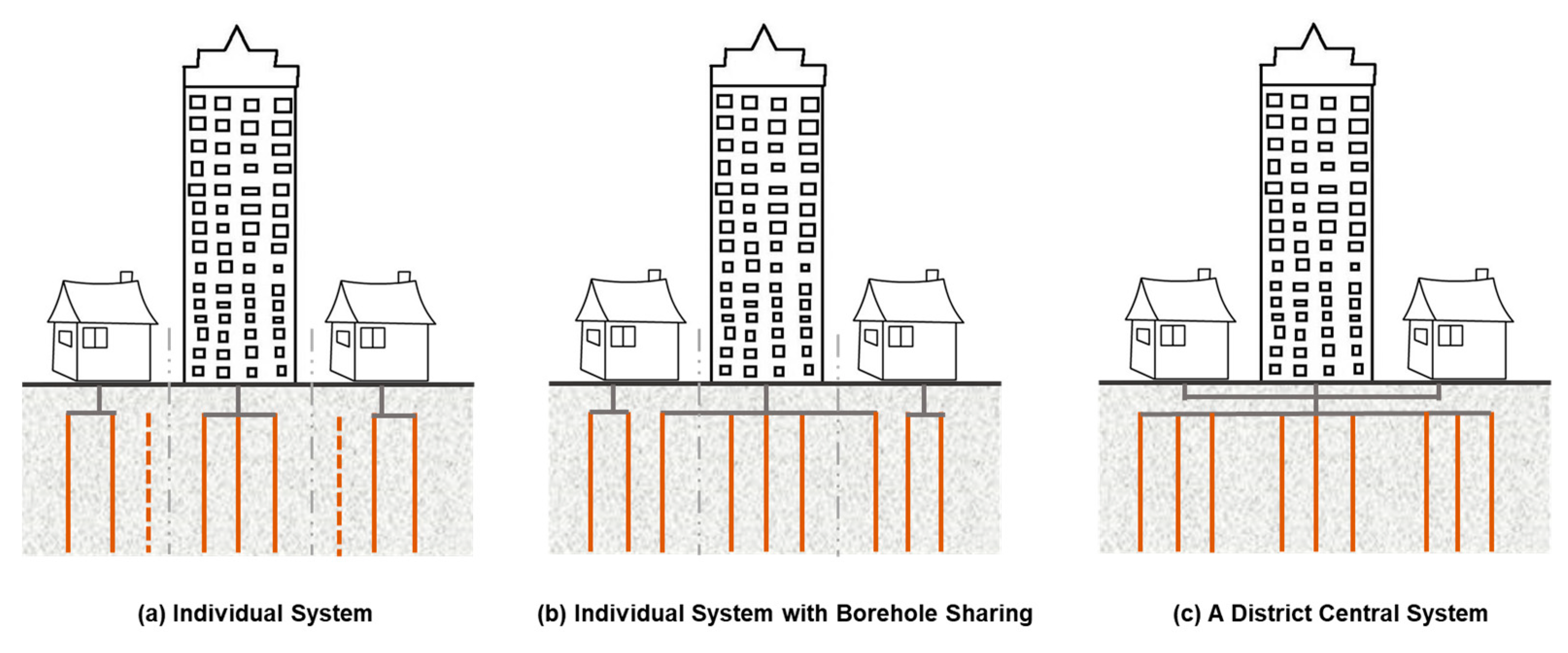
Therefore, in this study, two sharing strategies were considered for a district GSHP system: (i) individual systems with borehole sharing (
Figure 1b) and (ii) a central district system (
Figure 1c). For the individual system shown in
Figure 1a, the dotted line shows that the residential buildings have surplus space for borehole installation. For the individual systems with borehole sharing, a GSHP system was designed for each building based on their individual energy demand, but all the individual systems within the district can share the land with each other for borehole installation. Buildings with surplus space for installation can rent their land to a building with insufficient space. For the central district system, the energy demands of all the buildings within the district are considered as a whole for the GSHP system design. The designed system can use either a large central heat pump or multiple smaller controlled heat pumps [
5]. In both cases, the heat pumps should be connected to a communal ground array, including one or more borehole heat exchangers (BHE), to collect energy from the ground. As regards the installation and operation stages, in Strategy 1, the landlords must only consider the land rent and run their respective systems afterwards, while with Strategy 2, the landlords need to reacg ab agreement on the life cycle of the central system.
4. Results and Discussion
According to the application analysis at the city-scale, the C/D ratios of buildings show significant variation in terms of the different land use types; residential, retail and office buildings are the three major types in London. In addition, a size of 50 m × 50 m is more cost-effective for sharing than other larger grid sizes from the city-scale point of view [
16,
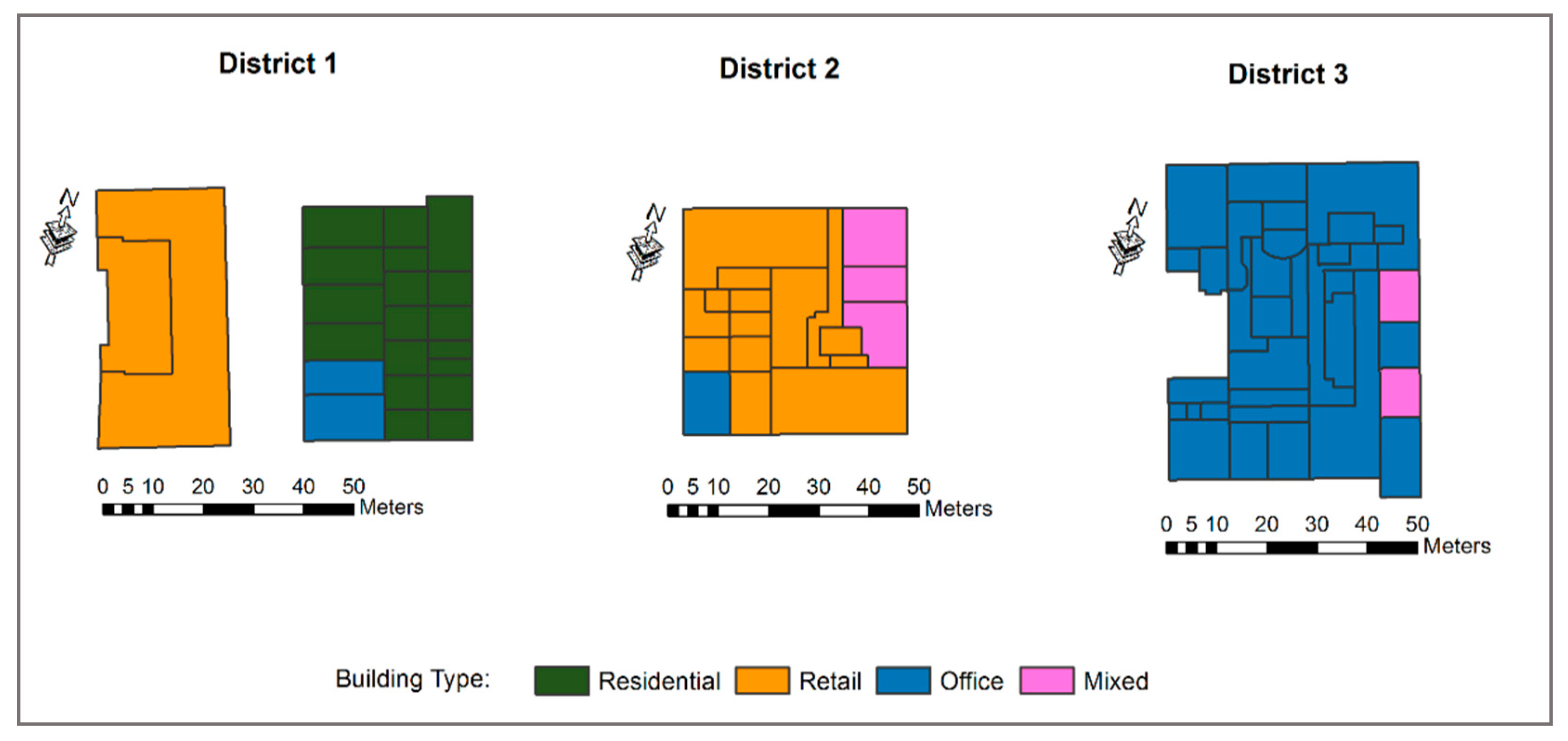
25]. Therefore, to compare the influences of these two district sharing strategies on the application capacities of the GSHP system, three districts in London (
Figure 3) were selected as case studies. District 1 was a group of residential, retail and office buildings, District 2 was a group of retail, office and mixed-use buildings and District 3 had little heterogeneity as it was mainly composed of office buildings. All the GSHP systems in
Figure 1 (individual system, individual system with borehole sharing and central district system) were used for these districts to perform the comparison analysis.
4.1. Comparison of District Sharing Strategies on C/D Ratio and Required Borehole Number
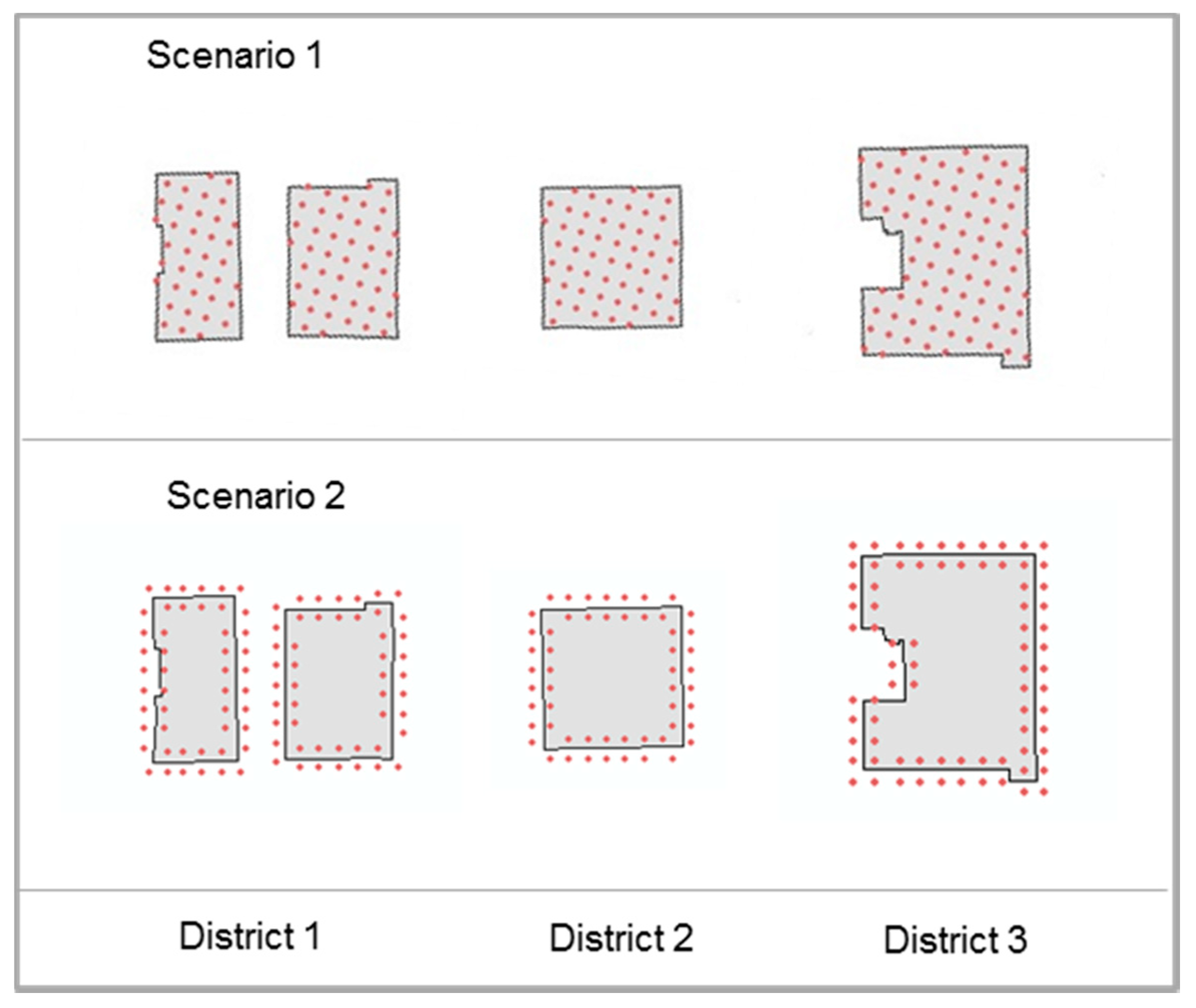
Two district GSHP systems with different sharing strategies were applied to the three selected districts for analysis. Two scenarios—Scenario 1 (boreholes under buildings) and Scenario 2 (borehole around buildings), shown in
Figure 4—were analyzed for comparison. The C/D ratio and required borehole number were used as indicators to demonstrate the performance of the two proposed district GSHP systems.
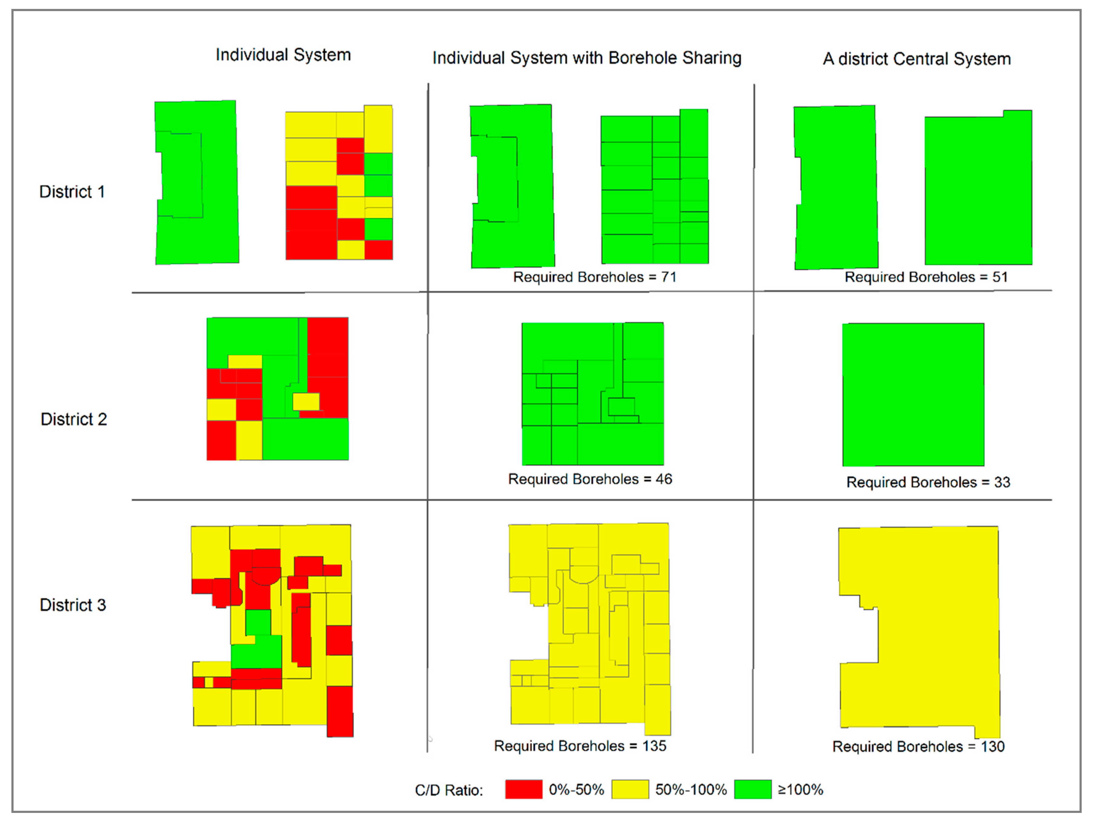
Figure 5 shows the C/D ratio and required borehole number of the three target districts with different sharing strategies under Scenario 1 (boreholes under buildings). For District 1, more than half of the buildings had C/D ratios in yellow and red colors with the individual GSHP system. With borehole sharing (Strategy 1,
Figure 1b), although the required borehole number remained the same, the C/D ratio of the whole district turned to a green color, which showed that heating and cooling demands could be fully satisfied by sharing the land for borehole installation. The performance of implementing a central district system (Strategy 2,
Figure 1c) showed an even better result, in that the required borehole number could be reduced from 71 to 51 while still satisfying all energy demands. In District 2, the results are quite similar to those of District 1. Sharing can allow the energy demand of the whole district to be fully satisfied, and a central district system can save a further 13 required boreholes, reducing the number from 46 to 33. As for District 3, mainly office buildings are present, and this type generally has a low C/D ratio range, which can be also seen from the figure. However, the district sharing also brought benefits to meeting the energy demand of the district, but the influence is not as significant as other two districts. The C/D ratio of the whole district turns to a yellow color with borehole sharing, and a district central system can only save 4% of the required boreholes, reducing the number from 135 to 130.
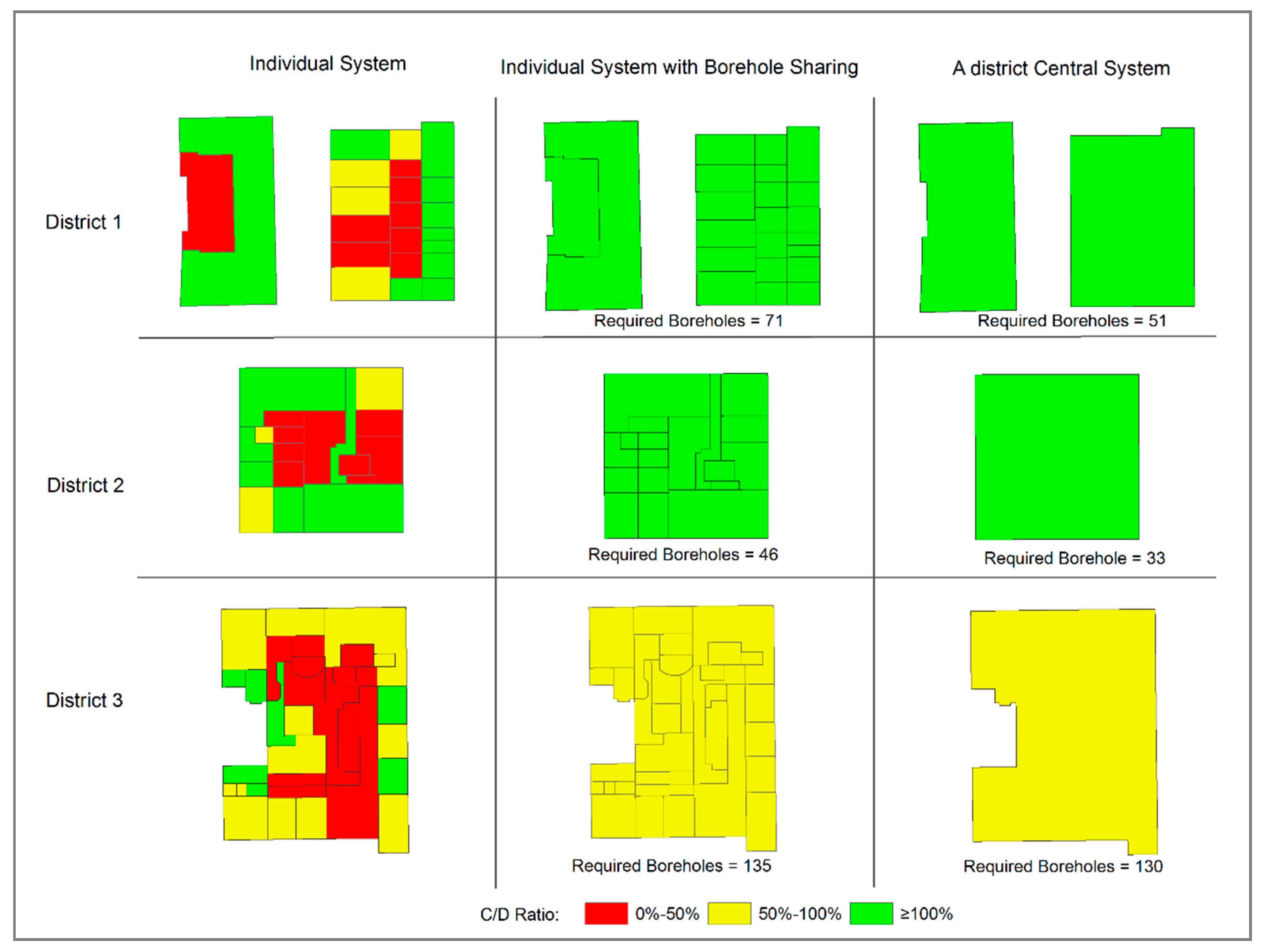
Figure 6 shows the C/D ratio and required borehole number of the three target districts with different sharing strategies under Scenario 2 (boreholes around buildings). In a similar manner to Scenario 1, for District 1, borehole sharing (Strategy 1,
Figure 1b) could enhance the C/D ratio of the whole district, shown by the green color, which means that heating and cooling demands can be fully satisfied by sharing the land for borehole installation. Employing a district central system (Strategy 2,
Figure 1c) saves 20 boreholes—reducing the number from 71 to 51—while still satisfying all energy demands. For District 2, the results are quite similar to those of District 1; sharing allows the whole district’s energy demands to be fully satisfied, and a central district system can further reduce the required number of boreholes from 46 to 33. As for District 3, borehole sharing makes the C/D ratio of the whole district turns to a yellow color, and a district central system reduces the number of required boreholes from 135 to 130.
As Scenarios 1 and 2 describe the borehole allocation methods, they can only influence the maximum borehole number which is allowed to be installed for the building (
), but not the required borehole number by the building to satisfy its heating and cooling demands (
). Therefore, in
Figure 5 and
Figure 6, the required borehole numbers for various sharing strategies are exactly the same under both scenarios. However, the different influences on
lead to the differences in the C/D ratios of the district.
Table 3 shows C/D ratios with various sharing strategies under Scenario 1 and Scenario 2 for Districts 1, 2 and 3, respectively. Although for both scenarios, the resulting ratios show the same range colors, their capacity potentials are varied; the reason for this is that many buildings in Westminster have a narrow and long shape, leading to more space being “around” than “under” the buildings, which was described in more detail in the paper of Zhang, et al. [
16]. For Districts 1 and 2, Strategy 2 outperforms Strategy 1 under both scenarios in terms of the C/D ratio. However, for District 3, the C/D ratio with Strategy 2 is lower than the value with Strategy 1 under both scenarios, due to the energy loss from the network in the district central system. The reason for this is that the savings in the required energy resulting from the central district system cannot cover the relative energy loss. Therefore, it can be seen that each sharing strategy is applicable to different kinds of districts.
In addition, among the three districts, for both scenarios (
Figure 5 and
Figure 6), the performances of the sharing strategies are the best in District 1, followed by District 2, and the worst results are found in District 3. There are two main reasons for this: the first is the building type contained in the district, and the second is the number of building types. In District 1, there is a group of residential, retail and office buildings; the residential type only has heating demand and demonstrates a relatively high C/D ratio, ranging around 126%, but the office type has a 20% higher average cooling demand than heating and shows a lower C/D level of 70.8%, and thus there is a good balance of demands between the different types of building within the district. For District 2, there is a group of retail, office and mixed-use buildings; all these buildings have both heating and cooling demands, but retail types have a higher C/D ratio range with an average value of 154% than the office ones with 74.5% and the mixed ones with 55.0%, so the office buildings can still borrow some capacity from the retail buildings. As for District 3, there are mainly offices, and this is the type with the lowest C/D ratio range with an average value of 73.4%. Therefore, it can be seen that, for the C/D ratio, the residential and retail buildings have higher levels than the office buildings, and for the energy demand, the residential and retail buildings have more heating requirements while the office buildings require more cooling. A greater variety in building types and a greater differentiation in heating and cooling demands between these types can contribute to better district sharing performance with the application of a GSHP system.
4.2. Comparison of District Sharing Strategies on Carbon Emissions
In addition to meeting more energy demand, environmental benefits can also be obtained by district sharing systems. Therefore, CO
2 emissions were also calculated for comparison. We considered that, for the three districts, part of the energy demand not satisfied by the GSHP system was provided by electricity for heating and air conditioners for cooling. The equivalent emission factors for various heating and cooling systems can be seen in
Table 2. Both scenarios (boreholes under buildings and borehole around buildings) were analyzed. CO
2 emissions were calculated for “no GSHP”, “individual GSHP system”, “individual system with borehole sharing” and “central district system” for all three districts, respectively.
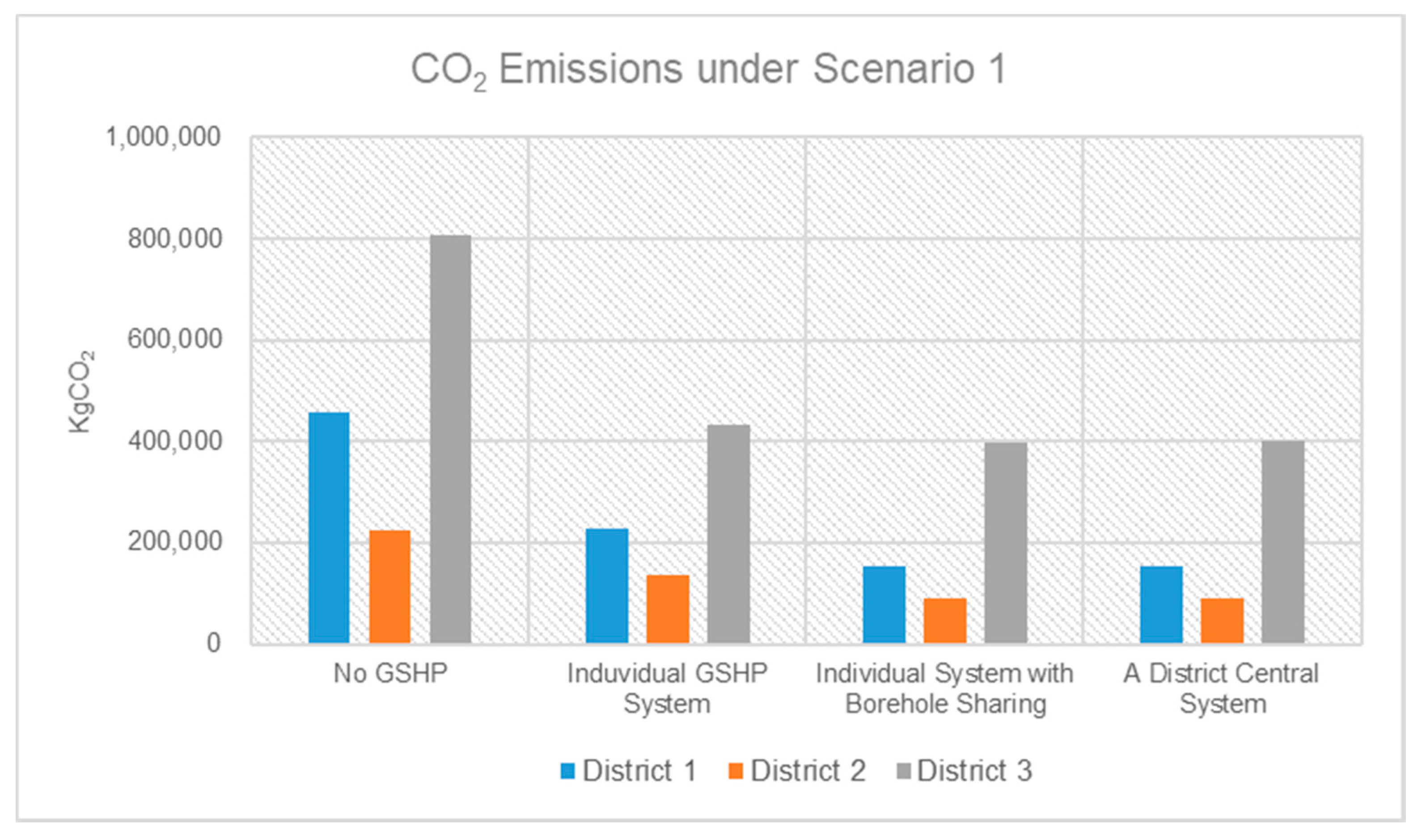
Figure 7 shows the CO
2 emissions of the three target districts with different heating and cooling systems under Scenario 1 (boreholes under buildings). For District 1, introducing GSHP systems for individual buildings could greatly reduce carbon emissions from around 460,000 kg to 229,000 kg. With district GSHP systems, the emissions can be further reduced to approximately 150,000 kg. Although the central district system (Strategy 2,
Figure 1c) showed a better C/D ratio than borehole sharing (Strategy 1,
Figure 1b), CO
2 emissions are the same because both of these ratios are higher than 100%, which means that both district systems can fully satisfy the energy demand. Similar to District 1, individual GSHP systems can reduce CO
2 emissions from around 224,000 kg (no GSHP system) to 135,000 kg in for District 2. Sharing can fully satisfy the energy demands of the whole district, and district systems can further cut the emissions to 91,000 kg. As for District 3, mainly office buildings are present, and this type generally has a high cooling demand; thus, the district sharing system benefits carbon emissions saving, but the influence is quite slight. Strategy 1 and Strategy 2 reduced emissions from 431,000 kg to 399,000 kg and 403,000 kg, respectively.
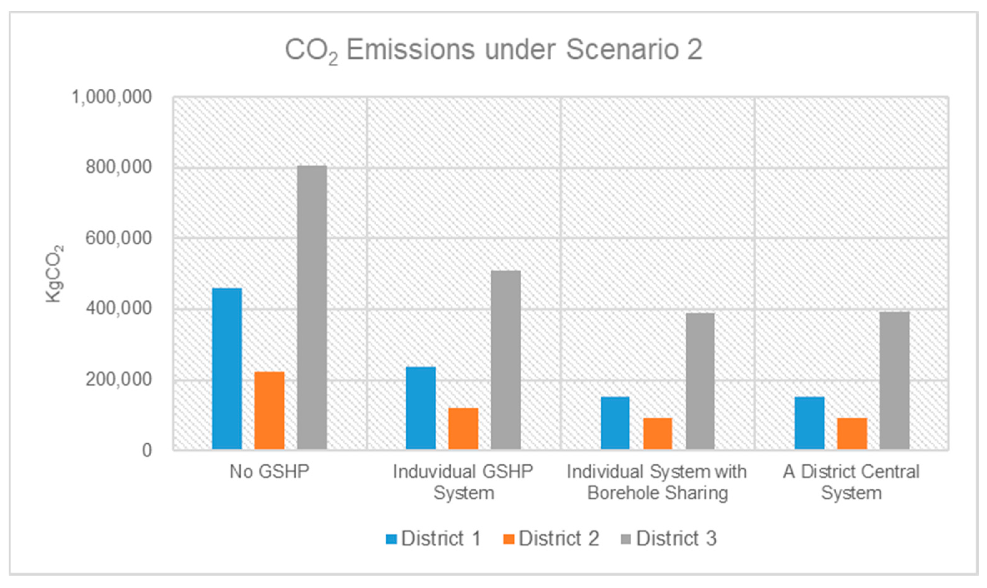
Figure 8 shows the CO
2 emissions of the three target districts with different heating and cooling systems under Scenario 2 (boreholes around buildings). For District 1, individual GSHP systems can significantly reduce carbon emissions from around 460,000 kg (electricity heating and air conditioner cooling) to 239,000 kg. The district sharing systems can further cut the emissions to approximately 150,000 kg. Similar to Scenario 1, although Strategy 2 showed a better C/D ratio Sharing Strategy 1, the influences on reducing CO
2 emissions are the same, because both of these ratios are higher than 100%, and the maximum energy supply can only be 100%. For District 2, individual GSHP systems can reduce CO
2 emissions from around 224,000 kg with no GSHP system to 120,000 kg. Both sharing strategies can fully satisfy energy demand and can further reduce the emissions to approximately 91,000 kg. As for District 3, the impacts of district sharing on carbon emissions saving are not as significant as the other two districts. Strategy 1 and Strategy 2 reduced emissions from 508,000 kg to 389,000 kg and 394,000 kg, respectively.
According to the results in
Figure 7 and
Figure 8, for District 1 and District 2, both sharing strategies can cut the carbon emissions by around 30–35% compared to individual GSHP systems, and the two strategies lead to the same emissions values for each district. The reason for this is that for both of the scenarios, the C/D ratios are higher than 100%, which shows the difference in supply capacity level, but in practice, the maximum energy demand can only be 100%. This means that Strategy 1 and Strategy 2 can both fully satisfy the energy demands for District 1 and District 2. However, for District 3, the situation is different: the C/D ratio is still in the yellow range with the application of district GSHP systems, so only part of the energy demand can be satisfied. Similar to the change trend of the C/D ratio, the CO
2 emissions savings with Strategy 2 are lower than with Strategy 1 under both scenarios due to the energy loss from the network in the district central system, but Scenario 2 demonstrates better performance in terms of emissions savings than Scenario 1 for District 3.
4.3. Discussion
According to the results obtained by implementing the sharing strategies in three districts in London, the sharing system can be seen to benefit both C/D ratio improvement and carbon emissions savings, but the sharing potential is different under various district situations. There are two main reasons for this: the building type contained in the district and the number of building types. In District 1, there are three types of building: residential, retail and office buildings. The residential and retail buildings have a relatively high C/D ratio and consume more energy for heating than cooling, while the office buildings have a low C/D ratio range and require more energy for cooling. The sharing improvements on capacity and carbon are significant in this district, and Strategy 2 shows an advantage over Strategy 1. In District 2, there are mainly two types of building: office and retail. The sharing also shows a good result, but this is weaker than in District 1. In District 3, only office buildings are present; the sharing potential is less efficient compared with the other two districts, and the results of the two strategies are closer to each other. Therefore, it can be seen that more building types and a high variety of building types can lead to better sharing potentials for both strategies. In addition, the central district system (CS, Strategy 2) performs better in for a higher potential sharing range, and the individual system with borehole sharing (ISBS, Sharing Strategy 1) performs better in a lower range. Based on the findings from case studies, it can be suggested that combining more building types can increase the application potential of district GSHP sharing systems; in particular, residential buildings are preferred in combination with others as they mainly require heating. Regarding the strategy selection, for a district containing more building types, it is better to employ a central district system (CS, Sharing Strategy 2), while for a district with only a single building type, an individual system with borehole sharing (ISBS, Sharing Strategy 1) is considered to be a better choice.
Therefore, it can be seen that, in the UK, the sharing application of GSHP systems can not only benefit the application capacity and carbon savings but also lead to a predictable economic improvement potential due to the Renewable Heat Incentive (RHI). To the best of our knowledge, the UK’s RHI is one of the most advanced initiatives worldwide to encourage the district sharing of GSHP applications, featuring detailed and specific inventive categories. There are also other financial incentives dedicated to district sharing support as well; for example, in France, for geothermal district heating, the national funding grants a bonus of €250 per ton of CO
2 emissions avoided, and the regional council provides a bonus of €350 per ton of CO
2 avoided for connecting new dwellings to existing geothermal heating networks [
26]. In the USA, qualifying residential GSHP systems are eligible for a 30% credit of the installation cost, and qualifying commercial systems can have a 10% credit [
27]. In Shandong Province in China, the incentive is ¥20/m
2 for GSHP, and in Henan Province, the incentive is ¥15/m
2 for either heating or cooling and ¥19.5/m
2 for both heating and cooling [
27]. However, in some other areas and counties, small-scale GSHP systems seem to be the main promoted target. In Germany, in new buildings, the support for GSHP is €10/m
2 of the used building area, up to €2000, and in refurbishment, the support is €20/m
2 of used building area, up to €3000 [
26]. These maximum amounts (€2000 or €3000) apparently demonstrate that this is a program which is primarily meant for small homes. In addition, according to the C/D ratio distributions in the three case studies, the green color (≥100%) accounts for a large part of the total. The main reason for this is that, in London, the buildings are mainly in the low-rise range, which means that the comfort demand are not excessive compared with the available energy underground. However, in a highly densely area, such as in mega cities in China, GSHP systems cannot afford to support the energy supply by themselves; thus, it is suggested to add GSHP systems into the hybrid thermal network in the district, and the sharing strategies can still be of benefit for energy efficiency in this situation.
5. Conclusions
This study developed two district sharing strategies specific for the application of a GSHP system and compared their performances in terms of the C/D ratio, required borehole number and carbon emissions in three selected districts in London.
It can be concluded from the case studies that a larger number of building types and a higher variety in building types, with greater differentiation in heating and cooling demands between these types, can lead to better district sharing performance for all the indicators—C/D ratio, required borehole number saving and carbon emissions—which means increased potential for the application of a GSHP system and more significant environmental impacts.
In addition, the central district system (CS, Strategy 2) shows better performance in the higher sharing potential range and the individual system with borehole sharing (ISBS, Sharing Strategy 1) in the lower range; thus, the sharing strategies are applicable to different kinds of districts. As for the strategy selection, for a district containing more building types, it is better to employ a central district system (CS, Strategy 2), while for a district with only a single building type, the individual system with borehole sharing (ISBS, Sharing Strategy 1) is considered to be better choice considering the application capacity and carbon emission savings. This study can support decision making for GSHP application planning for districts and provide a reference for district division and sharing strategy utilization.


