Effects of the Target on the Performance of an Ultra-Low Power Eddy Current Displacement Sensor for Industrial Applications


1
DISMI—Department of Sciences and Methods for Engineering, University of Modena and Reggio Emilia, 42122 Reggio Emilia, Italy
2
Centro Interdipartimentale InterMech MO-RE, 41125 Modena, Italy
3
Centro Interdipartimentale En&Tech, 42122 Reggio Emilia, Italy
4
IndioTECH srl, 42014 Castellarano (RE), Italy
*
Author to whom correspondence should be addressed.
Electronics 2020, 9(8), 1287; https://doi.org/10.3390/electronics9081287
Submission received: 28 July 2020
/
Revised: 7 August 2020
/
Accepted: 9 August 2020
/
Published: 11 August 2020
(This article belongs to the Special Issue Ultra-Low Power Circuits Design)
Abstract
:The demand for smart, low-power, and low-cost sensors is rapidly increasing with the proliferation of industry automation. In this context, an Ultra-Low Power Eddy Current Displacement Sensor (ULP-ECDS) targeting common industrial applications and designed to be embedded in wireless Industrial Internet of Things (IIoT) devices is presented. A complete characterization of the realized ULP-ECDS operating with different metallic targets was carried out. The choice of the considered targets in terms of material and thickness was inspired by typical industrial scenarios. The experimental results show that the realized prototype works properly with extremely low supply voltages, allowing for obtaining an ultra-low power consumption, significantly lower than other state-of-the-art solutions. In particular, the proposed sensor reached the best resolution of 2 µm in case of a carbon steel target when operated with a supply voltage of 200 mV and with a power consumption of 150 µW. By accepting a resolution of 12 µm, it is possible to further reduce the power consumption of the sensor to less than 10 µW. The obtained results also demonstrate how the performances of the sensor are strongly dependent on both the target and the demodulation technique used to extract the displacement information. This allowed for defining some practical guidelines that can help the design of effective solutions considering application-specific constraints.
1. Introduction
The demand for sensors is rapidly increasing with the proliferation of industrial automation and Industry 4.0 scenarios. At the same time, there is a growing request for smart, low-power, wireless, and low-cost devices. Among others, displacement sensors have an important role in many applications like the monitoring of Active Magnetic Bearings, AMBs, [1,2] gas turbine engines, [3], Blade Tip Clearance (BTC) in aero-engines [4], or the measurement of rotational angles in precision spherical joints [5]. Moreover, thanks to their intrinsic capabilities to also indirectly estimate material properties, they can be used to detect loose parts [6] and cracks [7,8,9], and measure other quantities (e.g., pressure, acceleration, wear of bearings [10] and disc cutters [11], or thicknesses [12,13]).
The most common displacement sensors exploit optical, capacitive, and eddy current operation principles. Optical sensors usually have a high resolution with a large measurement range, but they are often expensive and sensitive to optical contaminations and are, above all, power-hungry. Capacitive sensors can achieve extremely high resolution, but target grounding is necessary and they are sensitive to the properties of dielectrics placed in the measuring gap.
Conversely, Eddy Current Displacement Sensors (ECDSs) are contactless devices operating on the principle of magnetic induction, and they can precisely measure the position (displacement or proximity) of a metallic target even in contaminated environments (e.g., dust, oil particles, etc.) and through non-metallic materials such as plastics, dirt, etc. The main drawback of these sensors is the thermal drift that, under uncontrolled conditions, can affect the measurement. This is critical, especially for applications where (sub-) nanometric resolutions are required. In many other Industrial Internet of Things (IIoT) applications where resolutions in the order of micrometers are sufficient, like crankshaft concentricity and axial movement, spindle growth measurements, or roller gap measurements, this effect is not so critical, allowing for realizing low-cost devices without penalizing the performances.
1.1. Related Works
Most of the papers presented in the recent literature address two important aspects of the performance of an ECDS. The first one concerns the resolution of the sensor, while the second one concerns the thermal drift.
In more detail, different methods have been developed to enhance the resolution, such as measuring the variation of the working frequency of the sensor or precise amplitude demodulation. For example, a self-differential ECDS applied to an AMB system is presented in [1]. In this case, the driving AC signal needed for the proper operation of the ECDS is realized by using a Hartely-based oscillation circuit where the two needed coils also operate as sensing coils. Thanks to their symmetric position with respect to the target, a self-differential structure is obtained with the benefit of common-mode interference suppression and the consequent increase in resolution and sensitivity.
In [14], an integrated solution realized in AMS 0.35-μm 3.3-V Si/Ge BiCMOS technology is presented. Interestingly, the proposed one is a two-coil solution that, accordingly with the specific application of interest, can operate using either the coils as sensing elements in a differential configuration or just one coil as a sensing element and the other one as a reference. The sensor is driven by a 22 MHz AC signal. From one side, this allows for minimizing the skin effect of the generated eddy currents in the case of thin targets. On the other side, it forces the processing of relatively high frequency signals that affect the performance in applications requiring a sub-micrometer resolution (12.1 ENOB over the 1.5 mm measurement range) and power consumption (9.5 mW). A similar approach is used in [15], where the performances are improved with a 15 ENOB resolution at the cost of doubling the power consumption (i.e., 18 mW).
In [16], a differential sensor is embedded in an AC bridge with ultra-high resolution up to 0.05 nm obtained through the noise suppression of the AC bridge excitation voltage.
In [17], instead, a solution with two coils in an AC voltage source bridge is presented. One coil is used as a sensing probe, while the second one is used as a reference. Interestingly, the proposed solution allows for improving the thermal stability of the sensor by using self-temperature compensation when the environment temperature changes rapidly.
The thermal drift compensation is the second topic where the research efforts have recently been focused.
For example, in [18], a method based on binary regression is proposed to compensate the temperature drift effects of the sensing coil. Meanwhile, in [19], a dual-coil solution to compensate for the exponential hysteresis characteristic of the temperature drift errors of ECDSs operating in high-temperature environments is proposed. One coil is used as a displacement sensing coil, while the second one senses the distance from a compensation plate determined to have the same thermal hysteresis due to the combination of the thermal drift of the sensing coil and the thermal drift of the zone of the target where the eddy currents are induced. The sensing coil output signal and the compensation coil output signal are the input of an error elimination circuit based on a differential amplifier.
A differential dual-coil ECDS is also proposed in [20]. In this case, the target is food industry applications and it shows for the specific application that it is possible to identify within the measurement range a so-called temperature invariant region depending on the excitation frequency of the ECDS AC driving signal. It is shown how, within this region, the impact of the working temperature on the difference signal could be neglected.
In [21], instead, an axial ECDS with three sensing coils is proposed. Two coils are used to give the displacement information and eliminate the synchronous measuring error, while the third coil is an auxiliary probe opportunely positioned to sense a fixed distance. In this way, its sensing output is only related to the temperature variation consideration and can be used for temperature compensation.
All these solutions to compensate for the thermal drift rely on quite complex system architectures and have been developed for very specific applications with limited flexibility of usage. Moreover, no information about the power consumption is provided.
Power consumption and resolution are usually two opposite requirements. As mentioned before, several works show that the continuous power consumption cannot be lower than tens of milliwatts if micrometer, sub-micrometer, or sub-nanometer resolutions are required.
For example, in [22], a conventional sigma-delta scheme is suitably modified so that a non-contact inductive displacement sensor excited by a sinusoidal voltage source becomes integral to the delta modulator, providing a digital 11-bit resolution output signal. The circuit power consumption is 37.54 mW (36.9 mW due to the signal conditioning, 640 µW due to the sensing system).
In [23], instead, a 19.8 mW ECDS integrated interface intended for hi-tech applications is presented. The sensing coil is driven by a 126 MHz excitation frequency to minimize the skin effect and achieve high resolution and stability. It also uses an on-chip sensor offset compensation scheme, and, interestingly, exploits an amplitude demodulation scheme to extract the displacement information. Despite its very high resolution, this allows for containing the power consumption, which is mainly due to an extremely high excitation frequency signal.
1.2. Main Contributions of This Work
Most of the ECDSs proposed in the recent literature are focused on the improvement of the resolution by proposing complex solutions for very specific target applications with multiple sensing coils. Moreover, they use high frequency AC excitation signals for the sensing coils (in the order of tens or hundreds of megahertz). From one side, it allows for the use of several demodulation techniques to extract the displacement information. The pros and cons of each solution have been investigated and summarized in [24,25]. High-frequency excitation frequency signals are beneficial to improve the resolution and sensitivity of the ECDS, minimizing skin depth effects but, at the same time, are detrimental in terms of power consumption. As discussed previously, state-of-the-art solutions have a power consumption ranging from a few milliwatts to tens of milliwatts and above. This amount of power can usually be considered as low in many applications, but in many others, for example, where the sensor is embedded in a wireless battery-powered device, it leads to an unacceptable battery replacement rate. This is the case of most of the applications targeting Industry 4.0 or Industrial Internet of Things (IIoT) scenarios (e.g., concentricity or axial movement of a roller shaft in a conveyor belt) where resolutions in the order of few micrometers are sufficient.
Moreover, power consumption larger than 20 mW also amplifies the main drawback of ECDSs, which is related to the thermal drift [23].
In this context, the first main contribution of the paper is to demonstrate that it is possible to obtain an ECDS with power consumption in the order of a few microwatts and a resolution in the order of a few micrometers, suitable for a wide range of applications targeting IIoT scenarios. This extremely low power consumption, in first approximation, allows for overcoming the thermal drift drawback of classic ECDSs.
The achieved power consumption is noticeably lower than other state-of-the-art ECDSs presented in the recent literature and it could be the enabling factor for the further realization of a fully autonomous device by embedding an Energy Harvesting Device (EHD), customized accordingly, with the specific application and the real working scenario of the sensor.
The second main contribution concerns the investigation of the behavior of the proposed sensor in real working conditions, i.e., when used in combination with targets differing in material and/or thickness. From an application point of view, this is very important, because the target plays a key role in the performance of an ECDS. To optimize the performance of the sensor, to the best of our knowledge, almost all the targets used in the state-of-the-art solutions proposed in the recent literature are designed and customized opportunely. Unfortunately, in many real industrial applications, this is not possible. In many cases, the designer is forced to use as a target the component that has to be monitored, because additional components and/or additional manufacturing steps to existing parts (needed to use the optimal target material) lead to an increase in costs that is often not acceptable, or it is simply not feasible due to application-specific mechanical constraints.
In this perspective, the effects of the target on the performance of the sensor were evaluated by means of an experimental measurement campaign. In particular, the interaction of the realized ULP-ECDS with targets differing in material composition and thickness was investigated. The materials were chosen among the most used commonly in industrial applications, i.e., carbon steel, aluminum, and copper.
Finally, as described in the following section, the achieved power consumption was obtained by exploiting a very simple single sensing coil circuit architecture that is completely different from the complex ones used by the main state-of-the-art solutions presented in the recent literature. In particular, the proposed solution relies on a combination of the low-frequency AC excitation signal of the sensing coil and its amplitude demodulation to extract the displacement information.
2. Materials and Methods
This section describes the operating principle of the realized prototype of the ULP-ECDS. It is based on the same architecture of the one presented in [26], and it is detailed in the next subsections.
Whereas in [26], the main goal was to validate the proper operation of the realized ULP-ECDS, by using a single well-defined target, in this work, as mentioned before, the focus concerns the evaluation of the effects of different targets on the performance of the sensor in terms of power consumption and the shift of operation frequency, sensitivity, and resolution.
2.1. Operating Principle of the Realized Ultra-Low Power Eddy Current Displacement Sensor
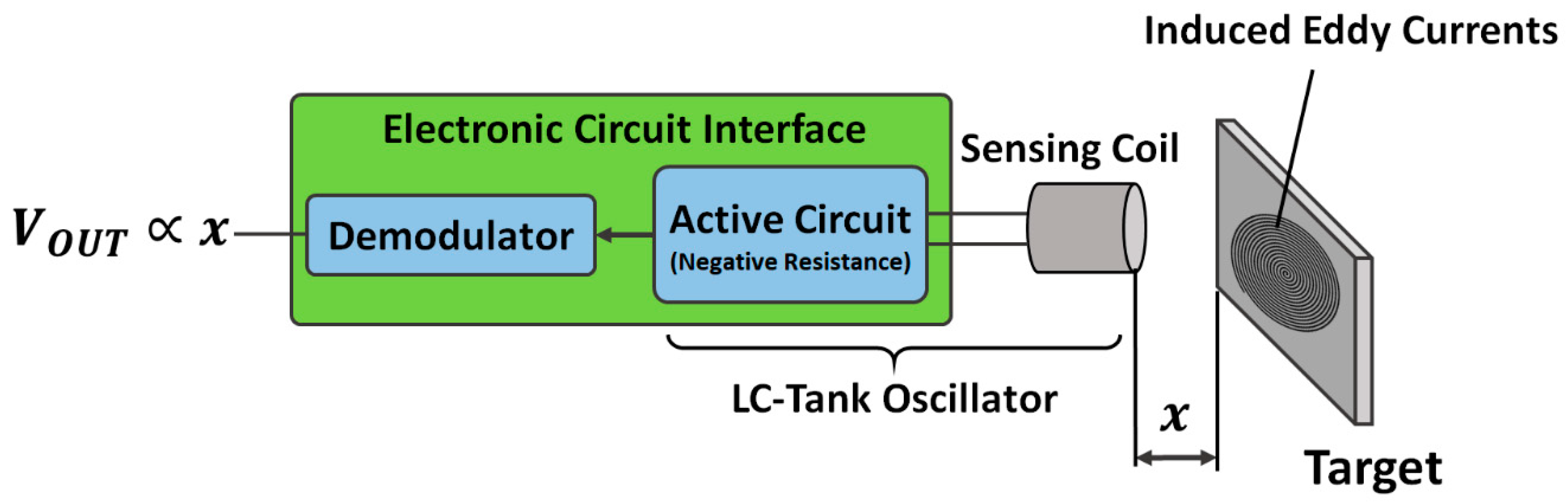
The block diagram of the proposed solution is shown in Figure 1. The main components of the realized ULP-ECDS are a conductive target, a sensing coil, and an ad hoc designed Electronic Circuit Interface (ECI). The combination of sensing coil and active circuit operating results in an LC-tank oscillator. The LC-tank oscillator signal is opportunely demodulated in order to obtain an output voltage of the ECI that is proportional to the distance x between the sensing coil and target.
In more detail, the realized prototype works on the principle of electromagnetic coupling between a sensor coil and the metal target to be detected. The sensing coil, driven by an ad hoc AC current, generates an alternating magnetic field. When the metal target enters the electromagnetic field induced by the sensing coil, some of the electromagnetic energy is transferred into the metal target. This transferred energy induces eddy currents. The eddy currents flowing in the metal target induce a reverse electromagnetic field on the sensing coil, causing magnetic flux reduction and energy dissipation in the sensing coil itself.
The macroscopic effect of this mechanism is that a change in the distance between the sensing coil and the target induces a variation in the total impedance of the sensing coil. This variation can be measured with a custom ECI. In more detail, when increasing the distance between the sensing coil and the target, the resistance of the sensing coil decreases, while the inductance increases. Vice versa, when the distance between the sensing coil and target diminishes, the resistance of the sensing coil increases, while the inductance decreases. The variation of the impedance of the sensing coil is non-linear over a large displacement range, affecting the effective measurement range of the sensor. As shown in the following, the material target also has a non-negligible effect on the measurement range.
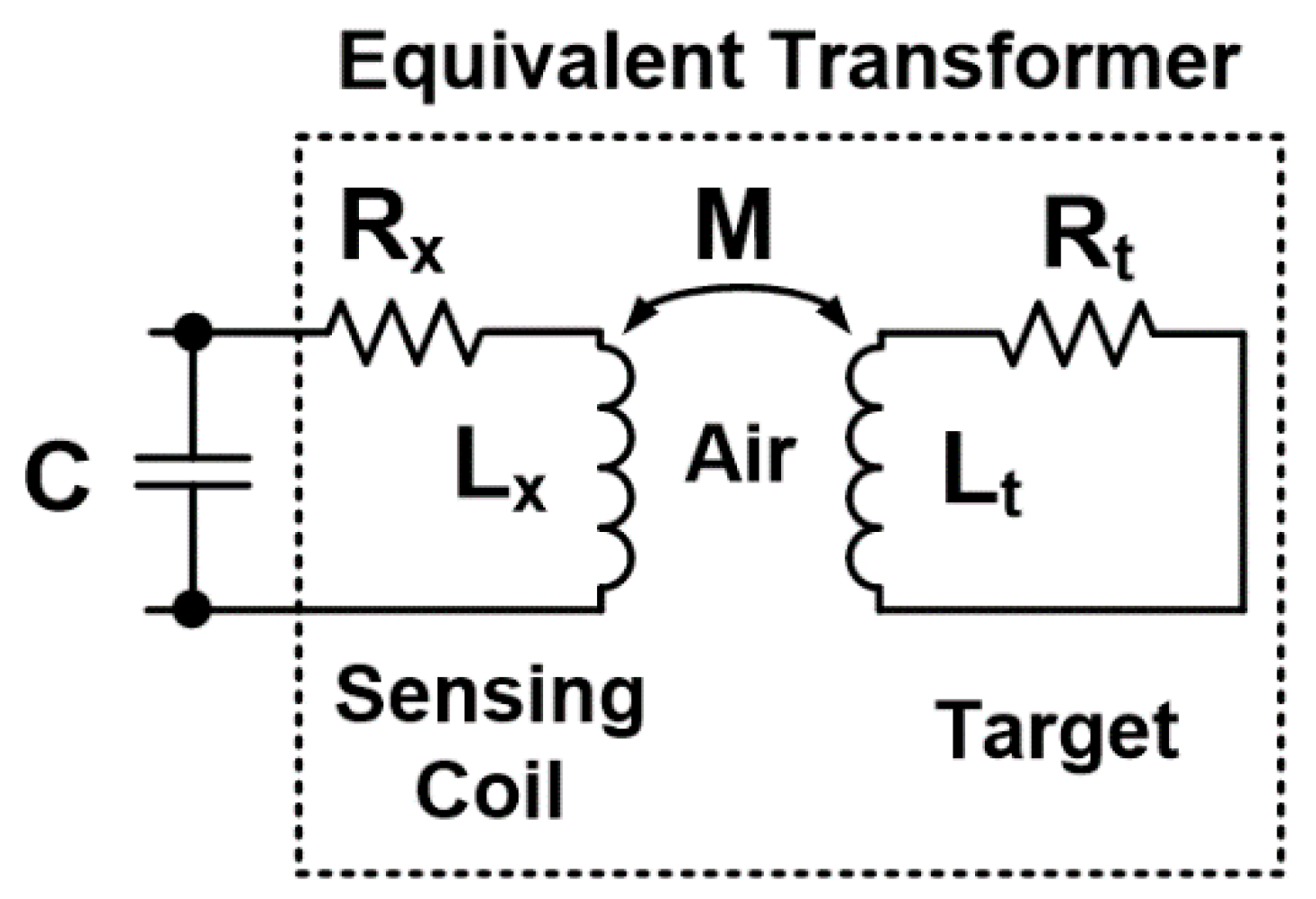
The coil–target air coupling can be considered as an equivalent transformer, as shown in Figure 2. The primary of the transformer is the sensing coil and is comprises the inductor Lx and the series resistor Rx. The secondary of the transformer, in which the eddy current flows, is comprises Lt and Rt, representing the target.
Simply by adding a capacitance C in parallel to the sensing coil Lx, it is possible to form the LC-tank oscillator needed to generate the alternating magnetic field, which in turn induces the eddy currents in the target. The capacitor C also includes the parasitic capacitance of the sensing coil. The closer the target moves to the sensing coil, the larger the damping of the oscillation amplitude generated by the LC-tank oscillator becomes. This is because eddy currents dissipate energy, producing an increase of Rx. In order to guarantee the proper operation of the LC-tank oscillator, an active circuit acting as a negative resistance is needed. It holds the oscillation stable by restoring the power losses in the LC-tank because of the change in Rx due to the x variations.
A change of x results in the variation of the equivalent sensor impedance, Zeq = Zx // C, where Zx = Rx + jωLx. The relationship between Zx and the target position x depends on the characteristics of the sensing coil, on the working frequency, and on the properties of the target. As described in [17], this can be summarized by (1):
where Rc and Lc are the nominal resistance and inductance of the sensing coil, respectively, while Re and Le are, respectively, the contributions of resistance and inductance caused by the eddy currents.
Zx = Rx +jωLx = [Rc + Re(x,σ,µ,f)] + jω[Lc + Le(x,σ,µ,f)],
2.2. Ultra-Low Power Electronic Circuit Interface
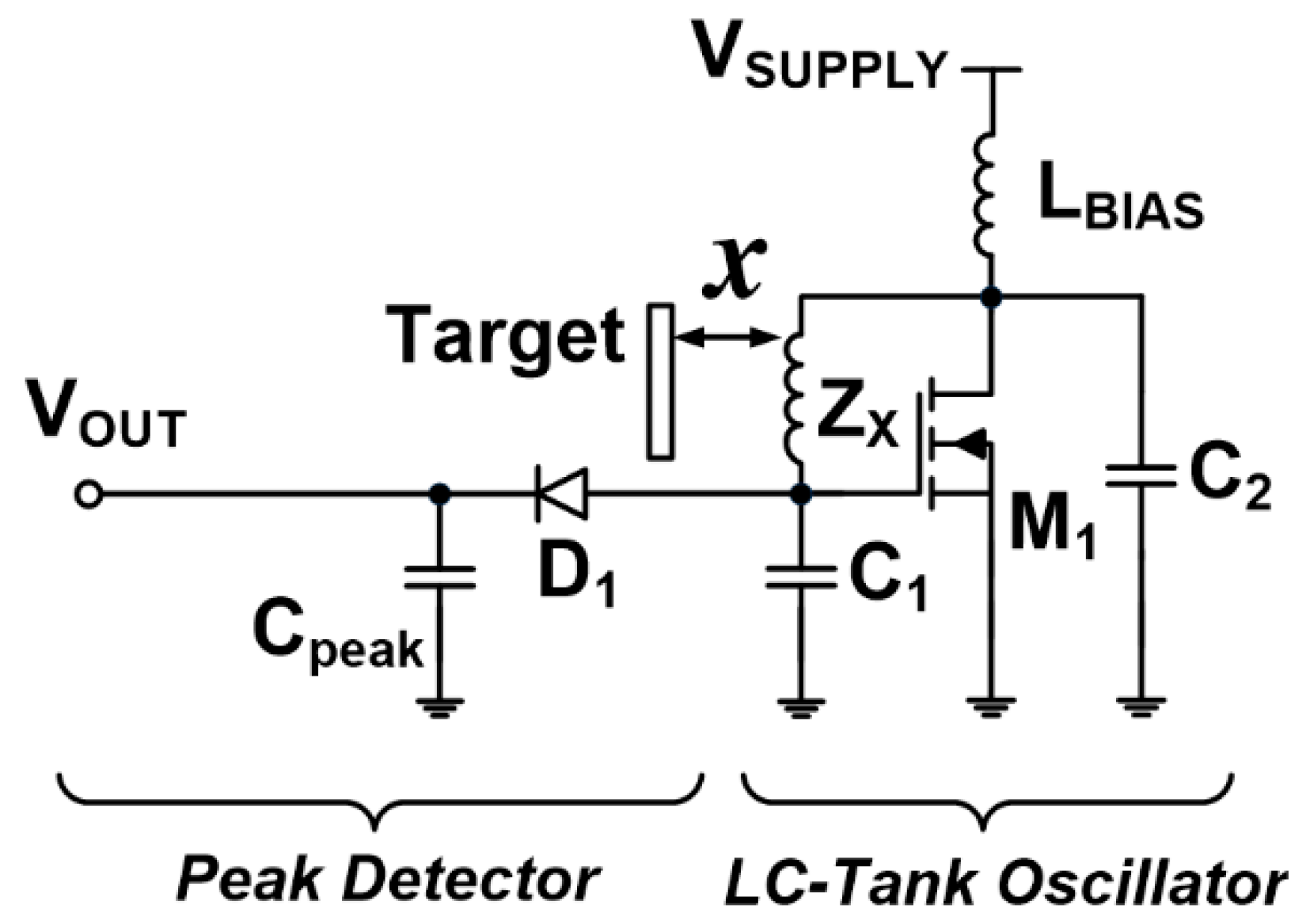
The realized ultra-low power ECI is shown in Figure 3. It combines an LC-tank oscillator with a peak detector, providing an output voltage proportional to the distance between the sensing coil and the target.
With reference to Figure 3, it is possible to note that the LC-tank is based on a Pierce oscillator-based configuration. The circuit comprises an active device M1, a passive network Zx, the capacitances C1 and C2, and the inductor Lbias operating as a constant current source and biasing the circuit.
The key component of the circuit is M1. It should have high forward transconductance, gm, and high output conductance at very low supply voltages, allowing for lowering the overall power consumption of the circuit. This also allows for ensuring the validity of the Barkausen’s criteria needed for a proper oscillation of the LC-tank. Among the commercial off-the-shelf components available on the market, a zero threshold MOSFET ALD212900 from Advanced Linear Devices, Inc. (Sunnyvale, CA, USA) was chosen.
In more detail, the LC-tank oscillator is able to operate properly with ultra-low input supply voltages, VSUPPLY, in the range 50–200 mV and it can be driven by a low-frequency AC excitation signal. Both these features of the ECI contribute to the power consumption minimization of the sensor.
To guarantee a stable oscillation with good performance in terms of the power consumption, resolution, and sensitivity of the sensor, it is necessary to increase the quality factor of the sensing coil, defined as Q(x) = ωLx/Rx. The Q factor depends on the displacement, x, because both Lx and Rx are functions of x, as summarized in (1). The higher the value of Q, the higher the accuracy and the stability of the oscillation. For this reason, a radial 10 mH 22R106C from Murata (Kyoto, Japan) was chosen as sensing coil Lx. The other components used to realize the LC-tank oscillator are C1 = 100 pF and C2 = 10 nF. Finally, a 68 mH (13R686C, Murata, Kyoto, Japan) was used as LBIAS.
Concerning the extraction of the displacement information, several demodulation techniques have been proposed in the recent literature for ECDSs. The most common ones are based on simultaneous peak sampling, peak detector, synchronous demodulation, Frequency Modulation (FM), Amplitude Modulation (AM), phase detection, and balanced bridge (e.g., [14,17,24]).
The basic operating principles of these solutions can be summarized in two main possible approaches. The first one allows for obtaining the displacement/position from the amplitude of the LC-tank oscillation, which in turn is related to the variation of the real term of the equivalent resistance of the sensing system resulting from the interaction between the sensing coil and target (i.e., AM demodulators). The second one allows for obtaining the displacement/position from the variation of the oscillation frequency of the LC-tank and it is related to the variation of the equivalent inductance of the sensing system (i.e., FM demodulators).
As described in the next section, the choice of the most suitable demodulation technique depends on both target-related design constraints and application-specific constraints (e.g., power consumption and resolution).
Since the proposed solution targets smart wireless sensor nodes for IIoT and Industry 4.0 applications (e.g., the measurement of the axial movement or the concentricity of roller shafts in automatic machinery or conveyor belts), the power consumption minimization of the ECDS has been considered as a key design constraint, with resolutions in the order of a few micrometers being acceptable for the considered applications. For these reasons, an AM demodulator was chosen. Indeed, compared with other typologies, basic AM demodulators rely on simpler circuits, resulting in reduced power consumption.
With reference to Figure 3, among the possible AM demodulators, a simple stand-alone peak detector, comprising a classic diode D1 = 1N4148 and Cpeak = 10 nF, was implemented. The oscillation amplitude demodulation was obtained by connecting the peak detector at the gate terminal of M1. The output signal of the negative gm LC-tank oscillator circuit, indeed, is an analog voltage, and its amplitude is directly related to the displacement x.
The ECI of the realized ULP-ECDS was designed to obtain an LC-tank operating with a very low oscillation frequency f (i.e., <140 kHz) to further reduce the power consumption of the sensor.
Since an AM modulator is used, indeed, there is no need to drive the LC-tank with high frequency AC signals, because the displacement information is extracted from the amplitude of the oscillation, not from its frequency shift caused by the inductance shift of the sensing coil (maximized by high-frequency oscillations).
As shown by the experimental results presented in a subsequent section, the chosen mix of circuit architecture and components allowed for obtaining a sensor with a resolution of a few micrometers and a power consumption ranging from a few microwatts to less than 150 µW (depending on VSUPPLY), which is noticeably lower than the ones of other state-of-the-art solutions (ranging from a few milliwatts to hundreds of milliwatts).
3. Design Considerations
Targeting wireless devices, the power consumption minimization is the most important issue to obtain effective solutions in real applications. In the case of battery-powered devices, indeed, it allows for achieving an acceptable replacement rate and, at the same time, represents the first step towards the realization of a new generation of self-powered sensors able to gather the energy needed for their proper operation directly from the environment where they operate. Of course, this is possible only by combining the sensor with ad hoc designed energy-harvesting systems.
As mentioned before, the solution proposed in this paper relies on an AM demodulator able to work properly with ultra-low supply voltages (i.e., <200 mV) and a LC-tank oscillator operating at low frequencies (i.e., <140 kHz vs. tens of MHz of other state-of-the-art solutions proposed in the literature). Thanks to these unique features, a significant power consumption reduction was obtained, reaching a resolution and sensitivity suitable for a wide range of industrial applications.
As an additional benefit, in the first approximation, the extremely low-power consumption allows for neglecting the effects of the thermal drift, which are considered the main drawback of ECDSs. Indeed, it is at least two orders of magnitude lower than the threshold of 20 mW, indicated in [23] as the maximum power consumption needed to obtain measurements not affected by errors due to thermal issues.
The choice of the most suitable demodulation technique to extract the displacement information is strictly application dependent and there is not a best solution a priori, because the design of an ECDS is the result of trade-offs among different application-specific constraints.
From one side, the recent literature shows that FM demodulators allow for obtaining the best resolution (even sub-nanometric), but they require both an LC-tank oscillator operating at a very high frequency and complex and power-hungry circuits relying on frequency-to-voltage converters.
FM demodulators, indeed, extract the displacement information from the measurement of the frequency of the LC-tank oscillator that is in charge to generate the AC signal needed to induce the eddy currents in the target. The variation of distance between the target and sensing coil causes a variation of the inductance of the sensing system that in turn causes the variation of the frequency of the LC-tank oscillator. By using proper frequency-to-voltage converters, it is possible to measure the frequency shift, obtaining the desired displacement information.
To obtain the best performance, they need to maximize the sensor inductance shift response to a change in the distance between the sensing coil and target by maximizing the eddy currents induced in the target. The higher the oscillation frequency, the larger the shift of the inductance of the sensor which occurs when the distance between the sensing coil and target changes, and consequently the sensitivity of the sensor improves.
A high oscillation frequency also contributes to the reduction of the effects of the target material on the performance of the sensor, allowing for using both non-magnetic and ferromagnetic materials, contributing to the widening of the application fields of the sensor itself. In general, the higher the oscillation frequency, the smaller the skin depth, allowing for concentrating the eddy currents on the target surface. For example, in the case of ferromagnetic materials like carbon steel, the skin depth at high frequencies (i.e., >10 MHz) becomes small enough that the generated eddy currents prevent the magnetic field lines from entering the metal. From a practical point of view, this means that, at high frequency, a ferromagnetic material presents an inductance shift consistent with other non-magnetic materials (e.g., copper and aluminum), nevertheless, its lower conductivity allows for using FM demodulators with good performances. Conversely, working at very high frequencies forces the use of high-frequency electronic circuits that are very power-consuming. Of course, this is in contrast with the power consumption minimization, which is a typical design constraint for sensors targeting battery-powered or self-powered devices (e.g., autonomous sensors embedded in energy harvesters for IIoT applications).
On the other side, AM demodulators, instead, extract the displacement information by measuring the amplitude of the LC-tank oscillation that is directly related to the eddy current losses that the LC-tank must compensate for in response to the variation of displacement between the target and sensing coil. These losses are always present in ECDSs and are mainly due to the change in the Rx terms of (1).
AM demodulators usually exploit simpler circuits, allowing for reducing the power consumption, at the cost of lower resolution and sensitivity, at least in their basic configurations. High-performance AM demodulators have been presented, but once again they require complex functional blocks operating at high frequency (e.g., sample and hold and ADC converters) that lead to an overall power consumption comparable with the ones of FM demodulators.
Since AM demodulators extract the displacement information from the amplitude variation of the LC-tank oscillation, it is possible to design LC-tank oscillators operating at low resonance frequencies. While this is beneficial for the power consumption (i.e., simpler electronic circuits), this limits the application fields of the sensor because, when operating at low frequencies, the effects of the target on the performance of the sensor are not negligible, as demonstrated by the characterization carried out on the realized ULP-ECDS and presented in the following section. In particular, three different materials with different magnetic and electrical properties and commonly used in industrial applications were considered. They are carbon steel, copper, and aluminum.
In many real applications, the target must be considered as a design constraint rather than a degree of freedom and its effects must be taken carefully into account during the design of an ECDS because they guide the designer in the choice of the most suitable demodulation technique to extract the displacement/proximity information. The proposed ULP-ECDS, indeed, achieves the best performance when used in combination with the carbon steel target, although it is a ferromagnetic material and has the worst electrical properties among the three considered ones.
To achieve the best performance, sensors based on FM demodulators require the use of targets that should ideally have conductivity, σ, as high as possible and permeability, μ, as low as possible. High σ allows for reducing the electrical resistance of the target and amplifying the eddy current induction, while low μ allows for reducing the magnetic reluctance that operates in the opposite direction with respect to the eddy currents. For these reasons, non-ferromagnetic materials, such as copper or aluminum, are preferred as target materials for this kind of demodulator.
Unfortunately, ferromagnetic materials like steel or carbon steel are very common in many industrial applications, and often, due to application-specific constraints, the designer is forced to design an ECDS considering a target made of these materials. Steel and carbon steel have a much lower conductivity than copper and aluminum and consequently the amount of eddy currents generated on the target surface is reduced. This causes a reduced inductance shift, especially for lower values of LC-tank oscillation frequencies, which limits the measurement resolution in the case of the use of an FM demodulator.
Therefore, AM demodulators can be a better choice when ferromagnetic targets must be used, because, as mentioned before, the extraction of the displacement information is based only on the amplitude of the LC-tank oscillation frequency. This is related to the eddy current losses that the LC-tank must compensate for to guarantee a stable oscillation in response to a change in the distance between the target and sensing coil, and they are always present.
Choosing the right ECI accordingly with the target is mandatory to obtain an effective solution, especially in the case of sensors designed to be embedded in battery-powered devices, where the minimization of the power consumption is the main design challenge.
4. Measurement Setup
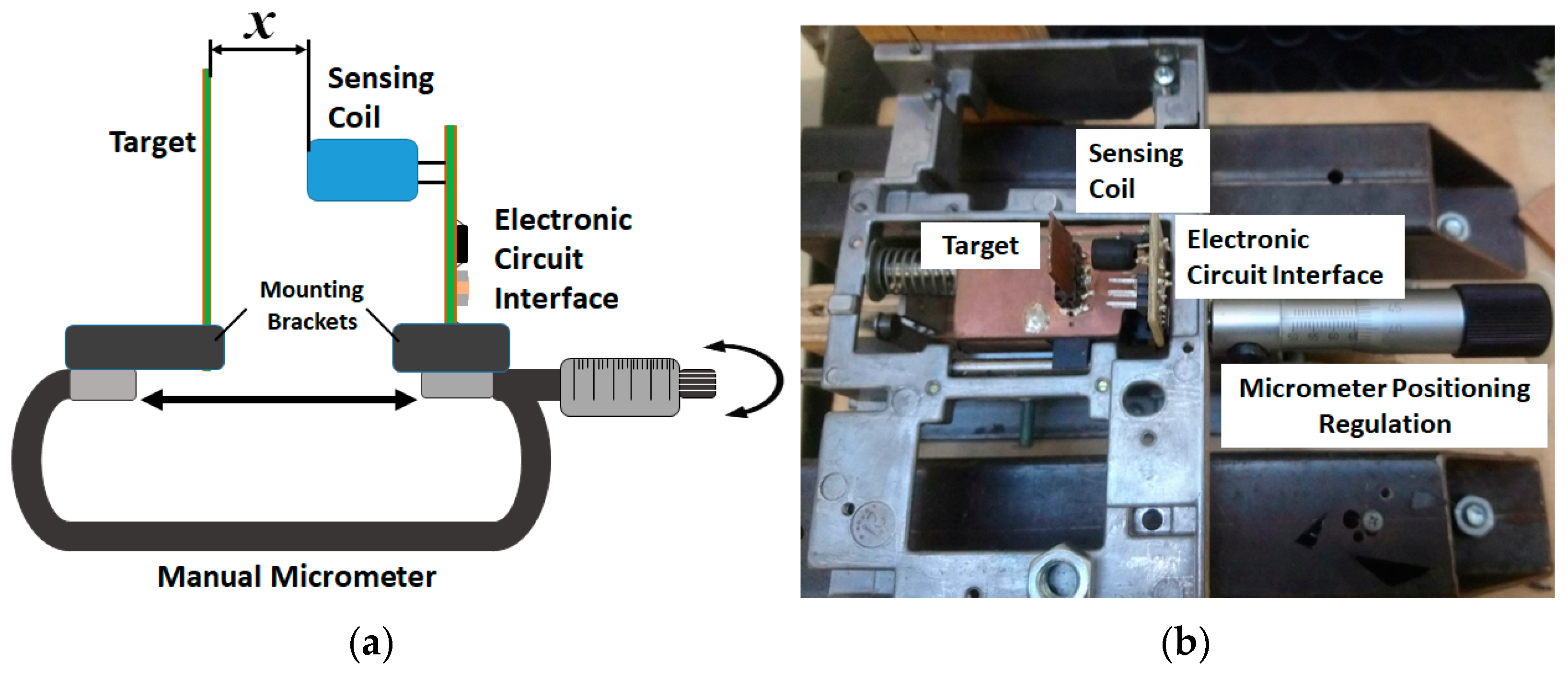
All the tests were carried out by exploiting the setup sketched in Figure 4a. The implemented ECI was fixed by means of a mounting bracket to the fixed end of a commercial manual outside micrometer, while the target was positioned on its own mounting bracket fixed to the moving end of the micrometer. In this way, the distance between the target and sensing coil can be varied by micrometers in a repeatable way. It is important to note that the initial point x = 0 µm of the considered measurement range corresponds to an absolute distance between the sensing coil and the target of 500 µm. This allowed for reproducing more realistic working conditions that occur in real industrial applications, where the ECDSs are used for contactless measurements. With reference to Figure 3, the ECI’s output voltage, VOUT, and the frequency of the LC-tank, f, were measured by means of a Keysight DSO9254A oscilloscope (Keysight, Santa Rosa, CA, USA).
The EIC’s supply voltage, VSUPPLY, was provided by a high- N6784A DC Power Analyzer (Keysight, Santa Rosa, CA, USA) module to also precisely measure the current and power consumption of the realized sensor. In order to limit any thermal drift issues, all the tests were carried out at the same temperature (Troom ~ 23 °C).
5. Experimental Results
This section presents the results obtained from the complete characterization of the proposed solution when operating in combination with different metallic targets. The considered targets were made of aluminum, copper, and carbon steel. All the considered targets had an active area of 15 mm x 15 mm, larger than the 6 mm diameter of the radial inductor used as a sensing coil to guarantee the strongest response of the target. Thicknesses of 1 mm and 2 mm were considered to reproduce common working conditions for industrial applications.
For each considered target, the analog output voltage of the sensor, VOUT, the frequency of the LC-tank oscillator, f, and the overall power consumption of the whole system, PSUPPLY, were measured. The tests were carried out for displacement x in the range 0–5 mm and for different values of ECI’s supply voltage, VSUPPLY.
5.1. Preliminary Tests
A preliminary test to evaluate the influence of the different targets on the sensing system was carried out by exploiting the setup described in the previous section. In particular, the sensing coil was disconnected from the ECI of the realized ULP-ECDS and was connected to an E5071C Network Analyzer from Agilent Technologies.
For each target, S11 measurements were carried out at the terminals of the sensing coil with the target positioned at different distances x within the considered 0–5 mm range and the corresponding values obtained at frequencies within the operating range of the LC-tank oscillator were averaged (i.e., 125 kHz ≤ f ≤ 140 kHz, as shown in the following subsections).
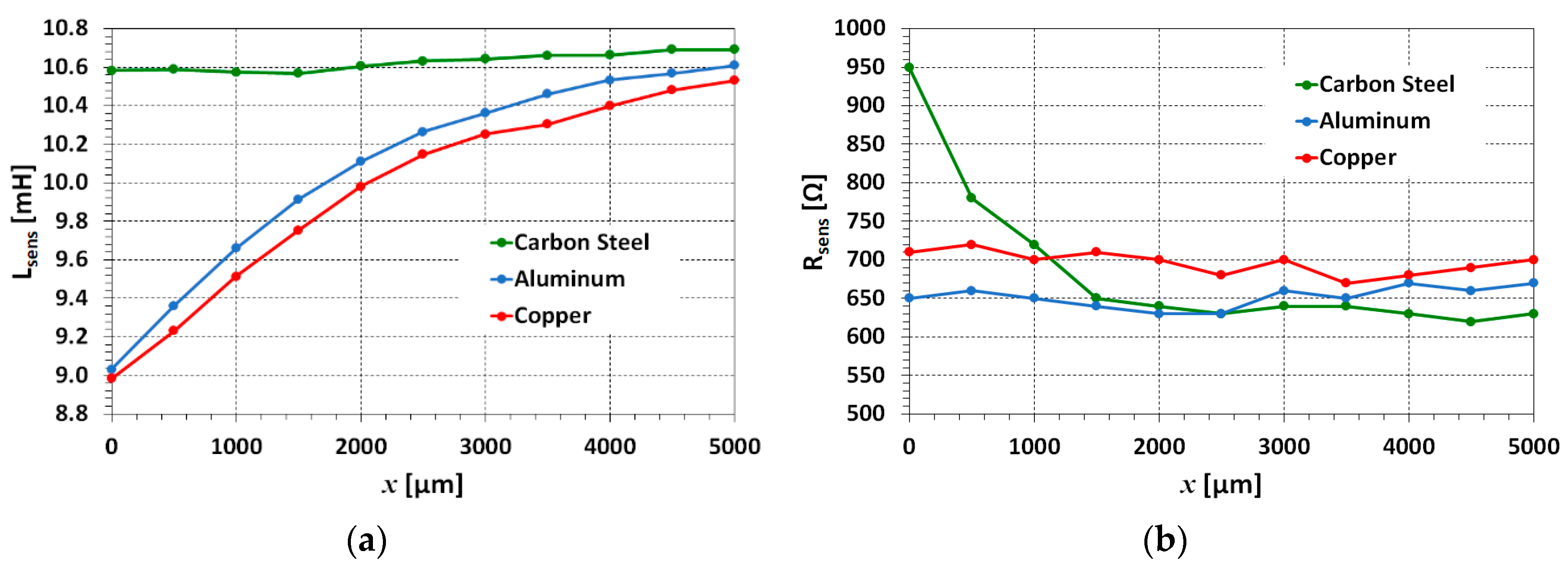
Both the inductance, Lsens, and the resistive term, Rsens, of the whole sensing system (i.e., the sensing coil interacting with the target) were extracted from the S11 measurements. The results referring to 1 mm thick targets are shown in Figure 5. Very similar results were also obtained in the case of 2 mm thick targets.
With reference to Figure 5a, it is possible to note that, in the frequency range of interest, the inductance shift generated in the sensing coil by the interaction with the target is larger in the case of the aluminum and copper targets, while it is negligible in case of the carbon steel target. Figure 5b, instead, shows that the variation of the resistive terms is much more evident in the case of the carbon steel target, and especially for small distances of x, i.e., when there is the maximum interaction between the sensing coil and target.
This confirms the initial hypothesis that the target has non-negligible effects on the performance of an ECDS and must be taken into account during the sensor design. In more detail, the reduced inductance shift in the case of the carbon steel target is due to: (i) the lower conductivity of carbon steel compared with that of copper and aluminum and (ii) the effects of its ferromagnetic properties. In general, the greater the inductance shift, the greater the variation of the LC-tank oscillation frequency, corresponding to a variation of distance between the sensing coil and target. From a practical point of view, this suggests that aluminum and copper are preferred target materials when the ECDS is based on FM demodulators, i.e., circuits mainly based on frequency-to-voltage converters to extract the displacement information.
Vice versa, the largest variation in the resistance occurs when the sensing coil interacts with the carbon steel target. This suggests that when a ferromagnetic target must be used, a more effective ECDS solution should rely on AM demodulators (i.e., displacement information extracted from the amplitude variation of the LC-tank oscillation signal).
5.2. Output Voltage
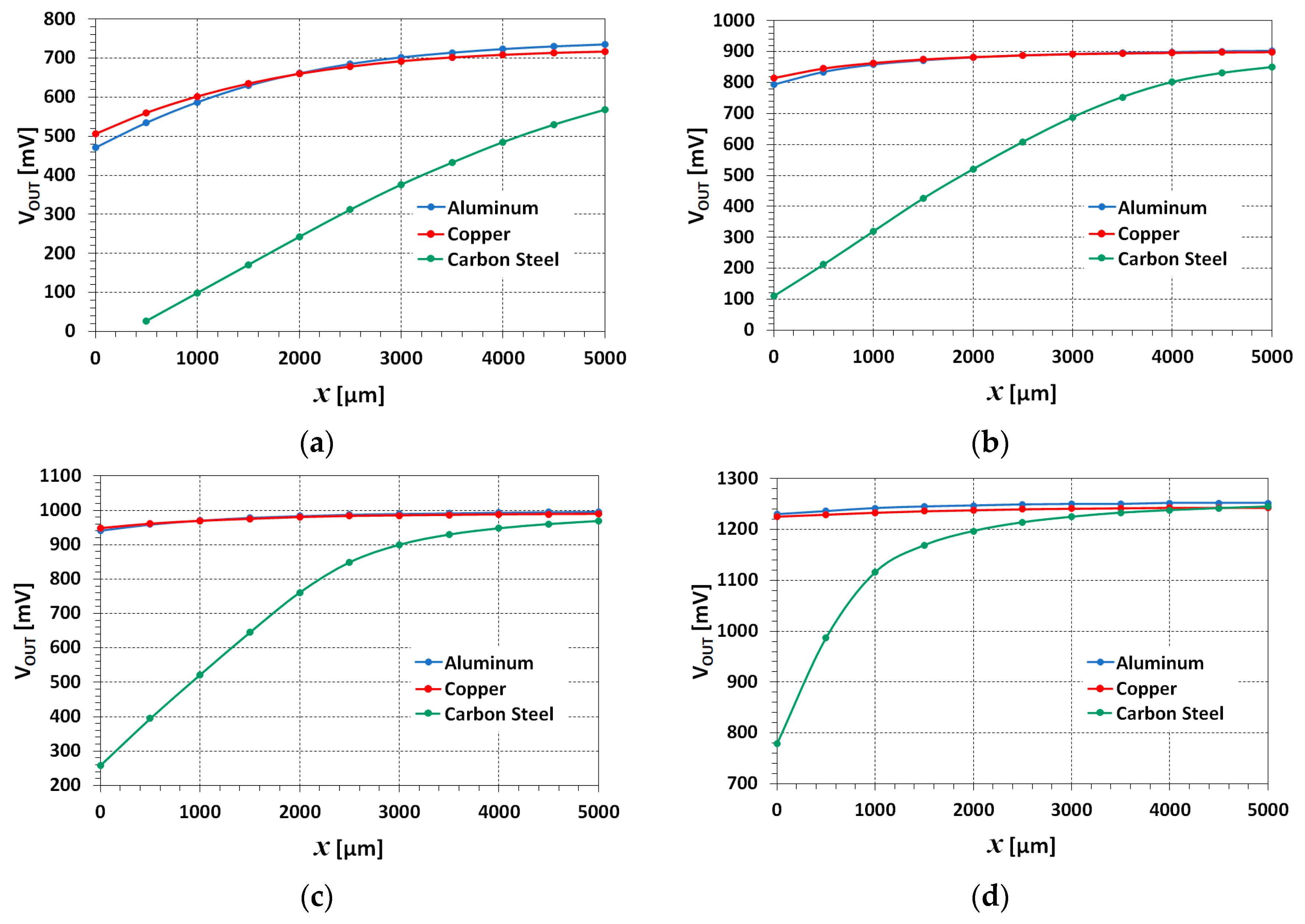
The measured output voltages, VOUT, of the realized ULP-ECDS when the sensing coil operated in combination with 1mm thick targets made of the three considered materials are shown in Figure 6.
As expected by the results obtained by the S11 measurements of the preliminary test, the realized sensor presents a different behavior depending on the target and on the ECI’s supply voltage, VSUPPLY. Copper and aluminum are non-magnetic materials with very similar properties and therefore present the same behavior: the larger the VSUPPLY, the lower the slope of VOUT. This corresponds to a reduced total output voltage variation over the measurement range and, consequently, reduced sensitivity and resolution.
This is due to the chosen AM demodulator. Indeed, as shown in Figure 5, the interaction of the sensing coil with copper and aluminum targets produces significant inductance shifts, but negligible variations of the resistance of the whole sensing system, causing a limited variation of the amplitude of the LC-tank oscillation.
The opposite behavior occurs when the sensing coil interacts with the carbon steel target: the larger the VSUPPLY, the larger the total output, VOUT, variation over the measurement range.
As shown in Figure 5, the interaction between the carbon steel target and the sensing coil produces a larger variation of the resistance of the sensing system. This in turn causes a larger variation of the amplitude of the LC-tank oscillation, resulting in a larger VOUT in output from the demodulator (i.e., in output from the sensor) that is beneficial for the performance of the sensor.
The closer the target moves to the sensing coil, the larger the damping of the oscillation amplitude due to an increase in Rx in the sensing coil. The active circuit operating as a negative resistance generator guarantees the proper operation of the LC-tank oscillator (i.e., holding the oscillation stable) by restoring the power loss in the tank because of the change in Rx occurring when the distance between the sensing coil and target, x, changes. In this regard, it is possible to note in Figure 6 how the larger variations of VOUT occur in correspondence to the region in which the relationship between VOUT and x is linear, i.e., the one where there is the largest variation of Rx.
With reference to Figure 6a, it is possible to also note that, in the case of the carbon steel target and VSUPPLY = 50 mV, the sensor provides a stable VOUT starting from a displacement of x = 500 µm. As mentioned before, this occurs because the closer the target is to the sensing coil, the larger the eddy currents that are induced on the target surface, and the larger the power losses that must be compensated by the LC-tank oscillator to keep a stable oscillation. But the lower the VSUPPLY, the lower the power available for the LC-tank oscillator, and if it is not enough, the LC-tank oscillator is no longer able to sustain the oscillation.
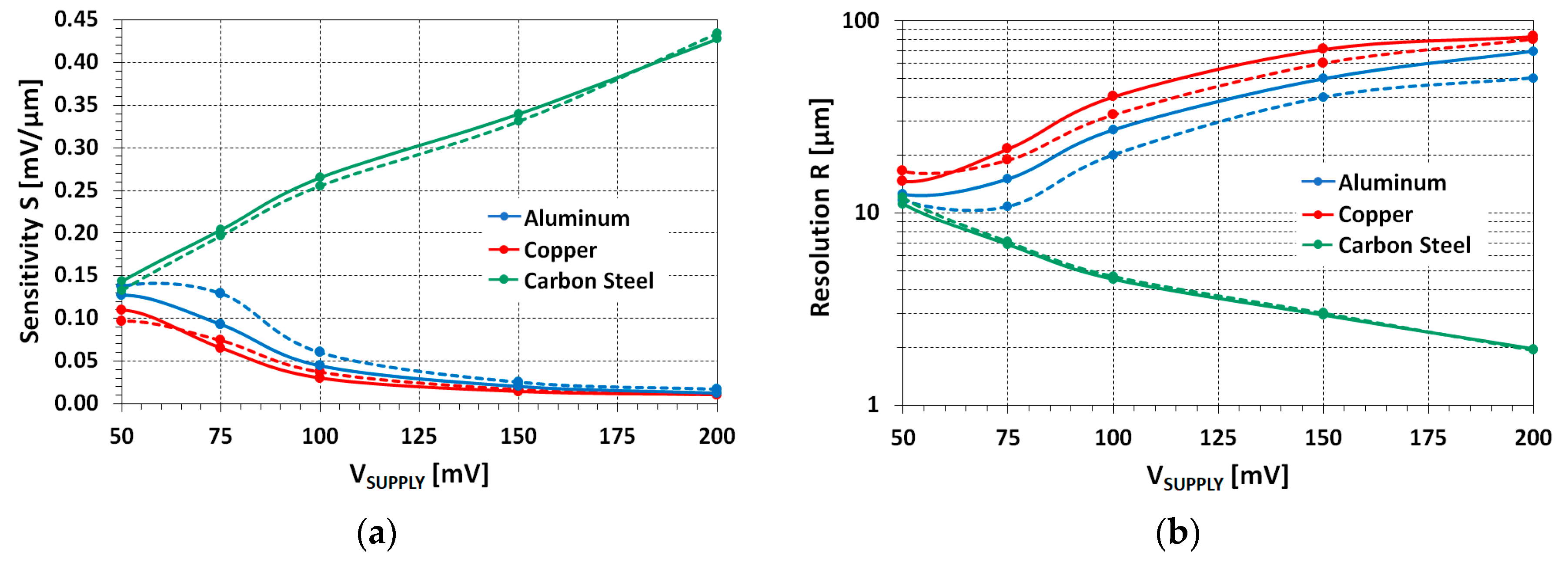
The same trends and very similar results were also obtained with targets 2 mm thick. The slight differences are highlighted in Figure 7, which shows the results of sensitivity, S, and resolution, R, calculated for different values of VSUPPLY and different target thicknesses.
By defining ∆x as the interval in which the relationship between VOUT and x is linear, and ∆VOUT the difference between the values of VOUT measured at the upper end and lower end of the interval ∆x, respectively, it is possible to define the sensitivity of the realized sensor, S, by (2):
where S is expressed in mV/µm.
S = ∆VOUT/∆x
By exploiting S, the resolution of the realized sensor, R, can be expressed in µm by (3):
where N, with regard to the measurement setup, is the measured RMS channel noise of the oscilloscope.
R = N/S,
In agreement with the results shown in Figure 6, the best performances were obtained with the carbon steel target. In this case, the larger the VSUPPLY, the higher the sensitivity, S, of the sensor, and the better the resolution, R, but the interval ∆x is lower where the relationship between VOUT and x is linear (i.e., the effective measurement range of the sensor is lower).
On the contrary, the performance of the sensor worsens as VSUPPLY increases in the case of the aluminum and copper targets. Once again, it is related to the operating principle of the realized sensor that is based on the extraction of the displacement information from the amplitude of the LC-tank oscillation signal and not from its change in frequency caused by inductance shifts.
5.3. LC-tank Oscillation Frequency
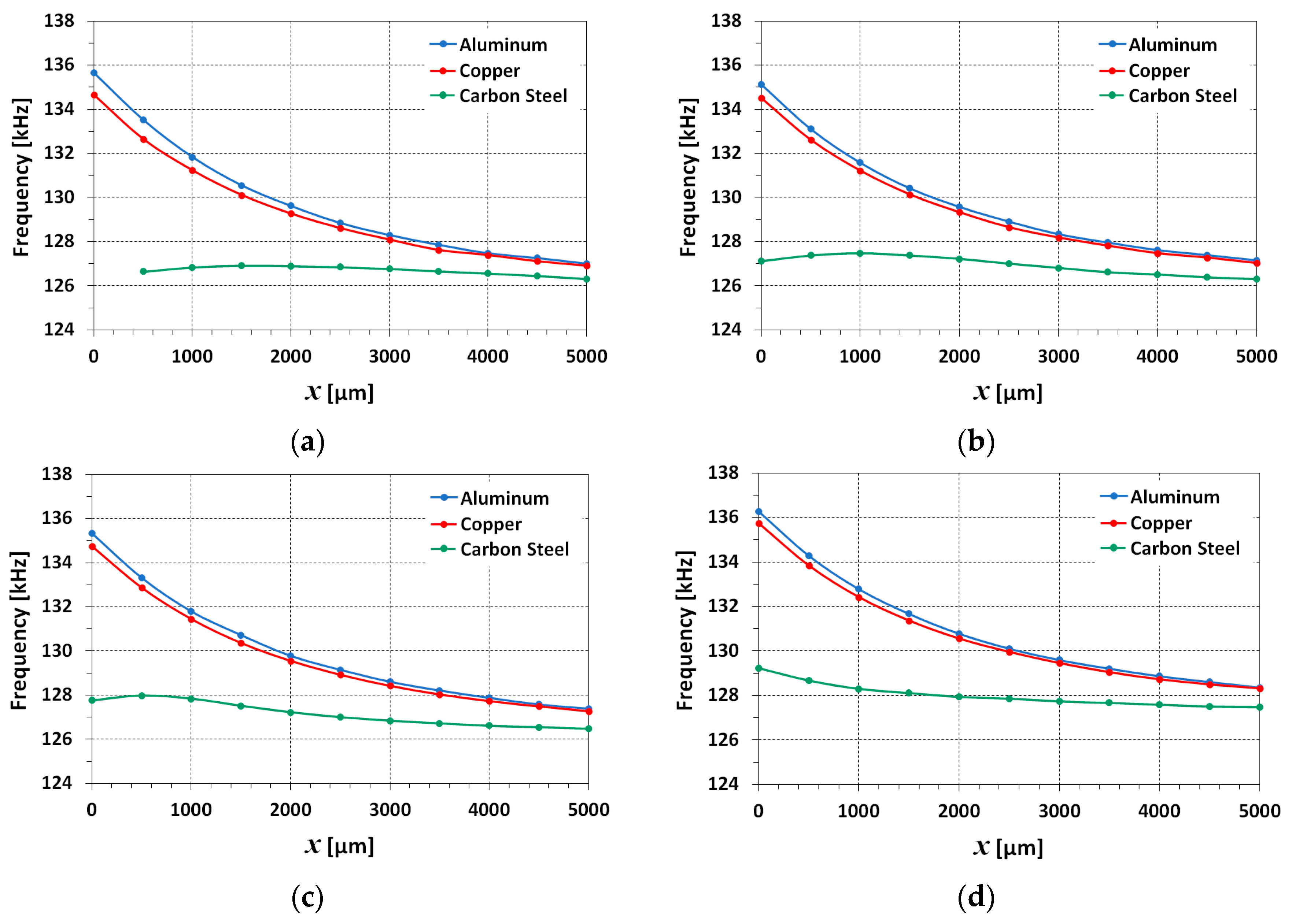
The effects of the interaction between the realized sensor and the different targets were also evaluated by measuring the oscillation frequency of the LC-tank oscillator, f, over the considered displacement range, and for different values of VSUPPLY. The obtained results are shown in Figure 8. They refer to 1mm thick targets, as differences smaller than 1% were observed in the case of 2 mm thick targets.
As it is possible to note, there is a very different behavior of the sensor when it interacts with the different materials. The effects of the carbon steel targets are negligible on the frequency of the LC-tank oscillation. In general, for a given VSUPPLY, the frequency variations are very limited (less than 1 kHz) and are concentrated at small values of x, i.e., where the interaction between the sensing coil and target is stronger.
As also confirmed by the results shown in Figure 5a, the total equivalent inductance of the sensing system coil with the carbon steel target is almost constant and higher than the ones obtained in the case of aluminum and copper targets. This is due to the ferromagnetic properties of the carbon steel, which also led to a lowering of the resonant frequency of the LC-tank circuit.
With aluminum and copper targets, instead, the effects of the interaction between the target and sensing coil are more evident in the LC-tank oscillation frequency. As it is possible to note, the larger the distance between the sensing coil and target, the lower the LC-tank oscillation frequency, because of the increment in the inductance, in agreement with the S11 measurements carried out (see Figure 5). In terms of absolute values, the differences between the two targets are very small because copper and aluminum are materials with very similar properties.
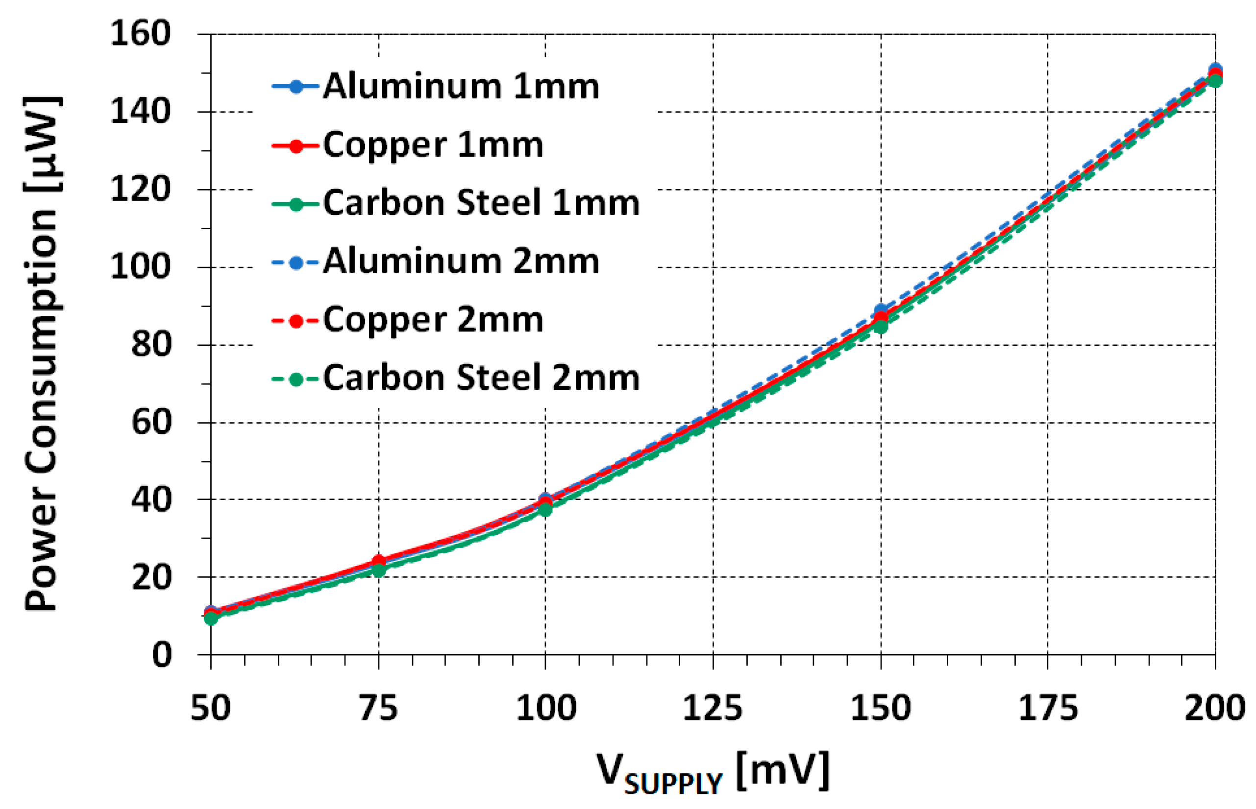
5.4. Power Consumption
The characterization of the sensor was completed by measuring the power consumption of the realized ULP-ECDS. The obtained results are shown in Figure 9. As expected, it is possible to note that the power consumption depends only on VSUPPLY, and it is not influenced by the material or the thickness of the target.
Noticeably, the obtained power consumption ranges from 10 µW to 150 µW, which is at least two orders of magnitude lower than the power consumption of state-of-the-art solutions presented in the recent literature.
6. Performance Analysis and Discussion
The ultra-low power consumption of the realized ULP-ECDS was obtained by combining a LC-tank oscillator operating at low frequencies (i.e., <140 kHz vs. tens of MHz of other state-of-the-art solutions proposed in the literature), with an AM demodulator able to work properly with very low supply voltages (i.e., <200 mV).
Under these working conditions, the effects of the target on the performance of the sensor are not negligible, as demonstrated by the experimental results. The proposed ULP-ECDS, indeed, achieves the best performance when used in combination with the carbon steel target, although it is the material with the worst electrical properties among the three considered ones.
Carbon steel has a lower conductivity than copper and aluminum and, consequently, the amount of eddy currents generated on the target surface is reduced. As shown by the S11 measurements, this causes a reduced inductance shift, especially for lower values of the LC-tank oscillation frequency. This generally limits the measurement resolution in the case of the use of frequency-to-voltage converters (FM demodulators) to extract the displacement information. In the proposed solution, instead, the displacement information is extracted by the analog demodulation of the LC-tank oscillation frequency amplitude. The variation of the amplitude is caused by the variation of the resistance of the sensing system, in response to the variation of distance between the sensing coil and target. In the considered LC-tank frequency range, due to its ferromagnetic properties, the carbon steel target affects mainly the resistance of the sensing system with negligible effects on the inductance.
Vice versa, the interaction of the sensor with copper and aluminum targets produces negligible variations in the resistance of the sensing system in response to a variation of distance between the sensing coil and target, and a more significant shift in the inductance of the sensing system.
From a practical point of view, this confirms that in the case of use of non-magnetic targets, a more effective solution should be based on FM demodulators, at the cost of a significant increase in the power consumption. On the contrary, when there are stringent design constraints in terms of power consumption or the use of ferromagnetic targets are mandatory, AM demodulators should be considered in the design of the ECDS.
From the experimental results presented in the previous section, indeed, the best performances of the sensor were obtained when it operated in combination with the carbon steel target.
Table 1 summarizes the performance of the realized ULP-ECDS in the case of interaction with the carbon steel target. The data were obtained by combining the results of Figure 7 (resolution) and Figure 9 (power consumption), and they refer to 2 mm thick targets, which is a more common value in several industrial components.
The results show that resolution and power consumption are opposite requirements in the case of the realized sensor operating with a carbon steel target. The better the resolution, the larger the power consumption. For the proposed solution, the best trade-off condition between resolution and power consumption corresponds to VSUPPLY = 100 mV, as highlighted in Table 1. As it is possible to note, indeed, when halving VSUPPLY (i.e., 50 mV), the power consumption drops from 37 µW to less than 10 µW at the cost of a resolution that passes from 4.7 µm to 12 µm, limiting the application fields of the sensors. Vice versa, when doubling VSUPPLY (i.e., 200 mV), the power consumption rises to about 150 µW, but the resolution reaches 2 µm.
The above considerations are also valid for 1 mm thick targets, as the differences in the measurements are negligible.
7. Conclusions
In this paper, a ULP-ECDS with power consumption in the range 10 µW–150 µW and a resolution of up to 2 µm was presented. The ultra-low power consumption was obtained thanks to the realized ECI, which is able to generate a stable low-frequency oscillation of the LC-tank by working properly with extremely low supply voltages (i.e., in the range 50–200 mV).
From an application point of view, the combination of the realized ULP-ECDS with modern low-power wireless microcontrollers (WMCUs) could result in a smart sensing system that can be powered by an embedded ad hoc energy-harvesting system, paving the way for the realization of a new generation of self-powered wireless displacement and proximity sensors for industrial applications.
The realized prototype was tested in combination with targets differing from each other in material and thickness. In many real applications, indeed, the target must be considered as a design constraint, rather than a degree of freedom. Therefore, its magnetic and electric properties must be carefully taken into account during the design of an ECDS because they guide the designer in the choice of the most suitable demodulation technique to extract the displacement/proximity information. This becomes even more important in the case of the design of ULP solutions, as demonstrated by the experimental results showing that the best performances were obtained when the sensor was used in combination with the carbon steel target, although it is the material with the worst electrical properties among the three considered ones.
Author Contributions
A.B. conceived the work, A.B, M.L., and G.S. developed the prototypes and performed characterizations and measurements. All the authors contributed equally to the writing of the manuscript. All authors have read and agreed to the published version of the manuscript.
Funding
This research received no external funding.
Conflicts of Interest
The authors declare no conflict of interest.
References
- Wang, K.; Zhang, L.; Han, B.; Chen, S. Analysis and Experiment of Self-Differential Eddy Current Displacement Sensor for AMBs Used in Molecular Pump. IEEE Trans. Instrum. Meas. 2018, 67, 1815–1824. [Google Scholar] [CrossRef]
- Bonfitto, A.; Gabai, R.; Tonoli, A.; Castellanos, L.M.; Amati, N. Resonant inductive displacement sensor for active magnetic bearings. Sens. Actuators A Phys. 2019, 287, 84–92. [Google Scholar] [CrossRef]
- Borovik, S.; Sekisov, Y. Single-Coil Eddy Current Sensors and Their Application for Monitoring the Dangerous States of Gas-Turbine Engines. Sensors 2020, 20, 2107. [Google Scholar] [CrossRef] [PubMed] [Green Version]
- Wu, J.; Wen, B.; Zhou, Y.; Zhang, Q.; Ding, S.; Du, F.; Zhang, S. Eddy Current Sensor System for Blade Tip Clearance Measurement Based on a Speed Adjustment Model. Sensors 2019, 19, 761. [Google Scholar] [CrossRef] [PubMed] [Green Version]
- Hu, P.; Zhao, L.; Tang, C.; Liu, S.; Dang, X.; Hu, Y. A New Method for Measuring the Rotational Angles of a Precision Spherical Joint Using Eddy Current Sensors. Sensors 2020, 20, 4020. [Google Scholar] [CrossRef] [PubMed]
- Johnston, D.P.; Buck, J.A.; Underhill, P.R.; Morelli, J.E.; Krause, T.W. Pulsed eddy-current detection of loose parts in steam generators. IEEE Sens. J. 2018, 18, 2506–2512. [Google Scholar] [CrossRef]
- Alatawneh, N.; Underhill, P.R.; Krause, T.W. Low-frequency eddy current testing for detection of subsurface cracks in CF-188 stub flange. IEEE Sens. J. 2018, 18, 1568–1575. [Google Scholar] [CrossRef]
- Stott, C.A.; Underhill, P.R.; Babbar, V.K.; Krause, T.W. Pulsed eddy current detection of cracks in multilayer aluminum lap joints. IEEE Sens. J. 2015, 15, 956–962. [Google Scholar] [CrossRef]
- Pereira, D.; Clarke, T.G.R. Modeling and design optimization of an eddy current sensor for superficial and subsuperficial crack detection in Inconel claddings. IEEE Sens. J. 2015, 15, 1287–1292. [Google Scholar] [CrossRef]
- Yamaguchi, T.; Ueda, M. An active sensor for monitoring bearing wear by means of an eddy current displacement sensor. Meas. Sci. Technol. 2007, 18, 311–317. [Google Scholar] [CrossRef]
- Wang, F.; Men, C.; Kong, X.; Meng, L. Optimum Design and Application Research of Eddy Current Sensor for Measurement of TBM Disc Cutter Wear. Sensors 2019, 19, 4230. [Google Scholar] [CrossRef] [PubMed] [Green Version]
- Lee, K.; Hao, B.; Li, M.; Bai, K. Multiparameter Eddy-Current Sensor Design for Conductivity Estimation and Simultaneous Distance and Thickness Measurements. IEEE Trans. Ind. Inform. 2019, 15, 1647–1657. [Google Scholar] [CrossRef]
- Li, W.; Ye, Y.; Zhang, K.; Feng, Z.H. A thickness measurement system for metal films based on eddy-current method with phase detection. IEEE Trans. Ind. Electron. 2017, 64, 3940–3949. [Google Scholar] [CrossRef]
- Nabavi, M.R.; Nihtianov, S. Eddy-current sensor interface for advanced industrial applications. IEEE Trans. Ind. Electron. 2011, 58, 4414–4423. [Google Scholar] [CrossRef]
- Nabavi, M.R.; Pertijs, M.A.P.; Nihtianov, S. An interface for eddy-current displacement sensors with 15-bit resolution and 20 MHz excitation. IEEE J. Solid-State Circuits 2013, 48, 2868–2881. [Google Scholar] [CrossRef]
- Zhao, G.F.; Ying, J.; Wu, L.; Feng, Z.H. Eddy current displacement sensor with ultrahigh resolution obtained through the noise suppression of excitation voltage. Sens. Actuators A Phys. 2019, 299, 11162. [Google Scholar] [CrossRef]
- Wang, H.; Ju, B.; Li, W.; Feng, Z. Ultrastable eddy current displacement sensor working in harsh temperature environments with comprehensive self-temperature compensation. Sens. Actuators A Phys. 2014, 211, 98–104. [Google Scholar] [CrossRef]
- Lei, B.; Yi, P.; Li, Y.; Xiang, J. A Temperature Drift Compensation Method for Pulsed Eddy Current Technology. Sensors 2018, 18, 1952. [Google Scholar] [CrossRef] [Green Version]
- Zheng, S.; Liu, X.; Zhang, Y.; Han, B.; Shi, Y.; Xie, J. Temperature Drift Compensation for Exponential Hysteresis Characteristics of High-Temperature Eddy Current Displacement Sensors. IEEE Sens. J. 2019, 11041–11049. [Google Scholar] [CrossRef]
- Yu, Y.; Li, H.; Xue, K.; Liu, D.; Gao, G. Temperature Invariant Phenomenon in Dual Coil Eddy Current Displacement Sensor: Investigation, Verification and Application. IEEE Sens. J. 2019, 19, 9680–9687. [Google Scholar] [CrossRef]
- Zheng, S.; Wang, Y.; Ren, H. Simultaneous Temperature Compensation and Synchronous Error Elimination for Axial Displacement Sensors Using an Auxiliary Probe. IEEE Trans. Ind. Electron. 2016, 63, 3179–3186. [Google Scholar] [CrossRef]
- Rana, S.; George, B.; Kumar, V.J. An Efficient Digital Converter for a Non-Contact Inductive Displacement Sensor. IEEE Sens. J. 2018, 18, 263–272. [Google Scholar] [CrossRef]
- Chaturvedi, V.; Vogel, J.G.; Makinwa, K.A.A.; Nihtianov, S. A 19.8-mW Eddy-Current Displacement Sensor Interface with Sub-Nanometer Resolution. IEEE J. Solid-State Circuits 2018, 53, 2273–2283. [Google Scholar] [CrossRef] [Green Version]
- Chaturvedi, V.; Nabavi, M.R.; Vogel, J.G.; Nihtianov, S. Demodulation Techniques for Self-Oscillating Eddy-Current Displacement Sensor Interfaces: A Review. IEEE Sens. J. 2017, 17, 2617–2624. [Google Scholar] [CrossRef]
- Nabavi, M.R.; Nihtianov, S.N. Design Strategies for Eddy-Current Displacement Sensor Systems: Review and Recommendations. IEEE Sens. J. 2012, 12, 3346–3355. [Google Scholar] [CrossRef]
- Bertacchini, A.; Lasagni, M.; Sereni, G. Ultra-Low Power Displacement Sensor. In Applications in Electronics Pervading Industry, Environment and Society; Lecture Notes in Electrical Engineering; Saponara, S., De Gloria, A., Eds.; Springer: Berlin/Heidelberg, Germany, 2020; Volume 627, pp. 251–257. [Google Scholar] [CrossRef]
Figure 1.
Eddy current sensing system. Simplified block diagram of the proposed solution.

Figure 2.
Equivalent transformer model and circuit of air coupling between sensing coil and target. The capacitor in the primary side is for the implementation of the LC-tank needed to generate the alternating magnetic field.
Figure 2.
Equivalent transformer model and circuit of air coupling between sensing coil and target. The capacitor in the primary side is for the implementation of the LC-tank needed to generate the alternating magnetic field.

Figure 3.
Schematic of the realized ultra-low power electronic circuit interface comprising an LC-tank oscillator and peak detector. The output voltage VOUT is proportional to the displacement x.
Figure 3.
Schematic of the realized ultra-low power electronic circuit interface comprising an LC-tank oscillator and peak detector. The output voltage VOUT is proportional to the displacement x.

Figure 4.
Measurement setup. Simplified sketch (a) and real setup (b). By rotating the micrometer’s knob, it is possible to change the distance between the sensing coil and target in a controlled and repeatable way.
Figure 4.
Measurement setup. Simplified sketch (a) and real setup (b). By rotating the micrometer’s knob, it is possible to change the distance between the sensing coil and target in a controlled and repeatable way.

Figure 5.
Inductance Lsens (a) and resistance Rsens (b) of the whole sensing system comprising a sensing coil and target over the displacement, x, for each of the three considered 1 mm thick targets. The data were extracted from the S11 measurements carried out by means of the E5071C Network Analyzer connected to the terminals of the sensing coil that was previously disconnected from the ECI.

Figure 6.
Comparison of the measured output voltage, VOUT, for the three considered 1 mm thick targets over the whole considered measurement range 0–5 mm for different values of VSUPPLY. (a) VSUPPLY = 50 mV, (b) VSUPPLY = 75 mV, (c) VSUPPLY = 100 mV, (d) VSUPPLY = 200 mV.
Figure 6.
Comparison of the measured output voltage, VOUT, for the three considered 1 mm thick targets over the whole considered measurement range 0–5 mm for different values of VSUPPLY. (a) VSUPPLY = 50 mV, (b) VSUPPLY = 75 mV, (c) VSUPPLY = 100 mV, (d) VSUPPLY = 200 mV.

Figure 7.
Comparison of the calculated sensitivity (a) and resolution (b) for different values of VSUPPLY, in the case of the sensing coil interacting with the considered 1 mm thick targets (solid lines) and 2 mm thick targets (dashed lines), respectively.
Figure 7.
Comparison of the calculated sensitivity (a) and resolution (b) for different values of VSUPPLY, in the case of the sensing coil interacting with the considered 1 mm thick targets (solid lines) and 2 mm thick targets (dashed lines), respectively.

Figure 8.
Comparison of the measured LC-tank oscillation frequency, f, for the three considered 1 mm thick targets over the whole considered measurement range of 0–5 mm for different values of VSUPPLY. (a) VSUPPLY = 50 mV, (b) VSUPPLY = 75 mV, (c) VSUPPLY = 100 mV, (d) VSUPPLY = 200 mV.
Figure 8.
Comparison of the measured LC-tank oscillation frequency, f, for the three considered 1 mm thick targets over the whole considered measurement range of 0–5 mm for different values of VSUPPLY. (a) VSUPPLY = 50 mV, (b) VSUPPLY = 75 mV, (c) VSUPPLY = 100 mV, (d) VSUPPLY = 200 mV.

Figure 9.
Power consumption of the realized Ultra-Low Power Eddy Current Sensor (ULP-ECDS) in the case of interactions with the three considered 1 mm thick targets (solid lines) and the three considered 2 mm thick targets (dashed lines), respectively. The measurements show that the power consumption depends only on VSUPPLY and not on the target.


Table 1.
Summary of the performance of the realized ULP-ECDS when operating in combination with the carbon steel target. The performance in the best trade-off condition is highlighted in bold.
Table 1.
Summary of the performance of the realized ULP-ECDS when operating in combination with the carbon steel target. The performance in the best trade-off condition is highlighted in bold.
| VSUPPLY (mV) | Power Consumption (µW) | Resolution (µm) | Sensitivity (mV/µm) |
|---|---|---|---|
| 50 | 9.5 | 12.0 | 0.133 |
| 75 | 21.8 | 7.1 | 0.197 |
| 100 | 37.4 | 4.7 | 0.256 |
| 150 | 84.5 | 3.0 | 0.331 |
| 200 | 148.0 | 1.9 | 0.434 |
© 2020 by the authors. Licensee MDPI, Basel, Switzerland. This article is an open access article distributed under the terms and conditions of the Creative Commons Attribution (CC BY) license (http://creativecommons.org/licenses/by/4.0/).
Share and Cite
MDPI and ACS Style
Bertacchini, A.; Lasagni, M.; Sereni, G. Effects of the Target on the Performance of an Ultra-Low Power Eddy Current Displacement Sensor for Industrial Applications. Electronics 2020, 9, 1287. https://doi.org/10.3390/electronics9081287
AMA Style
Bertacchini A, Lasagni M, Sereni G. Effects of the Target on the Performance of an Ultra-Low Power Eddy Current Displacement Sensor for Industrial Applications. Electronics. 2020; 9(8):1287. https://doi.org/10.3390/electronics9081287
Chicago/Turabian StyleBertacchini, Alessandro, Marco Lasagni, and Gabriele Sereni. 2020. "Effects of the Target on the Performance of an Ultra-Low Power Eddy Current Displacement Sensor for Industrial Applications" Electronics 9, no. 8: 1287. https://doi.org/10.3390/electronics9081287
Note that from the first issue of 2016, this journal uses article numbers instead of page numbers. See further details here.