Article

Stretchable and Flexible Thin Films Based on Expanded Graphite Particles

1
Faculty of Integrated Technologies, Universiti Brunei Darussalam, Bander Seri Begawan BE 1410, Brunei Darussalam
2
Mechanical Engineering Department, NED University of Engineering & Technology, Karachi 75270, Pakistan
3
Textile Engineering Department, NED University of Engineering & Technology, Karachi 75270, Pakistan
4
School of Mechanical Engineering, Chung-Ang University, Dongjak-Gu Seoul 156756, Korea
5
Mechanical Engineering Department, Pakistan Institute of Engineering & Applied Sciences, Islamabad 45650, Pakistan
*
Author to whom correspondence should be addressed.
Processes 2020, 8(8), 961; https://doi.org/10.3390/pr8080961
Submission received: 8 July 2020 / Revised: 29 July 2020 / Accepted: 3 August 2020 / Published: 10 August 2020
(This article belongs to the Special Issue Materials Processing for Production of Nanostructured Thin Films)

Abstract

:
Stretchable and flexible graphite films can be effectively applied as functional layers in the progressively increasing field of stretchable and flexible electronics. In this paper, we focus on the feasibility of making stretchable and flexible films based on expanded graphite particles on a polymeric substrate material, polydimethylsiloxane (PDMS). The expanded graphite particles used in this work are prepared by utilizing bath sonication processes at the ultrasonic frequency of either the commercially available graphite flakes or graphite particles obtained through electrolysis under the interstitial substitution of silver and sulfate, respectively. The X-ray diffraction (XRD) patterns confirm that, due to the action of the bath sonication intercalation of graphite taking place, the resistances of the as-fabricated thin films is ultimately lowered. Mechanical characterizations, such as stretchability, flexibility and reliability tests were performed using home-made tools. The films were found to remain stretchable up to 40% tensile strain and 20% bending strain. These films were also found to remain functional when repeatedly flexed up to 1000 times.

1. Introduction

Graphite has found many technologically important applications. For instance, graphite particles have been used in thin film batteries, graphene synthesis, gas sensing, filter material, energy storage, steam generation and thin film nano composites [1,2,3,4,5,6,7,8]. Additionally, a progressively growing area where graphite thin films could be exploited is stretchable and flexible smart electronics. The most demanding features of smart electronics lies in the fact that thin layers of different materials built on such platforms must retain their functionalities when the device is mechanically stretched and/or flexed [9,10,11,12]. Hence, it has become exceedingly important to study the applicability of carbon materials and their performance within a mechanically stretchable and flexible framework.
Graphite is a layered allotrope of carbon in which each layer is composed of carbon atoms that are covalently attached to each other in an in-plane hexagonal fashion, whereas the layers are also weakly connected through van der Waals bonds along the lateral direction [13]. Here, it is worthy to note that most smart electronic devices will require at least one or two electrically conductive material layers for their functionality [14,15]. Therefore, in the context of nanostructured thin films, it will be highly desirable to somehow enhance the electrical conductivity of graphite particles used to fabricate the films. Theoretically speaking, if a single layer of graphite can be separated from its bulk counterpart, converting graphite into a two-dimensional planar material (graphene) its electrical conduction can be remarkably increased [16]. This process is known as the exfoliation of graphite. However, the removal of every single layer of graphite is not possible and can be heavily time consuming and expensive. Another method that is cost effective and much simpler to apply is the intercalation of graphite particles [17,18,19]. Intercalation refers to a technique of causing an increase in the inter-layer distance of graphite by inserting interstitial atoms or ions between the layers. Therefore, keeping in view the time and cost, two routes have been selected for this work. The first route consists of simply mixing the interstitial atoms with the commercially available graphite flakes and generating the intercalation effect using the bath sonication process. The second route is based on the sonication of graphite particles that are collected through the electrolysis of bulk graphite in aqueous electrolyte containing the interstitial atoms [20]. Previous work on graphite thin films was indeed important as far as electrical, thermal and/or morphological properties are concerned [21,22,23]. However, these vacuum-based fabrication methods require high setup cost and are also energy demanding. For this reason, it is anticipated that thin graphite films could be fabricated in a cost-effective manner and properties such as stretchability and flexibility, which remain of outmost importance for the realization of smart electronics, should also be addressed.
Therefore, the objective of this paper is to utilize the as-synthesized expanded graphite particles in the fabrication of thin graphite films and secondly to test the mechanical stretchability and flexibility of the as-fabricated graphite films on an intrinsically flexible and stretchable polymer substrate.

2. Materials and Methods

2.1. Materials and Chemicals

Commercial graphite flakes of average size 4.13 μm were purchased from Luoyang Tongrun Technology China. The graphite electrode and all chemicals, such as silver nitrate salt (AgNO3), N,N-dimethylformamide also known as DMF, ammonium sulfate salt ((NH4)2SO4), ethylene glycol, acetone, deionized water and distilled water, were locally purchased from Fanara Chemicals and Supplies, Pakistan. PDMS Sylgard 184 elastomer kit was purchased from Dow Corning, Michigan, USA. All chemicals and materials were used as received without any further treatment.

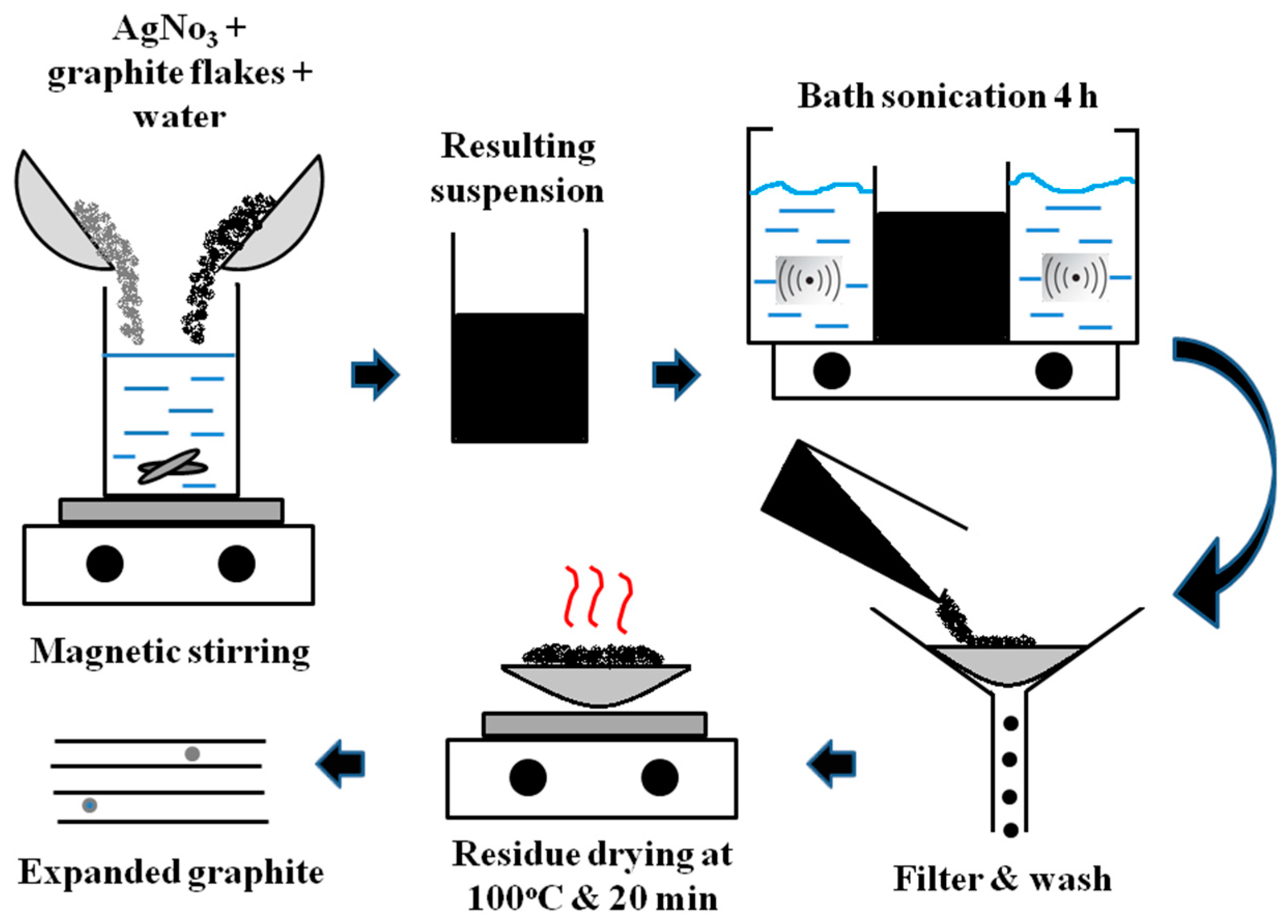
2.2. Synthesis of Graphite Particles Using Process of Bath Sonication (First Route)

In this process, silver nitrate and commercial graphite flakes in a 1:1 ratio by weight were thoroughly stirred in deionized water using a magnetic stirrer until a black colored suspension was formed. The glass bottle containing the suspension was then placed in a bath sonicator containing distilled water and sonication was continuously applied for 4 h at a frequency of greater than 20 kHz. After sonication, the suspension was filtered and washed using deionized water. Finally, the residue collected over the filter paper was dried on a hot plate at 100 °C for 20 min to render the so-called expanded graphite particles. Figure 1 depicts the schematic of this process.

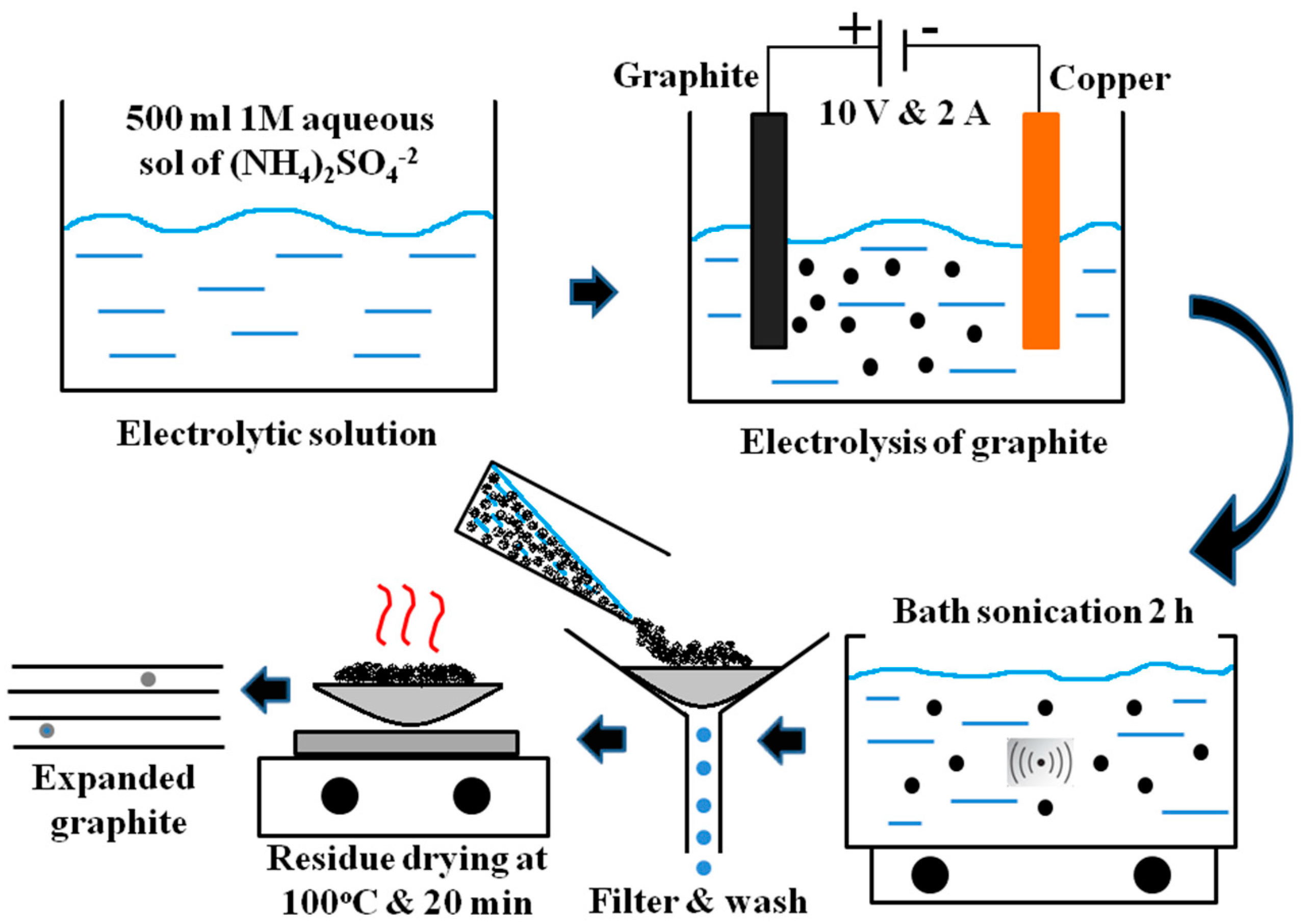
2.3. Synthesis of Graphite Particles Using Process of Electrolysis (Second Route)

In this process a two-electrode electrochemical cell was used for the synthesis of expanded graphite particles. The graphite plate was made the anode while the copper plate was used as a cathode. The electrolyte was 500 mL 1 M solution of ammonium sulfate salt ((NH4)2SO4) in distilled water. The process was carried out for 2 h at a voltage of 10 V with a constant current of 2 A. During this process, the graphite particles exfoliated away from the anode and kept on dispersing within the electrolyte. The electrolyte containing the suspended graphite particles was bath sonicated for 2 h followed by filtering and washing using deionized water. Finally, the residue was collected and dried on a hot plate at 100 °C and 20 min to render the expanded graphite particles. Figure 2 shows the schematic diagram of this process.

2.4. Synthesis of Ink, PDMS Substrate and Expanded Graphite Thin Films

The ink containing the collected graphite particles for both the cases discussed above was prepared by thoroughly mixing 1.5 gm of the collected particles in 10 mL of DMF. DMF acts as a solvent for the ink and also as a conductive binder between expanded graphite particles within the thin films. In this work, the as-synthesized ink was thoroughly shaken each time before the fabrication of graphite films. In order to prepare PDMS substrates, the base and the cross linker were mixed together thoroughly in a ratio of 20:1 by weight. The solution was centrifuged at high rpm until all the air bubbles were removed. Molds were prepared using glass slabs that were 5 cm squared in size. Scotch tape was attached on one surface of the glass slabs for easy removal of the PDMS and the sides were secured using pieces of cardboard and scotch tape. Then, 2.5 mL of clear PDMS solution was poured at the center of the molds and left to cure at room temperature for 2 to 3 days, after which the PDMS substrates were cut in dimensions of 1 cm (width) × 4 cm (length) × 2 mm (thick). The as-fabricated PDMS substrates were found to remain reasonably stretchable and flexible for testing the films. In this work thin films of graphite on stretchable and flexible PDMS substrates were simply prepared by using a paint brush technique until the substrates were uniformly coated with the ink. The films were left to cure at room conditions for 24 h before performing the mechanical tests. By studying various lateral scanning electron micrographs (SEM) of the as-fabricated laminate, the average thickness of the graphite films in this work was found to remain 15 ± 1.37 μm. Figure 3 depicts a typical image of the film thickness.

2.5. Characterizations

From a material characterization point of view X-ray diffraction was performed for the collected expanded graphite particles in order to ensure the graphite phase and possible traces of other materials, such as silver and sulfate ions. The film resistances were measured using a digital multimeter with an accuracy of ± 1%. Three types of mechanical characterizations were performed on the as-fabricated films. Firstly, the mechanical stretchability was characterized using a homemade thin film tensile tester. In this test the graphite/PDMS laminate was secured between the fixed and moveable clamps of the apparatus and it was stretched slowly by giving deformation in steps of 0.5 mm. After each step the resistance of the film was recorded. The stretchability testing was continued until the multimeter registered an open circuit. The second characterization was performed to quantify the mechanical flexibility of the as-fabricated films. In this test, the graphite/PDMS laminates were conformally wrapped around circular objects of varying diameters and the film resistance was recorded. It is to be noted that the tensile test induces tensile strain in the films, whereas the flexibility test induces bending strain in the films. The third mechanical characterization used in this study was rather to check the reliability of the as-prepared films. In this test a typical graphite/PDMS laminate was secured between the thumb and the index finger of the experimentalist and was pressed and then quickly depressed multiple times until the film was found to fail. The film resistance was recorded intermittently during the reliability tests. Figure 4 depicts all types of mechanical characterizations used in this work.

3. Results and Discussion

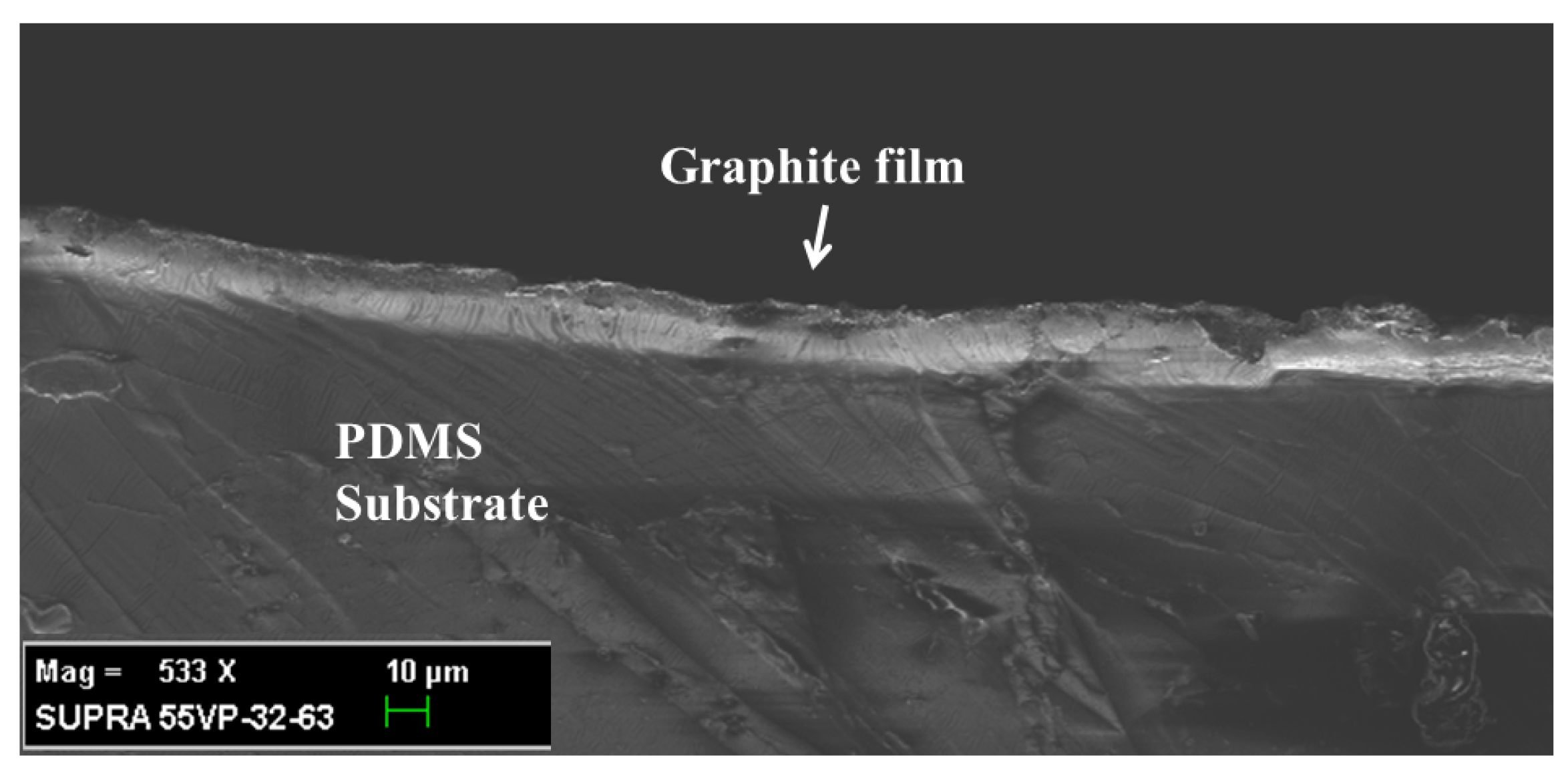
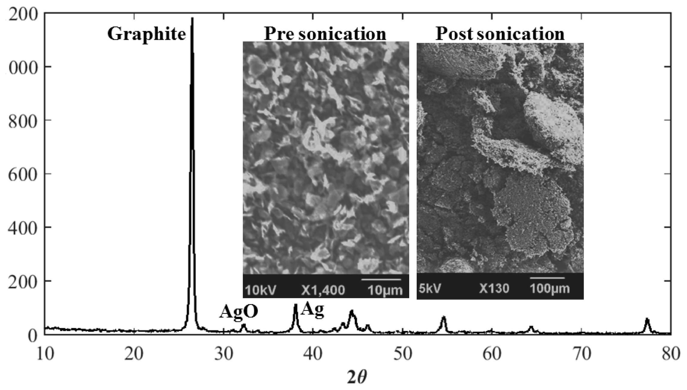
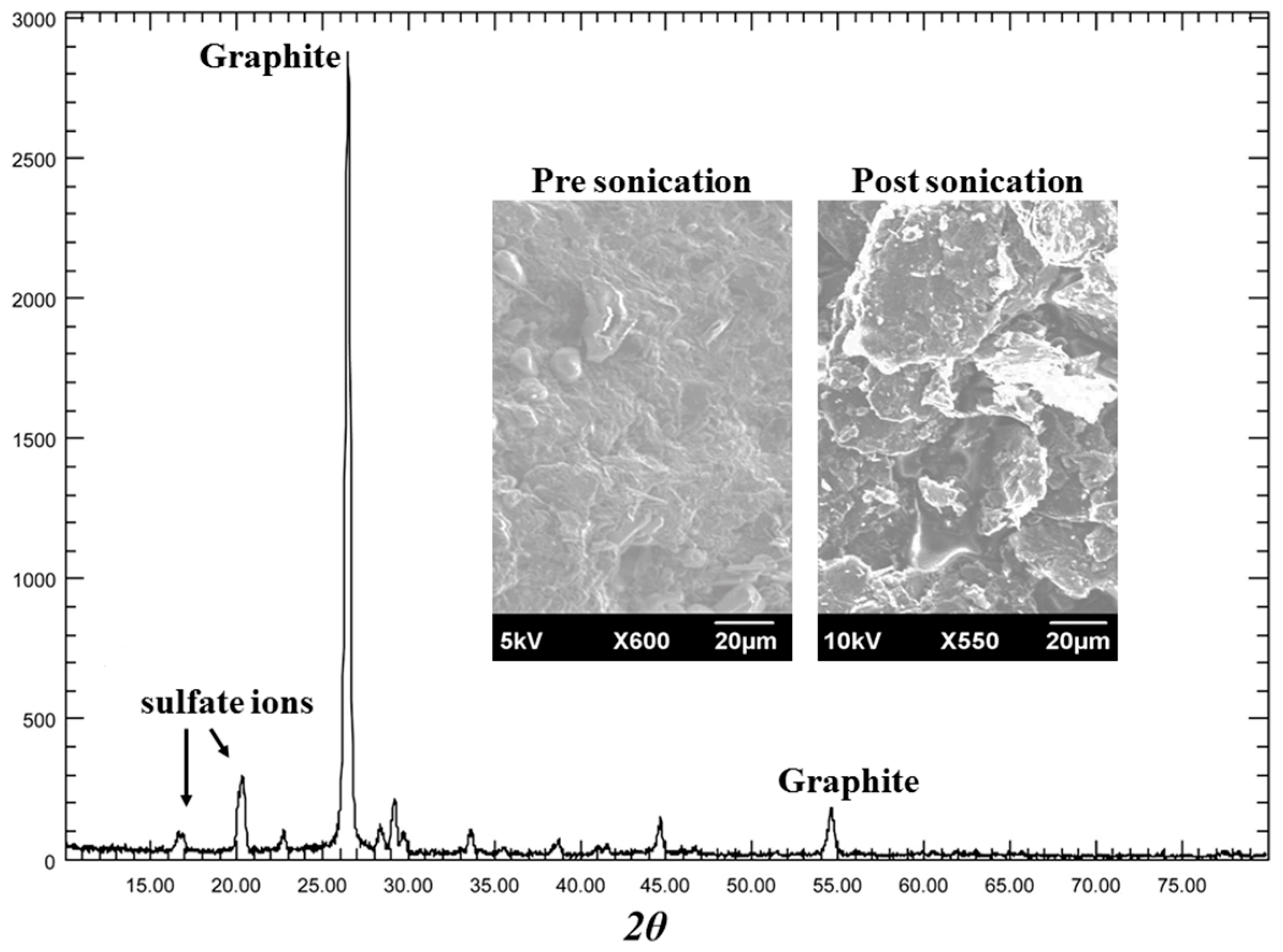
3.1. Material and Morphology of Expanded Graphite Particles

Figure 5 represents the XRD pattern of the expanded graphite flakes obtained by following the bath sonication process of commercial graphite flakes—i.e., the first route. In Figure 5 it can be seen that, as compared to the pure graphite, which is known to exhibit a characteristic peak at 26.53°, the XRD pattern of the expanded graphite flakes have also shown peaks at 32° and 38°. After comparing with various peaks of silver and its compounds, it was concluded that these new peaks refer to silver oxide and silver, respectively. This confirms the presence of silver and its compound in the expanded graphite flakes during the bath sonication process. SEM images shown in Figure 5 as insets also confirm the fact that, after performing the bath sonication process, the graphite flakes have become swollen and increased in overall size, which indicates that the graphite layers have, indeed, expanded during the process. This mechanism was ultimately found to reduce the film resistances by three orders of magnitude, as compared to the films of pristine graphite particles.
On the other hand, Figure 6 shows the XRD pattern of expanded graphite particles collected through the process of electrolysis—i.e., the second route. Compared to the XRD pattern of pure graphite, several other characteristic peaks can be observed. These new peaks are due to the presence of sulfate ions. The peaks appear at angles of 16.87°, 20.43° and 22.78° with higher inter-atomic spacing of 5.25 Å, 4.34 Å and 3.90 Å, respectively. Higher inter-atomic spacing in the sample suggests that intercalation by the combined action of bath sonication and sulfate ions during electrolysis have been achieved. Again, it can be seen from the SEM images given in Figure 6 as insets that, after performing the bath sonication, the particle size has indeed increased, which qualitatively indicates the intercalation effect. The film resistances were lowered by three orders of magnitude, as compared to the films of pristine graphite particles. However, in this case it was noted that the film resistances on average remained five times lower than the film resistances prepared by the first route. This decrease in the film resistance is attributed to higher d-spacing caused by the sulfate ion as compared to the d-spacing caused by the intercalation of silver, which remains at 2.77 Å and 2.37 Å at angles of 32° and 38°, respectively.

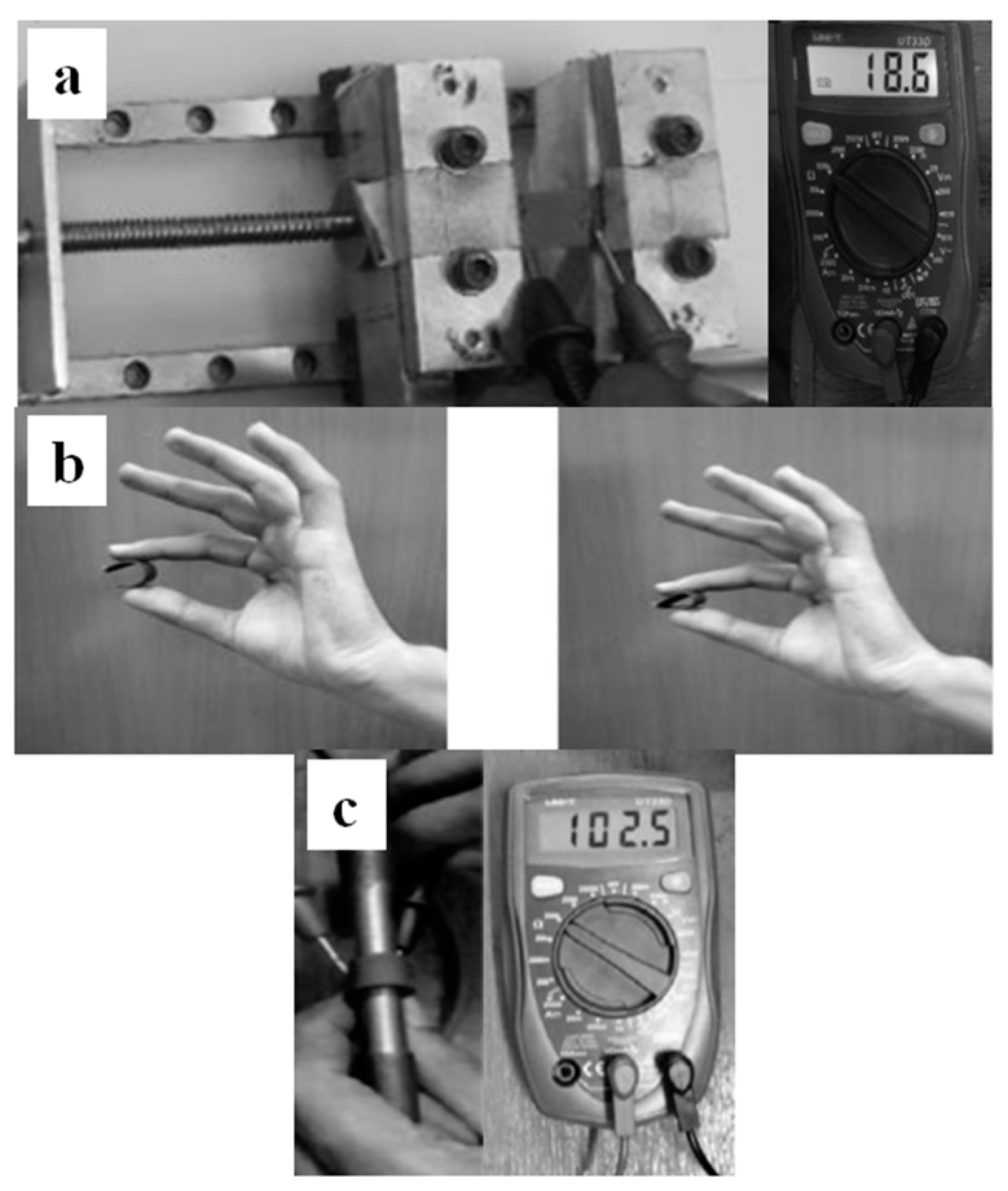
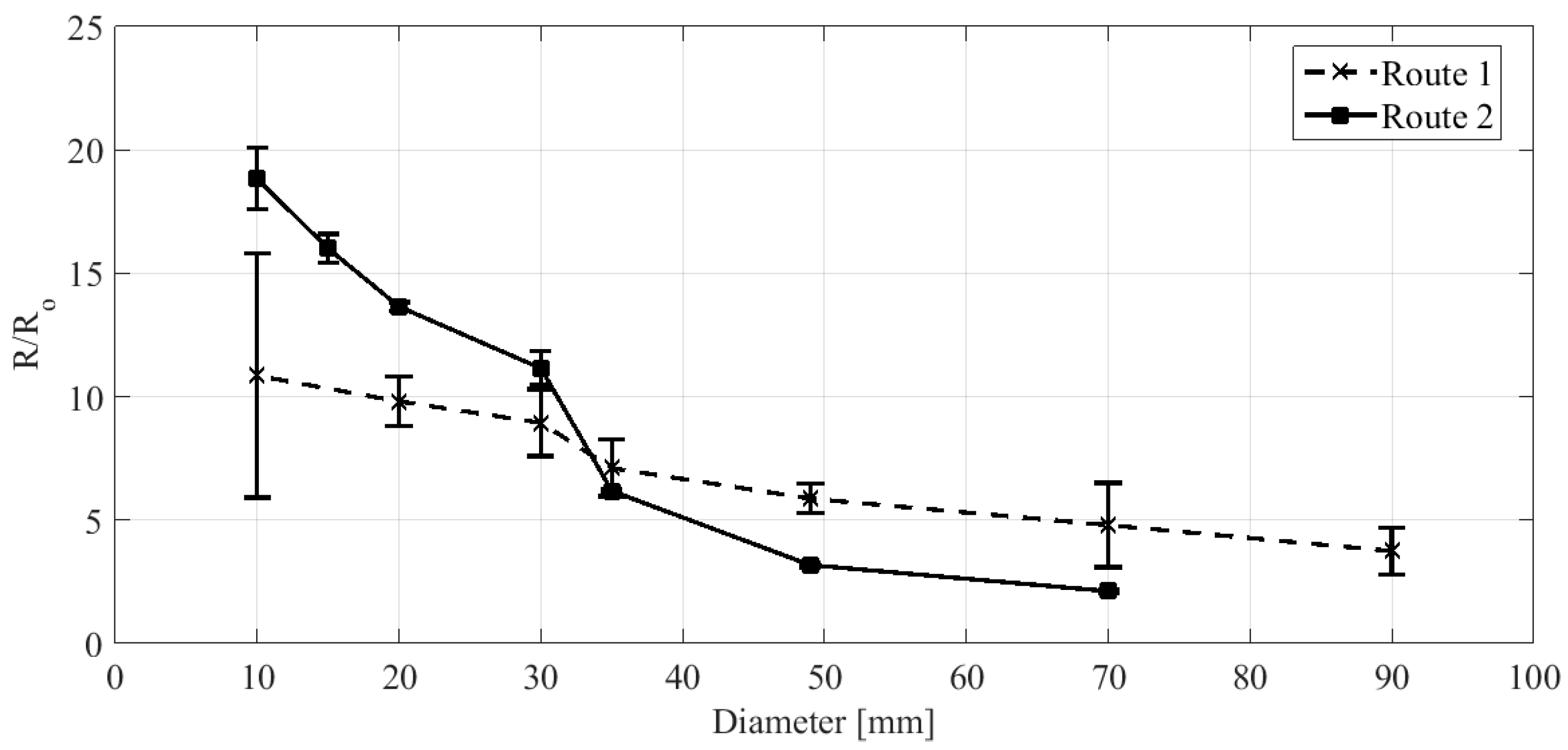
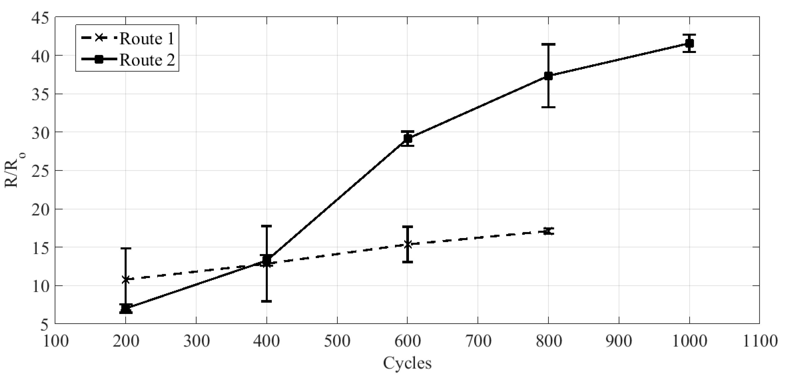
3.2. Stretchability, Flexibility and Reliability of Expanded Graphite Thin Films

Figure 7 depicts the change in normalized resistance of the films prepared by following the first route and the second route against the applied tensile strains. It can be seen that expanded graphite films prepared by following the second route are approximately 1.3 times more stretchable than the first route. This is due to the fact that expanded graphite particles synthesized by following the second route were exfoliated from a hard graphite plate as an anode. Owing to this reason, the films formed by these expanded graphite particles were slightly higher in strength and therefore could bare larger tensile strains before failure. On the other hand, it could be observed that, up to 25% tensile strains, both films showed almost linear behavior and the increase in resistance of the films remains less than 10 in both cases. Specially, the films prepared by the first route showed even less increases in resistance. Thin film piezoresistive coefficient can be considered as a parameter that highlights the dependency of the resistance on resistivity changes due to mechanical loads. In order to estimate the gage factor and thus the piezoresistive coefficient for the as-fabricated films the experimental data shown in Figure 7 could be used in combination with the equation of the form [ Δ R R o = R R o 1 = ( 1 + ϑ + β ) ε = G F .   ε   ] [24], where ϑ is the Poisson ratio of graphite films taken to be 0.2 [25], R is the final film resistance, Ro is the initial film resistance, β is the piezoresistive coefficient of the film material, GF is the gage factor and ε is the applied tensile strain. Using the values from Figure 7 it can be estimated that the gage factors GF for the as-fabricated films comes out to be 9.9 and 37.33 for the first route and the second route, respectively. Therefore, the piezoresistive coefficients are 8.7 and 36.13 for the first route and second route, respectively. This suggests that the change in resistivity of the material during mechanical loading affects the films prepared by the second route more strongly, which is the reason for higher resistance change during stretching for these films. These results fairly suggest the applicability of expanded graphite thin films in stretchable electronic devices.
Figure 8 shows the variation in normalized resistance against the bending diameters. This graph can be considered as the quantitative measure of the flexibility of as-fabricated expanded graphite thin films. It is to be noted that, in this scenario, unlike the case of stretchability, the as-fabricated films are subjected to increasing bending strains. From Figure 8 it can be noticed that both the films remain functional until they are conformally wrapped around a circular rod of 10 mm diameter, which translates to a maximum bending strain of 20% using the equation of the form [ ε = t f + t s D ] where tf is the average film thickness, ts is the thickness of the substrate and D is the bending diameter [26]. High gage factors of 49.3 and 89.2 for the films prepared by the first route and the second route, respectively, are estimated. This suggests that the as-fabricated films are capable of bending and can be flexibly operated up to a maximum of 20% bending strains with high strain sensitivity.
In order to conclude, the mechanical characterizations reliability tests were performed on the as-fabricated films and the results were shared in Figure 9. This figure shows the change in normalized resistance of the as-fabricated films against the number of flexure cycles. Both the films were found to withstand repeated flexure cycles, with films prepared by the second route slightly over performing the films prepared by the first route. However, the film resistance changed by 41.57 and reached a value of 46.97 kΩ.

4. Conclusions

To conclude, this paper presented the mechanical stretchability, flexibility and reliability of expanded graphite thin films on polymer substrate PDMS. The expanded graphite particles were prepared using the bath sonication of commercial graphite flakes (the first route) and graphite particles obtained through electrolysis (the second route) under interstitial substitution. It was concluded that, due to bath sonication and favorable effects of electrolysis and sulfate ions, the intercalation was much more effective, resulting in lower initial film resistances. Additionally, from the perspective of mechanical characterizations, the films prepared by following the second route seem to over perform the films prepared by the first route. However, due to the strong dependency on the piezoresistive part, a higher change in resistance was observed during the mechanical loading of the films prepared by the second route. Nevertheless, both types of film were found to remain stretchable, flexible, and functional, even at repeated flexures. Various results in this paper have shown that the as-fabricated expanded graphite thin films demonstrate favorable mechanical performance, which can be used in various stretchable and flexible electronics applications.

Author Contributions

M.M.N. did the conceptualization, methodology and funding acquisition; M.M. designed the experiments and wrote the manuscript; H.A. (Hasan Askari), B.A.B., A.U.R., H.A. (Hassan Abbas), Z.H. and D.Z. performed the experiments; D.H., J.H.Z. and M.S.A.B. did the analyses and edited the manuscript. All authors have read and agreed to the published version of the manuscript.

Funding

This research was funded by the Universiti Brunei Darussalam’s University Research Grant Number UBD/RSCH/URC/RG(b)/2019/008.

Acknowledgments

The authors would like to thank NED University of Engineering and Technology Pakistan for its support.

Conflicts of Interest

The authors declare no conflict of interests.

References

  1. Wu, Y.; Pan, Q.; Zheng, F.; Ou, X.; Yang, C.; Xiong, X.; Liu, M.; Hu, D.; Huang, C. Sb@C/expanded graphite as high-performance anode material for lithium ion batteries. J. Alloy Compd. 2018, 744, 481–486. [Google Scholar] [CrossRef]
  2. Kim, J.; Yoon, G.; Kim, J.; Yoon, H.; Baek, J.; Lee, J.H.; Kang, K.; Jeon, S. Extremely large, non-oxidized graphene flakes based on spontaneous solvent insertion into graphite intercalation compound. Carbon 2018, 139, 309–316. [Google Scholar] [CrossRef]
  3. Lee, S.W.; Lee, W.; Hong, Y.; Lee, G.; Yoon, D.S. Recent advances in carbon material-based NO2 gas sensors. Sens. Actuators B Chem. 2018, 255, 1788–1804. [Google Scholar] [CrossRef]
  4. Ali, K.; Choi, K.-H.; Muhammad, N.M. Roll-to-roll atmospheric atomic layer deposition of Al2O3 thin films on PET substrates. Chem. Vap. Dep. 2014, 20, 380–387. [Google Scholar] [CrossRef]
  5. Li, C.; Xie, B.; Chen, D.; Chen, J.; Li, W.; Chen, Z.; Gibb, S.W.; Long, Y. Ultrathin graphite sheets stabilized stearic acid as a composite phase change material for thermal energy storage. Energy 2019, 166, 246–255. [Google Scholar] [CrossRef]
  6. Dao, V.-D.; Choi, H.-S. Carbon-Based Sunlight Absorbers in Solar-Driven Steam Generation Devices. Glob. Chall. 2008, 2, 1700094. [Google Scholar] [CrossRef]
  7. Natarajan, S.; Lakshmi, D.S.; Bajaj, H.C.; Srivastava, D.N. Recovery and utilization of graphite and polymer materials from spent lithium-ion batteries for synthesizing polymer-graphite nanocomposite thin films. J. Environ. Chem. Eng. 2015, 3, 2538–2545. [Google Scholar] [CrossRef]
  8. Afify, A.S.; Ahmad, S.; Khushnood, R.A.; Jagdale, P.; Tulliani, J.-M. Elaboration and Characterization of novel humidity sensor based on micro-carbonized bamboo particles. Sens. Actuators B Chem. 2017, 239, 1251–1256. [Google Scholar] [CrossRef]
  9. Jeong, J.; Kim, S.; Cho, J.; Hong, Y. Stable Stretchable Silver Electrode Directly Deposited on Wavy Elastomeric Substrate. IEEE Electron Device Lett. 2009, 30, 1284–1286. [Google Scholar] [CrossRef]
  10. Kim, D.-H.; Lu, N.; Ma, R.; Kim, Y.-S.; Kim, R.-H.; Wang, S.; Wu, J.; Won, S.M.; Tao, H.; Islam, A.; et al. Epidermal electronics. Science 2011, 333, 838–843. [Google Scholar] [CrossRef] [Green Version]
  11. Lipomi, D.J.; Tee, B.C.-K.; Vosgueritchian, M.; Bao, Z. Stretchable organic solar cells. Adv. Mater. 2011, 23, 1771–1775. [Google Scholar] [CrossRef] [PubMed]
  12. White, M.S.; Kaltenbrunner, M.; Głowacki, E.D.; Gutnichenko, K.; Kettlgruber, G.; Graz, I.; Aazou, S.; Ulbricht, C.; Egbe, D.A.M.; Miron, M.C.Z.; et al. Ultrathin, highly flexible and stretchable PLEDs. Nat. Photonics 2013, 7, 811–816. [Google Scholar] [CrossRef]
  13. Brown, E.W. Octacalcium phosphate and hydroxyapatite. Nature 1962, 196, 1048–1050. [Google Scholar] [CrossRef]
  14. Cho, C.-K.; Hwang, W.-J.; Eun, K.; Choa, S.-H.; Na, S.-I.; Kim, H.-K. Mechanical flexibility of transparent PEDOT:PSS electrodes prepared by gravure printing for flexible organic solar cells. Sol. Energy Mater. Sol. Cells 2011, 95, 3269–3275. [Google Scholar] [CrossRef]
  15. Lee, J.-H.; Lee, K.Y.; Gupta, M.K.; Kim, T.Y.; Lee, D.-Y.; Oh, J.; Ryu, C.; Yoo, W.J.; Kang, C.-Y.; Yoon, S.-J.; et al. Highly stretchable piezoelectric-pyroelectric hybrid nanogenerator. Adv. Mater. 2007, 26, 765–769. [Google Scholar] [CrossRef]
  16. Geim, A.K.; Novoselov, K.S. The rise of graphene. Nat. Mater. 2007, 6, 183–191. [Google Scholar] [CrossRef]
  17. Nuvoli, D.; Valentini, L.; Alzari, V.; Scognamillo, S.; Bon, S.B.; Piccinini, M.; Illescas, J.; Mariani, A. High concentration few-layer graphene sheets obtained by liquid phase exfoliation of graphite in ionic liquid. J. Mater. Chem. 2011, 21, 3428–3431. [Google Scholar] [CrossRef]
  18. Niu, L.; Li, M.; Tao, X.; Xie, Z.; Zhou, X.; Raju, A.P.A.; Young, R.J.; Zheng, Z. Salt-assisted direct exfoliation of graphite into high-quality, large-size, few-layer graphene sheets. Nanoscale 2013, 5, 7202–7208. [Google Scholar] [CrossRef]
  19. Jin, J.; Leesirisan, S.; Song, M. Electrical conductivity of ion-doped graphite/polyethersulphone composites. Compos. Sci. Technol. 2010, 70, 1544–1549. [Google Scholar] [CrossRef] [Green Version]
  20. Parvez, K.; Wu, Z.S.; Li, R.; Liu, X.; Graf, R.; Feng, X.; Müllen, K. Exfoliation of graphite into graphene in aqueous solutions of inorganic salts. J. Am. Chem. Soc. 2014, 136, 6083–6091. [Google Scholar] [CrossRef] [Green Version]
  21. Kato, R.; Hasegawa, M. Fast synthesis of thin graphite film with high-performance thermal and electrical properties grown by plasma CVD using polycrystalline nickel foil at low temperature. Carbon 2019, 141, 768–773. [Google Scholar] [CrossRef]
  22. Yudasaka, M.; Kikuchi, R.; Matsui, T.; Kamo, H.; Ohki, Y.; Yoshimura, S.; Ota, E. Graphite thin film formation by chemical vapor deposition. Appl. Phys. Lett. 1994, 64, 842–844. [Google Scholar] [CrossRef]
  23. Luo, S.; Liu, T. SWCNT/graphite nanoplatelet hybrid thin films for self-temperature- compensated, highly sensitive, and extensible piezoresistive sensors. Adv. Mater. 2013, 25, 5650–5657. [Google Scholar] [CrossRef] [PubMed]
  24. Lang, U.; Rust, P.; Schoberle, B.; Dual, J. Piezoresistive properties of PEDOT:PSS. Microelectron. Eng. 2009, 86, 330–334. [Google Scholar] [CrossRef]
  25. Politano, A.; Chiarello, G. Probing the Young’s modulus and Poisson’s ratio in graphene/metal interfaces and graphite: A comparative study. Nano Res. 2015, 8, 1847–1856. [Google Scholar] [CrossRef]
  26. Suo, Z.; Ma, E.Y.; Gleskova, H.; Wagner, S. Mechanics of rollable and foldable film-on-foil electronics. Appl. Phys. Lett. 1999, 74, 1177–1179. [Google Scholar] [CrossRef]
Figure 1. Schematic of first route. Arrows indicate the step by step procedure for obtaining expanded graphite particles using bath sonication.
Processes 08 00961 g001
Figure 2. Schematic of second route. Arrows indicate the step by step procedure for obtaining expanded graphite particles using electrolysis of graphite.
Processes 08 00961 g002
Figure 3. Lateral scanning electron microscope (SEM) image of a typical graphite thin film. The lateral cross-sectional image was viewed at an angle of 90 degrees.
Processes 08 00961 g003
Figure 4. Various mechanical tests performed on the as-fabricated graphite/PDMS laminate. (a) Tensile test, (b) repeated reliability testing, and (c) bending test.
Processes 08 00961 g004
Figure 5. X-ray diffraction pattern of expanded graphite particles prepared by first route. The insets show the scanning electron micrograph (SEM) images of the expanded graphite particles before and after bath sonication.
Processes 08 00961 g005
Figure 6. X-ray diffraction pattern of expanded graphite particles prepared by second route. The insets show the scanning electron micrograph (SEM) images of the expanded graphite particles before and after bath sonication.
Processes 08 00961 g006
Figure 7. Stretchability curves of expanded graphite thin films. Error bars show standard deviations between the tested samples.
Processes 08 00961 g007
Figure 8. Bending curves indicating the flexibility of expanded graphite thin films. Error bars show standard deviations between the tested samples.
Processes 08 00961 g008
Figure 9. Reliability curves of expanded graphite thin films. Error bars show standard deviations between the tested samples.
Processes 08 00961 g009

