Quick Response Circulating Water Cooling of ±3 mK Using Dynamic Thermal Filtering


Center of Ultra-precision Optoelectronic Instrument, Harbin Institute of Technology, Harbin 150080, China
*
Author to whom correspondence should be addressed.
Appl. Sci. 2020, 10(16), 5483; https://doi.org/10.3390/app10165483
Submission received: 17 June 2020
/
Revised: 5 August 2020
/
Accepted: 6 August 2020
/
Published: 7 August 2020
(This article belongs to the Special Issue Manufacturing Metrology)
Abstract
:Featured Application
The circulating cooling water machine proposed in this paper is conductive to the thermal management of equipment and facilities in the field of precision manufacturing and measurement. It has already been applied to our lithography development project.
Abstract
An enhanced circulating cooling water (CCW) machine is developed to simultaneously achieve high temperature stability and dynamic performance of CCW temperature control. Dynamic thermal filtering based on an auto-updatable thermal capacity medium is proposed to reduce the temperature fluctuation of the CCW. Agile thermal control is presented to realize a quick response and high resolution of temperature control, through thermal inertia minimization and bidirectional regulation of heating/cooling power. Experimental results indicate that a temperature stability of ±3 mK (peak to peak value) and a settling time of 128 s, corresponding to a 1 K step set value, are achieved. It can therefore be concluded that the developed machine can satisfy the challenging requirements of precision manufacturing.
1. Introduction
Thermal management using circulating cooling water (CCW) is essential for precision manufacturing [1]. With precision manufacturing stepping into a nano-era, the challenging demand for CCW with mK level stability and a quick response is put forward by a variety of ultraprecision applications, such as ultraprecision optical machining with nanometer accuracy, and lithography which is stepping to a 7 nm technical node [2,3]. In an advanced lithography machine, CCW with a temperature stability of ± 0.01 K is required to cool down power devices like motors, power drivers, laser sources, and so on [4,5], especially to maintain a ±0.01 K temperature stability of objective lenses. Moreover, CCW is also used as a temperature reference medium to produce an ‘air shower’ of temperature stability, up to 2.3 mK/5 min, for air refractive index stabilization of laser interferometry. Meanwhile, a response time of CCW temperature control as short as dozens of seconds is demanded to suppress the cyclic thermal pollution of power devices in lithography. Similar requirements are also presented in ultraprecision optical machining. CCW with a temperature stability of ±0.1 K is needed to cool down electrical spindles [6,7], and the temperature of CCW needs to dynamically respond to the variation in rotation speed of spindles, and thus to realize ‘servo’ thermal pollution management of the spindles.
One effective technical route to achieve high temperature stability of CCW is to reduce the temperature fluctuation by increasing thermal inertia. Lawton et al., proposed a method to reach this goal through heat exchanging with an additionally introduced thermal capacity medium, such as water, and stainless steel balls [8,9]. Phase change material (PCM) has also been utilized, because of its large latent thermal capacity at the phase change temperature point [10,11,12]. However, the proposed methods only function in the very narrow range of the preset temperature point of the introduced thermal capacity medium, or the phase change temperature point of PCM. Therefore, they can only reduce the CCW temperature fluctuation in static water-cooling applications in which the output temperature of CCW is required to be constant.
New control schemes and algorithms have also been presented to improve the temperature stability and dynamic performance of CCW. For example, Madhavan et al., and Sarid et al., proposed temperature controllers achieving temperature stability at sub-millikelvin level [13,14,15]. However, the response time of CCW temperature control in these studies ranged from tens of minutes to hours, because the dynamic performance was not taken into consideration. Liu et al., proposed a ‘servo’ temperature control method for the cooling of spindles of precision machining tools [16]. Two CCW streams from two CCW machines with different temperature set values were used, then temperature of the mixed CCW was proportional to the mixing proportion of the two streams. Temperature stability at sub-kelvin level and a quick response of CCW temperature control were realized, at the cost of using two CCW machines and a complex flow rate control.
Therefore, it is difficult to simultaneously achieve high temperature stability and quick response of CCW temperature control. CCW with temperature stability at mK level and a response time at ~100 s level is still a challenging demand for precision manufacturing. Thus, this paper proposes an enhanced CCW machine using a dynamic thermal filtering method (DTFM) and bidirectional agile thermal control to solve this problem.
2. Principle
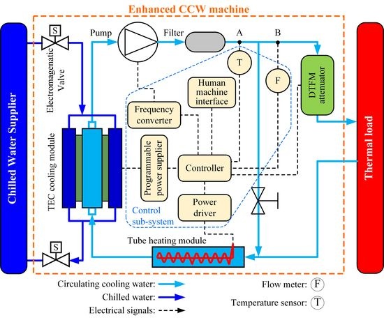
As shown in Figure 1, the proposed enhanced CCW machine mainly consists of a water circulating loop and a control sub-system. A frequency variable pump, a heating module, a cooling module, a DTFM attenuator, and a thermal load are cascaded as a water circulating loop. The pump drives the cooling water to circulate through the loop, and the temperature of CCW is regulated by the cooling and heating modules. Then, the DTFM attenuator is introduced to further improve the temperature stability of CCW. The chilled water supplier, which is normally a factory facility, serves as a cooling source to carry away dissipated thermal energy from the cooling module.
The control sub-system takes charge of the temperature feedback control, the flow rate feedback control, and the human-machine interface. The dynamic performance of CCW temperature control is improved by distributive thermal inertia minimization, and bidirectional agile control of the heating and cooling power.
3. Dynamic Thermal Filtering to Achieve High Temperature Stability
3.1. Principle
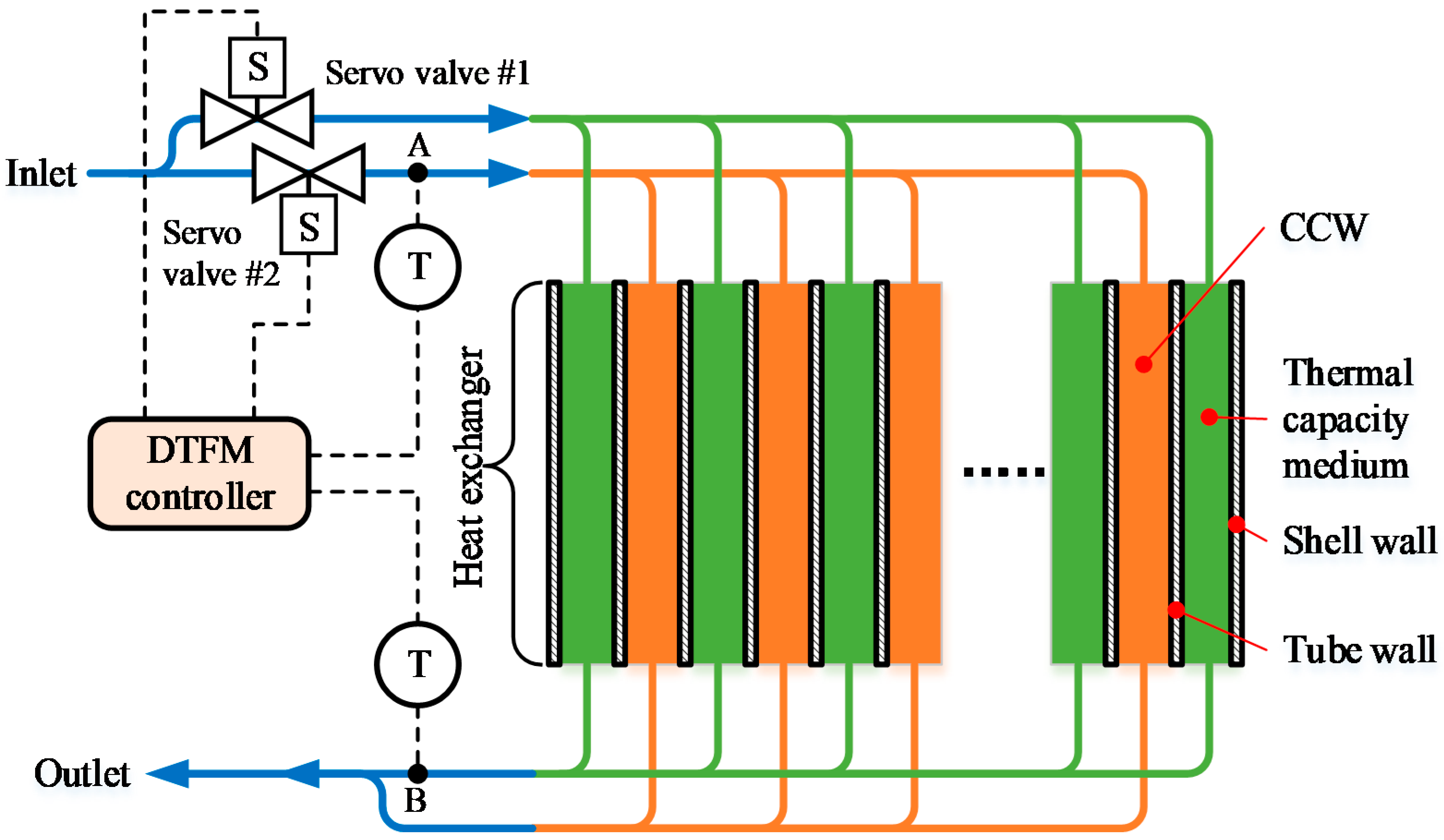
The scheme of the proposed DTFM is shown in Figure 2. The idea is to attenuate the CCW temperature fluctuation through heat exchanging with the thermal capacity medium. The temperature of the thermal capacity medium dynamically follows the set value of the CCW temperature, since the medium can automatically update. Thus, the temperature stability of CCW is further improved without any deterioration of the dynamic performance of CCW temperature control.
As shown in Figure 2, the DTFM attenuator mainly consists of a heat exchanger, two temperature sensors, two servo valves, and a controller. When the DTFM attenuator is working, some water is bypassed from CCW and blocked in one chamber of the heat exchanger, serving as a thermal capacity medium. Heat exchange between CCW and the thermal capacity medium, called ‘thermal filtering effect’, occurs when CCW flows through the other chamber of the heat exchanger. As a result, the temperature fluctuation of the CCW is significantly reduced, which means that the temperature stability of the CCW is effectively improved.
When the machine is applied in dynamic water-cooling applications in which the temperature of CCW varies with time, temperature sensor A detects the change of CCW temperature, then the attenuator starts the process of automatically updating the thermal capacity medium. The controller switches on servo valve #1 and switches off servo valve #2 to make the latest CCW flow into the thermal capacity medium chamber. Temperature sensor B monitors the temperature of outflow of the thermal capacity medium, and provides a trigger signal to the controller when the temperature at point B equals the temperature at point A. Then, the controller switches off servo valve #1 and switches on servo valve #2 to end the process of medium updating. Consequently, the change of the set value of the CCW temperature is dynamically followed and the dynamic performance of the CCW machine is maintained
3.2. Structure of DTFM Attenuator
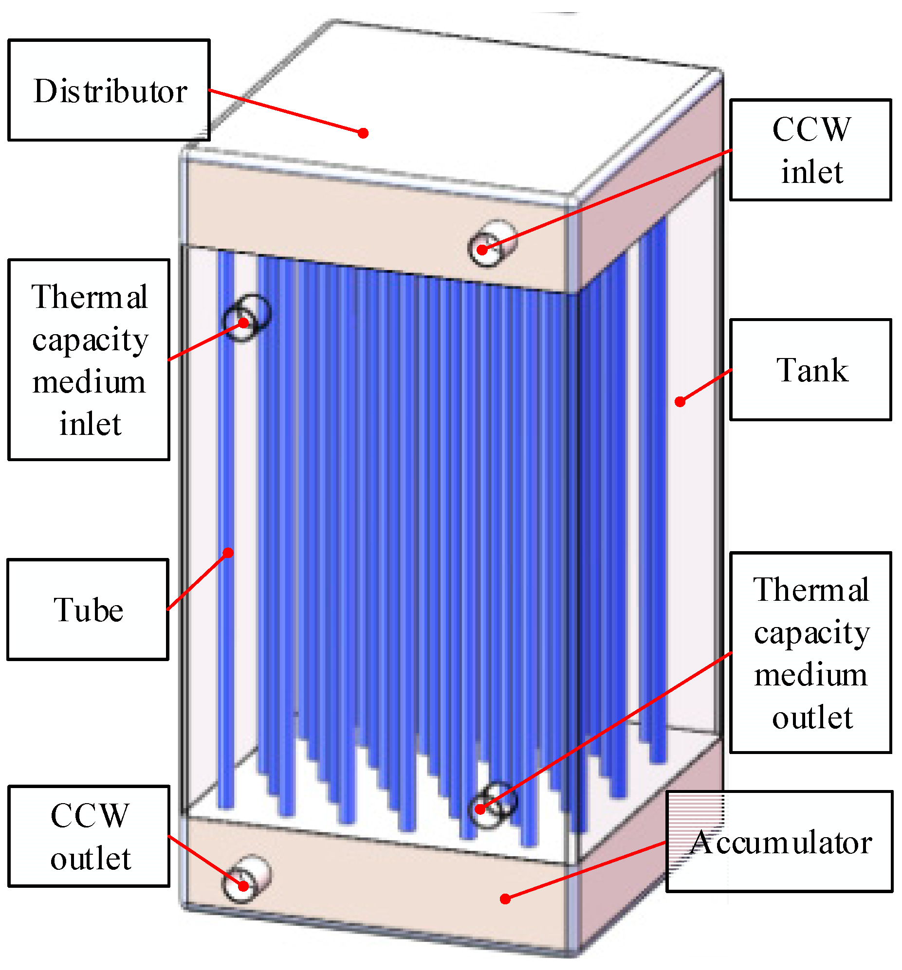
A DTFM attenuator was designed using a custom-made tube-tank heat exchanger, as shown in Figure 3. A tube array is evenly arranged in a square stainless steel tank. CCW flows through the tubes, and the thermal capacity medium is blocked in the tank. A distributor is placed on the top of the exchanger and divides CCW into sub-streams flowing into tubes. An accumulator is placed at the bottom of the exchanger and makes all the sub-streams converge.
3.3. Modeling
The temperature fluctuation attenuation ratio of the DTFM attenuator was modeled using a transfer function method, based on the equations proposed by Lawton et al. [8]. Transfer functions of the distributor, tube-tank, and accumulator, expressed as rdis, ratt, and racc, respectively, were defined as the temperature fluctuation ratios of the output CCW temperature to input CCW temperature of each part. In the distributor, convective heat transfer of CCW plays the key role in the temperature fluctuation attenuation. The temperature fluctuation attenuation of the tube-tank can be modeled through the double-pipe heat exchanger. The temperature fluctuation attenuation of accumulator resulted from CCW sub-streams mixing. Therefore, the transfer functions of the three parts of the DTFM attenuator can be derived as the following equations:
where ρ is the density of water, Vacc is the volume of the accumulator, Fm is the mass flow rate of the CCW, fm is the mass flow rate of each tube, ua is the average water velocity in the accumulator, λ is the thermal conductivity of water, Ca is the thermal capacity of a single tube, La and Ld are height of the accumulator and distributor respectively, cw is the specific thermal capacity of water, and R is the thermal resistance of the attenuator.
Then, the total temperature fluctuation attenuation ratio of the DTFM attenuator r is the product of transfer functions of the three parts.
The main parameters of the designed DTFM attenuator are listed in Table 1.
Before the DTFM attenuator is introduced into the CCW machine, the dynamic performance of the CCW temperature control is determined by the closed loop feedback temperature control of the CCW machine. After the DTFM attenuator is introduced, the response time of the CCW temperature control Ssys can be expressed as:
where Smac is the response time of temperature control before the DTFM attenuator is introduced and Smed is the updating time of the thermal capacity medium of the DTFM attenuator, expressed as:
Therefore, Smac > Smed should be satisfied to guarantee the dynamic performance of the CCW temperature control.
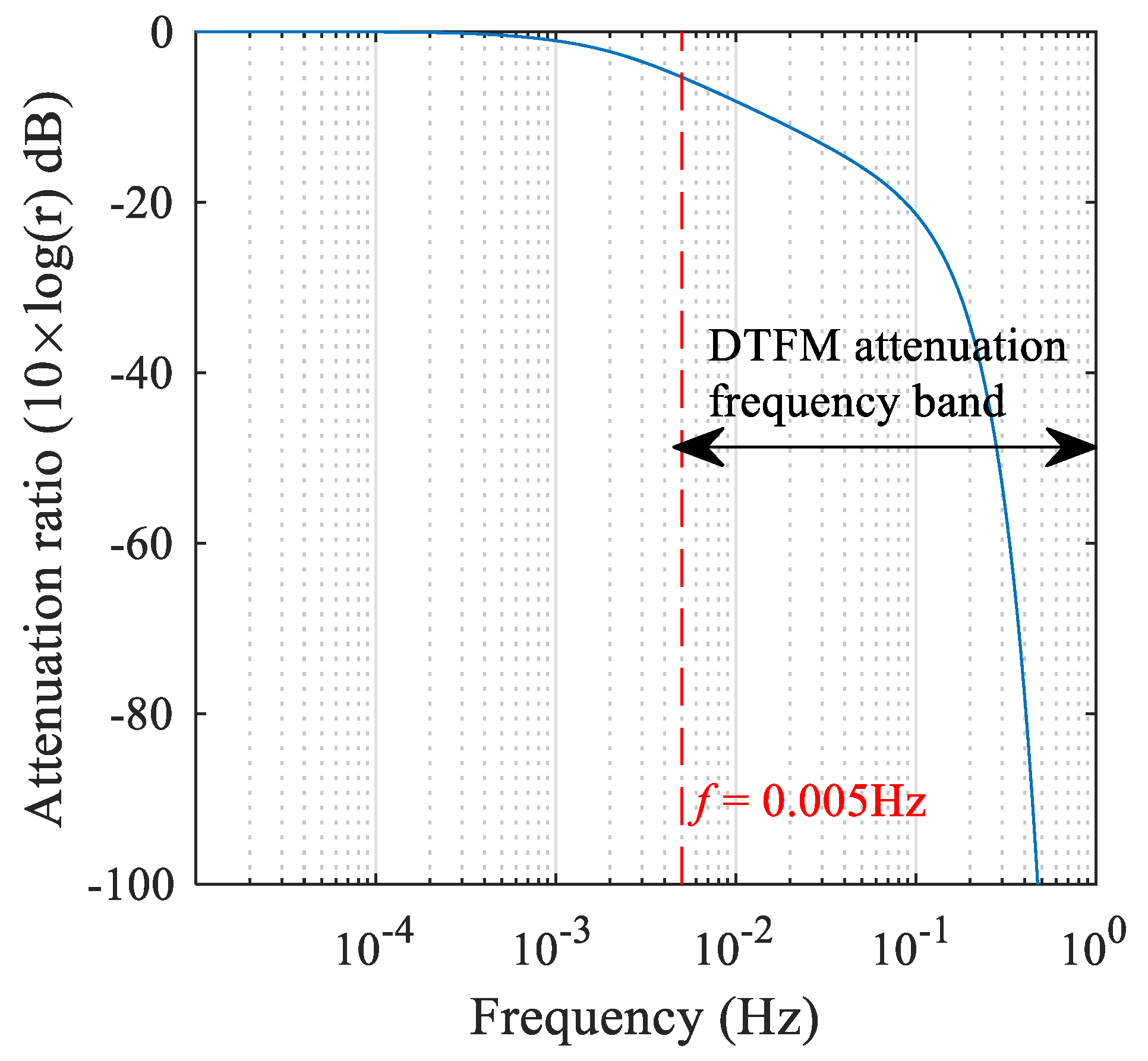
In this research, the frequency band of the closed loop temperature feedback control of the CCW machine was ~0.005 Hz, so Smac = 200 s. According to parameters listed in Table 1, Smed = 82 s. Therefore, Smac < Smed was well satisfied.
The theoretical modeling results of the temperature fluctuation attenuation ratio of the designed DTFM attenuator are shown in Figure 4. It can be seen from the curve that the attenuation has the characteristic of low-pass filtering. For the CCW temperature fluctuation at low frequency, from 0 to 0.005 Hz, the temperature fluctuation is within the closed loop temperature feedback control bandwidth of the CCW machine, and can be suppressed through closed loop control of the machine. For the CCW temperature fluctuation above 0.005 Hz, it can be reduced by the DTFM attenuator to tens of dB. As a result, the temperature stability of CCW is effectively improved without any deterioration of the dynamic performance of the CCW temperature control.
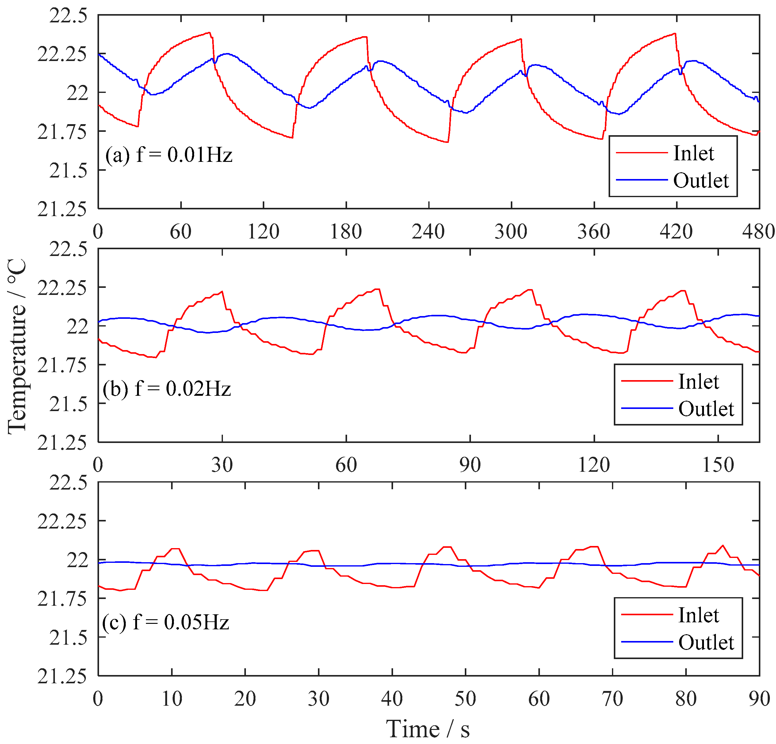
To evaluate the performance of the developed DTFM attenuator, CCW with different temperature fluctuations was introduced as the input of the DTFM attenuator, and the temperature curves of the inlet and outlet of the DTFM attenuator were recorded as shown in Figure 5. The temperature fluctuation of CCW was significantly reduced by the developed DTFM attenuator.
4. Agile Control to Achieve Quick Response and High Regulation Resolution
4.1. Principle
To achieve a quick response and high resolution of CCW temperature control, the agile control of CCW temperature, based on a thermal inertia minimization design and bidirectional regulation of heating/cooling power, was proposed. A thermal inertia minimization design of the cooling module was achieved by using an array of thermoelectric chips (TEC) as cooling elements and building a ‘sandwich’ structure with high heat exchange efficiency. The thermal inertia minimization design of the heating module was achieved based on a structure of ‘solenoid-in-tube’. Bidirectional precision and quick temperature regulation of CCW were achieved through the cooperation of the heating and the cooling modules under the control of a Fuzzy Proportion Integration Differentiation (Fuzzy-PID) algorithm.
4.2. TEC Cooling Module
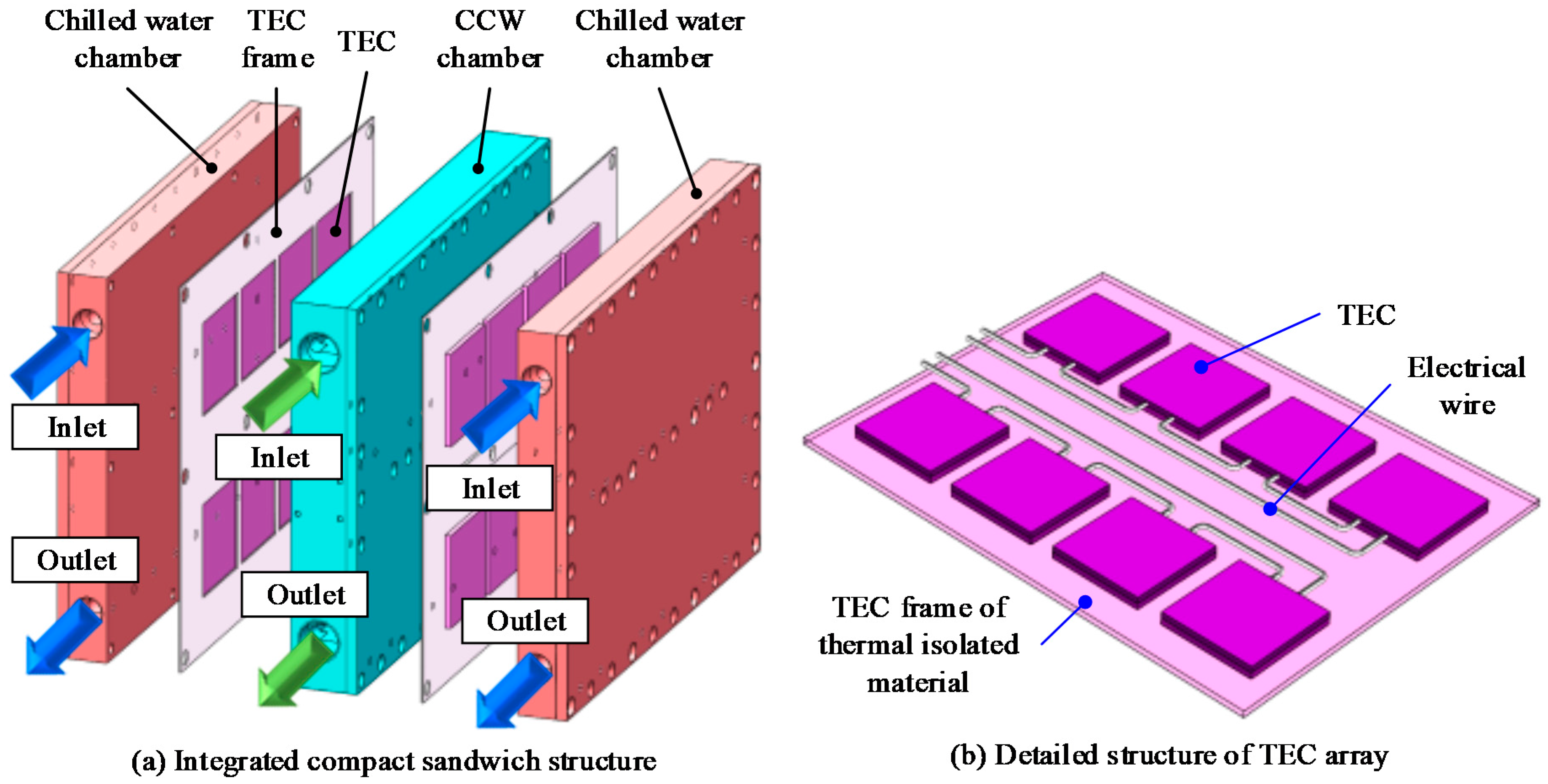
As shown in Figure 6, the cooling module based on TEC presents an integrated compact ‘sandwich’ structure, which was proposed to achieve high cooling efficiency.
A TEC can create a temperature difference between its two sides, when a DC current is applied, and then heating energy is transferred from the cold side to the hot side. Mechanical vibration and noise are avoided, since there are no moving objects in the TEC. Moreover, the cooling power of a TEC increases when the electrical power increases, so it is capable of linear and precision control of cooling power.
As shown in Figure 6, two layers of TEC arrays sandwiched the CCW chamber with the cold sides of TECs. The hot sides of the two TEC arrays were both covered with chilled water chambers. Each TEC array was placed in a frame, which was made of a thermal isolation material to avoid thermal conduction between the two sides of the TECs.
Since aluminum has a large thermal conductivity and low density, the CCW chamber and two chilled water chambers were both made of aluminum alloy, in which the CCW and chilled water traveled along the serpentine waterway to achieve a higher heat exchange efficiency.
Compared to the conventional cooling method, using compressors as cooling elements, the proposed TEC cooling module provided a large cooling power with a compact size, and featured sub-watt level precision and sub-second level response times of cooling power regulation [17,18]. Commercial TEC products (China KJLP, type TEC1-031504040, cooling power of 107 W) were employed as the cooling element of the cooling module. The developed TEC cooling module is 279 mm × 208 mm × 98 mm in size, and can provide a cooling power of 1.5 kW.
4.3. Tube Heating Module
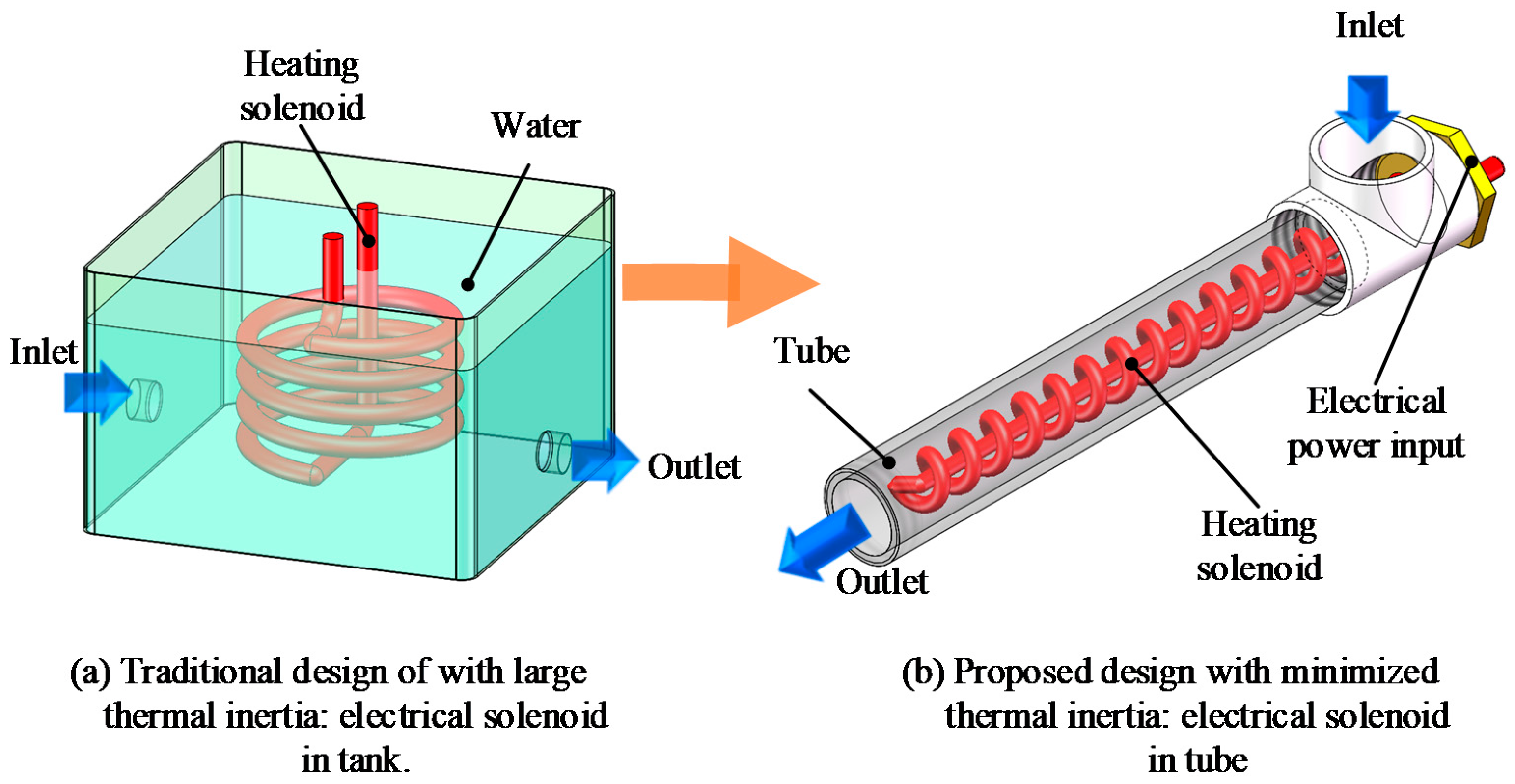
As shown in Figure 7, the heating module based on a ‘solenoid-in-tube’ structure was proposed to achieve minimal thermal inertia. The electrical heating solenoid was assembled in a long thin tube that the CCW flows through. Since the heating solenoid features a sub-second response time, and its heating power is proportional to the electrical power applied, heating power can be controlled with sub-watt level resolution. Compared to conventional heating module design, in which the electrical solenoid is immersed in a water tank, the proposed heating module can achieve agile thermal control. The developed heating module is ϕ 30 mm × 200 mm (diameter × length) in size, and has a maximum heating power of 1.5 kW.
4.4. Control Sub-System
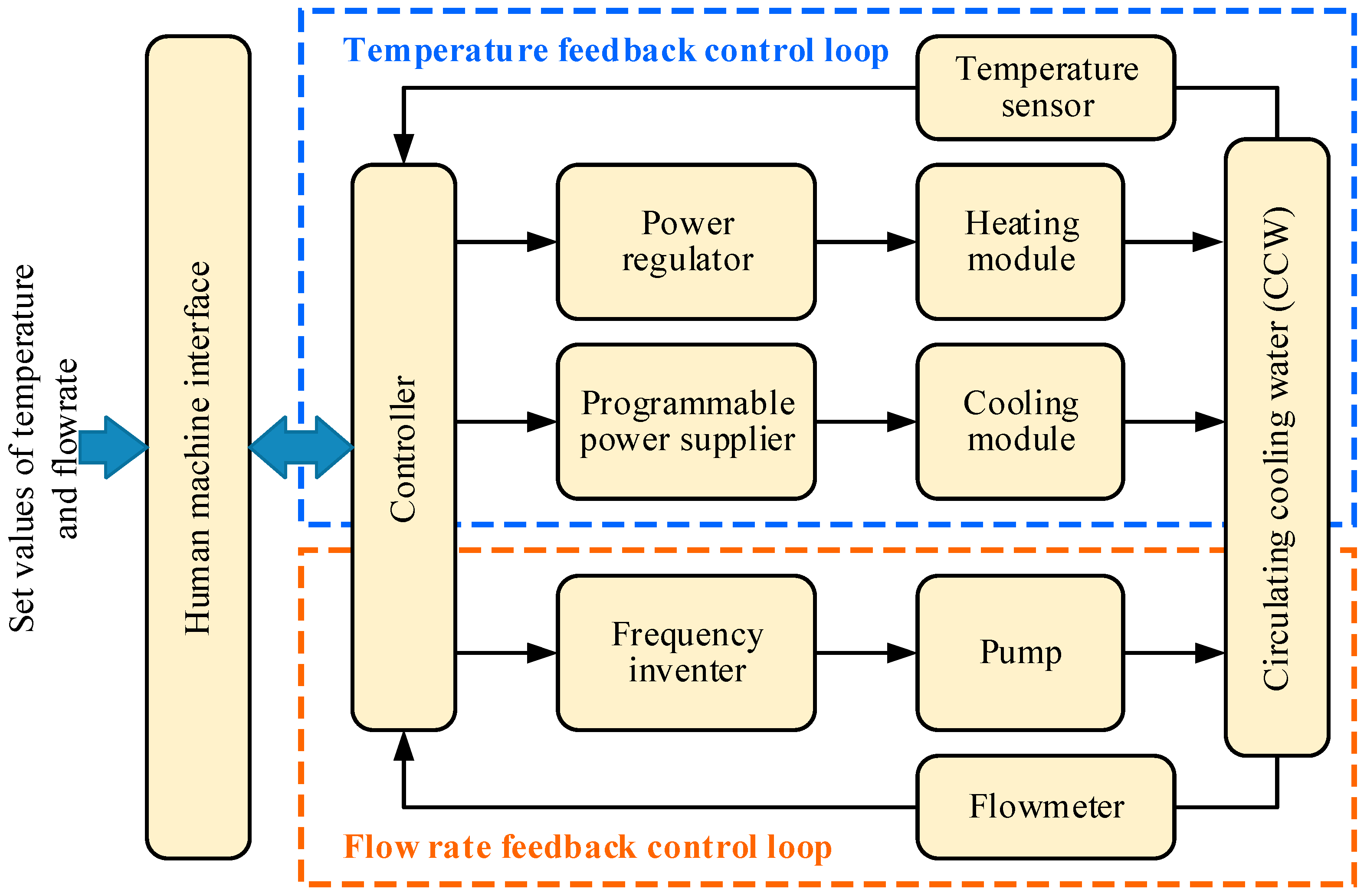
As shown in Figure 8, the control sub-system of the enhanced CCW machine consists of the temperature feedback control loop and the flow rate feedback control loop. The temperature sensor at position A and the flowmeter at position B, as mentioned in Figure 1, provide temperature feedback of CCW, and flow rate feedback of CCW, to the controller, respectively. The heating module is driven by the power regulator, meanwhile, the cooling module is driven by the programmable power supplier.
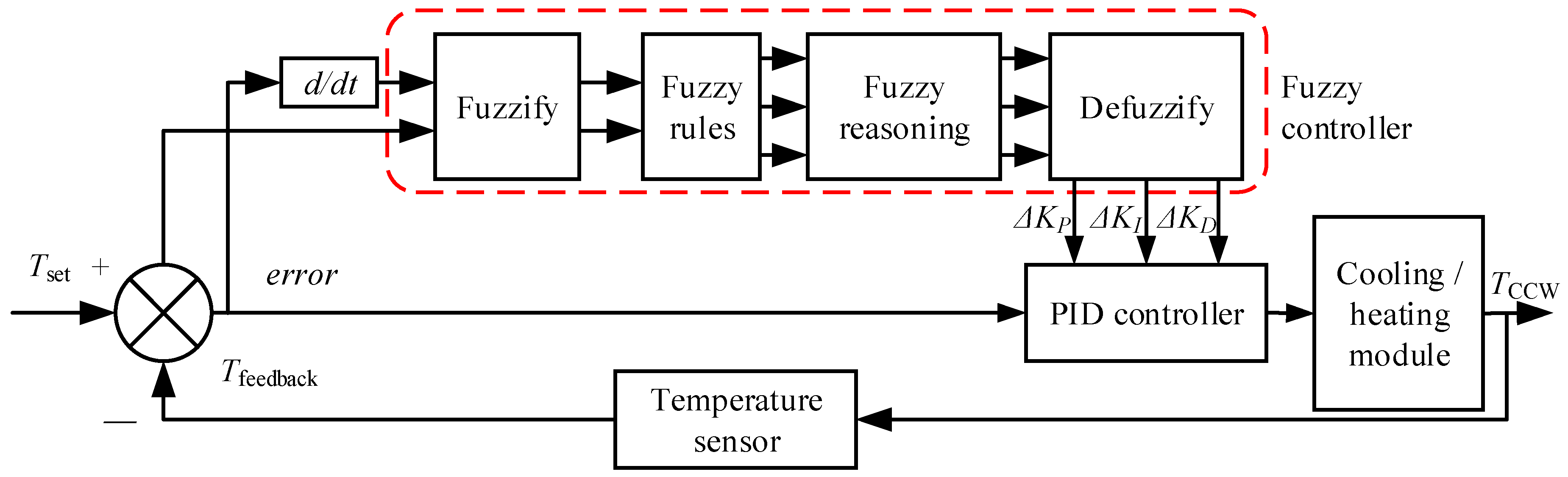
A control algorithm based on a Fuzzy-PID was employed to obtain better performance of CCW temperature control, since the Fuzzy-PID can deal with nonlinearity, time variety, and large time delays of the CCW temperature control system [19], as shown in Figure 9.
Therefore, online PID parameter regulation was achieved by the fuzzy controller to gain better performance of CCW temperature control.
5. Experiments and Discussion
5.1. Experimental Setup
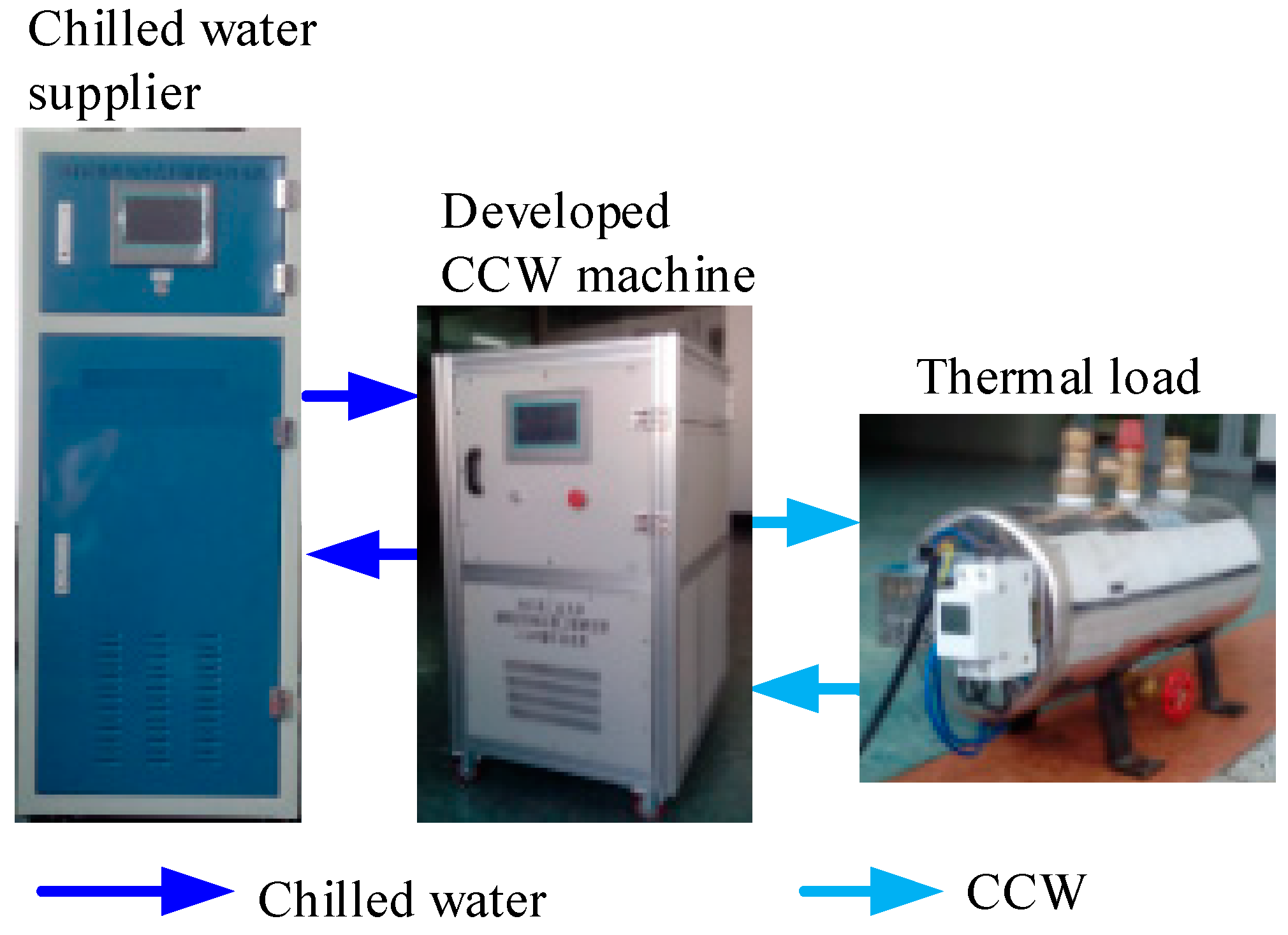
The experimental setup is shown in Figure 10, the developed enhanced CCW machine can provide CCW of temperatures from 12 °C to 40 °C, with a maximum flow rate of 55 L/min. It has a maximum cooling power of 1.5 kW, and a maximum heating power of 1.5 kW. A commercial chilled water supplier was employed to supply chilled water of temperature of 12 °C serving as the cooling source for the system. A programmable heating device with maximum heating power of 1.5 kW served as the thermal load. A high-precision thermistor (Fluke, type 5641, accuracy of ±1 mK, resolution of 0.1 mK, with thermometer Fluke 1560) was employed to measure the temperature of CCW. The experimental setup was located in an air-conditioned machining workshop at 22 °C ± 3 °C.
5.2. Temperature Stability Experiment
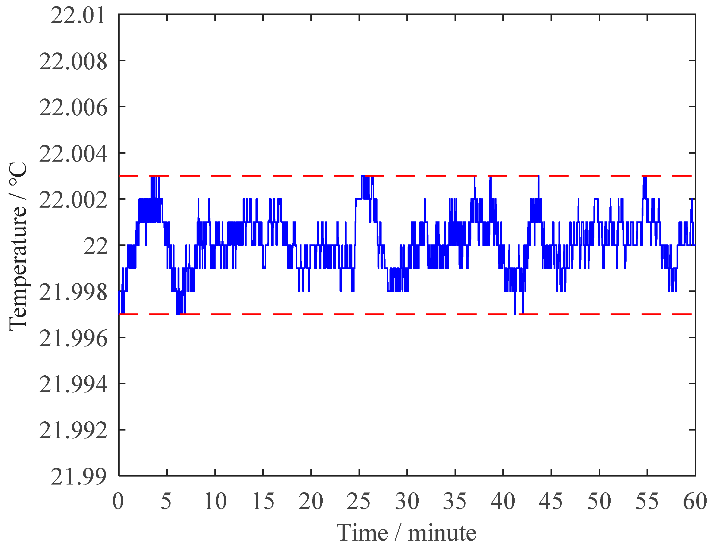
In this experiment, the set value of the CCW temperature was 22 °C, the heating power of the thermal load was 1 kW, and the flow rate of CCW was 15 L/min. The temperature of the CCW was recorded for 60 min with a sampling rate of 1 Hz. Experimental results are shown in Figure 11. It can be seen that, the peak-to-peak value of CCW temperature fluctuation for 60 min was ±3 mK, and its standard deviation was 1.2 mK.
5.3. Dynamic Performance Experiments
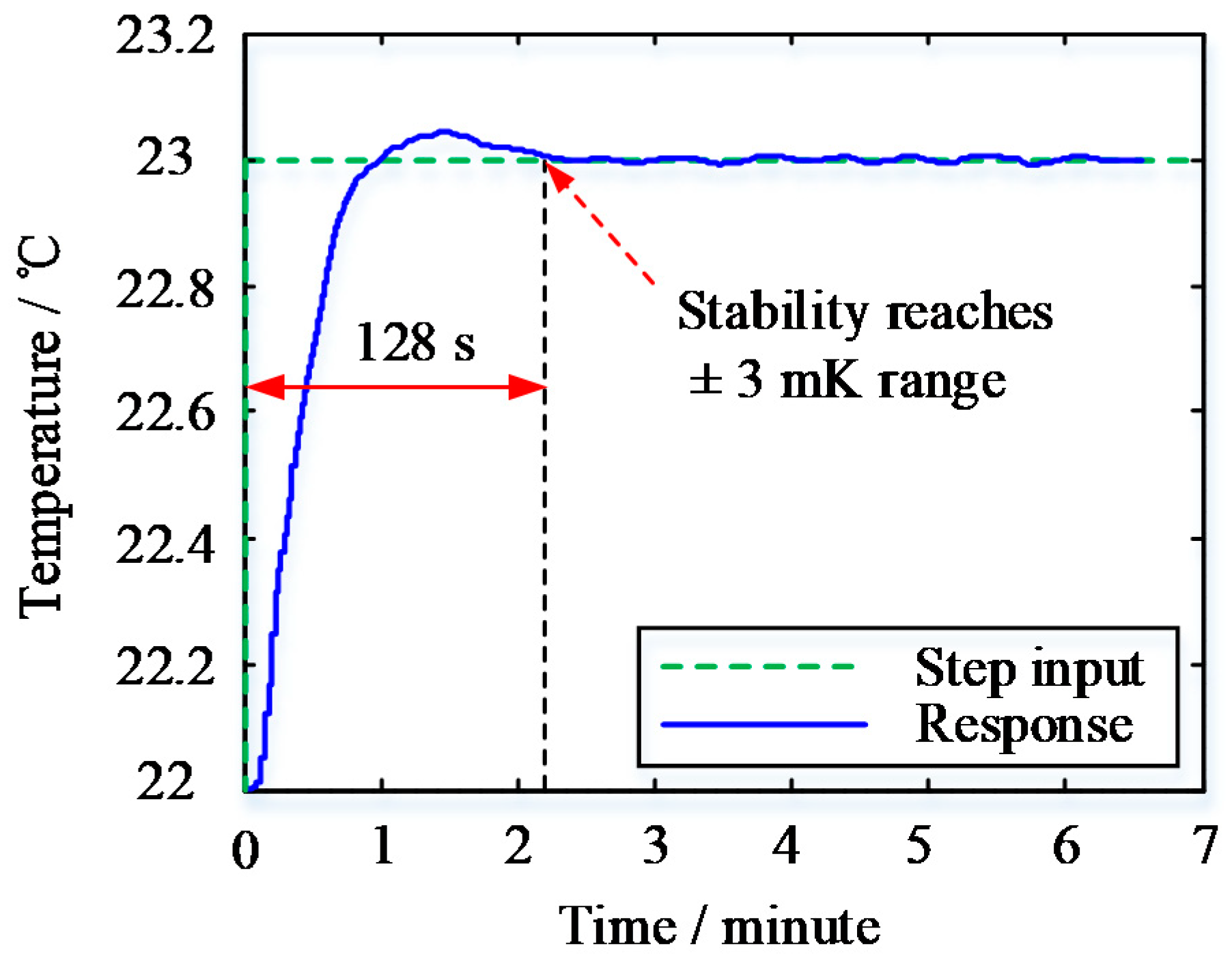
The experiment of 1 K step response of the CCW temperature control was carried out to validate the dynamic performance of the developed CCW machine. The 1 K step of CCW temperature set value was from 22 °C to 23 °C, as shown in Figure 12. Experimental results show that the settling time was 128 s, and the overshoot was 0.03 K.
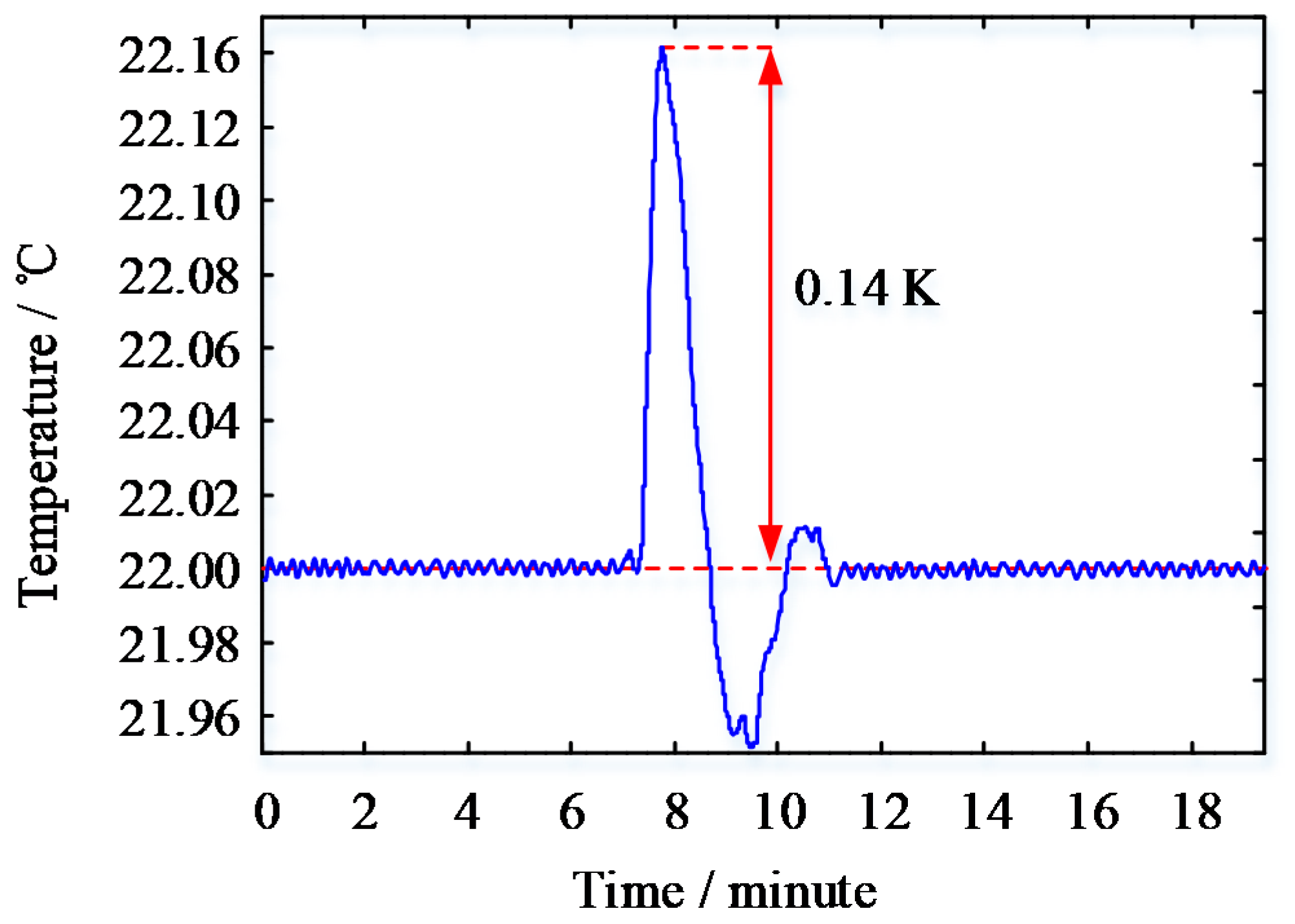
Then, the experiment of thermal impact response was carried out to validate the performance of thermal impact resistance of the developed CCW machine. A 500 W thermal load was introduced by the programmable heating device to make a step thermal impact. Experimental results indicated that the temperature of CCW recovered to a stable state in ~200 s after the thermal impact was introduced, and that the overshoot was about 0.14 K, as shown in Figure 13.
6. Conclusions
In this paper, an enhanced CCW machine, using a dynamic thermal filtering method and agile control, which can accomplish ‘servo thermal management’ for precision manufacturing, is proposed. It can be concluded that:
- (1)
- A dynamic thermal filtering method is proposed. The temperature stability of CCW is significantly improved by the demonstrated temperature fluctuation attenuator, based on the proposed method, while the dynamic performance of the CCW temperature control is not degraded. According to the concept of agile control, a thermoelectric cooling module, with a compact multilayer sandwich structure, as well as a heating module with a ‘solenoid-in-tube’ structure, are proposed, and thus the thermal inertia of the modules is minimized. Furthermore, bidirectional regulation of thermal power is realized with the proposed cooling and heating modules, based on the control of Fuzzy-PID. Therefore, the excellent dynamic performance of CCW temperature control is achieved.
- (2)
- Experiments were carried out to validate the performance of the enhanced CCW machine. The temperature stability was ±3 mK (peak-to-peak value), and its standard deviation was 1.2 mK. The settling time was 128 s, and the overshoot was 0.03 K for 1 K step of the set value of CCW temperature. The CCW temperature had a good performance against thermal impact.
Our following work will focus on the further improvement of the dynamic performance of the CCW machine, and the shortening of the response time of dozens of seconds.
Author Contributions
Conceptualization, Y.L., J.C. and J.T.; Funding acquisition, J.C. and J.T.; Investigation Y.L.; Methodology, J.C. and J.T.; Project administration, J.C. and J.T.; Resources, Y.L.; Visualization, X.B.; Writing—original draft, Y.L.; Writing—review & editing, Y.L., J.C. and J.T. All authors have read and agreed to the published version of the manuscript.
Funding
This research was funded by National Natural Science Foundation of China, grant number 51675139 and the Fundamental Research Funds for the Central Universities.
Conflicts of Interest
The authors declare no conflicts of interest.
References
- Mayr, J.; Jedrzejewski, J.; Uhlmann, E.; Donmez, M.A.; Knapp, W.; Härtig, F.; Wendt, K.; Moriwaki, T.; Shore, P.; Schmitt, R.; et al. Thermal issues in machine tools. CIRP Ann. 2012, 61, 771–791. [Google Scholar] [CrossRef] [Green Version]
- Zhao, Y.; Trumper, D.L.; Heilmann, R.K.; Schattenburg, M.L. Optimization and temperature mapping of an ultra-high thermal stability environmental enclosure. Precis. Eng. 2010, 34, 164–170. [Google Scholar] [CrossRef]
- Manske, E.; Jäger, G.; Hausotte, T.; Füßl, R. Recent developments and challenges of nanopositioning and nanomeasuring technology. Meas. Sci. Technol. 2012, 23, 074001. [Google Scholar] [CrossRef]
- Yamada, A. ArF immersion lithography for 45nm and beyond. In Proceedings of the SPIE—The International Society for Optical Engineering, Yukohama, Japan, 17–19 April 2007; Volume 6607, pp. 66071–66081. [Google Scholar]
- Tay, A.; Chua, H.T.; Wang, Y.; Ngo, Y.S. Equipment design and control of advanced thermal-processing module in lithography. IEEE Trans. Ind. Electron. 2009, 57, 1112–1119. [Google Scholar] [CrossRef]
- Chou, C.; DeBra, D.B. Liquid temperature control for precision tools. CIRP Ann. 1990, 39, 535–543. [Google Scholar] [CrossRef]
- Cui, L.Y.; Zhang, D.W.; Gao, W.G.; Qi, X.Y.; Shen, Y. Thermal errors simulation and modeling of motorized spindle. Adv. Mater. Res. 2010, 154, 1305–1309. [Google Scholar] [CrossRef]
- Lawton, K.M.; Patterson, S.R.; Keanini, R.G. Precision temperature control of high-throughput fluid flows: Theoretical and experimental analysis. J. Heat Transf. 2001, 123, 796–802. [Google Scholar] [CrossRef]
- Lawton, K.M.; Patterson, S.R.; Keanini, R.G. Direct contact packed bed thermal gradient attenuators: Theoretical analysis and experimental observations. Rev. Sci. Instruments 2003, 74, 2886–2893. [Google Scholar] [CrossRef] [Green Version]
- Oró, E.; De Gracia, A.; Castell, A.; Farid, M.; Cabeza, L.F. Review on phase change materials (PCMs) for cold thermal energy storage applications. Appl. Energy 2012, 99, 513–533. [Google Scholar] [CrossRef]
- Charvat, P.; Klimes, L.; Stetina, J.; Ostry, M. Thermal storage as a way to attenuate fluid-temperature fluctuations: Sensible-heat versus latent-heat storage materials. Mater. Tehnol. 2014, 48, 423–427. [Google Scholar]
- Alawadhi, E.M. Temperature regulator unit for fluid flow in a channel using phase change material. Appl. Therm. Eng. 2005, 25, 435–449. [Google Scholar] [CrossRef]
- Unni, P.K.M.; Gunasekaran, M.K.; Kumar, A. ±30 μK temperature controller from 25 to 103 °C: Study and analysis. Rev. Sci. Instrum. 2003, 74, 231–242. [Google Scholar] [CrossRef]
- Mann, G.; Hu, B.-G.; Gosine, R. Analysis of direct action fuzzy PID controller structures. IEEE Trans. Syst. Man Cybern. Part B Cybern. 1999, 29, 371–388. [Google Scholar] [CrossRef] [PubMed]
- Lim, H.S.; Kang, Y.T. Optimization of influence factors for water cooling of high temperature plate by accelerated control cooling process. Int. J. Heat Mass Transf. 2019, 128, 526–535. [Google Scholar] [CrossRef]
- Liu, T.; Gao, W.; Tian, Y.; Zhang, H.; Chang, W.; Mao, K.; Zhang, D. A differentiated multi-loops bath recirculation system for precision machine tools. Appl. Therm. Eng. 2015, 76, 54–63. [Google Scholar] [CrossRef] [Green Version]
- Enescu, D.; Virjoghe, E.O. A review on thermoelectric cooling parameters and performance. Renew. Sustain. Energy Rev. 2014, 38, 903–916. [Google Scholar] [CrossRef]
- Sun, K.; Qiu, Z.; Wu, H.; Xing, Y. Evaluation on high-efficiency thermoelectric generation systems based on differential power processing. IEEE Trans. Ind. Electron. 2018, 65, 699–708. [Google Scholar] [CrossRef]
- Huang, C.-W.; Pan, S.-T.; Zhou, J.-T.; Chang, C.-Y. Enhanced temperature control method using ANFIS with FPGA. Sci. World J. 2014, 2014, 1–8. [Google Scholar] [CrossRef] [PubMed]
Figure 1.
Scheme of an enhanced circulating cooling water (CCW) machine.

Figure 2.
Scheme of an attenuator based on a dynamic thermal filtering method.

Figure 3.
Three-dimensional structure of the tube-tank heat exchanger.

Figure 4.
Modeling results of the temperature fluctuation ratio of the dynamic thermal filtering method (DTFM) attenuator.
Figure 4.
Modeling results of the temperature fluctuation ratio of the dynamic thermal filtering method (DTFM) attenuator.

Figure 5.
Modeling results of the temperature fluctuation ratio of the DTFM attenuator.

Figure 6.
Scheme of the thermoelectric chip (TEC) cooling module.

Figure 7.
Scheme of the tube heating module.

Figure 8.
Schematic diagram of the control sub-system of the enhanced CCW machine.

Figure 9.
Schematic diagram of Fuzzy Proportion Integration Differentiation (Fuzzy-PID) introduced in the enhanced CCW machine.
Figure 9.
Schematic diagram of Fuzzy Proportion Integration Differentiation (Fuzzy-PID) introduced in the enhanced CCW machine.

Figure 10.
Experimental setup.

Figure 11.
Experimental results of CCW temperature stability.

Figure 12.
Experimental results of 1 K step response.

Figure 13.
Experimental results of the 500 W thermal load impact response.


Table 1.
Parameters of the tube-tank heat exchanger and CCW.
| Symbol | Parameter | Quantity and Unit |
|---|---|---|
| L | Length of tube | 0.7 m |
| Rtube | Diameter of tube | 8 mm |
| a | Center spacing between neighboring tubes | 32 mm |
| N | Number of tubes | 36 |
| b | Width of tank | 0.23 m |
| l | Height of tank | 0.7 m |
| La | Height of accumulator | 0.05 m |
| Ld | Length of distributor | 0.05 m |
| Fm | Total flow rate | 16 L/min |
© 2020 by the authors. Licensee MDPI, Basel, Switzerland. This article is an open access article distributed under the terms and conditions of the Creative Commons Attribution (CC BY) license (http://creativecommons.org/licenses/by/4.0/).
Share and Cite
MDPI and ACS Style
Lu, Y.; Cui, J.; Tan, J.; Bian, X. Quick Response Circulating Water Cooling of ±3 mK Using Dynamic Thermal Filtering. Appl. Sci. 2020, 10, 5483. https://doi.org/10.3390/app10165483
AMA Style
Lu Y, Cui J, Tan J, Bian X. Quick Response Circulating Water Cooling of ±3 mK Using Dynamic Thermal Filtering. Applied Sciences. 2020; 10(16):5483. https://doi.org/10.3390/app10165483
Chicago/Turabian StyleLu, Yesheng, Junning Cui, Jiubin Tan, and Xingyuan Bian. 2020. "Quick Response Circulating Water Cooling of ±3 mK Using Dynamic Thermal Filtering" Applied Sciences 10, no. 16: 5483. https://doi.org/10.3390/app10165483
Note that from the first issue of 2016, this journal uses article numbers instead of page numbers. See further details here.