Effect of the Directional Components of Earthquakes on the Seismic Behavior of an Unanchored Steel Tank

1
College of Pipeline and Civil Engineering, China University of Petroleum, Changjiang West Road No. 66, Qingdao 266580, China
2
School of Civil Engineering and Architecture, Xiamen University of Technology, Ligong Road No. 600, Xiamen 361000, China
*
Author to whom correspondence should be addressed.
Appl. Sci. 2020, 10(16), 5489; https://doi.org/10.3390/app10165489
Submission received: 9 July 2020
/
Revised: 3 August 2020
/
Accepted: 5 August 2020
/
Published: 8 August 2020
(This article belongs to the Special Issue Structural and Earthquake Engineering)
Abstract
:This paper investigates the effect of the multi-directional components of ground motion on an unanchored steel storage tank. Both the liquid sloshing effect and contact behavior between the foundation and tank are included in the study. A three-dimensional model for a foundation–structure–liquid system is numerically simulated using the finite element method. The Lagrange fluid finite element method (FEM) in ANSYS is used to consider the liquid–solid interaction. In the liquid–structure–foundation interaction model, the contact and target elements are adapted to simulate the nonlinear uplift and slip effects between the tank and the foundation. Three earthquake ground motions are selected for evaluating the seismic behavior of the tank. Comparisons are made on the horizontal displacement, “elephant-foot” deformation, stress, base shear and moment, sloshing of the liquid, uplift, as well as slip behavior under the application of the unidirectional, bi-directional and tri-directional components. Under the selected ground motions, the horizontal bi-directional seismic component has great influence on the liquid sloshing in the tank studied in this paper. The vertical seismic component produces high compressive axial stress, and it also makes the uplift and slide of the tank bottom increase significantly. The applicability of this conclusion should be carefully considered when applied to other types of ground motion inputs.
1. Introduction
Aboveground storage tanks are a very important part of industry, mainly used in water supply, nuclear power plants, oil refineries, and petrochemical facilities. The importance of the tank often exceeds its economic cost, because the impact of its failure is not only limited to the risk of nearby personnel and equipment, but also may cause serious consequences to the environment [1]. Storage tanks, specially unanchored tanks, indicated their seismic vulnerability in previous earthquakes, including the 1983 Coalinga earthquake. Some tanks were seriously damaged, and some tanks failed, resulting in disastrous consequences [2,3]. Therefore, it is very important to ensure the reliability of their operation, as many of them are located in areas of the world where seismic activity is frequent.
Earthquake observations and multiple earthquake damage investigations have shown that earthquakes do not involve one-dimensional motions but rather multi-dimensional random vibrations. The ground motions of seismic waves are often extremely complex, and the damage to various structures are often attributed to multi-dimensional ground motion. In recent years, scholars have become more interested in the dynamic behavior of structures under multi-dimensional excitation. These studies [4,5] discussed the effect of multi-directional ground motion on the earthquake response of the structures, and the results show that the structure response under multi-directional excitation will increase and this impact cannot be neglected.
Unanchored tanks involve geometrical and physical boundary problems and the multi-nonlinear dynamic coupling uplift problem. Presently, few studies concentrate on the uplift mechanism of unanchored storage tanks and the relationship between the mechanism and destabilization and strength destruction. Many studies focused on the influence of multi-directional seismic wave excitation on civil building structures, while the seismic studies of storage tanks mainly consider the influence of only the unidirectional horizontal seismic component on the seismic response of storage tanks. The combined effects of the three mutually perpendicular components of earthquakes are generally neglected in the dynamic analysis of storage tanks. Haroun et al. [6] studied the seismic behavior of cylindrical storage tanks subjected to a vertical component of seismic excitation. Ghaemmaghami et al. [7] evaluated the effect of wall flexibility on the earthquake response of a rectangular tank under horizontal and vertical excitations. The results show that the vertical seismic component contributes to the dynamic response of the tank and cannot be ignored. Sobhan et al. [8] investigated the static and dynamic buckling of an anchored steel tank under horizontal and vertical ground accelerations. The buckling capacity of the tank was estimated by static pushover and incremental dynamic analysis. According to the research of Haroun et al. [9,10,11], the performance of a ground tank under vertical excitation is closely related to their seismic design, because the vertical acceleration is transferred to the horizontal hydrodynamic load on the tank wall. This effect mainly leads to an increase in the circumferential tensile stress and the influence of horizontal input, which leads to the inelastic buckling of the shell. Bakalis et al. [12] presents a simplified method to evaluate the seismic performance of liquid storage tanks. The method relies on nonlinear static analysis and can be combined with the appropriate “strength ratio–ductility–period” relationship to obtain the relevant structural requirements of the required seismic intensity range. Colomboa et al. [13] proposed a simplified nonlinear model for three-dimensional dynamic analyses, and used the model to study the partially uplifted base plates of two kinds of thin-walled cylindrical tanks (one is a slender tank and the other is a wide tank). It is found that both anchored and unanchored tanks may produce a high compressive axial stress. On 31 March 2006, the devastating earthquake in western Iran caused damage to some unanchored tanks. To estimate the actual performance of the tank, Miladi et al. [14] uses ABAQUS software to analyze the failure of the most seriously damaged unanchored tank with a diameter of 3.8 m and liquid height of 4.2 m. Under the Silakhor earthquake components recorded at the Chalanchulan station, the results show that the critical PGA of the dynamic buckling is 0.285 g, and the critical PGA is limited for the analyzed tank structure.
Most of the mentioned studies analyzed only the vertical component, which is different from the actual conditions. Furthermore, due to the differences in earthquake characteristics, tank size, and calculation theory, there is still no consensus about the effect of vertical excitation on the seismic response of the storage tank. This present study used the numerical simulation method to establish an unanchored tank model based on ANSYS software, considering the combined actions of the horizontal and vertical components of ground motion. In order to be closer to the actual situation, the contact effect between the tank bottom and foundation is considered, and the influence of the multi-dimensional ground motion on the stress and deformation of the tank was obtained under different calculation conditions.
2. Modelling of Fluid-Tank-Foundation System Based on Lagrangian Approach
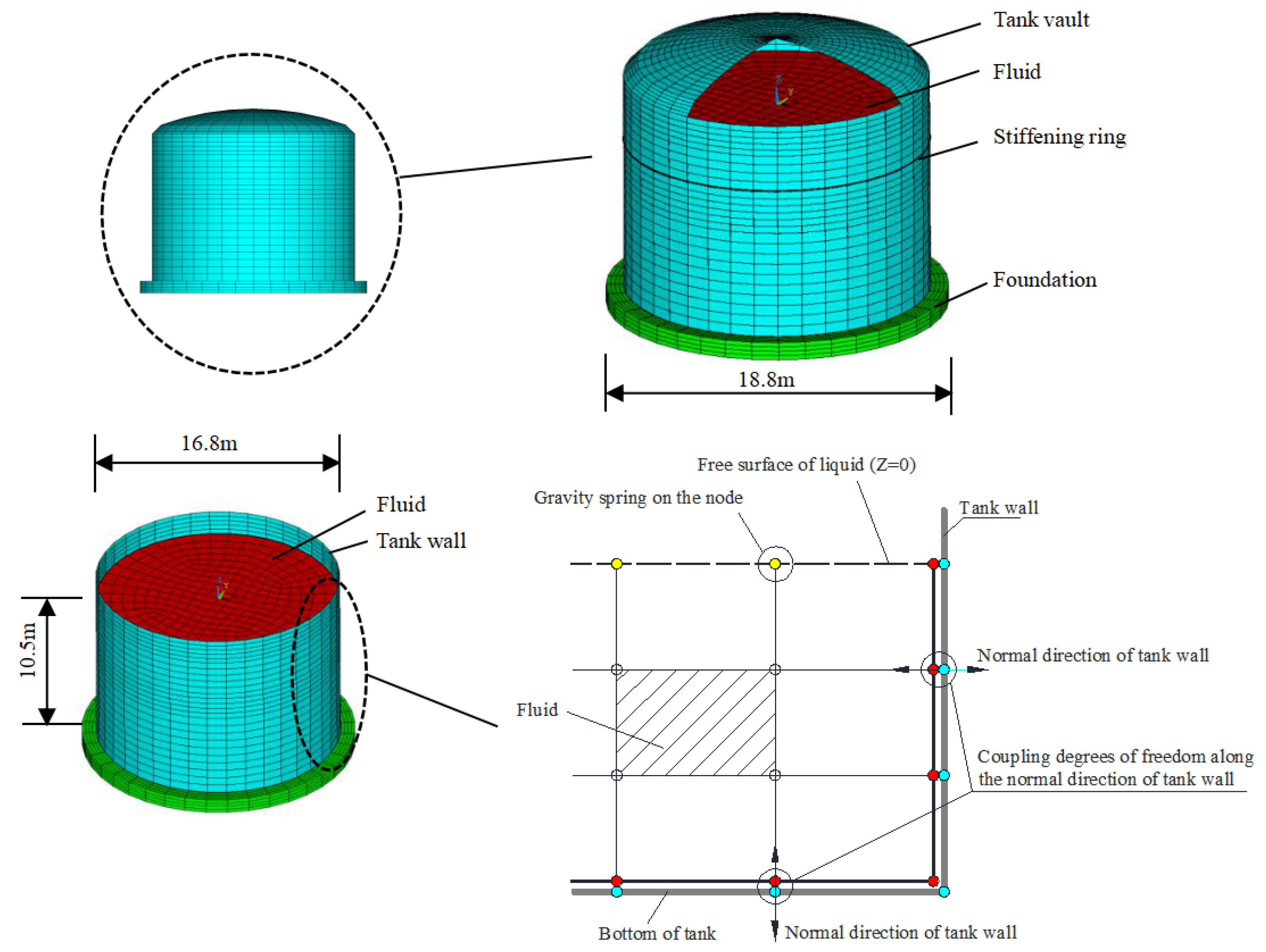
Fluid–structure interaction problems can be investigated by different methods, such as the added mass method, Lagrangian method, Eulerian method, and Lagrangian–Eulerian method. In this study, the displacement-based Lagrangian method is selected to simulate the interaction of the tank and fluid. The fluid element is defined by eight nodes, and each node has three degrees of freedom: translation in the X, Y, and Z directions of the node. Because of the lack of geometric capability in the Lagrangian finite element method considering the brick elements, the intze-type is idealized as a cylindrical vessel that has the same capacity with the intze-type [15]. When the fluid in the tank structure vibrates, the free surface always tends to the equilibrium position under the action of gravity. To simulate the effect of the restoring force on the free surface of the fluid, an additional spring must be considered in the free demonstration. A special surface effect should be considered when selecting the fluid element option; that is, adding a gravity spring to each node to restore the surface to the equilibrium position, as shown in Figure 1. The parameters of the gravity spring are positive at the top of the element and negative at the bottom of the element. If there is a free surface, the gravity effect must be included. For internal nodes, the positive and negative effects cancel each other. At the bottom, the fluid must be contained to prevent fluid leakage, and the negative spring does not work (as long as all degrees of freedom at the bottom are fixed) [16].
The positive stiffness of the spring can be described as
where is the mass density, is the surface area of the component, and and are the acceleration in the direction of the i and ith component of the normal to the face of the element, respectively.
The mass and stiffness matrix of the fluid element can be expressed as
where is the interpolating function, , and are the weight functions, is the Jacobian matrix, is the strain-displacement matrix, and can be computed from .
The equations of kinetic energy and potential energy can be given as
Substituting the above expressions of kinetic energy and potential energy into the Lagrange equation gives
where uj is the jth displacement component and Fj is the external load applied to the system.
The governing equation of the system can be expressed as
where is the acceleration and is a general time-varying load vector.
If the effect of foundation is included, the governing equation of the motion of the foundation–tank–fluid system under the ground motions can be given as follows
where is the mass matrix, is the stiffness matrix, is the damping matrix, and subscripts st, f, and s indicate the structure–foundation, fluid, and fluid surface of the fluid–structure system, respectively. is the input seismic acceleration. The above governing equation of motion can be directly solved using the Newmark method, a stepwise numerical integration method. More details can be found in [15].
3. Description of the Steel Storage Tank
3.1. Parameters of the Steel Storage Tank Material
The analyzed object in this study is a steel tank with a vault. The whole storage tank model includes three parts: the tank body, the liquid, and the foundation. The material of the steel tank is S235. The inner radius of the tank is 8.4 m, and the height is 12.24 m. The height-to-diameter ratio (H/D) of the tank is 0.73. The thickness of the tank varies along the height of the tank. The closer to the bottom, the thicker the wall. The thickness of the tank is divided into four types from the bottom to the top: 12 mm, 10 mm, 8 mm, and 6 mm. For the vault, the height is 2.06 m and the thickness is 6 mm. In order to improve the stability of the tank body, a reinforcing ring is adapted along the circumference of the tank wall at a height of 8.5 m from the tank bottom. The reinforcing ring is made of hot-rolled unequal angle steel S235 L100 × 63 × 8. Young’s modulus and the density of the steel tank are taken to be 2.06 × 10⁵ MPa and 7800 kg/m3, respectively. The behavior of the steel tank structure is considered to be linear elastic in the dynamic analysis.
The tank may be in a more dangerous state when the liquid is full. In the analysis, the tank is filled with water with a density of 1000 kg/m3. The height of the liquid is 10.5 m, so the tank is almost full of liquid. When modeling, the foundation is simplified as a circular concrete plate with a radius of 9.4 m and a thickness of 1.0 m. The elastic modulus of the material is 3.0 × 10⁴ MPa. The dynamic friction coefficient value assumed in the numerical model is 0.2. The soil–structure interaction is neglected in the study. The seismic waves are applied directly at the bottom of the foundation.
As shown in Figure 1, a finite element model was built based on the software ANSYS [16] to simulate the fluid–tank–foundation system, and a transient dynamic analysis was carried out to determine the seismic behavior of the tank. In the finite element model, the Shell181 element was used to characterize the tank wall and bottom plate. The Fluid80 element was assumed to be incompressible fluid, in which the fluid elements are especially formulated to simulate fluid without a net flow in the container. The Beam188 element is used for the reinforcing ring. The mesh of the reinforcement ring is coordinated with the tank wall mesh. A nonlinear dynamic analysis was carried out to observe the seismic response of the liquid–storage tank.
3.2. Coupling Setting between Tank and Fluid
Under the strong earthquake action, the liquid in the tank will hit the tank wall, causing a discernible sloshing response at the tank wall. In order to simulate the actual situation, the coupling relationship between the fluid and tank wall is established in the finite element model. The degrees of freedom of the nodes on the liquid and the tank are coupled along the normal direction of the tank wall. In this study, two coincident nodes are generated at the same position at the interface of the tank and liquid. One node belongs to the fluid element, and the other node belongs to the shell element. For each position in the interface, the two nodes have the same normal displacements, but their tangential displacements are not coupled. At the tank bottom, the fluid can also move horizontally to maintain the displacement coordination while allowing the relative slide in the tangential direction, as shown in Figure 1. This operation ensures that the liquid will not pass through the tank wall and can shake freely along the tank wall.
3.3. Consideration of Contact Effect between Tank and Foundation
The unanchored tank may not offset the overturning force caused by the strong earthquake, meaning uplift and slip will occur at the tank bottom. The overturning resistance of unanchored tanks strongly depends on the height-to-diameter ratio of the tank. The outer edge of the bottom plate is lifted and separated from the foundation. Therefore, the contact effect between the tank bottom and foundation should be considered. According to the contact condition between the tank bottom and foundation, the contact elements and target elements matching the shell and solid elements are adopted. Target elements are present at the tank bottom, and the contact elements are provided on the foundation surface. The contact elements and target elements are used to simulate the non-linearity of the moving boundary between the bottom plate and platform, and the nonlinear lifting and sliding of the bottom of the tank are realized. So, the calculation in this study belongs to the nonlinear dynamic analysis.
4. Numerical Calculation Results and Analysis
4.1. Modal Results Analysis
In modal analysis, due to the requirements of the finite element software for the fluid element, it is necessary to set master–slave degrees of freedom for the fluid element. On a fluid-free surface, the degrees of freedom in the normal direction are defined as the primary degree of freedom, and the remaining degrees of freedom are defined as the slave degrees of freedom. In the coupling alignment of the nodes on the fluid–solid interface, only the first degree of freedom can be defined as the master degree of freedom, and the rest are the slave degrees of freedom.
The sloshing characteristics and mode shapes are important parameters in a dynamic analysis. The determination of these parameters can be very useful in describing the tank’s behavior. The vibration modes of the liquid storage tank are classified roughly into convective and impulsive. The convective mode and impulsive mode are the most important vibration modes that have the maximum mass contribution effects. This modal analysis can be used as the starting point of the time history analysis.
To perform the verification of the model, the numerical results are compared with results of a theoretical formula and standard formula. The basic frequency of the liquid sloshing and the basic frequency of the coupling vibration of the tank were obtained by modal analysis. The theoretical formulas for the basic frequency fw of the liquid convective oscillation and the basic frequency fc of the coupling vibration of the tank and liquid are given in [17]. In China, the code of the “vertical cylindrical steel welded tank design” (GB50341-2014) [18] also provides the formulas for fw and fc. The results comparison of the numerical calculation, theoretical formulas, and recommended formulas in the code are listed in Table 1.
The fundamental frequencies of the liquid sloshing and the liquid–structure coupling vibration calculated in this paper are 0.228 Hz and 7.046 Hz, respectively. The calculated values are highly similar to those obtained using the proposed method, with the maximum error of 5.56% only. Thus, the analytical model established in this paper is validated. Rayleigh damping is used for the subsequent seismic behavior of the liquid–structure system. The damping ratio is 2% for impulsive mass, and the damping ratio is 0.5% for convective mass (damping for water).
4.2. Ground Motion Records Used for Dynamic Calculation
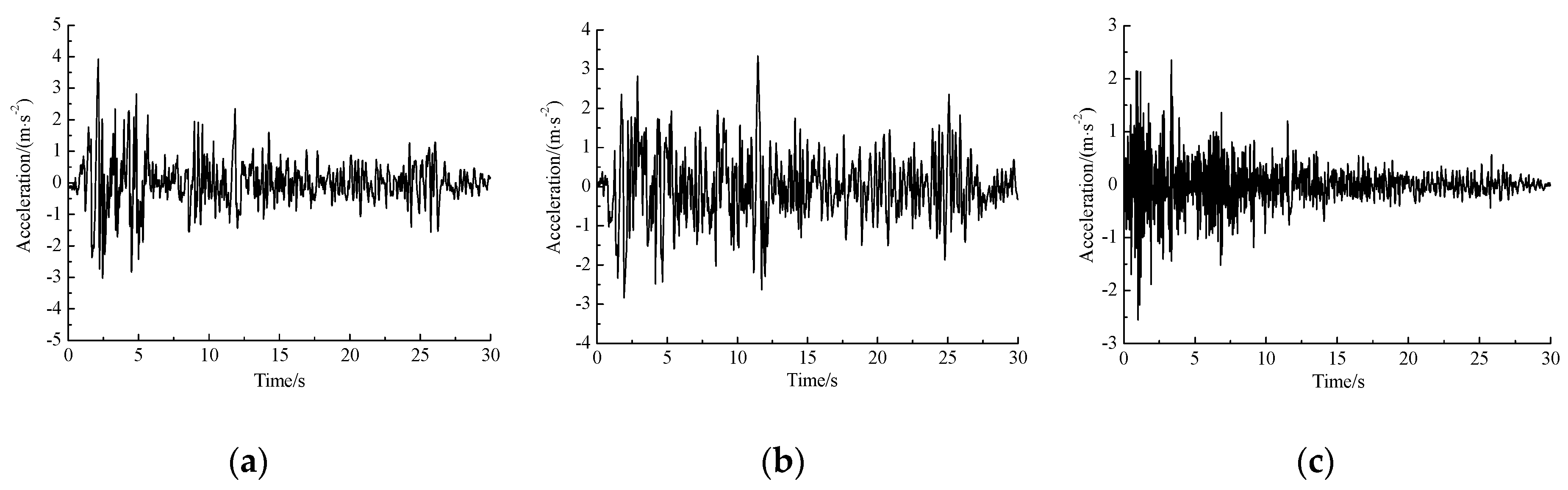
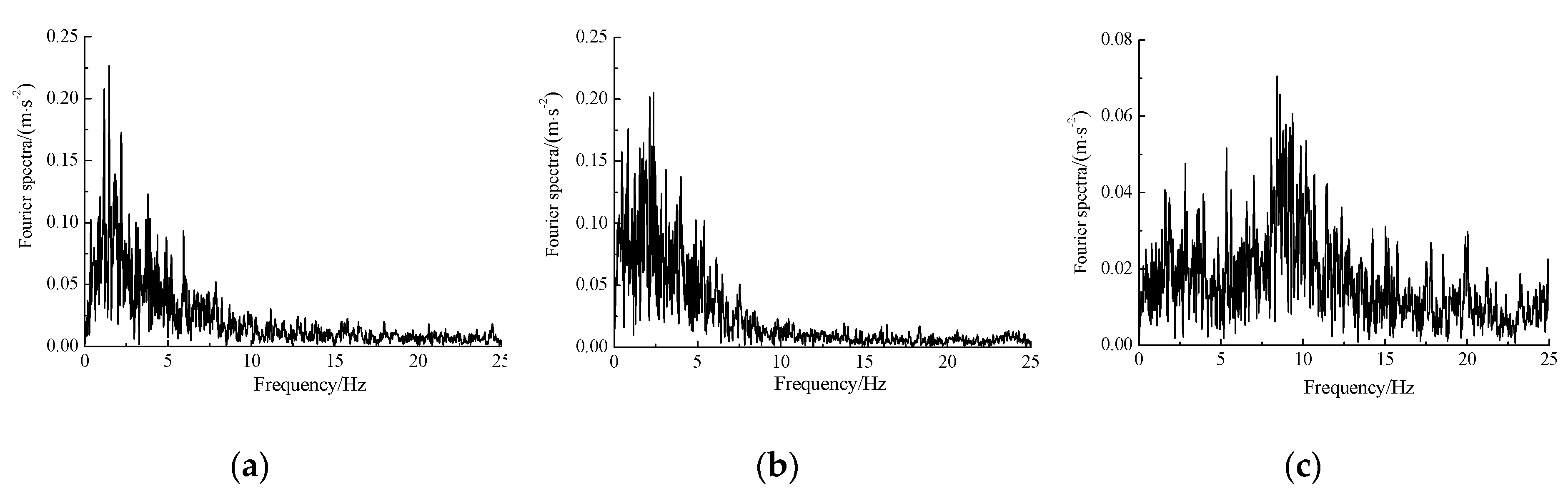
Three earthquake ground motions are selected for the present study. Table 2 shows the characteristics of the three earthquake ground motions along with their corresponding peak ground acceleration (PGA) in terms of g. According to the Chinese code for seismic design of buildings, the horizontal X-direction component amplitude is adjusted to 0.4 g, the horizontal Y-direction component amplitude is adjusted to 0.34 g, and the vertical Z direction component amplitude is adjusted to 0.26 g. The three components of the El Centro ground motion are present in Figure 2 in terms of m/s2. The corresponding Fourier spectrum curves of the three seismic waves are shown in Figure 3.
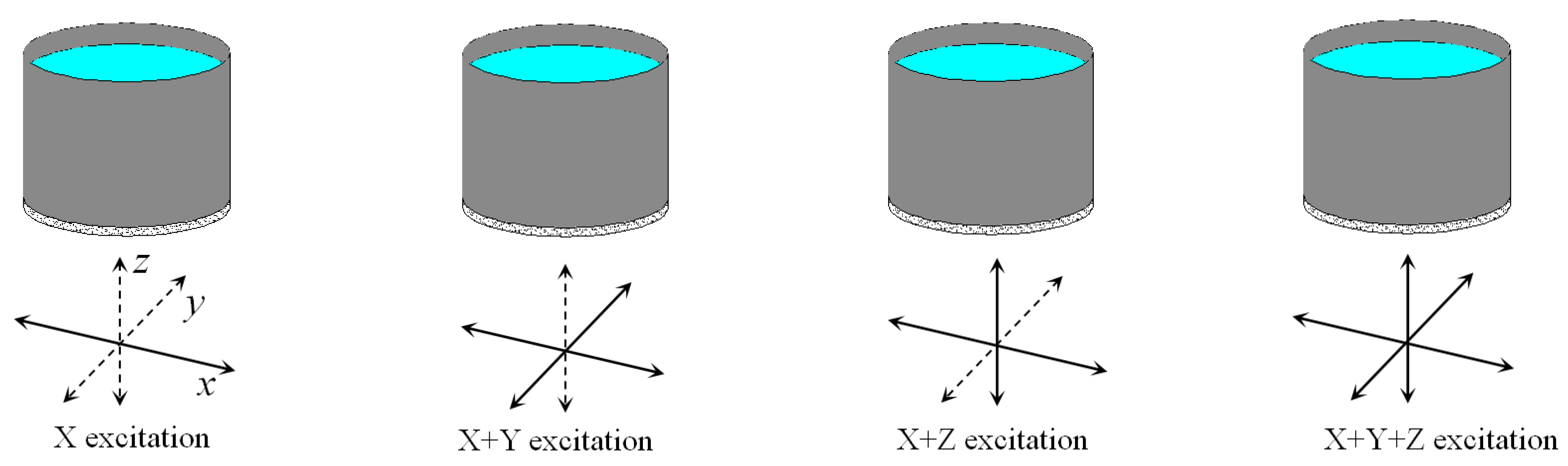
For comparison purposes, the base excitation was applied along the unidirectional (Referred to as “X”), horizontal bi-directional (Referred to as “X + Y”), horizontal and vertical bi-directional (Referred to as “X + Z”), and tri-directional (Referred to as “X + Y + Z”) components of the earthquake, as shown as Figure 4.
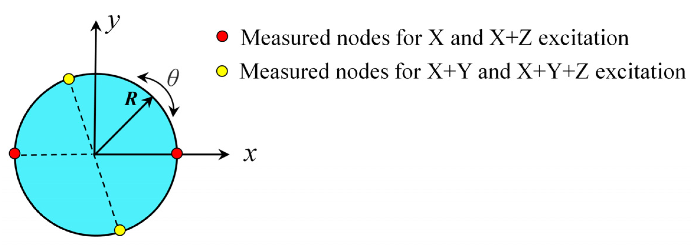
For each case, the location with the largest seismic response can be found as the observation point on a certain height by cycling along the tank circumference. For the X excitation and X + Z excitation, the peak response quantities are measured at the nodes on the plane where the XOZ plane intersects the tank wall; that is, along the X-direction (θ = 0°). For the X + Y excitation and X + Y + Z excitation, the nodes of the peak response quantities on the tank wall will change due to the Y-directional component, as shown in Figure 5.
4.3. Discussion of Seismic Time-History Response Results
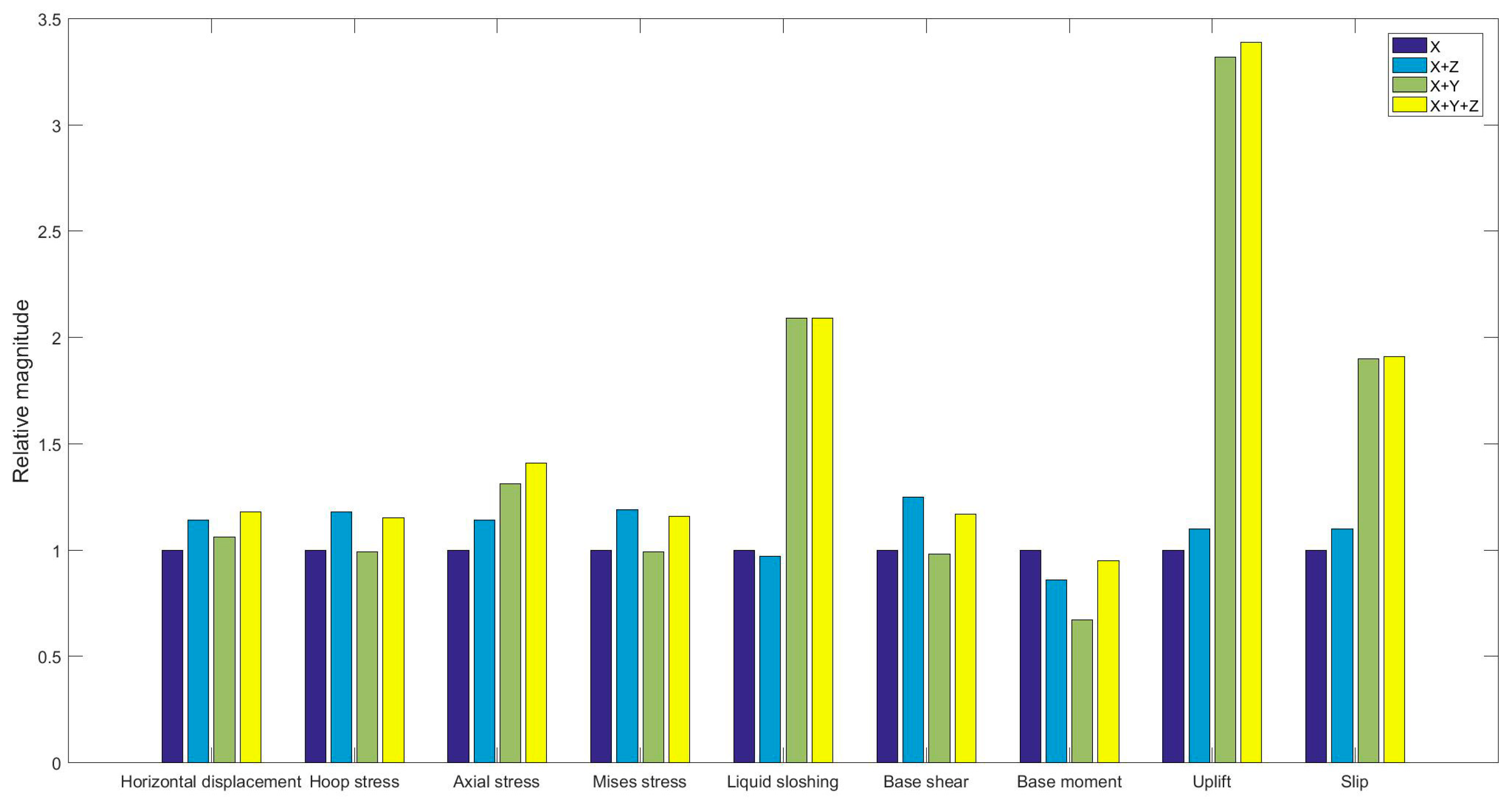
According to the finite element model and the input seismic waves, this section mainly analyzes the deformation of the tank, the distribution of stress along the height of the tank wall, as well as the liquid sloshing, the slippage, and uplift response of the tank bottom. The summation of the maximum seismic response of the tank under the four cases are listed in Table 3. In order to see more intuitively the effect of the input direction on the response of the tank body, set the result of the X excitation as 1, and list the response comparison under the El Centro ground motion, as shown in Figure 6.
4.3.1. Liquid Sloshing
Under the excitation of seismic waves, the liquid surface near the tank wall has a long period of large vertical sloshing. According to Table 3, under the excitation of three selected seismic waves, the liquid sloshing shows great difference. Under the El Centro ground motion, the maximum vertical sloshing height on the liquid surface is 1.078 m when the horizontal X + Y excitation is considered, which is 2.09 times higher than the X excitation; however, it does not reach the contact edge between the tank dome and tank wall. The results obtained by the El Centro ground motion illustrate that the vertical vibration response of the liquid is mainly affected by the horizontal seismic wave excitation, whereas the vertical seismic wave excitation has only a slight effect on the surface liquid sloshing. This is due to the significant difference between the predominant frequency of the vertical seismic wave and liquid sloshing frequency of 8.43 Hz and 0.228 Hz, respectively. Under the other two ground motions, the influence of the direction of the seismic wave on the sloshing of the liquid is not obvious.
4.3.2. Deformation and Stress of the Tank Wall
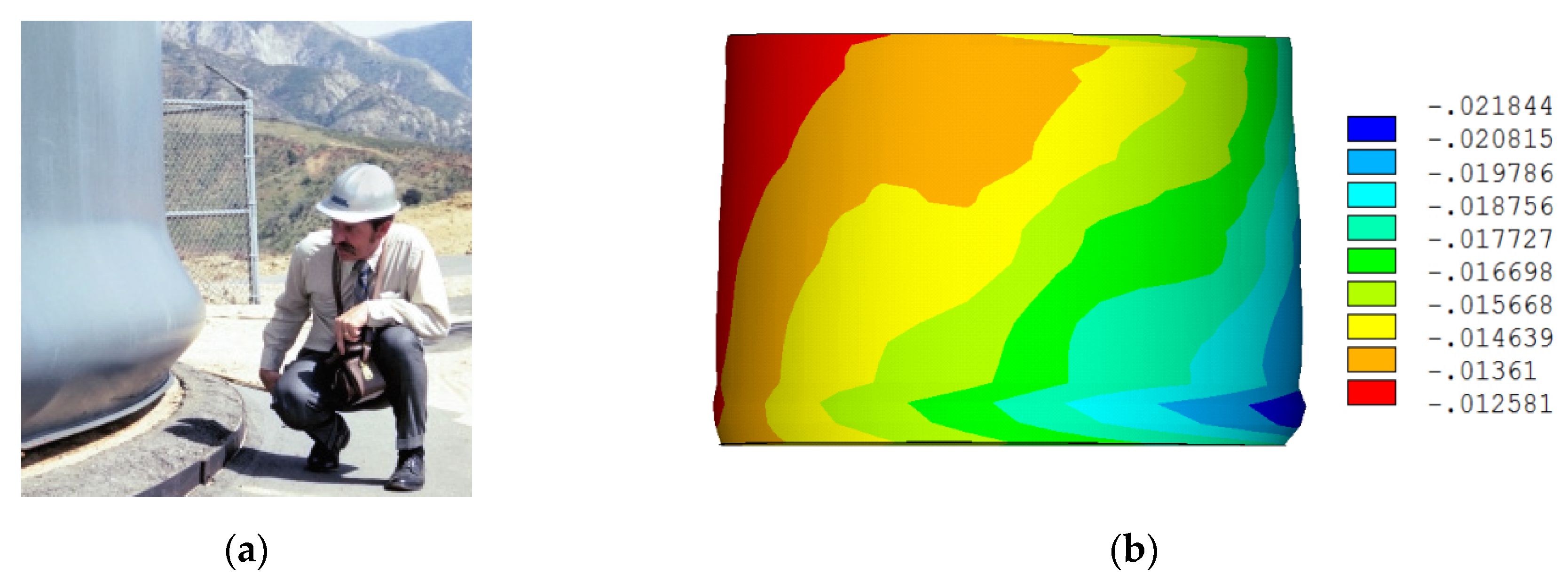
Seismic damage to steel storage tanks may take several forms. Large axial compressive stresses due to the beam-like bending of the tank wall can lead to “elephant-foot” buckling of the wall [19], as shown in Figure 7a. In this study, the “elephant-foot” deformation of the tank wall is also obtained by the numerical simulation method, as shown in Figure 7b. It can be seen that the numerical simulation results in this study are consistent with the actual earthquake damage phenomenon.
The tank is axisymmetric, and the earthquake action is not axisymmetric, so the horizontal displacement along the circumference of the tank body is different at a certain height from the bottom of the tank. In the analysis, for different excitation directions, the locations of the measured nodes are different, as shown in Figure 5. Compared with the unidirectional X excitation, the vertical component will not affect the location of the measurement points, while the horizontal Y component will change the positions of the measurement nodes.
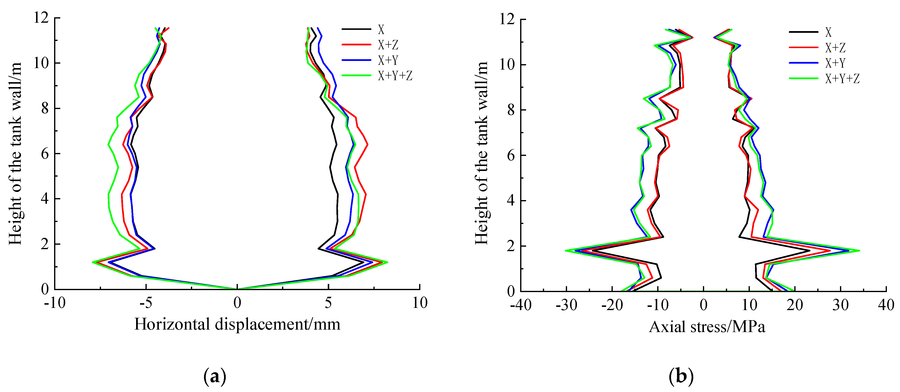
The peak displacements comparison along the tank wall under El Centro ground motion is shown in Figure 8a. The horizontal displacements of the tank wall are nearly symmetrical along the height of the tank. The displacement response of the tank wall is near the bottom of the plate, referred to as the “elephant-foot” deformation, and exhibits the largest displacement. The horizontal deformation of the tank wall suddenly decreases after the deformation of the “elephant-foot” and then continues to increase; that is, 1.8 m away from the bottom of the tank, the tank wall shows discernible relative shrinkage deformation.
As shown in Table 3 and Figure 8a, the “elephant-foot” obtained under the X + Y + Z excitation increased notably compared to that of the X-direction excitation.
The axial compressive stress distribution on the tank wall is shown in Figure 8b. In accordance with the Chinese national standard “Code for design of vertical cylindrical welded steel oil tanks” (GB50341-2014), the stress of the tank wall should be less than the allowable critical axial compressive stress. According to the design specifications, the allowable critical stress of the tank wall under earthquake conditions should be calculated by , where E is the elastic modulus of the tank at the design temperature; t is the effective thickness of the bottom shell; and D is the inner diameter of the tank. The calculated allowable critical stress is 28.77 MPa. It should be noted that the maximum stress at this time has not reached the limit value of the yield stress of the material. From Table 3, the maximum hoop tensile stress is 123.10 MPa, and the maximum Mises stress is 119.97 MPa, and both of them are lower than the yield stress of 235 MPa of the tank.
As shown in Table 3, the most obvious axial compressive stress appears in the tank under the El Centro ground motion. The maximum axial compressive stress of the tank is 31.72 MPa and 34.11 MPa under bi-directional horizontal X + Y excitation and tri-directional X + Y + Z excitation, respectively. Both the results exceed the allowable axial compressive stress of the code, indicating that the deformation of the “elephant-foot” position has reached a buckling failure state. In this case, the tank structure may be in a more dangerous state under the excitation of X + Y + Z seismic waves. It is necessary to consider the influence of both the vertical and bi-directional horizontal components of ground motion.
4.3.3. Uplift and Slip between the Tank Bottom and Foundation
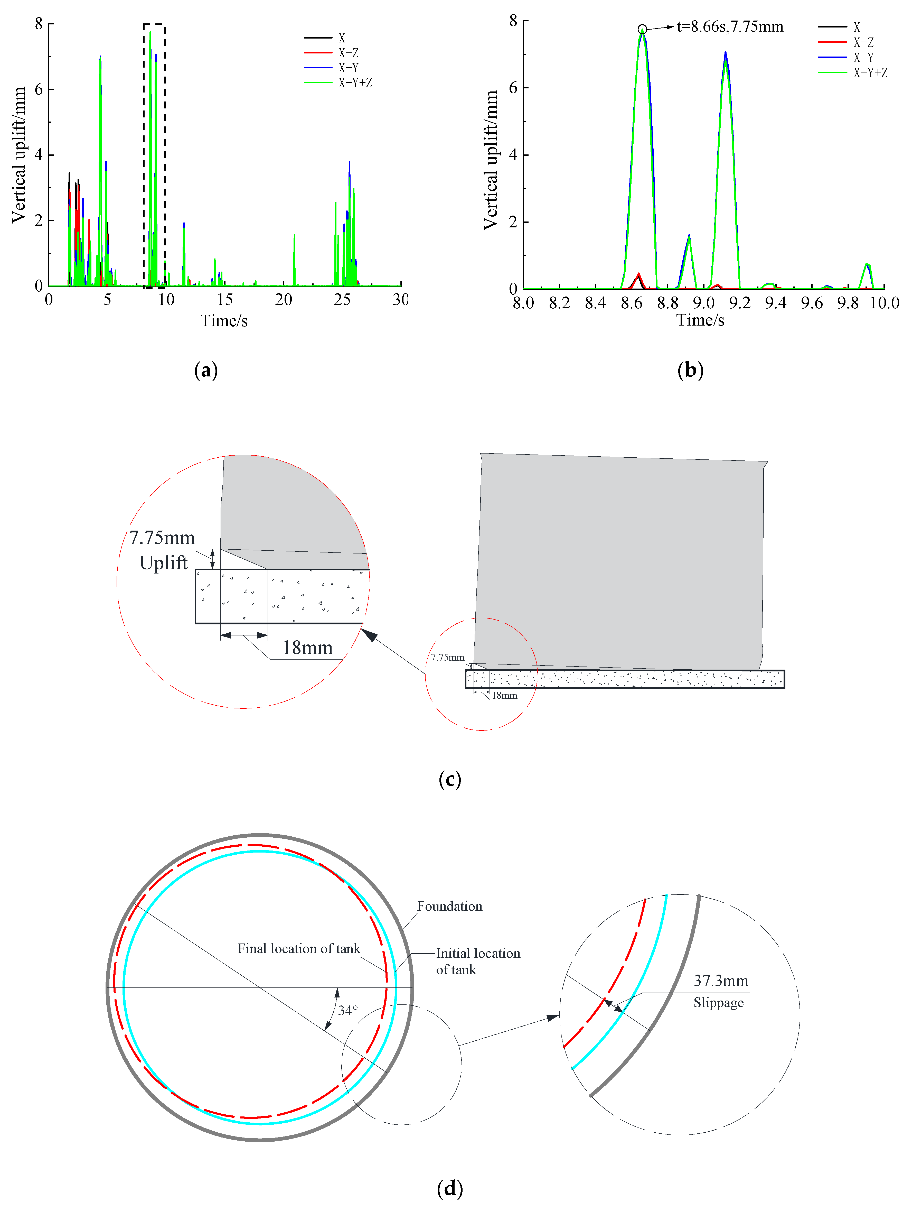
In unanchored or partially anchored tanks, the uplift of the foundation may damage the piping connections which cannot adapt to the vertical displacements, damaging the plate shell structure due to excessive joint stress and leading to uneven settlement of the foundation. In this part, the uplift behavior of the tank bottom is investigated. Table 3 illustrates the maximum uplift of the tank reaches 7.75 mm under X + Y + Z excitation of the El Centro ground motion, which is 1.91 times larger than that of the X-direction excitation. The uplift time-history comparison of the tank bottom under El Centro ground motion is shown in Figure 9a. From the results, the vertical seismic component increases the uplift response of the tank. This phenomenon also occurs when the other two seismic waves are excited.
The maximum slip value is 37.27 mm under X + Y + Z excitation of the El Centro ground motion, which is 3.39 times higher than that of the horizontal X-direction excitation. Figure 9 also gives a comparison of tank bottom’s movement when the earthquake begins and stops under El Centro ground motion with X + Y + Z excitation. Under the excitation of the other two seismic waves, the slip response of the tank is much smaller than that by El Centro ground motion. It can be seen that the characteristics of the seismic wave have an obvious effect on the slip response of the tank. When considering multi-directional ground motions, both the uplift and slip response increases obviously. Especially, excessive tank bottom permanent sliding may cause damage to the tank or even slide out of the foundation. Hence, some restrictions in the tank bottom measures are necessary.
4.3.4. Base Shear and Base Moment of the Tank
From the calculated results in Table 3, the base shear reaches the largest value under X + Z excitation of the El Centro ground motion. It has a significant increase compared with the result by the X excitation. Under the excitation of the other two seismic waves, the base shear also increases obviously with X + Z excitation. Among the three ground motions, the overturning moment is the largest under X excitation of the El Centro ground motion. The vertical seismic component does not increase the overturning moment of the tank except for the Qian’an ground motion. As the vertical excitation component increases the vertical response of the fluid in the tank, the response of the tank caused by the horizontal ground motion is weakened, and the overturning moment of the whole tank is reduced. In general, there is no danger of overturning due to the larger diameter of the tank.
5. Conclusions
Based on the ANSYS software, an unanchored steel storage tank was established as the evaluation object, and three earthquake records were selected to investigate the influence of the multi-directional components of ground motion. The numerical simulation results show that the seismic response of the tank may be underestimated if the tri-directional components are ignored. It is necessary to consider the influence of the multi-directional component in the seismic performance evaluation of a liquid-storage tank.
- The dynamic behavior of the tank structure is highly sensitive to seismic excitation direction. The axial compressive stress of the tank wall reached 34.11 MPa under the application of the tri-directional component of the El-Centro ground motion, and the value exceeds the allowable value in the specification. The results show that there is obvious “elephant-foot” deformation near the bottom of the tank, indicating that buckling failure of the tank wall has occurred.
- Under seismic multi-directional components action, the vertical uplift and horizontal slip behavior between the tank bottom and foundation occur. When the X + Y + Z excitation of the El Centro ground motion is carried on, the uplift and the slip response reaches the maximum, which are 1.91 and 3.39 times higher than those of the X excitation. The base shear of tank will increase after considering the vertical component. However, the overturning moments decrease in different degrees when the tri-directional excitation cases are considered.
- Discussion on the limitation of this work: The case study investigated in this paper is still limited. For example, only an unanchored tank structure is analyzed using three earthquake ground motions, ignoring the soil–structure interaction effect. The seismic performance of the storage tank is closely related to the input seismic wave excitation. The conclusions based on the analysis of just one sample is limited and may lack universal significance. The preliminary conclusion needs to be verified by a sufficient number of earthquake records with a wider spectral range.
Author Contributions
Conceptualization, R.Z. and H.W.; methodology, R.Z.; software, S.C. and K.S.; validation, R.Z.; formal analysis, R.Z.; investigation, Z.Z.; resources, R.Z.; data curation, S.C.; writing—original draft preparation, R.Z.; writing—review and editing, R.Z.; supervision, R.Z. All authors have read and agreed to the published version of the manuscript.
Funding
This research was funded by National Natural Science Foundation of China (Grant No. 51608462), Shandong Provincial Natural Science Foundation (Grant No. ZR2019MEE099), and the Fundamental Research Funds for the Central Universities (Grant No. 18CX02081A).
Conflicts of Interest
The authors declare no conflict of interest.
References
- Curadelli, O. Equivalent linear stochastic seismic analysis of cylindrical base-isolated liquid storage tanks. J. Constr. Steel Res. 2013, 83, 166–176. [Google Scholar] [CrossRef]
- Manos, G.C.; Clough, R.W. Tank damage during the May 1983 Coalinga earthquake. Earthq. Eng. Struct. Dyn. 1985, 13, 449–466. [Google Scholar] [CrossRef]
- Sezen, H.; Livaoğlu, R.; Dogangun, A. Dynamic analysis and seismic performance evaluation of above-ground liquid-containing tanks. Eng. Struct. 2008, 30, 794–803. [Google Scholar] [CrossRef]
- Tian, L.; Li, H.-N. Seismic response analysis of transmission tower-line system under multi-component ground motion excitations. J. Civ. Environ. Eng. 2013, 35, 86–95. [Google Scholar]
- Zhang, J.; Li, H.-N.; Wang, L.-C. The research of multi-dimensional seismic responses of large span asymmetric spatial structure. Earthq. Eng. Eng. Dyn. 2015, 35, 8–16. [Google Scholar]
- Haroun, M.A.; Tayel, M.A. Response of tanks to vertical seismic excitations. Earthq. Eng. Struct. Dyn. 1985, 13, 583–595. [Google Scholar] [CrossRef]
- Ghaemmaghami, A.R.; Kianoush, R. Effect of wall flexibility on dynamic response of concrete rectangular liquid storage tanks under horizontal and vertical ground motions. J. Struct. Eng. 2010, 136, 441–451. [Google Scholar] [CrossRef] [Green Version]
- Sobhan, M.; Rofooei, F.R.; Attari, N.K.A. Buckling behavior of the anchored steel tanks under horizontal and vertical ground motions using static pushover and incremental dynamic analyses. Thin Walled Struct. 2017, 112, 173–183. [Google Scholar] [CrossRef]
- Haroun, M.A.; Temraz, M.K. Effects of soil-structure interaction on seismic response of elevated tanks. Soil Dyn. Earthq. Eng. 1992, 11, 73–86. [Google Scholar] [CrossRef]
- Haroun, M.A.; Abou-Izzeddine, W. Parametric study of seismic soil-tank interaction. I: Horizontal excitation. J. Struct. Eng. 1992, 118, 783–797. [Google Scholar] [CrossRef]
- Haroun, M.A.; Abou-Izzeddine, W. Parametric study of seismic soil-tank interaction. II: Vertical excitation. J. Struct. Eng. 1992, 118, 798–811. [Google Scholar] [CrossRef]
- Bakalis, K.; Kazantzi, A.K.; Vamvatsikos, D.; Fragiadakis, M. Seismic performance evaluation of liquid storage tanks using nonlinear static procedures. J. Press. Vessel. Technol. 2018, 141, 010902. [Google Scholar] [CrossRef]
- Colombo, J.; Almazán, J. Simplified 3D model for the uplift analysis of liquid storage tanks. Eng. Struct. 2019, 196, 109278. [Google Scholar] [CrossRef]
- Miladi, S.; Razzaghi, M.S. Failure analysis of an un-anchored steel oil tank damaged during the Silakhor earthquake of 2006 in Iran. Eng. Fail. Anal. 2019, 96, 31–43. [Google Scholar] [CrossRef]
- Livaoglu, R.; Dogangun, A.; Doǧangün, A. Effect of foundation embedment on seismic behavior of elevated tanks considering fluid–structure-soil interaction. Soil Dyn. Earthq. Eng. 2007, 27, 855–863. [Google Scholar] [CrossRef]
- ANSYS Incorporated. Programmer’s Manual for ANSYS; Release 11.0. 2007; ANSYS: Pittsburgh, PA, USA, 2007. [Google Scholar]
- Zhang, R.-L.; Cheng, X.-D.; Guan, Y.-H.; Tarasenko, A.A. Seismic response analysis of an unanchored vertical vaulted-type tank. Earthq. Struct. 2017, 13, 67–77. [Google Scholar]
- National Standards of the People’s Republic of China. In Code for Design of Vertical Cylindrical Welded Steel Oil Tanks; China Planning Press: Beijing, China, 2014.
- Malhotra, P.K.; Wenk, T.; Wieland, M. Simple procedure for seismic analysis of liquid-storage tanks. Struct. Eng. Int. 2000, 10, 197–201. [Google Scholar] [CrossRef] [Green Version]
Figure 1.
Finite element model of the fluid–tank–foundation system and a schematic diagram of the fluid–structure coupling.
Figure 1.
Finite element model of the fluid–tank–foundation system and a schematic diagram of the fluid–structure coupling.

Figure 2.
Acceleration time-history curves of the El Centro ground motion: (a) X-direction; (b) Y-direction; (c) Z-direction.
Figure 2.
Acceleration time-history curves of the El Centro ground motion: (a) X-direction; (b) Y-direction; (c) Z-direction.

Figure 3.
Fourier spectra of the El Centro ground motion: (a) X-direction; (b) Y-direction; (c) Z-direction.
Figure 3.
Fourier spectra of the El Centro ground motion: (a) X-direction; (b) Y-direction; (c) Z-direction.

Figure 4.
A schematic diagram of the four calculation conditions (the dotted line on the axis indicates that there is no excitation in this direction).
Figure 4.
A schematic diagram of the four calculation conditions (the dotted line on the axis indicates that there is no excitation in this direction).

Figure 5.
Selected feature points for analysis (plan).

Figure 6.
Comparison of the peak normalization of the seismic response of the tank under El Centro ground motion.
Figure 6.
Comparison of the peak normalization of the seismic response of the tank under El Centro ground motion.

Figure 7.
“Elephant-foot” buckling of the tank: (a) “Elephant-foot” buckling of a real tank [19]; (b) “Elephant-foot“ buckling deformation of the tank in this study (under El Centro ground motion, t = 2.74 s, X + Y + Z excitation).
Figure 7.
“Elephant-foot” buckling of the tank: (a) “Elephant-foot” buckling of a real tank [19]; (b) “Elephant-foot“ buckling deformation of the tank in this study (under El Centro ground motion, t = 2.74 s, X + Y + Z excitation).

Figure 8.
Distribution of the seismic response results along the height of the tank wall under El Centro ground motion: (a) horizontal displacement; (b) axial stress.
Figure 8.
Distribution of the seismic response results along the height of the tank wall under El Centro ground motion: (a) horizontal displacement; (b) axial stress.

Figure 9.
Uplift and slip behavior of the tank bottom under El Centro ground motion: (a) The whole time-history curve comparison of tank bottom uplift; (b) time-history curve of the uplift amount during t = 8.0 s to t = 10.0 s; (c) uplift behavior of the tank (t = 8.66 s, under the X + Y + Z excitation, after a certain amplification); (d) change of tank position before and after the earthquake (under the X + Y + Z excitation, top view).


Table 1.
Comparison of the natural frequency by a numerical solution and other literature.
| Natural Frequency | Numerical Results/Hz | Theoretical Results | Code Results | ||
|---|---|---|---|---|---|
| Value/Hz | Error/% | Value/Hz | Error/% | ||
| Fluid Convective Frequency, fw | 0.228 | 0.216 | 5.56 | 0.216 | 5.56 |
| Fluid–tank coupling impulsive frequency, fc | 7.046 | 7.084 | 0.54 | 7.188 | 1.98 |
Table 2.
Characteristics of the earthquake ground motions.
| Earthquake | Date | Recording Station | X-Direction Component PGA/g | Y-Direction Component PGA/g | Z-Direction Component PGA/g |
|---|---|---|---|---|---|
| Imperial Valley, California | 19 May 1940 | El Centro | 0.281 | 0.211 | 0.178 |
| Tangshan, Hebei | 9 August 1976 | Qian’an Lanhe Bridge | 0.162 | 0.153 | 0.081 |
| Northridge, California | 17 January 1994 | CDMG Station 23595 | 0.072 | 0.060 | 0.036 |
Table 3.
Comparison of the peak response quantities under the four cases.
| Earthquake Excitation | Peak Response Quantities | X | X + Z | X + Y | X + Y + Z |
|---|---|---|---|---|---|
| Imperial Valley, 1940 | Horizontal displacement/mm | 6.97 | 7.94 | 7.41 | 8.23 |
| Hoop stress/MPa | 103.92 | 123.10 | 102.85 | 119.95 | |
| Axial stress/MPa | 24.26 | 27.66 | 31.72 | 34.11 | |
| Mises stress/MPa | 100.74 | 119.97 | 99.58 | 116.39 | |
| Sloshing/m | 0.515 | 0.501 | 1.078 | 1.076 | |
| Base shear/kN | 4766.66 | 5966.91 | 4685.81 | 5583.32 | |
| Base moment/(103 kN m) | 35.75 | 30.65 | 23.92 | 33.80 | |
| Slip/mm | 11.00 | 12.06 | 36.51 | 37.27 | |
| Uplift/mm | 4.05 | 4.45 | 7.69 | 7.75 | |
| Tangshan, 1976 | Horizontal displacement/mm | 6.94 | 7.35 | 7.19 | 7.37 |
| Hoop stress/MPa | 103.22 | 115.44 | 104.68 | 115.71 | |
| Axial stress/MPa | 23.04 | 23.79 | 24.38 | 25.18 | |
| Mises stress/MPa | 100.47 | 109.57 | 101.85 | 110.13 | |
| Sloshing/m | 0.171 | 0.174 | 0.175 | 0.177 | |
| Base shear/kN | 4739.40 | 5079.25 | 4699.27 | 5100.14 | |
| Base moment/(103 kN m) | 22.11 | 23.34 | 22.51 | 22.77 | |
| Slip/mm | 3.62 | 4.79 | 4.88 | 5.66 | |
| Uplift/mm | 3.23 | 3.63 | 3.42 | 4.00 | |
| Northridge, 1994 | Horizontal displacement/mm | 7.01 | 7.14 | 6.92 | 7.29 |
| Hoop stress/MPa | 102.07 | 115.51 | 100.98 | 115.03 | |
| Axial stress/MPa | 22.91 | 22.04 | 22.16 | 22.29 | |
| Mises stress/MPa | 98.99 | 111.77 | 99.50 | 110.65 | |
| Sloshing/m | 0.0335 | 0.0372 | 0.0338 | 0.0393 | |
| Base shear/kN | 4709.30 | 4822.63 | 4034.51 | 4184.47 | |
| Base moment/(103 kN m) | 22.08 | 21.89 | 20.65 | 21.36 | |
| Slip/mm | 3.39 | 3.41 | 6.74 | 6.68 | |
| Uplift/mm | 2.73 | 2.85 | 4.09 | 4.37 |
© 2020 by the authors. Licensee MDPI, Basel, Switzerland. This article is an open access article distributed under the terms and conditions of the Creative Commons Attribution (CC BY) license (http://creativecommons.org/licenses/by/4.0/).
Share and Cite
MDPI and ACS Style
Zhang, R.; Chu, S.; Sun, K.; Zhang, Z.; Wang, H. Effect of the Directional Components of Earthquakes on the Seismic Behavior of an Unanchored Steel Tank. Appl. Sci. 2020, 10, 5489. https://doi.org/10.3390/app10165489
AMA Style
Zhang R, Chu S, Sun K, Zhang Z, Wang H. Effect of the Directional Components of Earthquakes on the Seismic Behavior of an Unanchored Steel Tank. Applied Sciences. 2020; 10(16):5489. https://doi.org/10.3390/app10165489
Chicago/Turabian StyleZhang, Rulin, Shili Chu, Kailai Sun, Zhongtao Zhang, and Huaifeng Wang. 2020. "Effect of the Directional Components of Earthquakes on the Seismic Behavior of an Unanchored Steel Tank" Applied Sciences 10, no. 16: 5489. https://doi.org/10.3390/app10165489
Note that from the first issue of 2016, this journal uses article numbers instead of page numbers. See further details here.