Free Vibrations of Tapered Horseshoe Circular Arch with Constant Volume

1
Department of Civil and Environmental Engineering, Wonkwang University, 460 Iksan-daero, Iksan-si, Jeollabuk-do 54538, Korea
2
Department of Civil and Environmental Engineering, Jeonnam State University, 152 Jookrokwon-ro, Damyang-eup, Jeollanam-do 57337, Korea
3
School of Architecture, Civil and Landscape Engineering, Donggang University, 50 Dongmoon-daero, Buk-gu, Kwangju-si 61200, Korea
*
Author to whom correspondence should be addressed.
Appl. Sci. 2020, 10(16), 5431; https://doi.org/10.3390/app10165431
Submission received: 3 July 2020
/
Revised: 2 August 2020
/
Accepted: 3 August 2020
/
Published: 6 August 2020
(This article belongs to the Special Issue Vibration and Sound Control by Acoustic Meta Structures)
Abstract
:This paper presents free vibrations of the tapered horseshoe circular arch with a constant volume. The volume of the arch is constant, and the cross-sectional shape of the arch is square and circular. The taper function of the arch is a quadratic function. Differential equations with the boundary conditions that govern the free vibration of such arches are derived and numerically solved to calculate natural frequencies and mode shapes. The natural frequencies of this study agree well with those of the finite element ADINA. Parametric studies of the geometrical and cross-sectional properties of the arch on frequencies and mode shapes are performed and discussed.
1. Introduction
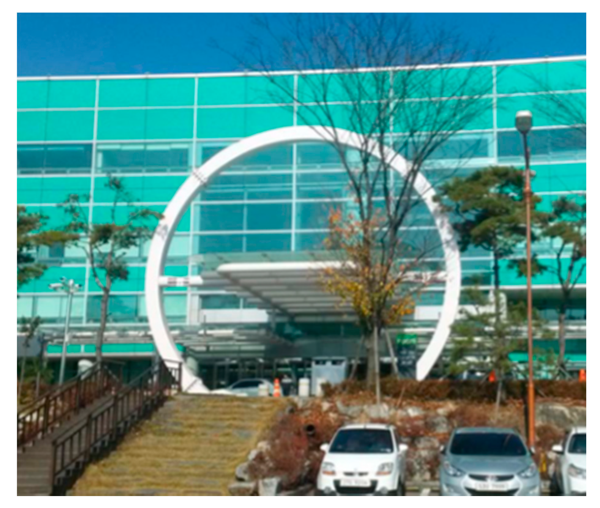
Arches are frequently erected in many engineering fields because of their beautiful appearance and excellent structural function. The horseshoe arch is an arch shape in which the length of the longitudinal secant line increases from the peak of the arch, reaches its maximum value on the horizontal axis, and decreases to the span length of the lower opening [1]. In particular, the horseshoe arch is widely used as a framed structure in the fields of civil, architecture, aerospace, and ship-building engineering because it can utilize a wide range of working space under the arch member [2]. The arch can be graded in cross-section in the axial direction; meanwhile, in order to meet the aesthetic and economic cost (or minimum weight) demands of the arch, the non-prismatic arch may be employed in the form of tapered, piecewise, and continuous segmented member [3]. Figure 1 shows an example of a horseshoe arch erected as an entrance portal that goes well with a modern building.
Exciting the dynamic load acting on the structure creates an element that weakens the structure function due to the resonance phenomenon of the free vibration characteristics. Therefore, free vibration is one of the important research tasks of structural analysis, from the design stage of the structure to monitoring the soundness of the structure in public use [4].
Over the last several decades, many researchers, such as Timoshenko [5], Henrych [6], and Chidamparam and Leissa [7], have published free vibration behavior, including arch structures. Considering the research trends of the free vibration of the arch, it is as follows. The arch’s free vibration solutions can be divided into the closed and approximate. The closed form solution [8,9] is very complicated, so there are few research results. The approximate form solution is obtained from the numerical method that calculates mode shapes by numerically integrating the governing differential equation, the eigenvalues of natural frequencies by the determinant search method, and most of research works included here [1,2,10,11,12,13,14,15].
In the design of the arched structure, it is most important to choose the suitable arch shape, so various linear shapes such as circular [1,8,9,12,13,15], parabolic [10], elliptical [2,11], catenary [16], and elastica [17] have been studied. In addition, research topics include the variable cross-section [8,13,14], material properties [9,12,15], multi-span arch [18], secondary effects on frequencies [19], and frequency optimization [20]. As mentioned above, the free vibration studies of arches are still being actively studied, from the linear shape to frequency optimization of the arch.
In the open literature, only two works [1,2] that directly dealt with the problem of free vibration of a horseshoe arch are available, where the circular and elliptic arches with uniform cross-sections, but not tapered, are covered. High-rise arches, especially horseshoe arches, are vulnerable to stability, so tapered members should be used properly to improve the stiffness of the arch. In this regard, this paper focuses on the free vibration of a tapered horseshoe arch.
In this study, differential equations governing in-plane free vibrations of tapered horseshoe circular arches are derived and numerically solved to compute natural frequencies with their mode shapes. In particular, the effects of a cross-sectional shape, taper ratio, rotatory inertia couple, and volume ratio are included, in combination or separation, in the governing differential equations, implying the novelty of this study. Parametric studies affecting natural frequencies and mode shapes have been conducted and discussed extensively.
2. Problem Formulation
2.1. Geometry of Arch
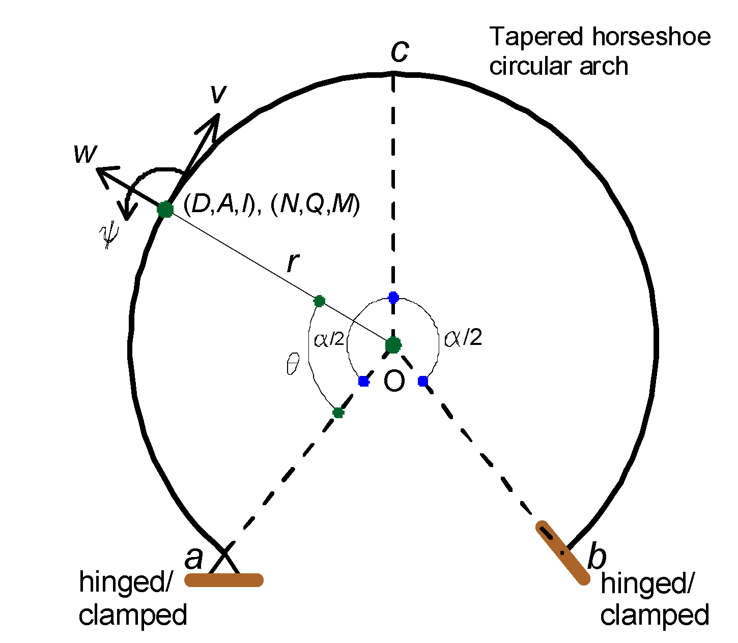
Figure 2 shows the geometry of a horseshoe circular arch with radius and the opening angle . The arch axis is defined by the angular coordinates where the center of the circle is O. Both ends and of the arch are supported by the hinged or clamped end constraint. The arch member is tapered, and its depth, area, and second moment of plane area at are denoted by () respectively, which are defined in Figure 3. When the arch vibrates, each of the radial deformation , tangential deformation , and angular rotation occurs in the cross-section at . In this study, the free vibration assumes a harmonic motion in which each dynamic coordinate is proportional to . For example, the dynamic radial deformation is expressed as , where is the radial amplitude (deformation), is the angular frequency, is the mode number, and is the time. As a result, the dynamic axial force , shear force and bending moment occur in the cross-section of the arch due to deformations .
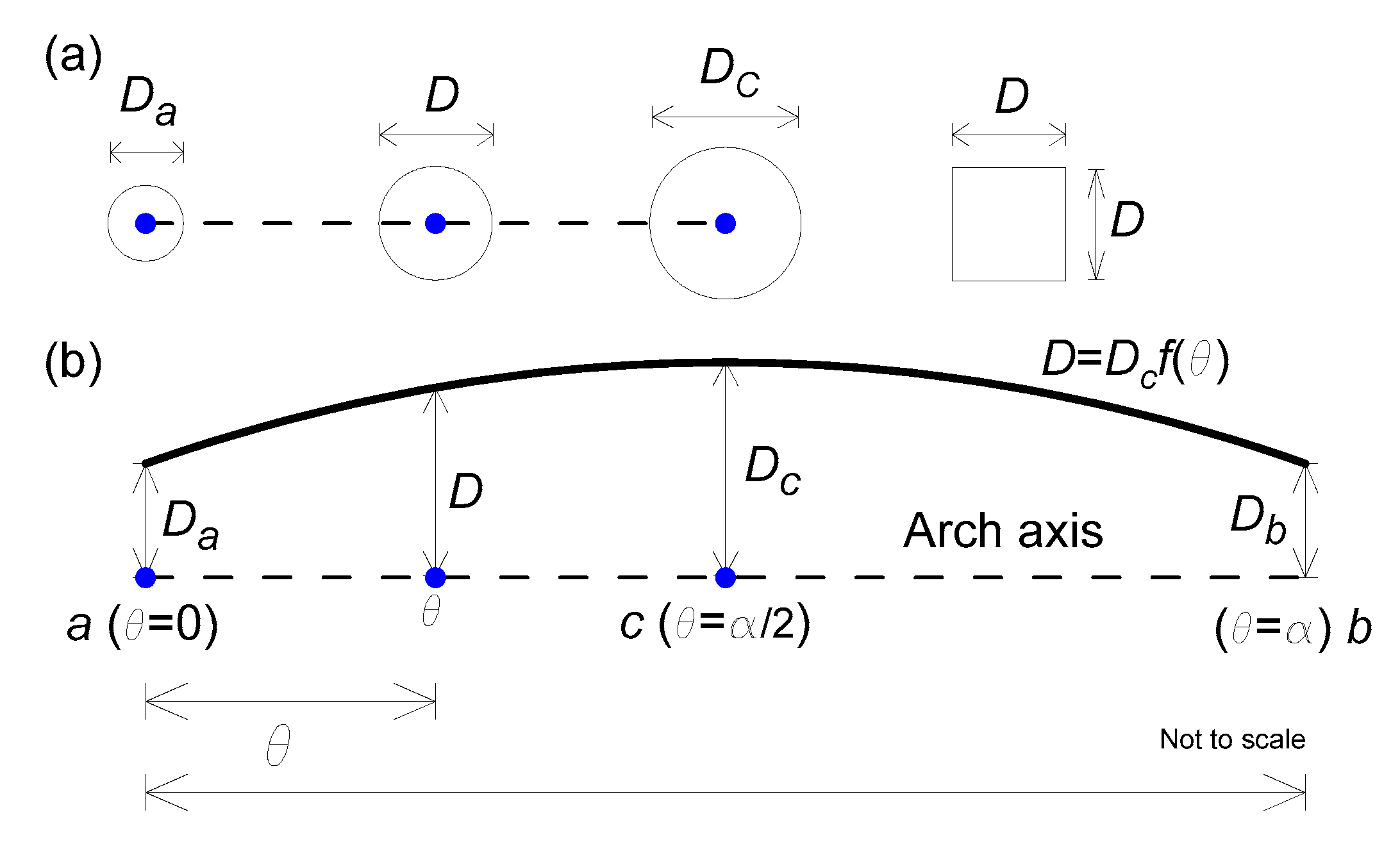
Shown in Figure 3 is the axially functionally tapered arch, from which the cross-sectional properties of and can be established. The cross-sectional shape is square or circular with the varying arch depth at as shown in Figure 3a. Here, is the height for the square and the diameter for the circular cross-sections, respectively. In Figure 3b, the tapering fashion is represented by a function of a single variable . At the support and , is depicted by and at the mid-arc , is depicted by . The taper function of is practically used in terms of the linear, polynomial and periodic function [3,19,20,21]. In this study, the tapering function is chosen as a quadratic function with respect to .
To determine the quadratic function , the following taper ratio is defined:
Using Equation (1), the quadratic function in terms of a univariate variable can be expressed as follows.
where the equation is a convex taper when , a uniform prismatic when and a concave taper when , (see Figure 3b).
Using Equation (1), and at are expressed by the definition:
where, for square and for cross-section.
The volume of the arch is obtained as follows.
in which it is particularly noted that is constant in free vibration problems considered in this study.
The above Equation (5) is rearranged against the depth at the mid-arc, or
Using Equation (6) together with Equations (3) and (4) yields
2.2. Governing Differential Equations
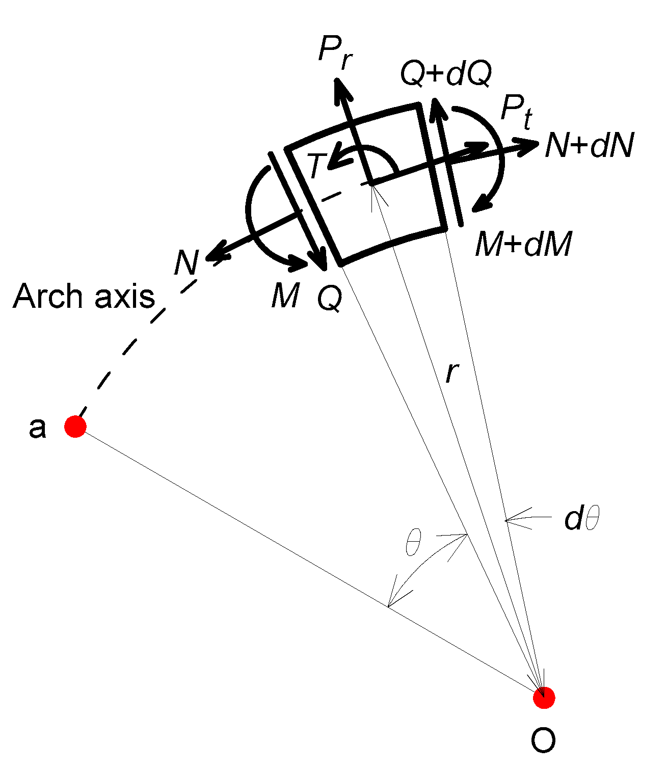
Figure 4 is a free body diagram of an arch element under a free vibration state. The stress resultants due to deformations act in the cross-section of this element, and the inertia forces occur on this element having mass due to accelerations.
From the free body diagram, equilibrium equations of , , are obtained as
where and of the differential operators.
The equations of related to the deformations consider the axial deformation due to , those are given in following equations [22].
First derivatives of in Equations (12) and (13) are obtained as
Substituting Equations (17) and (19) into Equation (11) and arranging against gives Equation (20), and then the first derivative is obtained as Equation (21).
The following non-dimensional parameters are defined to derive differential equations in the non-dimensional forms.
where are the radial and tangential dimensionless deformations, is the volume ratio and is the frequency parameter.
By substituting Equations (12), (15) and (21) into Equation (10) and applying dimensionless Equations (22)–(25), the differential Equation (26) can be obtained. Similarly, by substituting Equations (16), (18) and (20) into Equation (9), the differential Equation (24) can be derived.
where derivatives of in the above two equations are obtained from Equation (2), or
In Equations (26) and (27), the term in is due to the rotatory inertia couple . If differential equations ignore , the term in is simply deleted.
2.3. Boundary Conditions
In order to solve differential equations as the initial and boundary value problems, the boundary conditions of the hinged and clamped end constraints at both ends of the arch and are necessary. The deformations and the bending moment expressed by Equation (13) at the hinged end or are zero. By applying Equations (23) and (24) to the boundary conditions, the dimensionless boundary conditions of the hinged end can be obtained, or
The deformations ( and the angular rotation expressed by Equation (14) at the clamped end or are zero. By applying Equations (22) and (23) to the boundary conditions, the dimensionless boundary conditions of the clamped end can be obtained, or
3. Solution Methods and Validation
The input parameters of the differential equations, Equations (26) and (27), are as follows: end constraint (hinged-hinged, hinged-clamped/clamped-hinged and clamped-clamped); opening angle ; taper ratio ; and volume ratio . The boundary conditions, Equations (29)–(34), were subjected to the differential equations according to the given end condition, and the frequency parameter with the mode shape were calculated. In order to calculate , the differential equations were numerically integrated by the Runge–Kutta method [24], which is a direct integration method, and was calculated by the determinant search method enhanced by the Regula–Falsi method [24], which is a numerical solution method of the nonlinear equation. These kinds of numerical methods have proven useful in several studies [2,15,20], so detailed descriptions are omitted here.
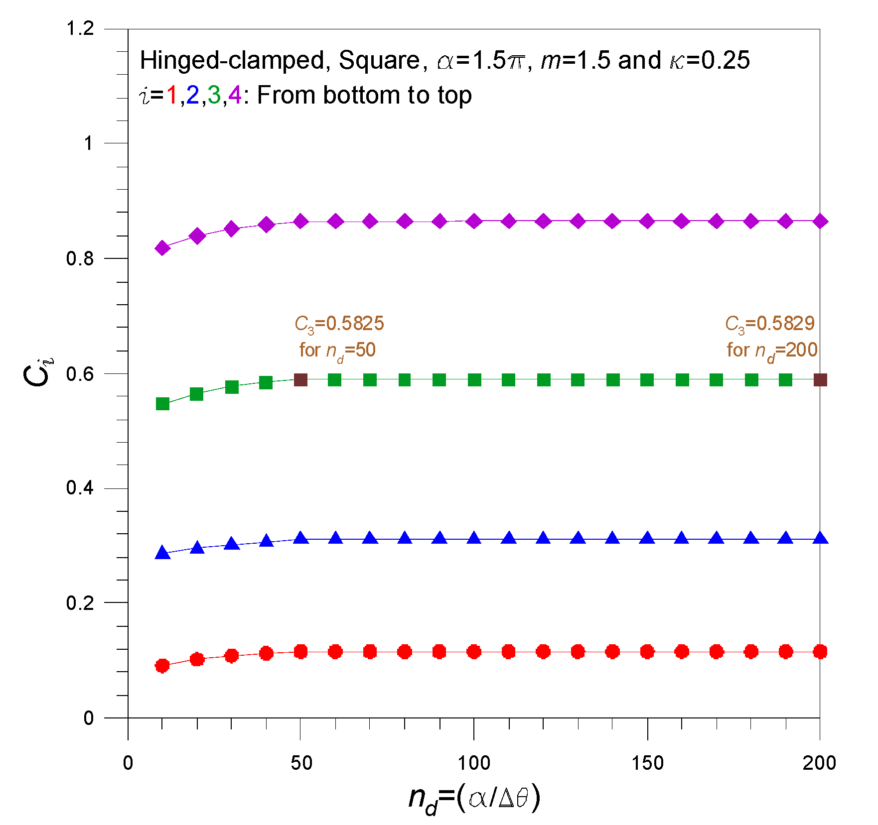
Before the numerical analysis, convergence analysis was performed to ensure the accuracy of the numerical solutions. Since the accuracy of numerical solution is influenced by step size in the Runge–Kutta method [24], convergence analysis of was performed for the number of partitions of the arch axis shown below.
The input arch parameters used for convergence analysis are hinged-clamped, square cross-section, , and . The convergence analysis for the lowest four were conducted and the results are shown in Figure 5. The convergence of with increasing is very stable, and the reliability of the numerical solutions of this study can be confirmed. The solutions converged from to within the order of three significant figures (see ). Then, was used to calculate in this study.
To verify the numerical analysis, Table 1 compares the angular frequency in rad/s of this study and the finite element solution ADINA. The radius of the arch is 1 m and the arch material is steel with The depth and with the input dimensionless parameters are listed in the table. As shown in this table, of the two results is very close, implying that the feasibility of this study could be verified with a maximum error of less than 2.70% and an average error of 1.20%.
4. Numerical Examples and Discussions
Table 2 shows the effect of the rotatory inertia couple on the frequency parameter . The input arch parameters are square cross-section, and Considering the effect of , decreases compared to the case where is not considered. When considering in the dynamic analysis of a structure, the natural frequency decreases since the deformation increases under the same energy. The effect of on is greater in the higher order mode than in the lower order mode. For example, in the clamped-clamped arch, under the same , the reduction rate of is 0.19% , but the larger reduction rate of is 0.57% . The effect of is greater for larger volume ratio than for smaller volume ratio. In the above clamped-clamped arch, under the same , the reduction rate of is 1.43% , which is larger than the reduction rate 0.57% of . Therefore, when a high frequency dynamic load is applied to a tapered horseshoe arch with a large volume ratio, the influence of should be considered to accurately analyze the dynamic behavior.
Table 3 shows the effect of the cross-sectional shape on frequency parameter . The input arch parameters are , with the rotatory inertia couple. The of the square cross-section is larger than those of the circular cross-section, regardless of the end condition and mode number. Its effect is larger in lower mode than in higher mode. For example, in clamped-clamped end conditions, the effect is 2.28% (0.16130/0.15771 = 1.0228) for the first mode, while the effect is 0.081% (0.87560/0.86855 = 1.0081) for the fourth mode.
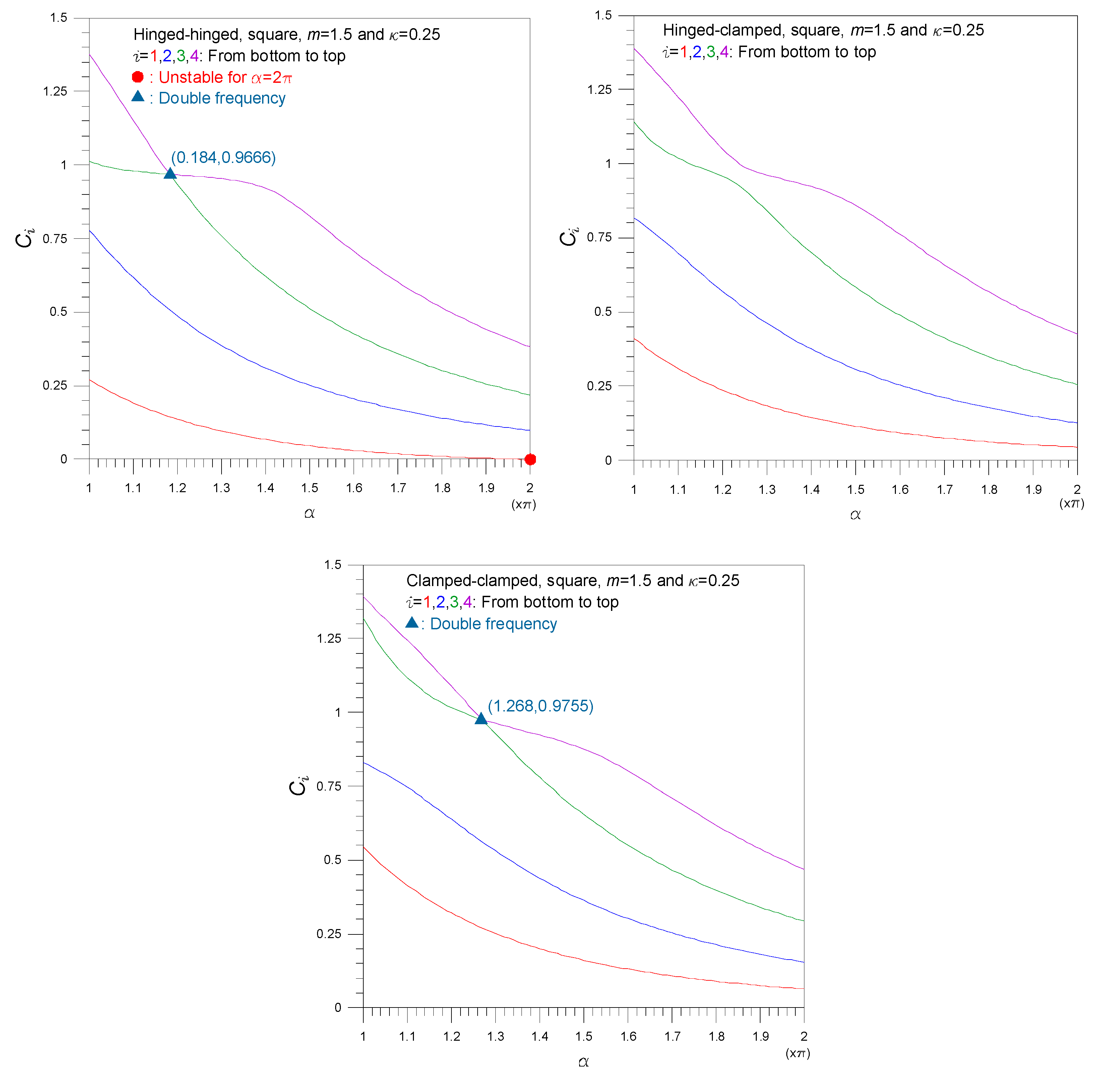
In the following discussion, the effect of was included in numerical examples. Figure 6 shows the natural frequency curve of the frequency parameter according to the change in the opening angle . The input arch parameters are square cross-section, and . As increases, decreases. As increases, the span length of the arch decreases, while the height increases and structural stiffness of the arch decreases, resulting in a decrease in . In the hinged-hinged arch, when the arch becomes a complete circle of marked with ●, vanishes, i.e., and the arch becomes unstable. The hinged-hinged arch with means that the whole structure becomes ‘unstructured’ because it cannot resist the lateral load. This is consistent with the results of the free vibrations of elastica arch [17]. Meanwhile, the hinged-clamped and clamped-clamped arches with can maintain a stable state because it can resist the lateral load at the clamped end. For the hinged-hinged and clamped-clamped arch, there is a double frequency in the coordinates marked with . It is a well-known phenomenon that the mode shape can be changed from symmetric to anti-symmetric or vice versa [19,20,21]. On the other hand, in the case of the hinged-clamped arch, there is no double frequency because the end condition is asymmetric. This is also a well-known fact, a so-called veering phenomenon, that in the case of an asymmetric arch, the two frequency curves are merely approached, but not met as shown in this figure [25].
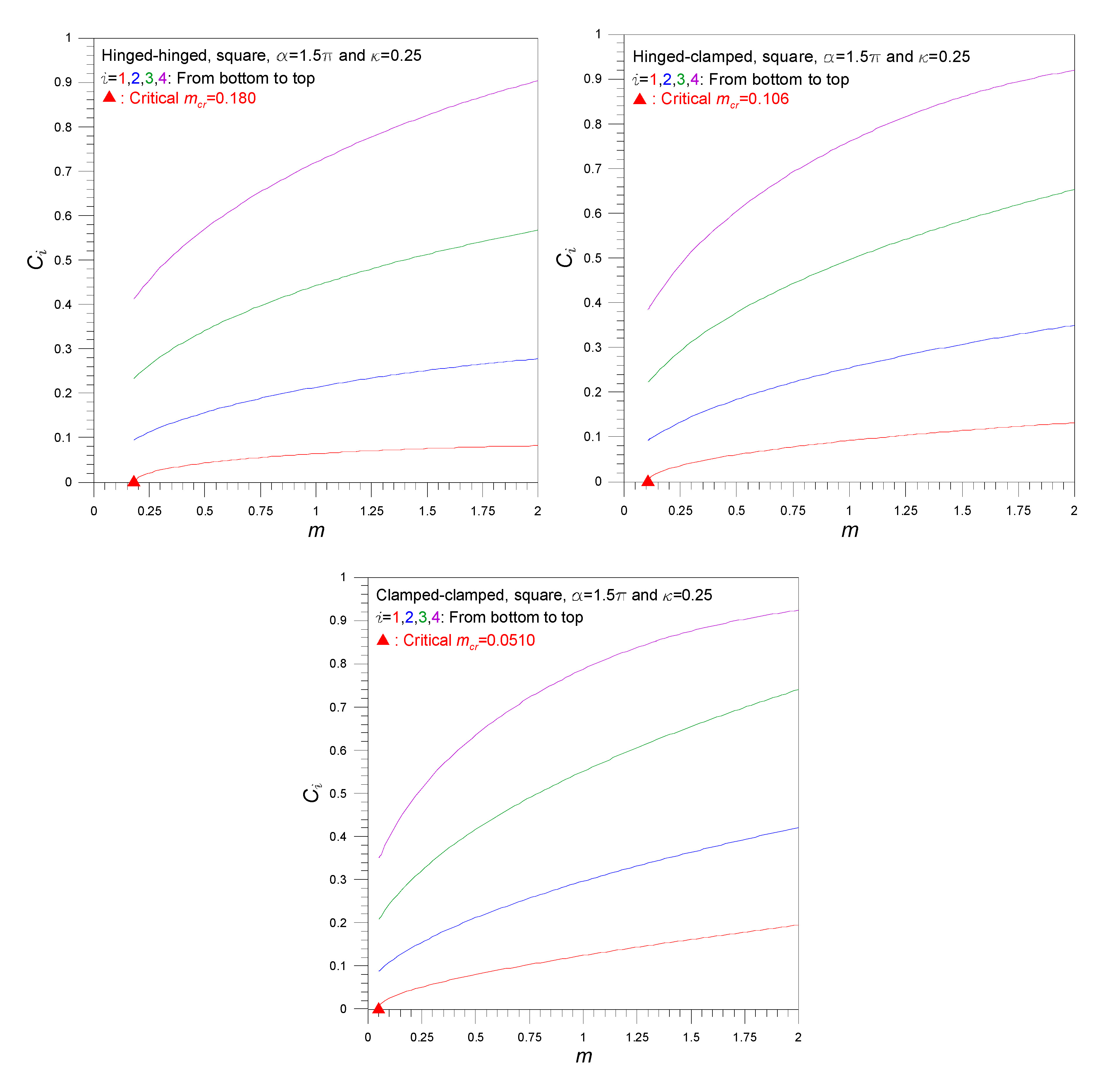
Figure 7 shows the natural frequency curve of the frequency parameter according to the change in the taper ratio . The input arch parameters are square cross-section, and . As increases, increases. If is larger, the tapered arch is more rigid at the two support ends comparing the mid-arc. Thus, when constructing a horseshoe arch, it is necessary to place more rigidity on the two supporting ends and than the mid-arc , and a structurally more rigid arch can be realized. As shown in this figure, if is less than the critical taper ratio marked with , the lowest frequency parameter vanishes and the arch become unstable. For example, the hinged-hinged arch with less than cannot resist from the dynamic load and becomes unstable.
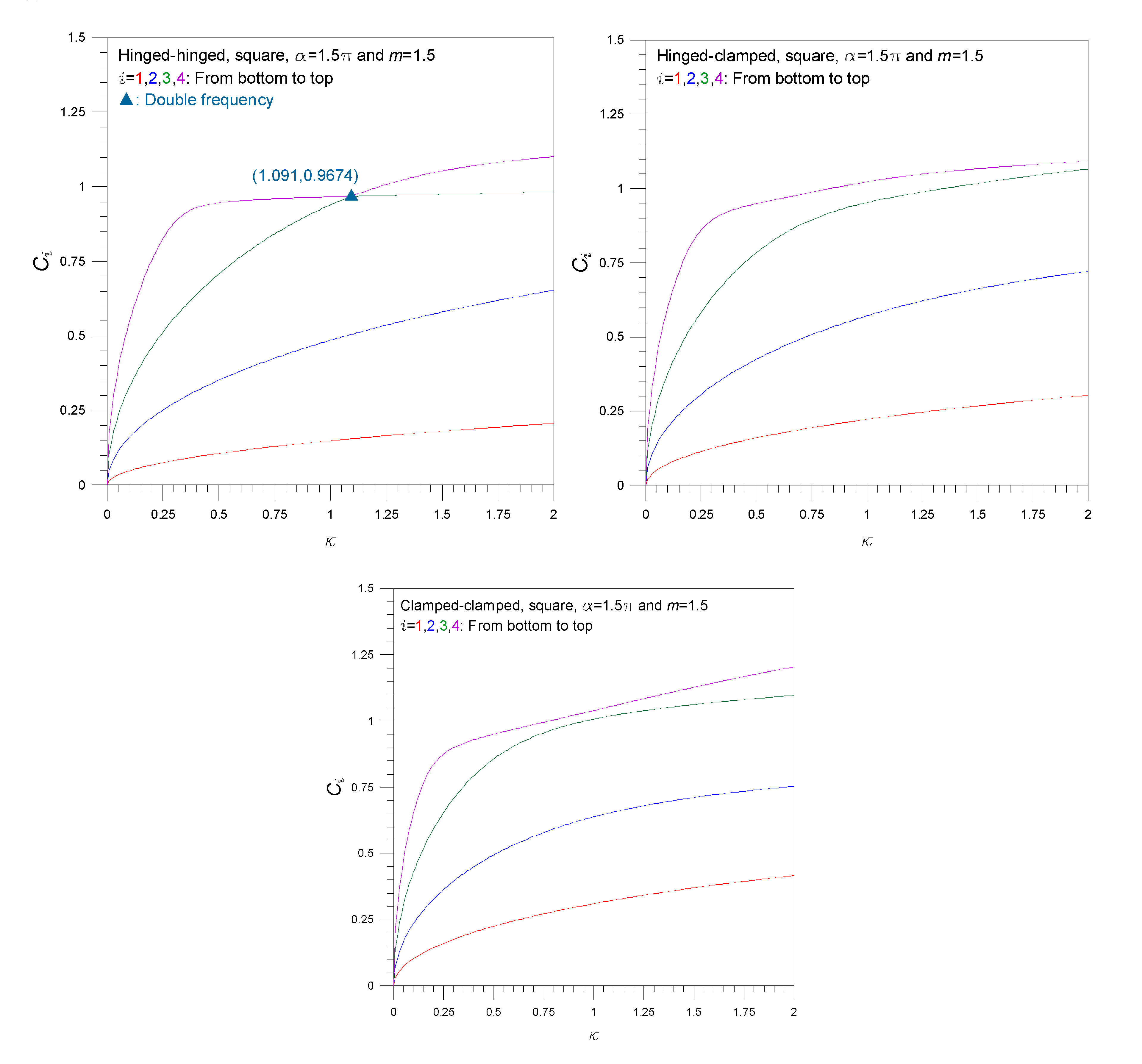
Figure 8 shows the natural frequency curve of the frequency parameter according to the change in the volume ratio . The input arch parameters are square cross-section, and . As increases, increases. As increases, the structural stiffness of the arch decreases, so decreases. In the small region of , the spacing between natural frequency curves is narrow, implying that the effect of on has a greater effect on smaller . Further, in such a narrow band, the arch under dynamic load is likely to cause resonance. From this point of view, from the design stage, it is important to determine the suitable value of the arch by using the natural frequency curve such as Figure 8 to have the natural frequency that can avoid resonance.
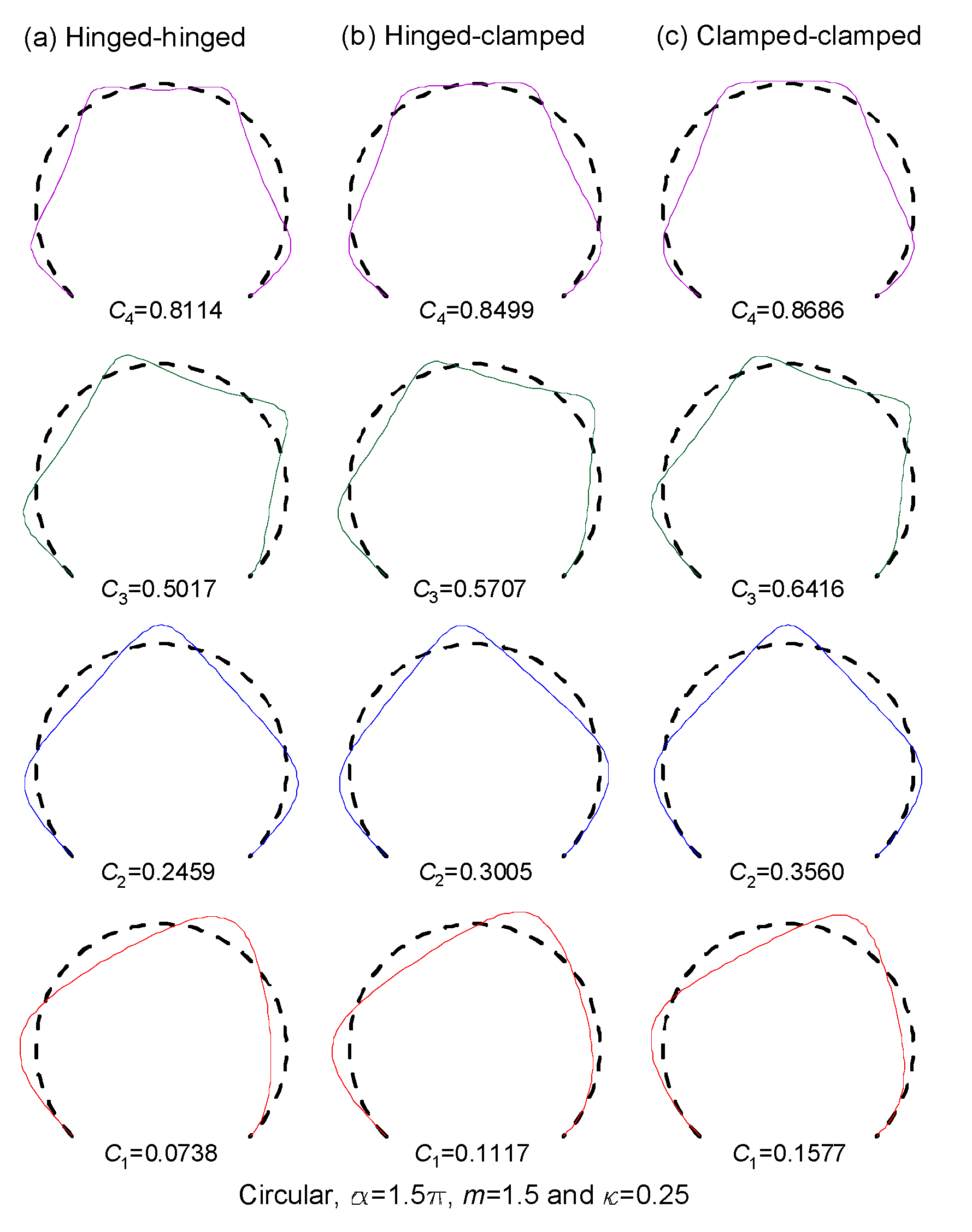
Figure 9 shows an example of mode shapes of the hinged-hinged, hinged-clamped and clamped-clamped arch. The input arch parameters are circular cross-section, , and . In the numerical analysis of differential equations, the radial and tangential deformations are calculated separately. Since these two deformation vectors are perpendicular to each other as shown in Figure 2, the two deformations are represented as one synthesized mode shape. In the values shown in this figure, the end constraint has a great influence on computations. There is no significant difference between the three mode shapes except for the presence or absence of angular rotation at both ends and and of the arch (see boundary conditions, Equations (29)–(34)). That is, there are no significant differences of the nodal points and the maximum amplitude positions between the three mode shapes. The position of the maximum deformation shown in Figure 9 is important for structural safety, and when exposed to dynamic loads over a long period of time, there is a high possibility of fatigue fracture due to resonance, so a periodic soundness check is required at the maximum amplitude positions of the horseshoe arch.
5. Concluding Remarks
This study deals with free vibration analyses of the tapered horseshoe circular arch with constant volume. By applying the equilibrium equations of the arch element acting on the stress resultants and inertia forces, this study finds the differential equations governing free vibrations of such an arch. In the governing equations, the effects of the cross-sectional shape, taper ratio, and volume ratio are simultaneously included. These differential equations were numerically solved using the direct integration method such as the Runge–Kutta method and the determinant search method enhanced by the Regula–Falsi method, and the natural frequencies with the mode shapes were calculated. Convergence analysis was performed for effective integration in the Runge–Kutta scheme. For validation purposes, the natural frequencies of this study and the finite element ADINA were compared, which agreed well with each other. With the comprehensive numerical examples, the parametric studies affecting the natural frequencies and mode shapes were conducted and discussed extensively: the rotatory inertia couple lowers the frequency parameter and has a greater effect on the low mode and large volume ratio; the frequency parameter of the square cross-section is greater than the frequency parameter of the circular cross-section; the frequency parameter decreases with increasing opening angle, while the frequency parameter increases with increasing taper and volume ratios.
Author Contributions
B.K.L. proposed the idea, derived the governing equations and drafted the manuscript, S.J.O. coded programs and obtained the calculations, and T.E.L. and G.S.K. reviewed the literature and discussed the parametric study. All authors have read and agreed to the published version of the manuscript.
Funding
This study was funded by the Wonkwang University Research Fund in 2020.
Conflicts of Interest
The authors declare no conflict of interest.
References
- Lee, B.K.; Oh, S.J.; Lee, T.E. In-plane free vibrations of horseshoe circular arch. J. Korean Soc. Civ. Eng. 2014, 34, 1043–1052. [Google Scholar] [CrossRef]
- Lee, B.K.; Park, K.K.; Oh, S.J.; Lee, T.E. Planar free vibrations of horseshoe elliptic arch. KSCE J. Civil. Eng. 2016, 20, 1411–1418. [Google Scholar] [CrossRef]
- Lee, J.K.; Lee, B.K. Free vibration and buckling of tapered columns made of axially functionally graded materials. Appl. Math. Model. 2019, 75, 73–87. [Google Scholar] [CrossRef]
- Rao, S.S. Vibration of Continuous System; John Wiley & Sons, Inc.: Hoboken, NJ, USA, 2007. [Google Scholar]
- Timoshenko, S.P. Vibration Problem in Engineering; D. Van Nostrand Company, Inc.: New York, NY, USA, 1937. [Google Scholar]
- Henrych, J. The Dynamics of Arches and Frames; Elsevier Science Publishing Company: Amsterdam, The Netherlands, 1981. [Google Scholar]
- Chidamparam, P.; Leissa, A.W. Vibrations and planar curved beams, rings and arches. Appl. Mech. Rev. 1993, 56, 467–483. [Google Scholar] [CrossRef]
- Tufekci, E.; Ozdemir, O. Exact solution of free in-plane vibration of a stepped circular arch. J. Sound Vib. 2016, 295, 725–738. [Google Scholar] [CrossRef]
- Lü, Q.; Lü, C.F. Exact two-dimensional solutions for in-plane natural frequencies of laminated circular arches. J. Sound Vib. 2009, 318, 920–982. [Google Scholar] [CrossRef]
- Joo, S.M.; Park, K.K.; Lee, B.K.; Hwang, H.J. Free vibration analysis of fixed ended parabolic arches. J. Korean Soc. Civ. Eng. 1985, 5, 31–38. [Google Scholar]
- Nieh, K.Y.; Huang, C.S.; Tseng, Y.P. An analytical solution for in-plane free vibration and stability of loaded elliptic arches. Comput. Struct. 2003, 81, 1311–1327. [Google Scholar] [CrossRef]
- Malekzadeh, P.; Setoodeh, A.R.; Barmshouri, E. A hybrid layerwise and differential quadrature method for in-plane free vibration of laminated thick circular arches. J. Sound Vib. 2008, 315, 212–225. [Google Scholar] [CrossRef]
- Shin, Y.J.; Kwon, K.M.; Yun, J.H. Vibration analysis of a circular arch with variable cross-section using differential transformation and generalized differential quadrature. J. Sound Vib. 2008, 309, 9–19. [Google Scholar] [CrossRef]
- Noori, A.R.; Aslan, T.A.; Temel, B. An efficient approach for in-plane free and forced vibrations of axially functionally graded parabolic arches with nonuniform cross section. Compos. Struct. 2018, 200, 701–710. [Google Scholar] [CrossRef]
- Lee, J.K.; Lee, B.K. Free vibration of AFG circular arch with symmetric and anti-symmetric boundary conditions at mid-arc. Symmetry 2020, 12, 417. [Google Scholar] [CrossRef] [Green Version]
- Wilson, J.F.; Lee, B.K. In-plane free vibrations of catenary arches with unsymmetric axes. Struct. Eng. Mech. 1995, 3, 511–525. [Google Scholar] [CrossRef]
- Perkins, N.C. Planar vibration of an elastica arch: Theory and Practice. J. Vib. Acoust. 1990, 112, 374–379. [Google Scholar] [CrossRef]
- Riedel, C.H.; Kang, B.S. Free vibration of elastically coupled dual-span curved beams. J. Sound Vib. 2016, 290, 820–838. [Google Scholar] [CrossRef]
- Oh, S.J.; Lee, B.K.; Lee, I.W. Natural frequencies of non-circular arches with rotatory inertia and shear deformation. J. Sound Vib. 1999, 219, 23–33. [Google Scholar] [CrossRef]
- Lee, B.K.; Lee, T.E.; Choi, J.M. Dynamic optimal arches with constant volume. Int. J. Struct. Stab. Dyn. 2012, 12, 1250044. [Google Scholar] [CrossRef]
- Oh, S.J.; Lee, B.K.; Lee, I.W. Free vibrations of non-circular arches with non-uniform cross-section. Int. J. Solids Struct. 2000, 37, 4871–4891. [Google Scholar] [CrossRef]
- Borg, S.F.; Gennaro, J.J. Advanced Structural Analysis; Van Nostrand Reinhold Company: New York, NY, USA, 1959. [Google Scholar]
- Weaver, W.; Timoshenko, S.P.; Young, D.H. Vibration Problems in Engineering; John Wiley & Sons, Inc.: Hoboken, NJ, USA, 1990. [Google Scholar]
- Burden, R.L.; Faires, D.J.; Burden, A.M. Numerical Analysis; Cengage Learning: Boston, MA, USA, 2016. [Google Scholar]
- Lee, J.K.; Lee, B.K. In-plane free vibration of uniform circular arches made of axially functionally graded materials. Int. J. Struct. Stab. Dyn. 2019, 19, 1950084. [Google Scholar] [CrossRef]
Figure 1.
An example of a horseshoe circular arch as an entrance portal to a hospital at Wonkwang University in Iksan-si, Jeollabuk-do, Korea (Photo by B. K. Lee).
Figure 1.
An example of a horseshoe circular arch as an entrance portal to a hospital at Wonkwang University in Iksan-si, Jeollabuk-do, Korea (Photo by B. K. Lee).

Figure 2.
Geometry of tapered horseshoe circular arch.

Figure 3.
(a) Cross-sectional shape of arch and (b) variation function of depth

Figure 4.
Free body diagram of small arch element.

Figure 5.
Convergence analysis.

Figure 6.
versus curves.

Figure 7.
versus curves.

Figure 8.
versus curves.

Figure 9.
Example of mode shapes.


Table 1.
Comparison of angular frequency between ADINA and this study.
| End Condition | Geometry of Arch with Non-Dimensional Parameters | Angular Frequency (rad/s) | ||
|---|---|---|---|---|
| ADINA | This Study | |||
| Hinged-hinged | 443.2 | 441.0 | ||
| 1428.0 | 1434.5 | |||
| 2932.3 | 2968.5 | |||
| 4147.6 | 4259.5 | |||
| Hinged-clamped | Uniform cross-section | 595.0 | 591.0 | |
| 1574.3 | 1584.6 | |||
| 3040.8 | 3045.5 | |||
| 4323.9 | 4363.9 | |||
| Clamped-clamped | 375.8 | 382.4 | ||
| 841.1 | 852.0 | |||
| 1513.8 | 1534.7 | |||
| 2313.0 | 2375.0 | |||
Table 2.
Effect of rotatory inertia couple on frequency parameter .
| End Condition | Index * | Frequency Parameter | ||||
|---|---|---|---|---|---|---|
| Hinged-hinged | 0.03 | 0 | 0.02628 | 0.08804 | 0.18147 | 0.30340 |
| 1 | 0.02628 | 0.08799 | 0.18124 | 0.30272 | ||
| 0.1 | 0 | 0.04794 | 0.16045 | 0.33027 | 0.54985 | |
| 1 | 0.04791 | 0.16014 | 0.32886 | 0.54594 | ||
| Hinged-clamped | 0.1 | 0 | 0.07270 | 0.19714 | 0.37902 | 0.60448 |
| 1 | 0.07265 | 0.19674 | 0.37736 | 0.60025 | ||
| 0.3 | 0 | 0.12521 | 0.33693 | 0.64030 | 0.90027 | |
| 1 | 0.12497 | 0.33502 | 0.63295 | 0.89397 | ||
| Clamped-clamped | 0.3 | 0 | 0.17660 | 0.39766 | 0.71535 | 0.90445 |
| 1 | 0.17626 | 0.39542 | 0.70764 | 0.89934 | ||
| 0.9 | 0 | 0.29736 | 0.62380 | 1.00197 | 1.03688 | |
| 1 | 0.29611 | 0.61738 | 0.99030 | 1.02230 | ||
* index = 0: without rotatory inertia couple; index = 1: with.
Table 3.
Effect of cross-sectional shape on frequency parameter
| End Condition | Cross-Section | Frequency Paramete | |||
|---|---|---|---|---|---|
| Hinged-hinged | Square | 0.07555 | 0.25147 | 0.51290 | 0.82607 |
| Circular | 0.07384 | 0.24586 | 0.50174 | 0.81136 | |
| Hinged-clamped | Square | 0.11427 | 0.30716 | 0.58290 | 0.86026 |
| Circular | 0.11171 | 0.30045 | 0.57070 | 0.84994 | |
| Clamped-clamped | Square | 0.16130 | 0.36368 | 0.65471 | 0.87560 |
| Circular | 0.15771 | 0.35597 | 0.64163 | 0.86855 | |
* See text for the input arch parameters.
© 2020 by the authors. Licensee MDPI, Basel, Switzerland. This article is an open access article distributed under the terms and conditions of the Creative Commons Attribution (CC BY) license (http://creativecommons.org/licenses/by/4.0/).
Share and Cite
MDPI and ACS Style
Lee, B.K.; Kim, G.S.; Oh, S.J.; Lee, T.E. Free Vibrations of Tapered Horseshoe Circular Arch with Constant Volume. Appl. Sci. 2020, 10, 5431. https://doi.org/10.3390/app10165431
AMA Style
Lee BK, Kim GS, Oh SJ, Lee TE. Free Vibrations of Tapered Horseshoe Circular Arch with Constant Volume. Applied Sciences. 2020; 10(16):5431. https://doi.org/10.3390/app10165431
Chicago/Turabian StyleLee, Byoung Koo, Gweon Sik Kim, Sang Jin Oh, and Tae Eun Lee. 2020. "Free Vibrations of Tapered Horseshoe Circular Arch with Constant Volume" Applied Sciences 10, no. 16: 5431. https://doi.org/10.3390/app10165431
Note that from the first issue of 2016, this journal uses article numbers instead of page numbers. See further details here.