Coplanar Stripline-Fed Wideband Yagi Dipole Antenna with Filtering-Radiating Performance

1
School of Physics and Electronic Electrical Engineering, Huaiyin Normal University, Huaian 223300, China
2
Ministerial Key Laboratory of JGMT, Nanjing University of Science and Technology, Nanjing 210094, China
*
Author to whom correspondence should be addressed.
Electronics 2020, 9(8), 1258; https://doi.org/10.3390/electronics9081258
Submission received: 6 July 2020
/
Revised: 4 August 2020
/
Accepted: 4 August 2020
/
Published: 6 August 2020
(This article belongs to the Special Issue Antennas and Propagation Aspects for Emerging Wireless Communication Technologies)
Abstract
:In this article, a wideband filtering-radiating Yagi dipole antenna with the coplanar stripline (CPS) excitation form is investigated, designed, and fabricated. By introducing an open-circuited half-wavelength resonator between the CPS structure and dipole, the gain selectivity has been improved and the operating bandwidth is simultaneously enhanced. Then, the intrinsic filtering-radiating performance of Yagi antenna is studied. By implementing a reflector on initial structure, it is observed that two radiation nulls appear at both lower and upper gain passband edges, respectively. Moreover, in order to improve the selectivity in the upper stopband, a pair of U-shaped resonators are employed and coupled to CPS directly. As such, the antenna design is finally completed with expected characteristics. To verify the feasibility of the proposed scheme, a filtering Yagi antenna prototype with a wide bandwidth covering from 3.64 GHz to 4.38 GHz is designed, fabricated, and measured. Both simulated and measured results are found to be in good agreement, thus demonstrating that the presented antenna has the performances of high frequency selectivity and stable in-band gain.
1. Introduction
There is an increasing demand for RF front end to possess much more potential characteristics for application in modern wireless communication systems, such as compact structure, low cost, high efficiency, multiple functions, and so on. It is well known that both antennas and filters are two key components in the RF front end as they play important roles in whole communication systems [1,2,3,4,5,6,7]. If the antenna and filter can be integrated into one module, which possesses not only the radiation characteristics but also the filtering function, the extra matching network between these two components can be removed and the footprint of whole system will be reduced efficiently. In this context, antennas with filtering performance have been attracting more and more attention [8,9,10].
Antennas with unidirectional radiation are much more practical in some modern wireless communication systems [8,9,10,11,12,13,14], such as missiles, aircrafts, and vehicles. To accommodate to this tendency, Yagi antennas have been widely used as a kind of classical structure since its original design and operating principles were first described by Uda and Yagi [15,16]. Quite recently, filtering Yagi antennas have been proposed and investigated [17,18,19]. In [17], a filtering quasi-Yagi antenna was designed by using cascade strategy. Multimode balun bandpass filter was directly integrated into the antenna so as to achieve filtering performance. In [19], the principle from filter to antenna was adopted. Yagi structure here acted as the last-stage resonator of a filter. However, antennas designed by these two kinds of methods are bulky. Actually, the Yagi structure can exhibit the filtering performance itself. As demonstrated in [20], the out-of-band gain suppression of Yagi antenna can be improved by optimizing the length and spacing of directors and reflectors, while narrowing the operating bandwidth compared with the conventional counterpart. Meanwhile, it is well known that the CPS structure is much appreciated by engineering according to its advantages in greatly simplifying the differential-fed network for unidirectional radiation antenna and convenient integration with the active circuits and monolithic microwave integrated circuits [21,22,23,24,25].
The main motivation of this article is to propose a CPS-fed wideband Yagi dipole antenna with filtering-radiating performance. The intrinsic filtering performance of the Yagi structure has been utilized here to produce two radiation nulls emerging at both lower and upper passband edges, respectively. To overcome the narrow operation bandwidth caused by this filtering scheme, an open-circuited half-wavelength resonator is introduced between CPS and driven dipole. As such, both the gain selectivity and the operating bandwidth have been enhanced simultaneously. It is demonstrated that the introduced resonator herein serves as a first-order resonator. Moreover, in order to improve the selectivity of the upper passband edge, a pair of U-shaped resonators are employed and coupled to CPS directly. Finally, an antenna prototype with operation frequency band covering from 3.64 GHz to 4.38 GHz is fabricated and measured. All results are observed as being in good agreement, thereby verifying the validity of this design.
2. Design of the Proposed Antenna
Figure 1 illustrates the configuration of the proposed filtering Yagi dipole antenna, which is fabricated on a polytetrafluoroethylene (PTFE) substrate with a relative permittivity of 2.2, thickness of 1 mm, and dimensions of 30 × 42 mm2. The filtering antenna is composed of four parts: CPS for differential signal excitation, a pair of U-shaped resonators symmetrically coupled to the CPS, two-element radiators consisting of a driven element and a reflector, as well as a folded open-circuited half-wavelength resonator inserted between the feedline and driver. All the four parts are printed on the top side of the substrate while no metal parts exist on its bottom to ensure the operating environment of dipole structure. The antenna structure is symmetrical with respect to the reference line along the middle axis of CPS along the x-axis.
2.1. Modified Dipole with Bandwidth Improved (Type A)
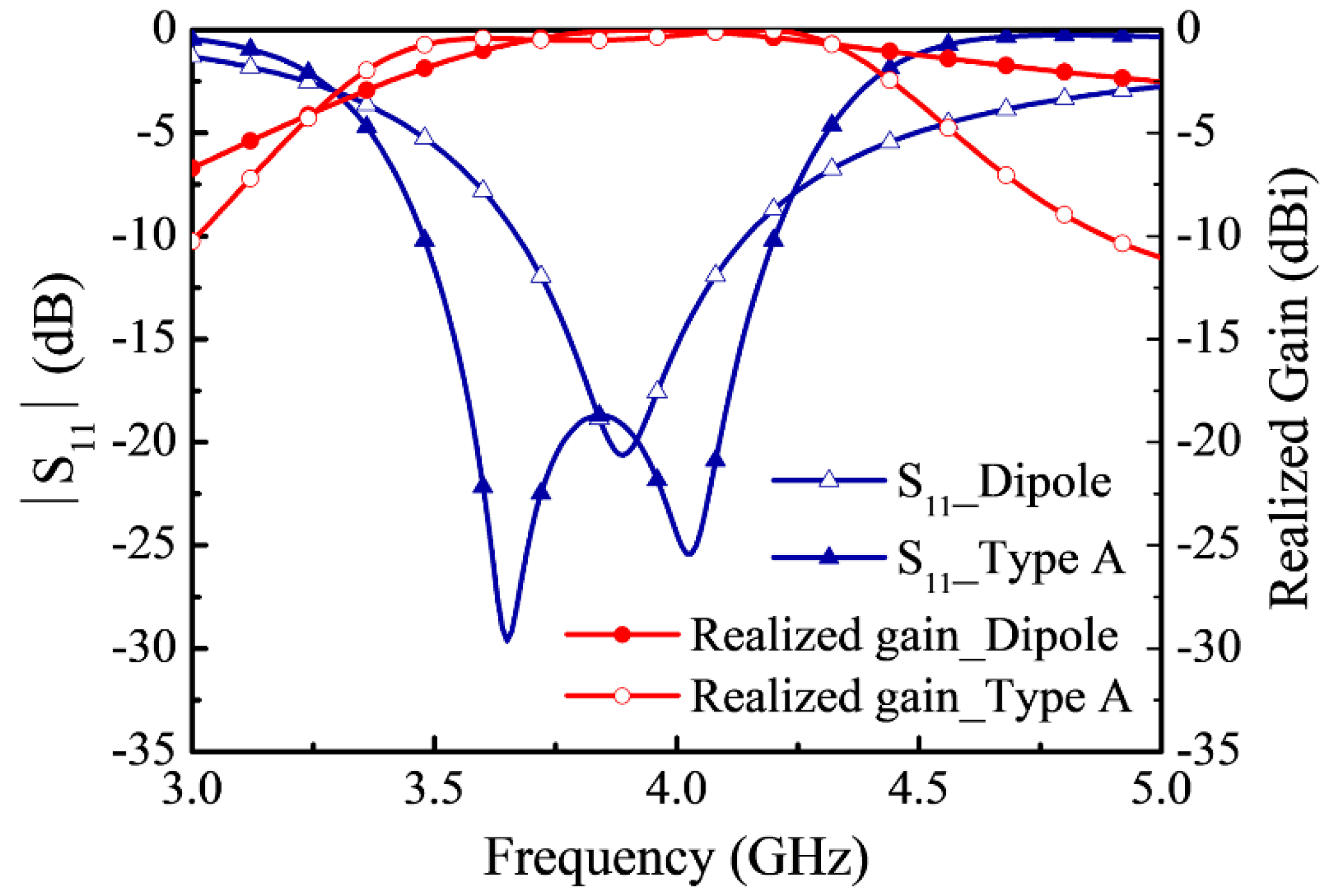
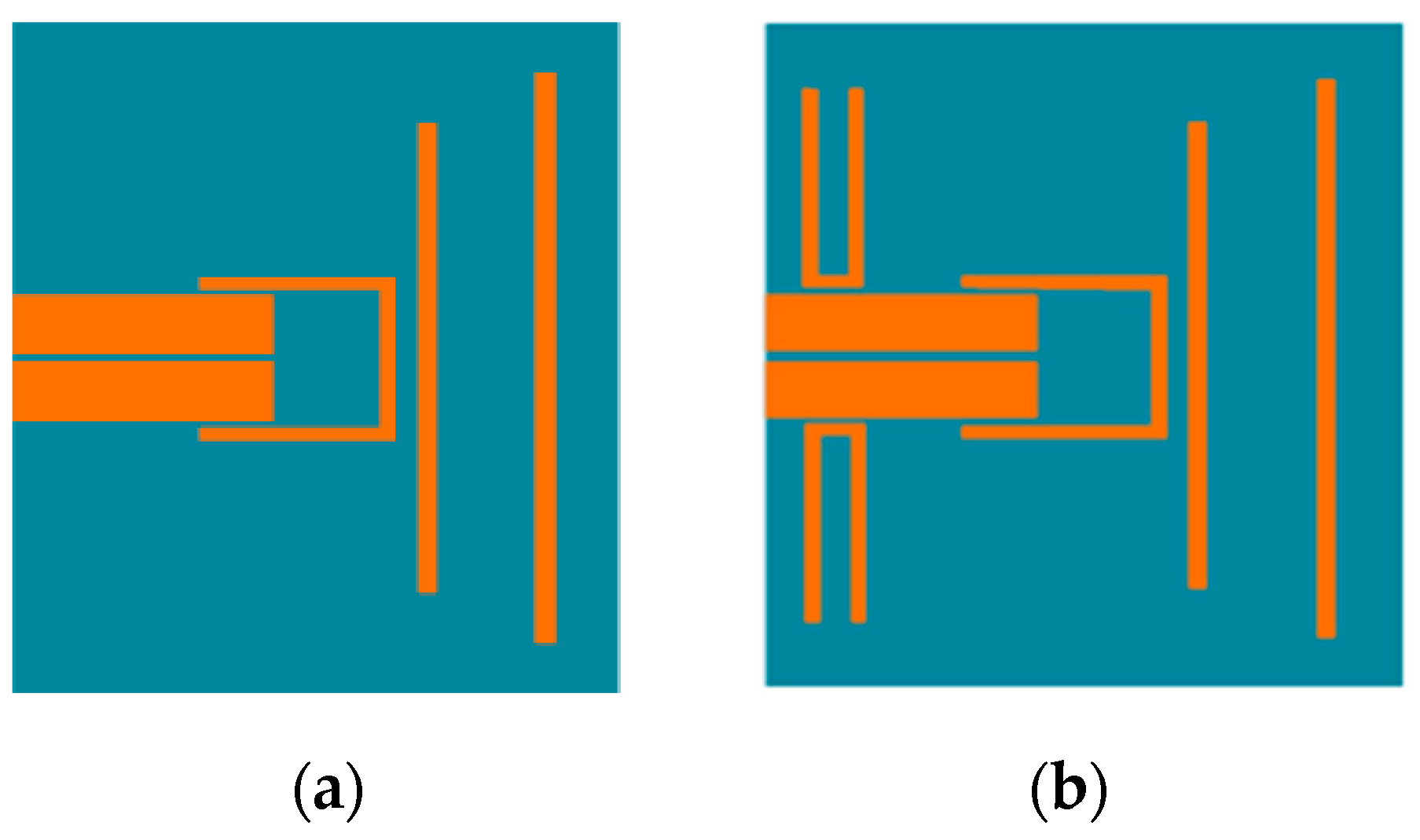
Firstly, the frequency selectivity of dipole antenna is investigated. For clear illustrating, both the conventional dipole antenna and the new dipole structure named type A are presented and depicted in Figure 2a,b, respectively. It should be mentioned that these two dipole antennas are designed on the same substrate and operate at the same frequency. As indicated in Figure 2b, for the new dipole structure, an open-circuited half-wavelength resonator has been introduced as one filtering element between the feedline and dipole. By virtue of this scheme, both the selectivity and bandwidth of dipole antenna are expected to be improved. Comparative results including reflection coefficients and normalized realized gains of antennas are shown in Figure 3. It can be observed that by inserting the half-wavelength resonator, an additional resonance point appears at about 3.65 GHz, naturally resulting in enhanced bandwidth. Besides, for the type A antenna, its in-band gain becomes flatter and the out-of-band suppression is better than the conventional counterpart, which means an improved selectivity.
2.2. Study of the Filtering Performance of Yagi Antenna
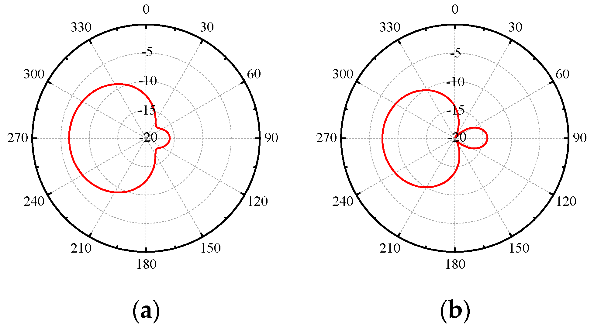
Herein, the filtering performance of Yagi structure itself is discussed. A typical three-element Yagi structure, including both reflector and director, is utilized and shown in Figure 4. By optimizing the parameters, a filtering-radiating Yagi antenna can be obtained. Table 1 tabulates the detailed dimensions of traditional and optimized Yagi antenna. A comparison about normalized realized gain and reflection coefficient curves versus frequency between them is provided in Figure 5. It can be easily observed that after the optimization process, the roll-off performance for both the realized gain and |S11| curves have been improved remarkably, revealing the desired filtering performance. In fact, the filtering property, especially out-of-band gain suppression is here caused by the enhanced loaded Q-factor, which is influenced by the distance between the driver and parasitic elements and will be higher under small element spaces [10]. The described optimization exactly reduces the distances among elements, thus increasing the loaded Q-factor. Besides, it is seen that not only the gain of the optimized one becomes flatter, but also the upper and lower radiation nulls are generated. One thing should be mentioned that radiation nulls are produced by the intrinsic characteristic of the Yagi antenna. It is known that the parasitic element working as director or reflector is determined by the phase condition between the currents on the driver and the element. If the phase of current on parasitic element is prior to that of the driver, the parasitic one will act as a director. Similarly, if the phase of the current on the parasitic element is delayed to that of driver, a reflector can be achieved. Besides, there is no doubt that phase condition is related to the operating frequency. As such, the radiation pattern and beam direction will turn 180 degrees at some certain frequencies where the reflector or director change their role. In this context, when the front-to-back ratio reaches its minimum, radiation nulls appear. The radiation nulls at the upper and lower band edges are caused by the director and reflector, respectively. It should also be noted that the resonant frequency will also be changed slightly with different distance values as the distances will affect the coupling condition for the Yagi dipole antenna [26,27,28,29,30,31,32]. To verify the aforementioned statement, the radiation patterns at these two radiation nulls are displayed in Figure 6. It can be clearly found that beam direction has been reversed. The optimization process changes the distances among elements, which determines coupling and phase condition. Therefore, the location of radiation nulls can be controlled.
In addition, as indicated in Table 1, the most difference between traditional and optimized antennas lies in the length of parasitic element and distance from it to the driven one. In this context, the relationship between the occurring frequency of lower radiation null and the spacing from reflector to driven element D2, as well as the length of reflector Ly3 are selected for investigation and shown in Figure 7. It can be found that when D2 remains unchanged, increasing Ly3 will move down the frequency location of radiation null. Moreover, with a fixed Ly3, increasing D2 can also result in a variation of the frequency of radiation null. Herein, according to the above discussions, both the length of the parasitic element and the distance from the driven element to parasitic one in Yagi structure has been properly selected to obtain good gain selectivity for better filtering performance.
2.3. Realization of the Proposed Filtering Yagi Dipole Antenna
Based on the aforementioned dipole antenna with improved selectivity and enhanced bandwidth, a Yagi dipole antenna named type B is presented by adding a reflector in the dipole structure (Type A), as shown in Figure 8a. As we have proved that the reflector can reflect electromagnetic waves and enhance the directivity of antenna. Also, it actually can improve the out of band suppression. Figure 9 sketches the realized gain of proposed Type B. From the gain results, it is found that two radiation nulls appear at the lower and upper passband edges; nevertheless, the suppression of the upper stopband is not very good. This phenomenon is caused by the fact that the introduced folded resonator hardly influences the radiation of driver and cannot work as a director due to its limited length. This is exactly the reason why the filtering performance of Type B at the upper band edge is worse than the optimized Yagi antenna. Limited by the CPS feedline, the director has not been utilized in this proposed structure. Moreover, inside the operation band, there also exist two resonance points, so as to maintain a wide bandwidth. Compared with type A antenna, the filtering characteristic of type B is enhanced. Undoubtedly, the increment on filtering performance is achieved by intrinsic property of Yagi antenna.
To further improve the suppression in the upper stopband, a pair of U-shaped resonators are deployed and directly coupled to the CPS feedline. Until now, the implementation of wideband Yagi dipole filtering antenna—i.e., antenna type C—is finally accomplished, as shown in Figure 8b. Figure 9 depicts its realized gain. It is found that one additional radiation null has been achieved at the near edge of operating frequency band, thus manifesting an improved gain selectivity than the one caused by the reflector. Herein, the introduced U-shaped folded line functions as an open-circuited half-wavelength resonator corresponding to a specific frequency; thus, signals at this frequency cannot pass through the feedline but couple to the U-shaped resonator. One thing should be mentioned that the U-shaped folded line is not same as those reported structures with notch since ground is nonexistent. The introduced U-shaped line radiates here and works just like a folded dipole antenna, which possesses an omnidirectional radiation pattern. As such, the omnidirectional radiation caused by U-shaped line worsens the front-to-back ratio, leading to an additional radiation null.
3. Fabrication and Experimental Results
Figure 10 shows the photograph of fabricated antenna prototype. The dimensions of the antenna prototype are: W1 = 3.8 mm, W2 = 1 mm, W3 = 0.8 mm, Wdri = 1 mm, Wref = 1 mm, L1 = 13 mm, L2 = 28.4 mm, L3 = 27.4 mm, L4 = 13 mm, Ldri = 30 mm, Lref = 36 mm, g1 = 0.2 mm, g2 = 0.3 mm, g3 = 5 mm, g4 = 1 mm, g5 = 5 mm, and g6 = 0.3 mm. The CPS feedline is achieved by a pair of parallel coupled lines which are respectively connected with the inner and outer conductor of SMA, thus forming a balun structure. Besides, the flange of SMA is selected with a compact size for reducing its influence on radiation. The proposed antenna is easily fabricated and assembled.
Measured and simulated reflection coefficients and gains of the fabricated antenna prototype are provided in Figure 11. It can be found that the measured operating frequency band covering from 3.64 GHz to 4.38 GHz (18.5%) is little higher than the simulated one. Moreover, these two gain curves have the same tendency with the variation of frequency. The emerged radiation nulls at specific frequency locations agree well with our expectations. Compared with simulated result, the measured one also slightly moves toward a higher frequency, which corresponds to the results of reflection coefficients. Figure 12 depicts the measured and simulated radiation patterns of fabricated antenna prototypes operating at 3.66 GHz and 4.13 GHz, which means the resonant frequencies inside the working band. Measured patterns match well with the simulated ones, except the measured cross-polarization is a little higher than the simulated one.
To highlight the advantages of this work, the performances in comparison with other reported counterparts are summarized in Table 2. It can be concluded from this table that our presented work exhibits good properties of compact size, wider bandwidth, simple structure of one-layer circuit, as well as an improved gain selectivity.
4. Conclusions
In this article, a wideband filtering-radiating Yagi dipole antenna is presented and investigated. With resorting to the CPS differential feed network, the design complexity has been effectively reduced. Then, by introducing an open-circuited half-wavelength resonator between CPS and dipole, a new dipole antenna with improved selectivity and extended bandwidth is proposed. Afterwards, the intrinsic filtering performance of Yagi structure has been studied and implemented on the dipole antenna. Meanwhile, a pair of U-shaped resonators are employed and coupled to CPS directly so as to accomplish the filtering radiation purpose. An antenna prototype has been fabricated and tested. Measured results demonstrate a wide bandwidth covering from 3.64 GHz to 4.38 GHz (18.5%) and three desired radiation nulls. Since no filtering and matching networks are involved, the structure of the proposed antenna is very simple. In addition, this antenna has the features of low profile, compact size, and easy fabrication, which will make it a good candidate for modern 5G wireless communication systems.
Author Contributions
Methodology, investigation, writing—original draft, and data curation, Y.C.; Conceptualization and project administration, G.L.; Resources, S.W.; Supervision, writing—review and editing, J.W. All authors have read and agreed to the published version of the manuscript.
Funding
This work was supported by the National Natural Science Foundation of China (grant no. 61771247).
Acknowledgments
The authors wish to express their thanks for the support provided by the National Natural Science Foundation of China (grant no. 61771247).
Conflicts of Interest
The authors declare no conflict of interest.
References
- Pozar, D.M. Microwave Engineering, 2nd ed.; Wiley: New York, NY, USA, 1998. [Google Scholar]
- Yang, N.; Caloz, C.; Wu, K. Co-designed CPS UWB filter-antenna system. In Proceedings of the 2007 IEEE Antennas and Propagation Society International Symposium, Honolulu, HI, USA, 9–15 June 2007; Volume 6, pp. 1433–1436. [Google Scholar]
- Shen, P.; Qi, Y.; Wang, X.; Zhang, W.; Yu, W. A 2 × 2 MIMO Throughput Analytical Model for RF Front End Optimization. J. Commun. Inf. Netw. 2020, 5, 194–203. [Google Scholar]
- Wu, W.; Ker, M.; Chen, S.; Chen, J.; Linten, D.; Groeseneken, G. RF/High-Speed I/O ESD Protection: Co-optimizing Strategy Between BEOL Capacitance and HBM Immunity in Advanced CMOS Process. IEEE Trans. Electron. Devices 2020, 67, 2752–2759. [Google Scholar] [CrossRef]
- Harati, P.; Kallfass, I. Analogue feed-forward carrier recovery for millimetre-wave broadband wireless links. IET Microw. Antennas Propag. 2020, 14, 366–373. [Google Scholar] [CrossRef]
- Tabarani, F.; Boccia, L.; Calzona, D.; Amendola, G.; Schumacher, H. Power-efficient full-duplex K/Ka-band phased array front-end. IET Microw. Antennas Propag. 2020, 14, 268–280. [Google Scholar] [CrossRef]
- Garcia, J.C.B.; Kamoun, M.; Sibille, A. Complexity Adaptive Spatial Processing of ESPAR Antenna Systems. IEEE Trans. Wirel. Commun. 2020, 19, 3700–3711. [Google Scholar] [CrossRef]
- Jian, F.L.; Zhi, N.C.; Duo, L.W.; Gary, Z.; Yan-Jie, W. Dual-beam filtering patch antennas for wireless communication application. IEEE Trans. Antennas Propag. 2018, 66, 3730–3734. [Google Scholar]
- Zhang, G.; Wang, J.; Wu, W. Wideband balun bandpass filter explored for a balanced dipole antenna with high selectivity. Electron. Lett. 2016, 52, 1153–1155. [Google Scholar] [CrossRef]
- Deng, J.; Hou, S.; Zhao, L.; Guo, L. A reconfigurable filtering antenna with integrated bandpass filters for UWB/WLAN applications. IEEE Trans. Antennas Propag. 2018, 66, 401–404. [Google Scholar] [CrossRef]
- Sohail, M.F.; Leow, C.Y.; Won, S. Energy-Efficient Non-Orthogonal Multiple Access for UAV Communication System. IEEE Trans. Veh. Technol. 2019, 68, 10834–10845. [Google Scholar] [CrossRef]
- Kim, J.; Lee, H.; Chong, S. Super-MAC Design for Tightly Coupled Multi-RAT Networks. IEEE Trans. Commun. 2019, 67, 6939–6951. [Google Scholar] [CrossRef]
- Capovilla, C.E.; Casella, I.R.; Costa, F.F.; Luz-de-Almeida, L.A.; Sguarezi Filho, A.J. DFIG-Based Wind Turbine Predictive Control Employing a Median Filter to Mitigate Impulsive Interferences on Transmitted Wireless References. IEEE Trans. Ind. Appl. 2019, 55, 4091–4099. [Google Scholar] [CrossRef]
- Wu, C.; Wang, Y.; Yin, Z. Realizing Railway Cognitive Radio: A Reinforcement Base-Station Multi-Agent Model. IEEE Trans. Intell. Transp. Syst. 2019, 20, 1452–1467. [Google Scholar] [CrossRef]
- Yagi, H. Beam transmission of the ultra short waves. Proc. IRE 1928, 16, 715–741. [Google Scholar] [CrossRef]
- Liu, S.; Raad, R.; Theoharis, P.; Tubbal, F.A. Printed Yagi Antenna for CubeSat with Multi-Frequency Tilt Operation. Electronics 2020, 9, 986. [Google Scholar] [CrossRef]
- Tang, H.; Chen, J.X.; Chu, H.; Zhang, G.Q.; Yang, Y.J.; Bao, Z.H. Integration design of filtering antenna with load-insensitive multilayer balun filter. IEEE Trans. Compon. Packag. Manuf. Technol. 2016, 6, 1408–1416. [Google Scholar] [CrossRef]
- Shi, J.; Wu, X.; Chen, Z.N.; Qing, X.; Lin, L.; Chen, J.; Bao, Z. A compact differential filtering Quasi-Yagi antenna with high frequency selectivity and low cross-polarization levels. IEEE Antennas Wirel. Propag. Lett. 2015, 14, 1573–1576. [Google Scholar] [CrossRef]
- Deng, H.W.; Xu, T.; Liu, F. Broadband pattern reconfigurable filtering microstrip antenna with Quasi-Yagi structure. IEEE Antennas Wirel. Propag. Lett. 2018, 17, 1127–1131. [Google Scholar] [CrossRef]
- Wang, Z.P.; Hall, P.S.; Gardner, P. Yagi antenna with frequency domain filtering performance. In Proceedings of the 2012 IEEE International Symposium on Antennas and Propagation, Chicago, IL, USA, 8–14 July 2012; pp. 1–2. [Google Scholar]
- Liang, Z.; Yuan, J. Compact dual-wideband multi-mode printed quasi-Yagi antenna with dual-driven elements. IET Microw. Antennas Propag. 2020, 14, 662–670. [Google Scholar] [CrossRef]
- Byeon, C.W.; Eun, K.C.; Park, C.S. A 2.65-pJ/Bit 12.5-Gb/s 60-GHz OOK CMOS Transmitter and Receiver for Proximity Communications. IEEE Trans. Microw. Theory Tech. 2020, 68, 2902–2910. [Google Scholar] [CrossRef]
- Yang, L.; Zhuang, J. Compact quasi-Yagi antenna with enhanced bandwidth and stable high gain. Electron. Lett. 2020, 56, 219–220. [Google Scholar] [CrossRef]
- Sarkar, D.; Mikki, S.M.; Antar, Y.M.M. Poynting Localized Energy: Method and Applications to Gain Enhancement in Coupled Antenna Systems. IEEE Trans. Antennas Propag. 2020, 68, 3978–3988. [Google Scholar] [CrossRef]
- Alekseytsev, S.A.; Gorbachev, A.P. The Novel Printed Dual-Band Quasi-Yagi Antenna with End-Fed Dipole-Like Driver. IEEE Trans. Antennas Propag. 2020, 68, 4088–4090. [Google Scholar] [CrossRef]
- Zhou, Z.; Wei, Z.; Tang, Z.; Yin, Y. Design and Analysis of a Wideband Multiple-Microstrip Dipole Antenna with High Isolation. IEEE Antennas Wirel. Propag. Lett. 2019, 18, 722–726. [Google Scholar] [CrossRef]
- He, K.; Gong, S.; Gao, F. A Wideband Dual-Band Magneto-Electric Dipole Antenna with Improved Feeding Structure. IEEE Antennas Wirel. Propag. Lett. 2014, 13, 1729–1732. [Google Scholar] [CrossRef]
- Liu, Y.; Yi, H.; Wang, F.; Gong, S. A Novel Miniaturized Broadband Dual-Polarized Dipole Antenna for Base Station. IEEE Antennas Wirel. Propag. Lett. 2013, 12, 1335–1338. [Google Scholar] [CrossRef]
- Wang, Z.; Wu, J.; Yin, Y.; Liu, X. A Broadband Dual-Element Folded Dipole Antenna with a Reflector. IEEE Antennas Wirel. Propag. Lett. 2014, 13, 750–753. [Google Scholar] [CrossRef]
- Lehmensiek, R.; de Villiers, D.I.L. Constant Radiation Characteristics for Log-Periodic Dipole Array Antennas. IEEE Trans. Antennas Propag. 2014, 62, 2866–2869. [Google Scholar]
- Tao, J.; Feng, Q.; Liu, T. Dual-Wideband Magnetoelectric Dipole Antenna with Director Loaded. IEEE Antennas Wirel. Propag. Lett. 2018, 17, 1885–1889. [Google Scholar] [CrossRef]
- Yin, H.; Wang, M.; Wang, J.; Wu, W. A compact wideband filtering quasi-yagi antenna. In Proceedings of the 2017 Sixth Asia-Pacific Conference on Antennas and Propagation (APCAP), Xi’an, China, 16–19 October 2017; pp. 1–3. [Google Scholar]
Figure 1.
Geometry of the proposed filtering Yagi dipole antenna in 3D view.

Figure 2.
Dipole antennas. (a) Conventional. (b) Proposed type A.

Figure 3.
Comparison about reflection coefficients and realized gains between the conventional dipole antenna and proposed Type A.
Figure 3.
Comparison about reflection coefficients and realized gains between the conventional dipole antenna and proposed Type A.

Figure 4.
Configuration of a three-element Yagi antenna.

Figure 5.
Comparison about normalized realized gain and reflection coefficient curves versus frequency between the traditional and optimized Yagi antenna.
Figure 5.
Comparison about normalized realized gain and reflection coefficient curves versus frequency between the traditional and optimized Yagi antenna.

Figure 6.
E planes of the optimized Yagi operating at two radiation nulls. (a) 3.32 GHz. (b) 4.66 GHz.
Figure 6.
E planes of the optimized Yagi operating at two radiation nulls. (a) 3.32 GHz. (b) 4.66 GHz.

Figure 7.
Relationship between the occurring frequency of lower radiation null and the spacing from reflector to driven element D2, as well as the length of reflector Ly3.
Figure 7.
Relationship between the occurring frequency of lower radiation null and the spacing from reflector to driven element D2, as well as the length of reflector Ly3.

Figure 8.
Configuration of proposed Yagi dipole antennas. (a) Type B. (b) Type C.

Figure 9.
Comparison about reflection coefficients and normalized realized gains between the conventional dipole antenna and proposed Type A.
Figure 9.
Comparison about reflection coefficients and normalized realized gains between the conventional dipole antenna and proposed Type A.

Figure 10.
Photograph of the fabricated antenna prototype.

Figure 11.
Measured and simulated reflection coefficients and realized gains of the fabricated antenna prototype.
Figure 11.
Measured and simulated reflection coefficients and realized gains of the fabricated antenna prototype.

Figure 12.
Measured and simulated radiation patterns of fabricated antenna prototype operating at (a) 3.66 GHz. (b) 4.13 GHz.
Figure 12.
Measured and simulated radiation patterns of fabricated antenna prototype operating at (a) 3.66 GHz. (b) 4.13 GHz.


Table 1.
Dimensions of Yagi antenna in Figure 4
Table 1.
Dimensions of Yagi antenna in Figure 4
| Type | Parameters | W | Ly1 | Ly2 | Ly3 | D1 | D2 |
|---|---|---|---|---|---|---|---|
| Traditional | Values(mm) | 2 | 30 | 31.22 | 26.33 | 18.98 | 15.3 |
| Optimized | Values(mm) | 2 | 30 | 27.55 | 33.67 | 2.02 | 3.06 |
Table 2.
Comparison among filtering Yagi antennas
| Ref. | Bandwidth (%) | Central Frequency | Design Principle | Realized Gain (dBi) | Size (λ0) | Number of Radiation Null | Number of Layer |
|---|---|---|---|---|---|---|---|
| [17] | 16.7 | 1.72 GHz | Cascade | 5.9 | 0.6 × 0.6 × 0.007 | 0 | 3 |
| [18] | 5.5 | 1.82 GHz | Cascade | 5.1 | 0.75 × 0.6 × 0.007 | 0 | 3 |
| [19] | 25 | 5.2 GHz | From filter to antenna | 7.0 | 0.65 × 0.62 × 0.009 | 1 | 1 |
| [20] | 8.7 | 0.95 GHz | From antenna to filter | 10.6 | 0.55 × 0.15 × N.A | 2 | 1 |
| Our work | 18.5 | 4.01 GHz | From antenna to filter | 5.8 | 0.56 × 0.4 × 0.013 | 3 | 1 |
© 2020 by the authors. Licensee MDPI, Basel, Switzerland. This article is an open access article distributed under the terms and conditions of the Creative Commons Attribution (CC BY) license (http://creativecommons.org/licenses/by/4.0/).
Share and Cite
MDPI and ACS Style
Chen, Y.; Lu, G.; Wang, S.; Wang, J. Coplanar Stripline-Fed Wideband Yagi Dipole Antenna with Filtering-Radiating Performance. Electronics 2020, 9, 1258. https://doi.org/10.3390/electronics9081258
AMA Style
Chen Y, Lu G, Wang S, Wang J. Coplanar Stripline-Fed Wideband Yagi Dipole Antenna with Filtering-Radiating Performance. Electronics. 2020; 9(8):1258. https://doi.org/10.3390/electronics9081258
Chicago/Turabian StyleChen, Yong, Gege Lu, Shiyan Wang, and Jianpeng Wang. 2020. "Coplanar Stripline-Fed Wideband Yagi Dipole Antenna with Filtering-Radiating Performance" Electronics 9, no. 8: 1258. https://doi.org/10.3390/electronics9081258
Note that from the first issue of 2016, this journal uses article numbers instead of page numbers. See further details here.